Article

Thermal Assessment of Nano-Particulate Graphene-Water/Ethylene Glycol (WEG 60:40) Nano-Suspension in a Compact Heat Exchanger

1
School of Mechanical Engineering, The University of Adelaide, Adelaide, SA 5000, Australia
2
Division of Computational Physics, Institute for Computational Science, Ton Duc Tang University, Ho Chi Minh City 758307, Vietnam
3
Faculty of Electrical and Electronics Engineering, Ton Duc Thang University, Ho Chi Minh City 758307, Vietnam
4
School of Engineering, Ocean University of China, Qingdao 266100, China
5
Department of Mechanical Engineering, Lamar University, Beaumont, TX 77705, USA
6
School of Mechanical Engineering, Federal University of Uberlandia (UFU), Av. Joao Naves de Avila, 2121, Santa Monica, Uberlandia, MG 38408-514, Brazil
*
Author to whom correspondence should be addressed.
Energies 2019, 12(10), 1929; https://doi.org/10.3390/en12101929
Submission received: 23 April 2019 / Revised: 9 May 2019 / Accepted: 15 May 2019 / Published: 20 May 2019
(This article belongs to the Special Issue Experimental Heat Transfer in Energy Systems)

Abstract

:
In the present study, we report the results of the experiments conducted on the convective heat transfer of graphene nano-platelets dispersed in water-ethylene glycol. The graphene nano-suspension was employed as a coolant inside a micro-channel and heat-transfer coefficient (HTC) and pressure drop (PD) values of the system were reported at different operating conditions. The results demonstrated that the use of graphene nano-platelets can potentially augment the thermal conductivity of the working fluid by 32.1% (at wt. % = 0.3 at 60 °C). Likewise, GNP nano-suspension promoted the Brownian motion and thermophoresis effect, such that for the tests conducted within the mass fractions of 0.1%–0.3%, the HTC of the system was improved. However, a trade-off was identified between the PD value and the HTC. By assessing the thermal performance evaluation criteria (TPEC) of the system, it was identified that the thermal performance of the system increased by 21% despite a 12.1% augmentation in the PD value. Furthermore, with an increment in the fluid flow and heat-flux applied to the micro-channel, the HTC was augmented, showing the potential of the nano-suspension to be utilized in high heat-flux thermal applications.

1. Introduction

With the advancement in the thermal process engineering, efficient cooling technologies with the capability to dispossess heat from high heat-flux areas are highly demanded, and this is the main driver for developing various types of heat exchangers for different cooling applications [1,2]. Heat exchangers have a vital role in chemical and mechanical processes by providing an opportunity to exchange a large amount of heat between a heat source and a cold fluid within a confined space [3,4]. Depending on the application of the heat exchanger, available space, and the type of the heat transfer fluid, various configurations of the heat exchangers have been designed. In addition, with a continuous progress in thermal engineering, size and geometry of the heat exchangers have been improved, such that the new generation of heat exchangers are small, but offer more thermal efficiency and longer operation times [5]. Recently, compact heat exchangers have been receiving special attention thanks to their area-to-volume ratio and sufficient surface contact between the hot and the cold sections [6].
A compact heat exchanger offers a relatively large heat transfer coefficient (HTC) compared to the conventional ones, and represents a relatively short thermal response, which results in better thermal performance, compared with the conventional heat exchangers [7].
Micro-channel heat exchangers are a new generation of heat exchangers, which offer an anomalous area-to-volume ratio, nominating them as a very suitable medium for heat and mass transfer. Large convective heat and mass transfer coefficient, low fabrication cost, simple design, and low pumping power are some potential advantages offered by micro-channels [8]. Such advantages can be intensified if the thermal and hydraulic performance of the carrying fluid is plausible. The thermo-physical properties of the carrying fluid include thermal conductivity, density, heat capacity, and viscosity, and can dramatically improve the thermal performance of the system. When it comes to the thermal performance of a carrying fluid, the thermal conductivity has an important role in the system [9]. Conventional coolants, despite their applications in various industries, have reached their limitations. For example, water is the most common coolant in the cooling systems, which has a relatively small thermal conductivity (e.g., 0.6–0.65 W/m K) and a low boiling temperature (e.g., 99.98 °C), and therefore cannot be employed in high heat-flux systems. The traditional coolants like ethylene glycol, water, or oils have poor thermal conductivity, and as a result, they limit the thermal performance of the cooling system.
With the introduction of nanofluids in the Aragon National Laboratory (ANL) [9], many studies have been conducted to assess the potential usage of the nanofluid inside the thermal systems, with the view to identify the most plausible type of nanofluid for the commercialization [10,11,12,13,14,15,16,17,18,19]. A nanofluid is a suspension of a conductive powder dispersed in a common cooling fluid such as water or ethylene glycol. The presence of the conductive particles improves the thermo-physical properties of the base fluid, including (but not limited to) thermal conductivity. The improvement in the thermal conductivity of the conventional coolant can promote the convective and conduction heat transfer through the heat exchanger. For instance, in an investigation conducted by Bowers et al. [20], the heat transfer characteristics of two aqueous nanofluids, including silica and alumina, in a micro-channel was studied. They found that the presence of the nanoparticles augmented the friction forces within the base fluid. Likewise, the friction factor was larger than that of the friction factor obtained for the conventional systems, and the existing equations lost out to anticipate the friction factor of the nanofluid. The convective HTC of both nanofluids was greater than that of measured for the carrying fluid, which was ascribed to the increment in the thermal properties of the working fluid, owing to the usage of the nanoparticles. They also noticed that the pressure drop (PD) augmentation of the system could augment the pumping power required for the system. By conducting some experiments, Manay et al. [21] studied the potential impact of the micro-channel height and the volumetric concentration of titanium oxide nanoparticles on the thermal performance and fluid-flow specifications of the nanofluid. They found that the convection heat transfer mechanism was promoted, while a small increase in the PD value was registered, which slightly augmented the pumping power. In addition, the HTC of the system increased with an addition in the nanoparticles concentration. Radwan et al. [22] developed a new method involving the use of a solar micro-channel heat sink working with alumina and SiC nanofluids. The thermal performance of the heat sink was evaluated at various volume fractions of the nanoparticles and it was identified that an aqueous silica carbide nanofluid can potentially achieve better thermal performance compared to an alumina one. In addition, adding more nanoparticles to the working fluid further improved the thermal performance of the heat sink by diminishing the cell temperature. It was also identified that the use of the nanoparticles augmented the friction factor parameter as well, which could potentially affect the net electrical power for pumping the nanofluids.
To evaluate the potential influence of the chemical synthesis on the physical properties, and also the thermal performance of the systems, Sarafraz et al. [17] performed several experiments to evaluate the pumping power, thermal performance, and the fluid behavior of a biologically-produced nanofluid inside a micro-channel heat exchanging block. They assessed the system in laminar heat and fluid-flow and noticed that the presence of the synthesized silver nanoparticles can improve the performance of the system, while adding small increments to the PD value. By assessing the performance evaluation index of the system, they showed that despite the increase in the PD of the system, the enhancement of the HTC could compensate the penalty for the PD. It was also found that the total thermal performance can be improved by 37% at Re = 1400 and at a mass fraction of 0.05%. In another study, Zhang et al. [23] evaluated the heat transfer characteristics of GO/H2O nanofluid in a two-phase region in a micro-channel and noticed that the thermal performance of the micro-channel was deteriorated due to the deposition of the graphene oxides inside the micro-channel. In addition, it was identified that graphene oxide created a porous film within the micro-channel, resulting in the blockage of some channels, which further reduced the performance of the system.
Xia et al. [24] carried out an experimental assessment to understand the thermal behavior of alumina and titana nanofluid inside a heat sink at various volumetric concentrations of the nanoparticles. The measured data showed that by adding more nanomaterials to the carrying fluid, the thermal conductivity and viscosity of the nanofluid increased. The former could improve the thermal performance of the system, while the latter could affect the friction forces and the PD value of the system. In another similar investigation performed by Anbumeenakshi et al. [25], the potential influence of nanofluid and the irregular heating of the micro-channel on the thermal performance of the system was experimented and discussed. The micro-channel utilized for the study had 30 rectangular channels with a mean hydraulic diameter of 0.727 mm. To generate a non-uniform heat-flux to the system, a switchboard was used to employ two out of three heaters at the same time. It was found that alumina nanofluid can potentially provide better thermal performance and the micro-channel showed the lowest surface temperature for the case of alumina at vol.% = 0.25. The results of the experiments showed that despite a non-uniform heating condition, nanofluids offer a distinguished potential for cooling the system. To quantify the convective heat transfer of carbon nanotube nanofluid, Sarafraz et al. [26] accomplished a series of experiments with a rectangular micro-channel and assessed the HTC of the system together with the PD for nanofluids at wt. % = 0.05 to 0.1. They assessed the potential effect of various operating parameters, including (but not limited to) heat-flux perpendicular to micro-channel, the flow rate of the flow, and the concentration of the nanofluid on the average HTC of the system. They found that the temperature distribution within the micro-channel was suppressed when nanofluid was used inside the micro-channel. In addition, due to the deposition of the nanotubes, the fouling thermal resistance parameter increased, showing an asymptotic behavior with time. Hence, the thermal performance was decreased due to the thermal resistance induced to the system due to the fouling of carbon nanotubes.
Abdollahi et al. [27] completed a series of experiments to investigate the heat transfer specifications of various nanofluids inside a micro-channel, with a V-shaped inlet and outlet arrangement. They found that silica nanofluid could potentially have the highest heat transfer rate compared to alumina, copper oxide, and ZnO nanofluids. In addition, it was found that with a decrease in the size of the nanoparticles, the thermal performance of the system was improved and the PD value was insignificant in comparison with water (as the working fluid). The study indicated that nanofluids could promote the heat transfer within a V-shape micro-channel heat-exchanging block. Since there is extensive research on the nanofluids’ thermal performance in a micro-channel, Table 1, in which a summary of nanofluid-related studies in micro-channels are presented, is displayed below.
According to the aforementioned literature, it can be stated that the thermal performance of the micro-channel is extremely dependent on the thermo–physical properties of the nanofluids. Despite extensive research conducted on nanofluids, there are controversial results reported in the literature, some supporting the potential application of the nanofluids, and others refusing the nanofluids due to the augmentation in friction forces and scale formation inside the compact heat exchanger. Hence, in this study, an experimental study was conducted to assess the thermal performance and fluid flow of graphene nano-platelets-water/ethylene glycol 60:40 (hereafter WEG) inside a micro-channel heat exchanger. A test rig was fabricated to identify the effect of various operating conditions like heat-flux, flow rate, inlet temperature, and the mass fraction of the nanofluid on the HTC and PD of the system. In addition, the thermal conductivity of the nanofluid was experimentally measured to ensure the plausible influence of the graphene nano-platelets on the heat transfer characteristics of WEG.

2. Experimental

2.1. Test Rig

Figure 1 shows the image of the experimental apparatus used in this investigation. The system includes an insulated tank to keep the nanofluid, a circulation loop including the pipes, joints, and also a gear pump, and the instrument apparatuses including thermocouples, pressure sensors, and flow meters. Nanofluids were loaded inside the tank and were circulated using the pump (manufactured by DAB CO., max flow rate: 10 lit/min). The flow rate of the nanofluid was controlled with a fluid bypassing system, including two valves, which returned the fluid into the tank without allowing it to pass through the main loop. The flow rate was also measured with an ultrasonic flow sensor, manufactured by (Cynergy 3, accuracy: 1% of reading), together with a valve, to precisely set the flow rate to the favorable value. The inlet and the outlet temperature of the system were assessed using two k-type thermocouples (purchased from Omega, accuracy: ±0.5 K). The inlet and the outlet pressure of the system were constantly recorded with two pressure transmitters (manufactured by Fluke, accuracy: 1% of reading). The outlet of the micro-channel was quenched with a water jacket (double pipe heat exchanger cooling with water at 20 °C). By doing this, the temperature of the tank was kept constant, resulting in the production of reliable results for a back-to-back comparison. This is because the heat exchanger prevents the overshoot effect of the tank due to the elevation of the temperature of the fluid over a long operation of the system.
The micro-channel block was the heart of the test rig, including 60 rectangular channels with cross-sectional dimensions of 200 μm × 200 μm, and a length of 50 mm. The micro-channel was fabricated with CNC machining, and copper with a thermal conductivity of 440 W/(mK) was used as the fabrication material. Two plenums were also created to ensure the laminar flow and a uniform dispersion of the fluid inside the channels. The micro-channel was heated with a heating block attached to the micro-channel from the bottom side. The heating block consisted of 7 cartridge heaters with a total power of 1000 Watts, to provide sufficient heat-flux to the system. The required power was maintained with an autotransformer. To evaluate the surface temperature of the micro-channel, four k-type thermocouples were utilized (manufactured by Omega, accuracy: ±0.5 K) and installed at various axial positions, along with the flow direction. All the thermocouples, pressure sensors, and flowmeters were connected to a 1 kHz data logger connected to a personal computer.
Experiments were performed at different heat-fluxes, flow rates, and mass fractions of the nanofluids. For each experiment, the HTC, PD, and friction factor of the heat exchanger was measured. Each experiment was repeated three times to ensure the repeatability and reproducibility of the data.
The roughness of the micro-channel was measured with a profilometer tester ICA-2000. It was identified that the roughness of the surface is uniform with an average value of 1 µm ± 0.05 µm. Since flow regime in the micro-channel is laminar, the friction factor is only the function of 64/Re, and the only effect of the roughness could be reflected in the friction forces and the pressure drop value, which is strongly controlled by viscosity as well. Therefore, the roughness of the micro-channel was uniform for all channels, allowing one to accurately assess the effect of the viscosity on the pressure drop of the system.

2.2. Nanofluid Preparation and Characteristic Tests

For nanofluids’ preparation, the graphene nano-platelets were purchased from USNANO and dispersed inside the water-ethylene glycol at volumetric ratio of 60:40 and at mass fractions of 0.1% to 0.3%. The following steps were followed to prepare the nanofluids:
1-
A calibrated digital balancer was employed to weigh the desired mass of the graphene nano-platelets.
2-
1 kg of WEG (60:40) was prepared, and an ionic surfactant (NPE 400) at 0.1% of general volume of the base fluid was added to the mixtures to ensure the maximum stability of the nanofluids following our previous publications.
3-
Using a high-speed stirrer at 300 rpm, the graphene nano-platelets were dispersed in WEG and the mixture was stirred for 20 min.
4-
An ultrasonic homogeniser was employed to crack any agglomerations and cluster within the base fluid to assure the longest stability of the nanofluids. The sonication was performed at 20 kHz and 150 Watts for only 10 min to minimise the damage to the nano-platelets.
5-
Time-settlement experiments [43,44] were employed to identify the stability of the nanofluid. Also, the pH of the mixtures was controlled by employing a buffer solution of HCl and NaOH (0.5 mM). The longest stability of three weeks was ensured for all the prepared nanofluids, regardless of their concentrations.
To evaluate the quality of the dispersion, some characteristic tests were conducted to evaluate the quality of the graphene particles used in the present study.
According to Figure 2a, the results of the X-ray diffraction test (XRD) shows that the graphene particles have no impurity in their structures. The characteristics peak identified with XRD is in accordance with the XRD pattern of the pure graphene particles. Also, the scanning electron microscopy (SEM) image showed that the dominant size of the nanoparticles was 3 μm and the thickness of the samples was 123 nm to 424 nm.
Figure 2b illustrates the variation of the thermal conductivity of graphene particles with temperature for various mass fractions of GNP. As can be seen, the thermal conductivity of the nanofluid increases with an augmentation in the mass fraction of the nanofluid. However, temperature slightly improves the thermal conductivity of the nanofluid. The largest thermal conductivity augmentation belonged to the highest mass fraction and the highest temperature, which was 27% at 50 °C.

2.3. Data Reduction and Uncertainty

The total heat transfer between the micro-channel and the mixture can be computed through the following equation [17,26]:
Q = m C p ( T o T i )
Here, m and Cp are the mass flow-rate and specific heat of the working fluid, Q is the heat transfer from the micro-channel to the mixture, and To and Ti are the inlet and the outlet temperatures of the mixture to and from the micro-channel. Also, the convective heat-flux Q c o n v . applied to the micro-channel can be calculated with the following correlation [45]:
Q c o n v . = Q A = m C p ( T o T i ) N l ( 2 η H + W )
Here, A is the area for the convective heat transfer, N is the number of the micro-channel, l, H and W are the geometrical properties of the micro-channel unit including the length, the height, and the width of the micro-channel, respectively. Also, η is the fin efficiency which is computed through the following equation [46]:
η = Tanh ( m H ) m H
And,
m = 2 h a v W k
In Equation (4), k is the thermal conductivity of copper, 440 W/m K. In addition, hav is the average HTC that can be calculated as:
h a v = 1 l 0 l h z d z
and hz is the local HTC which can be obtained by:
h z = Q c o n v . T w , z T m , z
Here, Tw,z and Tm,z are the local wall temperature and mixture temperature, respectively. Note that the local wall temperature can be measured by introducing the following equation:
T w , z = T t Q c o n v . δ k
Here, Tt is the temperature readings of the thermocouples, and δ is the vertical distance between the micro-channel surface and the thermocouple head. The film temperature (Tb,z) [47] is also estimated using the technique introduced by Wilson [48]:
T b , z = z l T o + ( 1 z l ) T i
The Reynolds number of the mixture inside micro-channel can be calculated by:
Re = ρ m u m D h μ m
Here, ρ m and μ m are the density and viscosity of the WEG mixture, um is the average velocity of the mixture inside the micro-channel, and D h is the hydraulic diameter of the micro-channel. The following equation was used to examine the thermal performance evaluation criteria (TPEC) of the system [49]:
T P E C = N u m N u w × ( f m f w ) 1 3
The friction factor (f) is defined as:
f = Δ P m l D h u 2 2 ρ m
To conduct the uncertainty analysis the method introduced by Kline–McClintock [50] was utilized and it was identified that the total uncertainty for Reynolds number, HTC, and PD was 3.8%. 4.5%, and 3.7%, respectively.

3. Results and Discussion

3.1. Effect of Uniform Heat-Flux

Figure 3 displays the effect of the uniform heat-flux (HF) exerted to the micro-channel on the HTC of the system for WEG and GNP-WEG nanofluid at wt. % = 0.1. As demonstrated, by boosting the heat-flux applied to the system, the HTC enhances. For WEG, as can be seen at HF = 11 kW/m2, the HTC is ~1790 W/(m2 K), while at HF = 75 kW/m2, the HTC is promoted to ~6050 W/(m2K). For the same heat-fluxes and for GNP-WEG nanofluid at wt. % = 0.1, the HTC is 1930 W/(m2K) and 6300 W/(m2K), respectively. The increase of HTC of WEG can be ascribed to the improvement in the thermal conductivity of WEG and other physical properties, due to the increase in the average wall temperature of the micro-channel. For nanofluid, the improvement in HTC can be ascribed to the thermos–physical properties enhancement of the nanofluid, along with the appearance of some nano-scale phenomena, such as Brownian motion and thermo-phoresis effects [51,52], which are intensified with an increase in the temperature of the system as well. The Brownian motion also improves the energy transportation from the hot walls towards the bulk of the nanofluid due to the random walk [53], while a portion of heat is transported via the thermophoresis effect, which pushes the particles from a hot wall towards the cold bulk of the particles. Thus, for the same condition, the HTC of the system for GNP-water nanofluid is relatively larger than that recorded for WEG.

3.2. Effect of Flow Rate

Figure 4 shows the variation of the HTC with the fluid flow rate of the system (in the form of Reynolds number) for nanofluids at several mass fractions of nano-particulate graphene (NPGs) and for WEG. It could be considered that increasing the flow rate of the nanofluid, the HTC of the system augments. For instance, at a Reynolds number of 500, for WEG the HTC is 2180 W/(m2K), while at Re = 1300, the HTC of the system is 2790 W/(m2K). The same trend was observed for the nanofluid, however, with the increment in the flow rate of the fluid, the HTC of the system is more pronounced, which can be attributed to the promotion in the Brownian motion and the random movements of the particles within the bulk of the fluid. In fact, the NPGs absorb the heat using a conduction mechanism and deliver it to the cold regions via convective heat transfer. For a high flow rate, the velocity and kinetic energy of the particles increase, both resulting in the enhancement in the Brownian motion of the NPGs. In addition, by adding more NPGs to the working fluid, the Brownian motion is considerably intensified. Hence, boosting the mass fraction of NPGs in the carrying fluid causes excesses in the Brownian motion as well.

3.3. Effect of Mass Fraction of NPGs

Figure 5 represents the dependence of the HTC of the system on the tested heat-flux for different mass fractions of the NPGs in the base fluid. Similar to Figure 3, by increasing the exerted heat-flux to the micro-channel, the HTC of the system augments. This was previously ascribed to the augmentation in the Brownian motion and the intensification in the thermophoresis effect. However, with an increase in the number of NPGs, the possibility of the random walk and random collision of the NPGs increases, while the mean free path for the NPGs decreases as more particles have the chance to collide with other ones. Hence, by adding more nanomaterials to the base fluid, the HTC of the system increases. For instance, at Re = 500, HF = 45 kW/m2, for nanofluids at wt. % = 0.1, the HTC is 4003 W/(m2K), while at wt. % = 0.3 and the same heat-flux, the HTC of the system is 4480 W/(m2K). The largest HTC was recorded at the largest heat-flux which was 6780 W/(m2K) at wt. % = 0.3 and at a heat-flux of 75 kW/m2.

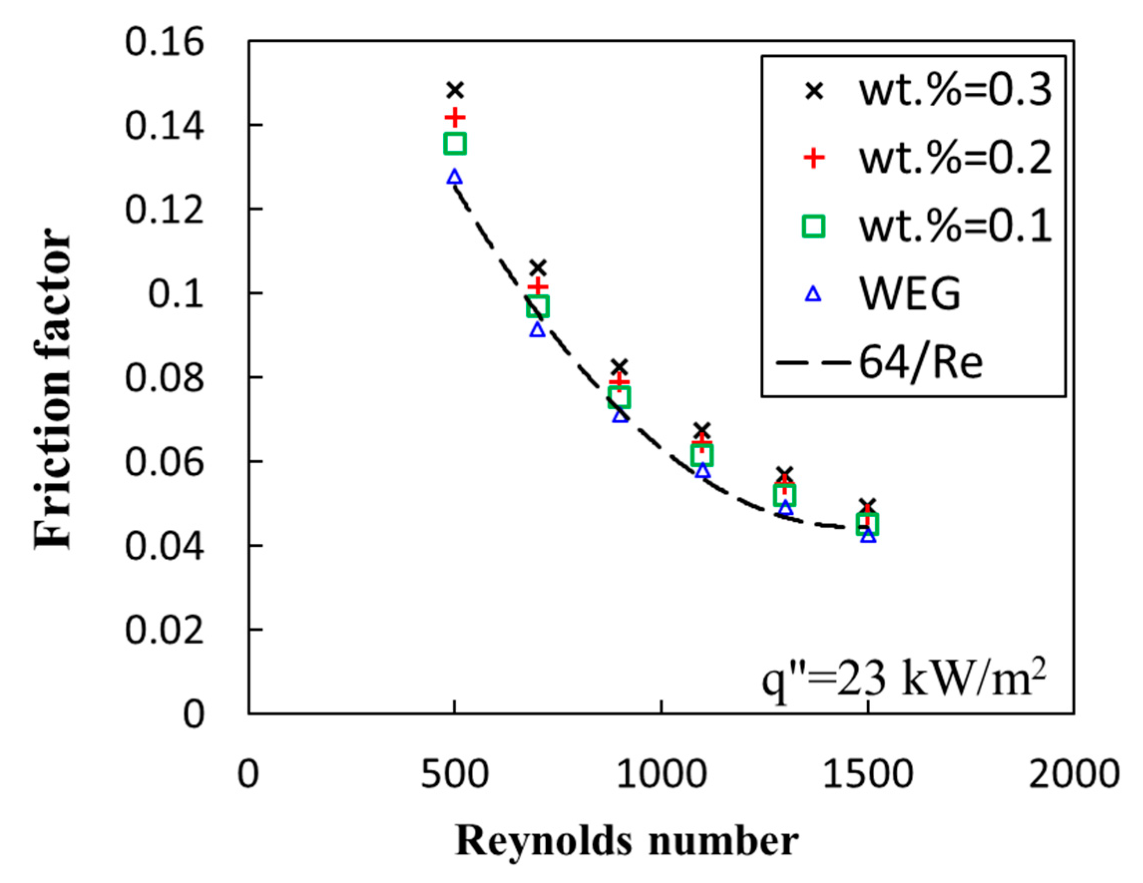
3.4. Pressure Drop and Friction Factor

Figure 6 displays the variation of the PD value with the Re at different mass fractions of NPGs. It is apparent that by increasing the fluid flow rate, the PD value of the system raises. As the system flow regime is laminar, the PD shows almost nonlinear behavior with the Reynolds number. For example, for WEG at Re = 500, the PD value augmented by 1%, while at Re = 1500, the PD augmented by 6% reaching 10.4 kPa. For nanofluids, with an increment in the mass fractions of NPGs, the PD value is more pronounced. As an example, for Re = 500, at wt. % = 0.1, the PD enhancement is 1.01, while at wt. % = 0.3 and for the same Re number, the PD value is 1.05. The largest PD enhancement was recorded for nanofluids at wt. % = 0.3 and for the highest Reynolds number of 1500, which was 1.12. The increase in the PD of the system can be ascribed to the friction forces increment within the system. This is because the presence of NPGs can potentially raise the nanofluid’s viscosity, which in turn increases the layer–layer friction forces. It is worth saying that there are some possibilities, such as the potential of agglomeration of the NPGs within the channels, which can temporarily block the fluid flow and increase the average PD. To understand this clearly, the friction factor of the system was also measured.
Figure 7 represents the variation of the friction factor of the system with Re for WEG and nanofluids at various mass fractions of NPGs. As is evident, the system follows the Darcy equation, 64/Re [54], the friction factor raises with an decrease in the Reynolds number of the system, and the trend of the augmentation is asymptotic. The lowest friction factor was also measured for the largest Reynolds number, regardless of the type of the working fluid, which was 0.042 for WEG and 0.049 for wt. % = 0.3. In addition, by adding more NPGs to the working fluid, the friction factor of the system was enlarged, which could be related to the boost in the viscosity and friction forces within the system. The augmentation in the friction forces was 6%, 11%, 16%, for wt. % = 0.1, 0.2, and 0.3, respectively. Thus, a trade-off can be identified between the enhancement in the HTC of the system and the friction forces boosting within the nanofluid. Therefore, there is a need to assess both the heat transfer enhancement and the augmentation of the PD to evaluate the performance of the system with nanofluids accurately. Briefly speaking, the presence of NPGs can increase the pumping power of the system as well. However, it does not necessarily mean that the GNP-WEG is not a suitable working fluid. Hence, thermal performance evaluation criteria should be employed to assess both the positive and negative impacts of NPGs on the thermal performance of the system simultaneously.

3.5. Thermal Performance Evaluation

Figure 8 illustrates the variation of the thermo–hydraulic performance of the system with Re and for nanofluids. At a short glance, it can be concluded that the thermal performance of the system enhances with the Reynolds number augmentation, such that the largest TPEC is recorded for the highest Reynolds number. In addition, with adding more nanomaterials to the nanofluids, the TPEC of the system boosts, despite the raise in the pressure drop value. This is because the HTC is enhanced anomalously, such that it can compensate the augmentation in the PD value of the system. For instance, at wt. % = 0.3 and Re = 500, the TPEC is 1.07, while at Re = 1500, the TPEC is promoted to 1.21. Also, at Re = 1500, at wt. % = 0.1, the TPEC is 1.07, while it is 1.21 at wt. % = 0.3. Considering the aforementioned discussion, it can be stated that GNP-WEG nanofluid can potentially improve the thermal performance of the heat exchanger, which is mainly owing to the improvement in the physical properties of the carrying fluid. It is worth saying that the present study only tested the performance of the system for a convective single-phase heat and fluid flow, however, further research is highly recommended to assess the GNP-WEG nanofluid in a two-phase heat and fluid flow condition.

4. Conclusions

In the present investigation, a series of experiments were conducted to evaluate the thermal performance of a micro-channel cooling system working with NPGs dispersed in WEG (60:40) and the subsequent conclusions were acquired:
1-
The thermal conductivity of the NPGs-WEG nanofluid enhanced with an increase in the mass fraction of the nanofluids. However, by increasing the temperature of the system, the thermal conductivity slightly increased. The highest increment in the thermal conductivity of GNP-WEG nanofluid was 32.1% at 50 °C and wt. % = 0.3.
2-
By increasing the heat-flux and the Reynolds number, the HTC of the system was improved. The improvement in the HTC was due to the increase in the mean temperature of the system and the enhancement of the thermos–physical properties of the nanofluids. Also, improvement in the Brownian motion and thermophoresis effects were two other contributors to the enhancement of the HTC.
3-
By adding more NPGs to the base fluid, the HTC was increased, which was ascribed to the improvement in the Brownian motion, a reduction in the mean free path, and also an increase in the number of collisions between the NPGs within the bulk of the nanofluid.
4-
A trade-off trend was identified between the HTC and the PD value of the system. However, despite the augmentation in the friction forces and the PD value, the enhancement in the HTC compensated the augmentation of the friction forces. To evaluate both effects, the TPEC of the system was measured and it was found that the largest TPEC belonged to the largest Reynolds number and the highest mass fraction of the nanofluid. The maximum TPEC of the system was 21% at wt. % = 0.3.
Overall, GNP-WEG presented a plausible thermal performance within the micro-channel, despite the augmentation in PD, and this nanofluid can plausibly be used in cooling and/or heating applications. It is worth saying that despite the plausible effect of the nano-particulate graphene nanofluid for enhancing the heat transfer, the contribution of this effect on conduction and the convection mechanisms is still unknown and it is highly recommended that a systematic study be developed to evaluate these contributions.

Author Contributions

Conceptualization, M.M.S., M.G., E.P.B.F. and M.R.S.; methodology E.P.B.F. and M.M.S., and M.G.; validation, E.P.B.F.; formal analysis, M.M.S., and Z.T.; investigation, M.M.S., E.P.B.F., and Z.T.; writing—original draft preparation, M.M.S., M.R.S.; writing—review and editing, M.M.S., M.A., M.R.S., Z.T. and M.G.; visualization, M.M.S. and Z.T.; supervision, M.A. and M.M.S.; project administration, M.A.

Funding

Zhe Tian wants to acknowledge the following grants: NSFC (51,709,244), Taishan Scholar (tsqn201812025), and Fundamental Research for Central Universities (201,941,008).

Acknowledgments

Authors of this work appreciate the University of Adelaide for the facility.

Conflicts of Interest

The authors declare no conflict of interest.

References

  1. Shah, R.K.; Sekulic, D.P. Fundamentals of Heat Exchanger Design; John Wiley & Sons: Hoboken, NJ, USA, 2003. [Google Scholar]
  2. Bejan, A. The concept of irreversibility in heat exchanger design: Counterflow heat exchangers for gas-to-gas applications. J. Heat Transf. 1977, 99, 374–380. [Google Scholar] [CrossRef]
  3. Rohsenow, W.M.; Hartnett, J.P.; Ganic, E.N. Handbook of Heat Transfer Applications; No Individual Items are Abstracted in This Volume; McGraw-Hill Book Co.: New York, NY, USA, 1985; 973p. [Google Scholar]
  4. Sundén, B.; Manglik, R.M. Plate Heat Exchangers: Design, Applications and Performance; Wit Press: England, UK, 2007; Volume 11. [Google Scholar]
  5. Master, B.I.; Chunangad, K.S.; Boxma, A.; Kral, D.; Stehlik, P. Most frequently used heat exchangers from pioneering research to worldwide applications. Heat Transf. Eng. 2006, 27, 4–11. [Google Scholar] [CrossRef]
  6. Kays, W.M.; London, A.L. Compact Heat Exchangers; Krieger Publishing: Malabar, FL, USA, 1984. [Google Scholar]
  7. Hesselgreaves, J.E.; Law, R.; Reay, D. Compact Heat Exchangers: Selection, Design and Operation; Butterworth-Heinemann: Oxford, UK, 2016. [Google Scholar]
  8. Khan, M.G.; Fartaj, A. A review on micro-channel heat exchangers and potential applications. Int. J. Energy Res. 2011, 35, 553–582. [Google Scholar] [CrossRef]
  9. Choi, S.U.; Eastman, J.A. Enhancing Thermal Conductivity of Fluids with Nanoparticles; Argonne National Lab.: DuPage County, IL, USA, 1995. [Google Scholar]
  10. Arya, A.; Sarafraz, M.; Shahmiri, S.; Madani, S.; Nikkhah, V.; Nakhjavani, S. Thermal performance analysis of a flat heat pipe working with carbon nanotube-water nanofluid for cooling of a high heat-flux heater. Heat Mass Transf. 2018, 54, 985–997. [Google Scholar] [CrossRef]
  11. Nakhjavani, M.; Nikkhah, V.; Sarafraz, M.; Shoja, S.; Sarafraz, M. Green synthesis of silver nanoparticles using green tea leaves: Experimental study on the morphological, rheological and antibacterial behaviour. Heat Mass Transf. 2017, 53, 3201–3209. [Google Scholar] [CrossRef]
  12. Nikkhah, V.; Sarafraz, M.; Hormozi, F. Application of spherical copper oxide (II) water nano-fluid as a potential coolant in a boiling annular heat exchanger. Chem. Biochem. Eng. Q. 2015, 29, 405–415. [Google Scholar] [CrossRef]
  13. Salari, E.; Peyghambarzadeh, M.; Sarafraz, M.M.; Hormozi, F. Boiling heat transfer of alumina nano-fluids: Role of nanoparticle deposition on the boiling heat transfer coefficient. Period. Polytech. Chem. Eng. 2016, 60, 252–258. [Google Scholar] [CrossRef]
  14. Sarafraz, M.; Hormozi, F.; Peyghambarzadeh, S.; Vaeli, N. Upward Flow Boiling to DI-Water and Cuo Nanofluids Inside the Concentric Annuli. J. Appl. Fluid Mech. 2015, 8, 651–659. [Google Scholar]
  15. Sarafraz, M.; Hormozi, F.; Silakhori, M.; Peyghambarzadeh, S. On the fouling formation of functionalized and non-functionalized carbon nanotube nano-fluids under pool boiling condition. Appl. Therm. Eng. 2016, 95, 433–444. [Google Scholar] [CrossRef]
  16. Sarafraz, M.; Nikkhah, V.; Madani, S.; Jafarian, M.; Hormozi, F. Low-frequency vibration for fouling mitigation and intensification of thermal performance of a plate heat exchanger working with CuO/water nanofluid. Appl. Therm. Eng. 2017, 121, 388–399. [Google Scholar] [CrossRef]
  17. Sarafraz, M.; Nikkhah, V.; Nakhjavani, M.; Arya, A. Thermal performance of a heat sink micro-channel working with biologically produced silver-water nanofluid: Experimental assessment. Exp. Therm. Fluid Sci. 2018, 91, 509–519. [Google Scholar] [CrossRef]
  18. Sarafraz, M.; Peyghambarzadeh, S. Nucleate pool boiling heat transfer to Al2O3-water and TiO2-water nanofluids on horizontal smooth tubes with dissimilar homogeneous materials. Chem. Biochem. Eng. Q. 2012, 26, 199–206. [Google Scholar]
  19. Sarafraz, M.; Peyghambarzadeh, S.; Alavi Fazel, S.; Vaeli, N. Nucleate Pool Boiling Heat Transfer of Binary Nano Mixtures under Atmospheric Pressure around a Smooth Horizontal Cylinder. Period. Polytech. Chem. Eng. 2013, 57, 71–77. [Google Scholar] [CrossRef]
  20. Bowers, J.; Cao, H.; Qiao, G.; Li, Q.; Zhang, G.; Mura, E.; Ding, Y. Flow and heat transfer behaviour of nanofluids in micro-channels. Prog. Nat. Sci. Mater. Int. 2018, 28, 225–234. [Google Scholar] [CrossRef]
  21. Manay, E.; Sahin, B. The effect of micro-channel height on performance of nanofluids. Int. J. Heat Mass Transf. 2016, 95, 307–320. [Google Scholar] [CrossRef]
  22. Radwan, A.; Ahmed, M.; Ookawara, S. Performance enhancement of concentrated photovoltaic systems using a micro-channel heat sink with nanofluids. Energy Convers. Manag. 2016, 119, 289–303. [Google Scholar] [CrossRef]
  23. Zhang, C.; Zhang, L.; Xu, H.; Wang, D.; Ye, B. Investigation of flow boiling performance and the resulting surface deposition of graphene oxide nanofluid in micro-channels. Exp. Therm. Fluid Sci. 2017, 86, 1–10. [Google Scholar] [CrossRef]
  24. Xia, G.; Liu, R.; Wang, J.; Du, M. The characteristics of convective heat transfer in micro-channel heat sinks using Al2O3 and TiO2 nanofluids. Int. Commun. Heat Mass Transf. 2016, 76, 256–264. [Google Scholar] [CrossRef]
  25. Anbumeenakshi, C.; Thansekhar, M. On the effectiveness of a nanofluid cooled micro-channel heat sink under non-uniform heating condition. Appl. Therm. Eng. 2017, 113, 1437–1443. [Google Scholar] [CrossRef]
  26. Sarafraz, M.; Nikkhah, V.; Nakhjavani, M.; Arya, A. Fouling formation and thermal performance of aqueous carbon nanotube nanofluid in a heat sink with rectangular parallel micro-channel. Appl. Therm. Eng. 2017, 123, 29–39. [Google Scholar] [CrossRef]
  27. Abdollahi, A.; Mohammed, H.; Vanaki, S.M.; Osia, A.; Haghighi, M.G. Fluid flow and heat transfer of nanofluids in micro-channel heat sink with V-type inlet/outlet arrangement. Alex. Eng. J. 2017, 56, 161–170. [Google Scholar] [CrossRef]
  28. Bahiraei, M.; Jamshidmofid, M.; Goodarzi, M. Efficacy of a hybrid nanofluid in a new micro-channel heat sink equipped with both secondary channels and ribs. J. Mol. Liq. 2019, 273, 88–98. [Google Scholar] [CrossRef]
  29. Saini, A.; Sandhu, H.; Sharma, S.; Dasaroju, G. Study of Heat Transfer of Aluminium Oxide Nanofluids using Aluminium Split Flow Micro-channels. Int. J. Eng. Res. Technol. (Ijert) 2016, 5, 277–285. [Google Scholar]
  30. Kalteh, M.; Abbassi, A.; Saffar-Avval, M.; Frijns, A.; Darhuber, A.; Harting, J. Experimental and numerical investigation of nanofluid forced convection inside a wide micro-channel heat sink. Appl. Therm. Eng. 2012, 36, 260–268. [Google Scholar] [CrossRef]
  31. Manay, E.; Sahin, B. Heat transfer and pressure drop of nanofluids in a micro-channel heat sink. Heat Transf. Eng. 2017, 38, 510–522. [Google Scholar] [CrossRef]
  32. Wu, X.; Wu, H.; Cheng, P. Pressure drop and heat transfer of Al2O3-H2O nanofluids through silicon micro-channels. J. Micromech. Microeng. 2009, 19, 105020. [Google Scholar] [CrossRef]
  33. Thansekhar, M.R.; Anbumeenakshi, C. Experimental investigation of thermal performance of micro-channel heat sink with nanofluids Al2O3/water and SiO2/water. Exp. Tech. 2017, 41, 399–406. [Google Scholar] [CrossRef]
  34. Ting, T.W.; Hung, Y.M.; Guo, N. Viscous dissipative nanofluid convection in asymmetrically heated porous micro-channels with solid-phase heat generation. Int. Commun. Heat Mass Transf. 2015, 68, 236–247. [Google Scholar] [CrossRef]
  35. Halelfadl, S.; Adham, A.M.; Mohd-Ghazali, N.; Maré, T.; Estellé, P.; Ahmad, R. Optimization of thermal performances and pressure drop of rectangular micro-channel heat sink using aqueous carbon nanotubes based nanofluid. Appl. Therm. Eng. 2014, 62, 492–499. [Google Scholar] [CrossRef]
  36. Ghadirzadeh, S.; Kalteh, M. Lattice Boltzmann simulation of temperature jump effect on the nanofluid heat transfer in an annulus micro-channel. Int. J. Mech. Sci. 2017, 133, 524–534. [Google Scholar] [CrossRef]
  37. Parsaiemehr, M.; Pourfattah, F.; Akbari, O.A.; Toghraie, D.; Sheikhzadeh, G. Turbulent flow and heat transfer of Water/Al2O3 nanofluid inside a rectangular ribbed channel. Phys. E Low-Dimens. Syst. Nanostructures 2018, 96, 73–84. [Google Scholar] [CrossRef]
  38. Farsad, E.; Abbasi, S.P.; Zabihi, M.S.; Sabbaghzadeh, J. Numerical simulation of heat transfer in a micro channel heat sinks using nanofluids. Heat Mass Transf. 2011, 47, 479–490. [Google Scholar] [CrossRef]
  39. Singh, B.; Singh, M.; Garg, H.; Kaur, I.; Suryavanshi, S.; Kumar, H. Experimental and numerical analysis of micro-scale heat transfer using carbon based nanofluid in micro-channel for enhanced thermal performance. In IOP Conference Series: Materials Science and Engineering; IOP Publishing: Bristol, UK, 2016; Volume 149, p. 12200. [Google Scholar]
  40. Behnampour, A.; Akbari, O.A.; Safaei, M.R.; Ghavami, M.; Marzban, A.; Shabani, G.A.S.; Mashayekhi, R. Analysis of heat transfer and nanofluid fluid flow in micro-channels with trapezoidal, rectangular and triangular shaped ribs. Phys. E: Low-Dimens. Syst. Nanostructures 2017, 91, 15–31. [Google Scholar] [CrossRef]
  41. Mohsenian, S.; Ramiar, A.; Ranjbar, A.A. Numerical investigation of non-Newtonian nanofluid flow in a converging micro-channel. J. Mech. Sci. Technol. 2017, 31, 385–391. [Google Scholar] [CrossRef]
  42. Liou, T.-M.; Wei, T.-C.; Wang, C.-S. Investigation of nanofluids on heat transfer enhancement in a louvered micro-channel with lattice Boltzmann method. J. Therm. Anal. Calorim. 2019, 135, 751–762. [Google Scholar] [CrossRef]
  43. Yu, W.; Xie, H. A review on nanofluids: Preparation, stability mechanisms, and applications. J. Nanomater. 2012, 2012, 1. [Google Scholar] [CrossRef]
  44. Choi, S.U. Nanofluids: From vision to reality through research. J. Heat Transf. 2009, 131, 033106. [Google Scholar] [CrossRef]
  45. Chabi, A.; Zarrinabadi, S.; Peyghambarzadeh, S.; Hashemabadi, S.; Salimi, M. Local convective heat transfer coefficient and friction factor of CuO/water nanofluid in a micro-channel heat sink. Heat Mass Transf. 2017, 53, 661–671. [Google Scholar] [CrossRef]
  46. Sarafraz, M.M.; Arjomandi, M. Thermal performance analysis of a microchannel heat sink cooling with Copper Oxide-Indium (CuO/In) nano-suspensions at high-temperatures. Appl Therm Eng. 2018, 137, 700–709. [Google Scholar] [CrossRef]
  47. Azizi, Z.; Alamdari, A.; Malayeri, M.R. Convective heat transfer of Cu–water nanofluid in a cylindrical micro-channel heat sink. Energy Convers. Manag. 2015, 101, 515–524. [Google Scholar] [CrossRef]
  48. Ravi Kumar, H.K.V.K.N.A.B.M. A Comprehensive Study of Modified Wilson Plot Technique to Determine the Heat Transfer Coefficient during Condensation of Steam and R-134a over Single Horizontal Plain and Finned Tubes. Heat Transf. Eng. 2001, 22, 3–12. [Google Scholar] [CrossRef]
  49. Sarafraz, M.M.; Arya, A.; Hormozi, F.; Nikkhah, V. On the convective thermal performance of a CPU cooler working with liquid gallium and CuO/water nanofluid: A comparative study. Appl. Therm. Eng. 2017, 112, 1373–1381. [Google Scholar] [CrossRef]
  50. Kline, S.; McClintock, F.A. Describing Uncertainties in Single-Sample Experiments. Mech. Eng. 1953, 75, 3–8. [Google Scholar]
  51. Karatzas, I.; Shreve, S.E. Brownian motion. In Brownian Motion and Stochastic Calculus; Springer: Berlin, Gemany, 1998; pp. 47–127. [Google Scholar]
  52. Haddad, Z.; Abu-Nada, E.; Oztop, H.F.; Mataoui, A. Natural convection in nanofluids: Are the thermophoresis and Brownian motion effects significant in nanofluid heat transfer enhancement? Int. J. Therm. Sci. 2012, 57, 152–162. [Google Scholar] [CrossRef]
  53. Browning, L.M.; Lee, K.J.; Huang, T.; Nallathamby, P.D.; Lowman, J.E.; Xu, X.-H.N. Random walk of single gold nanoparticles in zebrafish embryos leading to stochastic toxic effects on embryonic developments. Nanoscale 2009, 1, 138–152. [Google Scholar] [CrossRef]
  54. Tek, M. Development of a generalized Darcy equation. J. Pet. Technol. 1957, 9, 45–47. [Google Scholar] [CrossRef]
Figure 1. Experimental device used in this work, (A) image of the test rig, (B) Image of the micro-channel and its schematic diagram.
Energies 12 01929 g001aEnergies 12 01929 g001b
Figure 2. (A) Preparation of the nanofluids and the results of the characterisation tests, including X-ray diffraction test (XRD), scanning electron microscopy (SEM), and particle-size test (PSC) conducted on the graphene particles. (B) Thermal conductivity of the GNP/WEG nanofluids (the enhancement percentages are the average enhancement for various temperatures at a given mass fraction).
Energies 12 01929 g002
Figure 3. Variation of the heat-transfer coefficient (HTC) of the system with the uniform applied heat-flux for WEG and nanofluid at wt. % = 0.1.
Energies 12 01929 g003
Figure 4. Variation of the HTC of the system with Reynolds number.
Energies 12 01929 g004
Figure 5. Variation of the HTC of the system with heat-flux at various mass fractions of NPGs.
Energies 12 01929 g005
Figure 6. Dependence of the pressure drop (PD) value of the system on the fluid flow rate for WEG and nanofluids at various mass fractions.
Energies 12 01929 g006
Figure 7. Variation of the friction factor with Reynolds number for WEG and nanofluids.
Energies 12 01929 g007
Figure 8. Variation of the thermal performance evaluation criteria (TPEC) with Reynolds number (Re) for nanofluids at various mass fractions.
Energies 12 01929 g008
Table 1. A summary of works conducted on the thermal performance of the nanofluids in micro-channel heat-exchanging systems.
Authors’ NamesType of study (Numerical or Experimental)Cross-SectionType of NanofluidAverage Size of Nanoparticles/NanomaterialsEnhancement (%)
Bahiraei et al. [28]NumericalRectangularGraphene nano-platelets –silver/waterDiameter: 2 µm17
Saini et al. [29]ExperimentalRectangularAl2O3/water80 nm27
Kalteh et al. [30]Experimental and NumericalRectangularAl2O3/water40 nm130
Manay and Sahin [31]ExperimentalRectangularTiO2/water25 nm39.7
Wu et al. [32]ExperimentalTrapezoidalAl2O3/water56 nm15.8
Thansekhar and Anbumeenakshi [33] ExperimentalRectangularAl2O3/water43 nm32.79
SiO2/water13.89
Ting et al. [34]AnalyticalRectangularAl2O3/water40 nm70
Halelfadl et al. [35]Analytical and experimentalRectangularCNT/waterDiameter: 9–10 nm
Length: 15 µm
13
Ghadirzadeh and Kalteh [36]NumericalAnnulusAl2O3/water10–100 nm18.6
Parsaiemehr et al. [37]NumericalRectangular ribbedAl2O3/water50 nm237
Farsad et al. [38]NumericalRectangularAl2O3/water11 nm4.5
CuO/water-
Cu/water-
Singh et al. [39]Experimental and NumericalRectangularCNT/water 200
Behnampour et al. [40]NumericalTrapezoidal Rectangular TriangularAg/water50 nm100
Mohsenian et al. [41]NumericalConverging micro-channelTiO2/water10 nm90
Liou et al. [42]Numericallouvered micro-channelAl2O3/water47 nm70

