Article

A Control Algorithm for the Novel Regenerative–Mechanical Coupled Brake System with by-Wire Based on Multidisciplinary Design Optimization for an Electric Vehicle

College of Engineering, China Agricultural University, Beijing 100083, China
*
Author to whom correspondence should be addressed.
Energies 2018, 11(9), 2322; https://doi.org/10.3390/en11092322
Submission received: 15 August 2018 / Revised: 30 August 2018 / Accepted: 30 August 2018 / Published: 3 September 2018

Abstract

:
Current regenerative braking systems in electric vehicles have several problems, such as complex structures, too many control parameters, and inconsistent braking responses. To solve these problems, a control algorithm with multidisciplinary design optimization (MDO) is proposed based on the novel regenerative–mechanical coupled brake-by-wire system. A dynamic model of the novel regenerative braking system was established to analyze the mechanism of coupled braking and propose a braking torque distribution strategy. To realize a better balance between the optimum braking stability and the maximum regenerative energy recovery based on the braking torque distribution strategy and sample points, the MDO mathematical model was developed to optimize the control parameters with the collaborative optimization algorithm. The finite sample points comprising the vehicle speed, battery state-of-charge, and braking severity were obtained through an optimal Latin hypercube design and represent the overall design space. A network was established based on the sample points and the optimization results. Using this network, the in-depth characteristics of the sample points and the optimization results were obtained through supervised learning to develop the control algorithm for vehicle braking. A simulation was performed using the normal braking condition, and the simulation results demonstrated that the control algorithm has higher control precision than conventional methods and better real-time performance than online optimization.

1. Introduction

Electric vehicles (EVs) have received significant attention because of the global environmental crisis and pressure on energy sources. Compared to conventional vehicles, electric vehicles can recapture kinetic energy during deceleration using a regenerative braking system without requiring any additional components [1]. A regenerative braking system can recover kinetic energy into a battery through an electric motor, which is also used to produce a regenerative braking torque to the wheels to realize braking [2]. Research shows that more than half of the braking energy can potentially be used in typical urban driving cycles [3]. Hence, to improve the energy efficiency, regenerative braking and friction braking cooperative systems are widely used in EVs [4]. In a cooperative braking system, two types of regenerative braking control strategies are used: series and parallel. In the parallel strategy, the regenerative braking torque is added into the friction braking torque at a fixed proportion. In the series strategy, the proportion of the regenerative braking torque and the friction braking torque can be modulated to control the overall braking torque for meeting the requirements [5]. The regenerative braking torque depends on the motor characteristics [6], the charging power capability of the battery [7], and the available tire–road friction [8]; hence, existing research has focused on improving the braking energy recovery efficiency by distributing the torque between regenerative braking and friction braking based on drivers’ demands.
In engineering practice, several rule-based regenerative braking strategies have been proposed and used in recent years. For a rear-driven electric truck, a modified control strategy that determines how to distribute the braking force between the front and rear axles was proposed by Zhang to improve the recovery efficiency [9]. Xiao presented an integrated control strategy to coordinate regenerative and friction braking forces to deal with the braking stability and recovery efficiency when a vehicle performed normal deceleration and emergency braking [3]. To regenerate more braking energy and move closer to the ideal braking force distribution curve, a combined braking control strategy was developed for the rear wheel-driven series hybrid electric EV to adjust the proportions of regenerative braking and friction braking [10]. A regenerative braking cooperative control strategy was proposed by Jiweon for hybrid EVs equipped with a hydraulic brake on the rear wheels and an electronic wedge brake on the front wheels [11].
Optimization and control technologies have also been proposed to control the cooperative braking system. A genetic algorithm-based control strategy that determines how to distribute the brake torque between regenerative braking and electrohydraulic braking was developed by Kim [12]. Furthermore, to control the wheel slip, a sliding-mode controller was designed by Zhang to distribute the braking force between regenerative braking and antilock braking in emergency braking situations [13]. Fuzzy logic was applied in brake energy recovery systems. Compared to the conventional control strategy, the fuzzy logic control strategy presents a higher recovery efficiency in regenerative braking [14]. A sliding-mode controller based on the exponential reaching law for the antilock braking system was developed. The tracking of the slip ratio became rapid and accurate in adjusting the motor braking moment with the proposed sliding-mode controller [15]. A nonlinear-model predictive controller for regenerative braking control in EVs equipped with in-wheel motors was presented [16]. A control algorithm based on a model predictive control framework was proposed to recover more braking energy and maintain the optimal slip value. The framework could reduce the torque tracking error [17].
The feasibility of several control strategies is worth studying, and the optimization of control parameters that affect the comprehensive braking performance, including braking stability and energy recuperation efficiency, also needs attention. Sun presented a predictive control strategy using an offline process optimization stream to realize the balance between the maximum regenerative energy recuperation efficiency and the optimum braking stability [18,19]. However, a problem of inconsistent braking response exists because regenerative braking and friction braking are two independent systems. In addition, some sampling points have a large predictive error when using conventional approximation models because of the highly nonlinear relationship between sampling points and predictive values.
As evidenced in the literature survey, several problems exist, such as complex structures, too many control parameters, and inconsistent braking response, because current braking systems comprise two independent systems, the regenerative and friction braking systems. It is difficult to maintain good regenerative braking efficiency and regenerative braking effectiveness stability because it is necessary to switch between the regenerative braking system and the friction braking system during braking. Moreover, a strong coupling relationship exists between the regenerative system and the friction braking system. Obtaining a good comprehensive braking performance using conventional optimization methods is difficult. To solve these problems, first, the mathematical model of the novel regenerative–mechanical coupled brake-by-wire system is presented herein to reveal the coupled braking mechanism. Next, two disciplines, namely the optimum braking stability and the maximum regenerative energy recovery efficiency, are defined to optimize the comprehensive braking performance of the vehicle. The optimization results are obtained using a collaborative optimization algorithm. Thereafter, a network is built based on the optimization results and the sample points comprising the vehicle speed v, battery state-of-charge (SoC), and braking severity z. Afterwards, through supervised learning, the in-depth characteristics of the sample points and the optimization results are obtained based on the deep learning network to establish the deep learning control algorithm. Finally, the deep learning control algorithm is verified to have higher control precision than conventional methods and a better real-time performance than online optimization in a dynamic simulation.
This paper is organized as follows: Section 2 describes the mechanism of the novel regenerative–mechanical coupled brake-by-wire system; 
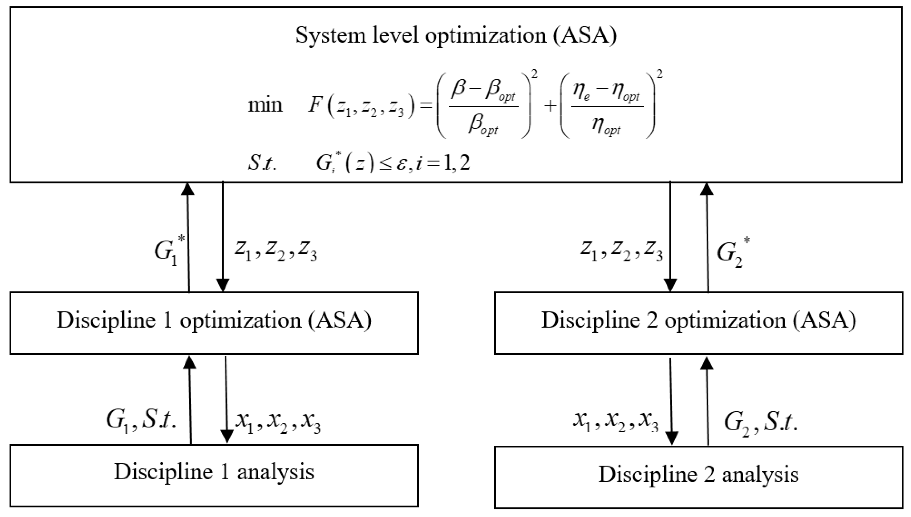
Section 3 presents a mathematical optimization model and describes the multidisciplinary design optimization (MDO) method for optimizing the control parameters of the novel regenerative–mechanical coupled brake-by-wire system; Section 4 presents a deep learning control algorithm based on the optimization results and sample points obtained using a deep learning network, and Section 5 presents the simulations, followed by the concluding remarks in the final section.

2. Novel Regenerative–Mechanical Coupled Brake-by-Wire System

2.1. Structure of the Novel Regenerative–Mechanical Coupled Brake-by-Wire System

The novel regenerative–mechanical coupled brake-by-wire system, which takes advantage of brake-by-wire and regenerative braking [20,21], is built based on the mechanism of mechanical-electrical-magnetic energy conversion (
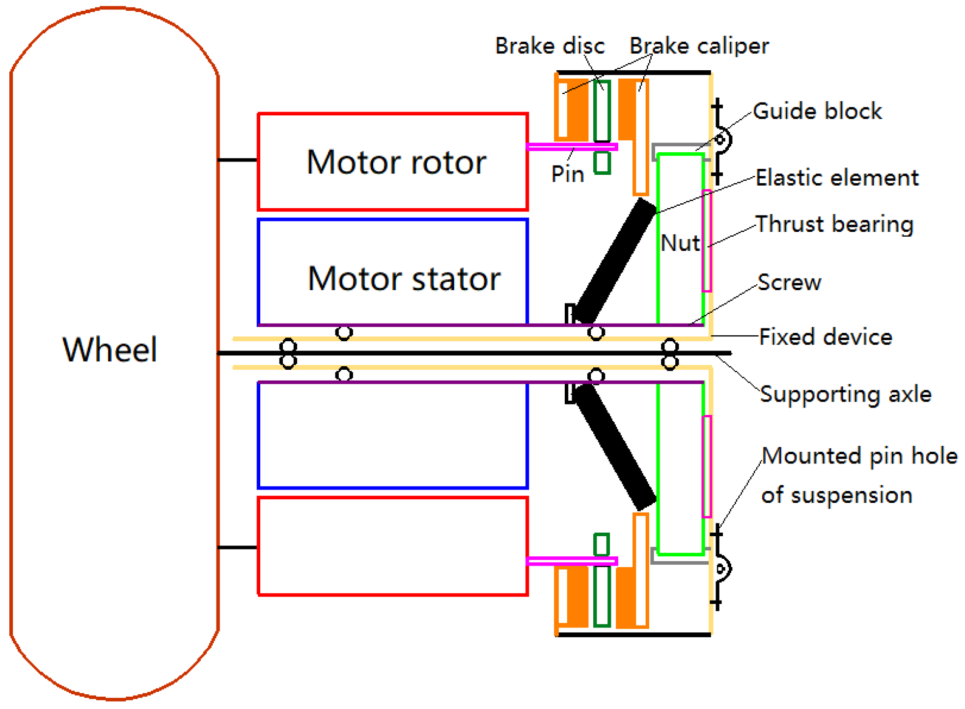
Figure 1).
As shown in Figure 1, during braking, the in-wheel motors equipped on the front and rear wheels perform regenerative braking and recover kinetic energy into the battery. The transmission path of the regenerative braking torque is as follows: motor stator motor rotor wheel.
The screw is fixed on the motor stator; hence, when the electromagnetic torque generated by the motor stator is transmitted to the screw, the motive force of friction braking will be converted to generative friction braking torque. The transmission path of the regenerative braking torque is as follows: motor stator screw and nut elastic element brake caliper and brake disc motor rotor wheel.
The electromagnetic torque generated by the feedback current performs braking in the novel regenerative–mechanical coupled brake-by-wire system. At the same time, the friction braking torque can be generated by the electromagnetic braking torque, which is the driving force for friction braking, without additional energy consumption. The coupled braking process involving regenerative braking and friction braking is then realized. Hence, the electromagnetic torque can be controlled to modulate the braking severity and maintain the optimum comprehensive performance in terms of energy recovery and braking stability through mechanical/electrical/magnetic MDO.
This study focuses on the normal deceleration process that has a braking severity ranging from 0 to 0.4 with enough adhesive force from the dry pavement. Considering the characteristics of both motor and battery, the vehicle speed is limited within 10 km/h to 100 km/h, and the battery SoC is a value in the range of 0.2–0.8.

2.2. Mathematical Model of the Novel Regenerative–Mechanical Coupled Brake-by-Wire System

During braking, the electromagnetic torque T e between the motor rotor and the motor stator is generated by the feedback current I L in the motor rotor coil under the effect of electromagnetic induction. The regenerative braking torque T b e is then generated by T e in the brake wheels through the connection device. Neglecting the tube pressure drop of the feedback brake circuit and the motor self-friction torque in the steady state, T e and T b e can be expressed as follows [22]:
{ T e = K e I L T b e = T e
where K e is the torque coefficient (Nm/A).
As shown in Figure 1, the screw cannot slide, but can only rotate along with the motor stator. The nut cannot rotate, but can only slide along with the guide block. The screw and the nut are joined by a non-locking spiral. The screw is fixed to the motor stator; hence, the thrust force F N can be generated by the electromagnetic torque through the transmission mechanism. F N can be expressed as follows [23]:
F N = η 1 T e R c tan ( α s + ρ s )
where η 1 is the mechanical efficiency of the transmission mechanism; R c is the friction radius of the screw end plane (m); α s is the lead angle of the screw (rad); and ρ s is the equivalent friction angle of the screw and the nut (rad).
When F N overcomes the elastic force F s of the elastic element, the friction braking torque will be generated by the brake caliper in the clamping brake disc and transmitted to the brake wheels through the motor rotor and connection device. The friction braking torque T b c is then described as follows:
T b c = 2 i c μ c R p F c
where F c = max ( F N F s , 0 ) , i c is the transmission ratio of the transmission mechanism; μ c is the friction coefficient of the brake disc, and R p is the radius of the brake pressure (m).
Therefore, T b c can be generated by T e in the novel regenerative–mechanical coupled brake-by-wire system, and T b c can be coupled with T b e to the brake wheels. The total braking torque T b can then be described as follows:
T b = T b e + T b c
As Equations (1)–(4) show, compared to the current braking systems that comprise two independent systems, namely the regenerative and friction braking systems, the novel regenerative–mechanical coupled brake-by-wire system can realize optimal dynamic matching between the regenerative torque and the friction torque and a brake-by-wire coupling of regenerative braking and friction braking. The integration of the entire braking system is considerably improved, and its structure is simplified.

2.3. Braking Torque Distribution Strategy

The research object is a distributed four-wheel-drive EV. Based on longitudinal braking dynamics in straight-line travel, the braking force provided by the ground, regenerative braking torque, and friction braking torque on the left and right wheels of the front axle are equal, and so are the torques on the left and right wheels of the rear axle.
The torques of each wheel can be expressed as follows:
{ T b e 1 + T b e 2 = T H b e 2 T b c 1 + T b c 2 = T H b c 2 F x b 1 = T b e 1 + T b c 1 R e F x b 2 = T b e 2 + T b c 2 R e T H b e + T H b c = T H b T H b = m g z R e
where T b e 1 and T b e 2 are the regenerative braking torques on the left wheel of the front and rear axles, respectively (Nm); T H b e is the total regenerative braking torque (Nm); T b c 1 and T b c 2 are the friction braking torques on the left wheel of the front and rear axles, respectively (Nm); T H b c is the total friction braking torque (Nm); F x b 1 and F x b 2 are the tire-ground braking forces on the left wheel of the front and rear axles, respectively (N); R e is the effective tire radius (m); T H b is the total braking torque (Nm); m is the kerb mass (kg); g is the acceleration caused by gravity (m/s2), and z is the braking severity.
The braking torque distribution strategy aiming at an optimal overall performance in terms of the braking stability and the regenerative braking energy recovery rate is proposed for a novel regenerative–mechanical coupled brake-by-wire system. The strategy can be described as follows:
First, the proportion of the total regenerative braking torque in the overall braking torque is determined as follows:
2 ( T b e 1 + T b e 2 ) T H b = α
where α is the distribution coefficient of the regenerative braking torque.
Second, the proportion of the regenerative braking torque between the front and rear axles is determined as follows:
2 T b e 1 T H b e = γ
where γ is the distribution coefficient of the regenerative braking torque on the front axle.
Third, the proportion of the friction braking torque between the front and rear axles is determined as follows:
2 T b c 1 T H b c = λ
where λ is the distribution coefficient of the friction braking torque on the front axle.
Combining Equations (5)–(8) gives the following:
{ T b e 1 = α γ m g z R e 2 T b e 2 = α ( 1 γ ) m g z R e 2 T b c 1 = ( 1 α ) λ m g z R e 2 T b c 2 = ( 1 α ) ( 1 λ ) m g z R e 2
The braking force distribution coefficient β is defined as follows:
β = 2 ( T b e 1 + T b c 1 ) T H b = α ( γ λ ) + λ

3. Mathematical Optimization Models of the Novel Regenerative–Mechanical Coupled Brake-by-Wire System

3.1. Optimization Objectives

From the perspective of driving safety and energy economy, the optimum braking stability and the maximum regenerative energy recovery efficiency are treated as optimization objectives based on the novel regenerative–mechanical coupled brake-by-wire system discussed in this paper.

3.1.1. Ideal Braking Stability Objective

During braking, if the braking force is distributed in the form of an I curve, any wheel locking in advance will be prevented, and the optimum braking stability will be obtained [10,24]. The ideal braking force distribution, which is the goal of optimum braking stability, can be expressed as follows:
{ μ f = μ r μ f = 2 F x b 1 F z 1 μ r = 2 F x b 2 F z 2 β = F x b 1 F x b 1 + F x b 2
where μ f and μ r are the utilization of adhesion coefficients on the front and rear axles, respectively, and F z 1 and F z 2 are the front and rear axle loads, respectively (N).
According to the braking theory, F z 1 and F z 2 can be expressed as follows:
{ F z 1 = m g L ( L r + z h g ) F z 2 = m g L ( L f z h g )
where L is the axle base (m); L r is the rear axle to mass center distance (m); h g is the height of the mass center (m), and L f is the front axle to mass center distance (m).
Combining Equations (11) and (12), the optimum braking stability, which is the ideal braking force distribution, can be obtained as follows:
β o p t = ( L r + z h g ) L

3.1.2. Ideal Regenerative Energy Recovery Efficiency Objective

The braking energy recovery efficiency η e can generally be defined as the proportion of battery-stored energy, which is produced by motors, and total vehicle braking loss energy during the regenerative braking process [25].
η e = 0 t ( T e ω m η m P i n v P b a t ) d t E V + E J
where η e is a value in the range of 0–1; ω m is the motor speed (rad/s); η m is the charging efficiency of the motor; P i n v is the loss power of the inverters (KW); P b a t is the loss power during battery recharge (KW); t is the braking time (s), and E V and E J are the total kinetic energy losses in the translational and rotational motions of the vehicle, respectively (J).
On the premise of meeting the requirements of braking severity, the maximum braking energy recovery efficiency η o p t is reached when the total energy lost during vehicle braking is completely recovered and stored in the battery.
η o p t = 1

3.2. Boundary Conditions

3.2.1. Braking Stability Constraints

Based on braking theory [24], the braking stability can be obtained when the utilization of adhesion coefficient on the rear axle is lesser than or equal to that on the front axle.
μ r μ f
Therefore, the braking force distribution coefficient is limited, and can be expressed as follows:
β β o p t = ( L r + z h g ) L ; 0 z 0.8
The braking force distribution coefficient should also be limited based on braking regulations. The limits of the braking force distribution based on the braking regulation ZBT 24007-1989 can be expressed as follows [19]:
{ β L r + z h g L ( 0 z 0.3 ) ( z 0.08 ) ( L r + z h g ) z L < β ( z + 0.08 ) ( L r + z h g ) z L ( 0.15 z 0.3 ) β 1 ( z + 0.25 ) L 0.74 ( L f z h g ) z ( 0.3 z 0.8 ) 1 ( L f z h g ) ( z 0.1 0.85 + 0.2 ) z L β ( z h g + L r ) ( z 0.1 0.85 + 0.2 ) z L ( 0.2 z 0.8 )

3.2.2. Electromagnetic Torque Constraints

During regenerative braking, as shown in Equations (1) and (14), the electromagnetic torque, which affects the regenerative braking torque and the regenerative braking energy recovery efficiency, is simultaneously limited by the motor speed, battery SoC, and braking severity. Therefore, the electromagnetic torque can be defined as follows:
0 T e i min ( T m a x , T b a t t e r y )
where i = 1 , 2 ; T m a x is the maximum charge torque of the motor (Nm); T b a tter y is the maximum rechargeable torque of the battery (Nm); and T m a x and T b a tter y can be obtained from Equations (20) and (21), respectively.
T m a x = f T e ( n ) η m
where n is the motor speed (r/min); f T e ( n ) is the charging torque of the motors; f T e ( n ) can be obtained from the relationship curve of n vs. f T e ( n ) through interpolation method, and η m can be obtained from the relationship curve of n, f T e ( n ) vs. η m , through interpolation method.
T b a t t e r y = T c h a r g i n g η c h a r g i n g
where T c h a r g i n g is the rechargeable torque of the battery (Nm); η c h a r g i n g is the rechargeable torque efficiency of the battery; T c h a r g i n g can be obtained using Equation (22) given below [26], and η c h a r g i n g can be obtained from the relationship curve of I c vs. charging efficiency and the relationship curve of SoC vs. charging efficiency under a constant battery temperature using the interpolation method.
T c h a r g i n g = { 9550 ( E S o C I c R b ) I c n ( 0 S o C 0.3 ) 9550 ( 0.85 S o C 0.55 ( E S o C I c R b ) I c ) n ( 0.3 < S o C 0.85 ) 0 ( 0.85 < S o C 1 )
where E S o C is the battery voltage (V); I c is the charging current (A), and R b is the internal resistance of the battery ( Ω ). E S o C can be obtained from the relationship curve of SoC vs. E S o C through the interpolation method. R b can be obtained from the relationship curve of SoC vs. R b through interpolation.

3.2.3. Other Constraints

The braking force of each wheel should be lower than the maximum road adhesive force.
{ ( T b e 1 + T b c 1 ) R e F z 1 μ max ( T b e 2 + T b c 2 ) R e F z 2 μ max
where μ max is the maximum road adhesion coefficient.

3.3. Optimization Variables

The number of constraints and optimization variables must be decreased to reduce the difficulty of optimization. α , γ , and λ can be considered as the optimization variables based on the braking torque distribution strategy, and they are controlled within the range of 0 to 1.

3.4. Sample Points

The design space of the novel regenerative–mechanical coupled brake-by-wire system is a continuous space consisting of the vehicle speed v, battery SoC, and braking severity z. The continuous design space should be discretized into different sample points and be represented by finite sample points through the design of experiments to optimize the control parameters of the system at any braking condition. An optimal Latin hypercube design, which has a better space-filling performance and uniformity than other designs of experiments methods [27], was applied to select the sample points. Table 1 lists the selected sample points.
According to Equations (17)–(22), some constraint parameters (i.e., T m a x , T b a t t e r y , β o p t , β l o w e r , and β u p p e r ) can be calculated based on the selected sample points in Table 1. The calculation results are used in the control parameter optimization process.

3.5. Collaborative Optimization

Two disciplines are established as follows to optimize the comprehensive braking performance:
min   f 1 = ( β β o p t β o p t ) 2   and
min   f 2 = ( η e η o p t η o p t ) 2
where min stands for the minimum of the objective function; Equation (24) is the optimum braking stability discipline, and Equation (25) is the maximum regenerative energy recovery efficiency discipline.
In the optimization process, the optimum braking stability and the maximum regenerative energy recovery efficiency are regarded as equal weights. Therefore, the system level can be defined as follows:
min   F = ( β β o p t β o p t ) 2 + ( η e η o p t η o p t ) 2
As Equations (1), (6)–(8), (10), (14), (24), and (25) show, the two disciplines and system level have the same variables (i.e., α , γ and λ ). Accordingly, α , γ and λ are recorded as z 1 , z 2 and z 3 in the system level and x 1 , x 2 and x 3 in the discipline level, respectively, to distinguish the variables in the system level and disciplines. In addition, constraints (Section 3.2) are introduced in the optimization.
The mathematical model of the system-level optimization can then be described as follows:
{ min    F ( z 1 , z 2 , z 3 ) = ( β β o p t β o p t ) 2 + ( η e η o p t η o p t ) 2 S . t .    G i * ( z ) ε , i = 1 , 2
where S . t . denotes the constraints that need to be satisfied; ε is controlled within the range of 0 to 10−6, and G i * ( z ) represents the consistency constraints.
The mathematical model for the optimization of the two disciplines can be established as follows:
{ min G 1 ( x 1 , x 2 , x 3 ) = ( z 1 x 1 ) 2 + ( z 2 x 2 ) 2 + ( z 3 x 3 ) 2 S . t . 0 x 1 , x 2 , x 3 1 β L r + z h g L ( 0 z 0.8 ) ( z 0.08 ) ( L r + z h g ) z L < β ( z + 0.08 ) ( L r + z h g ) z L ( 0.15 z 0.3 ) β 1 ( z + 0.25 ) L 0.74 ( L f z h g ) z 0.3 z 0.8 1 ( L f z h g ) ( z 0.1 0.85 + 0.2 ) z L β ( z h g + L r ) ( z 0.1 0.85 + 0.2 ) z L 0.2 z 0.8
and
{ min G 2 ( x 1 , x 2 , x 3 ) = ( z 1 x 1 ) 2 + ( z 2 x 2 ) 2 + ( z 3 x 3 ) 2 S . t . 0 x 1 , x 2 , x 3 1 0 T b e i min ( T m a x , T b a t t e r y ) ( T b e 1 + T b c 1 ) R e F z 1 μ max ( T b e 2 + T b c 2 ) R e F z 2 μ max
where Equation (28) is the mathematical model for the optimization of the optimum braking stability discipline, and Equation (29) is the mathematical model for the optimization of the maximum regenerative energy recovery discipline.
The two disciplines have the same variables (i.e., α , γ and λ ); hence, if any variable changes, the two disciplines will change at the same time. Whether they will simultaneously reach an optimum state under complicated constraints is a key point in this study. A collaborative optimization algorithm was selected to solve the optimization problem. Figure 2 shows the collaborative optimization algorithm for the novel regenerative–mechanical coupled brake-by-wire system.
As shown in Figure 2, the collaborative optimization algorithm consists of a system level and two disciplines. Adaptive simulated annealing, which has the advantages of better identification of local optimal solutions, a high convergence speed, and low requirements for initial conditions [28], was applied in this study because of the strongly nonlinear characteristic of the mathematical model.
In the optimization process, the system variables ( z 1 , z 2 , z 3 ) that exist as fixed values in each discipline level are sent from the system level to the discipline level. Based on the system variables, the shared variables ( x 1 , x 2 , x 3 ), which are satisfied by the constraints and objects of each discipline, are determined via optimization in each discipline. The object of each discipline, which is calculated using shared variables, is then sent to the system level and exists as fixed values in the system level. If the object of each discipline satisfies the consistency constraints and the object of the current system level satisfies the convergence condition, the optimization will be terminated, and the optimal values will be exported; otherwise, the system level will resend the system variables to the discipline level.

4. Deep Learning Control Algorithm

In the design space consisting of the vehicle speed v, battery SoC, and braking severity z, each parameter in the sample points has a large changing range, and a strong nonlinearity exists between the optimization results and the corresponding sample points. Therefore, compared to conventional methods, such as the response surface, neural network, and Kriging, the deep learning method is more suitable for the development of a vehicle braking control algorithm [29] based on the novel regenerative–mechanical coupled brake-by-wire system. By building a network model with multiple hidden layers, the in-depth characteristics of the optimization results and the corresponding sample points are analyzed through deep learning. Hence, the deep learning control algorithm can be obtained based on the in-depth characteristics.
Aiming at the novel regenerative–mechanical coupled brake-by-wire system, a deep learning network with an input layer, an output layer, and three hidden layers was built with the design of experiment sample points treated as input parameters and the optimization variables treated as output parameters. Each hidden layer had 10 nodes. The input and output layers had three nodes. Through bottom-to-top supervised learning, the multiple-layer characteristics of the input data will be represented in the form of weight values. The input parameters (v, z, and SoC) were then forward-propagated to build the deep learning control algorithm. The optimization parameters α ^ , γ ^ , and λ ^ were calculated based on the deep learning control algorithm, and can be expressed as follows:
[ α ^ γ ^ λ ^ ]   T = ( ( ( ( [ S o C z v ] T w 1 + b 1 ) w 2 + b 2 ) w 3 + b 3 ) w 4 + b 4 ) w 5 + b 5
where w 1 is the 3 × 10 weight matrix; w 2 w 4 are the 10 × 10 weight matrices; w 5 is the 10 × 3 weight matrix; b 1 b 4 are the 1 × 10 bias matrices, and b 5 is the 1 × 3 bias matrix.
Combining Equations (1)–(8) based on the optimization variables α ^ , γ ^ , and λ ^ , I ^ L 1 , I ^ L 2 , F ^ s 1 , and F ^ s 2 can be expressed as follows:
{ I ^ L 1 = α ^ γ ^ m g z R e 2 K e I ^ L 2 = α ^ ( 1 γ ^ ) m g z R e 2 K e F ^ s 1 = ( η 1 α ^ γ ^ 2 R c tan ( α s + ρ s ) ( 1 α ^ ) λ ^ 4 i c μ c R p ) m g z R e ( F N 1 > F s 1 ) F ^ s 1 = η 1 α ^ γ ^ m g z R e 2 R c tan ( α s + ρ s ) ( F N 1 F s 1 ) F ^ s 2 = ( η 1 α ^ ( 1 γ ^ ) 2 R c tan ( α s + ρ s ) ( 1 α ^ ) ( 1 λ ^ ) 4 i c μ c R p ) m g z R e ( F N 2 > F s 2 ) F ^ s 2 = η 1 α ^ ( 1 γ ^ ) m g z R e 2 R c tan ( α s + ρ s ) ( F N 2 F s 2 )
where I ^ L 1 and I ^ L 2 are the braking currents on the left novel regenerative–mechanical coupled brake-by-wire system of the front and rear axles, respectively (A); and F ^ s 1 and F ^ s 2 are the elastic forces of the elastic element on the left novel regenerative–mechanical coupled brake-by-wire system of the front and rear axles, respectively (N).

5. Simulation Results and Discussion

A braking simulation of the vehicle, which had a novel regenerative–mechanical coupled brake-by-wire system, was realized under different braking conditions using the MATLAB®/Simulink® (the Mathworks Co., VersionR2013b, Natick, MA, USA) software program to verify the deep learning control algorithm.
The simulation conditions were set to (vinitial = 60 km/h, SoCinitial = 0.5), (vinitial = 60 km/h, SoCinitial = 0.7), (vinitial = 40 km/h, SoCinitial = 0.5), and (vinitial = 40 km/h, SoCinitial = 0.7) based on the common driving conditions of the target vehicle to compare the control parameters under different working conditions. The simulation process consisted of six braking processes. Each braking process had different braking severities of 0.05, 0.1, 0.15, 0.2, 0.3, and 0.4 (Figure 3, Figure 4, Figure 5, Figure 6 and Figure 7). Table 2 lists the simulation parameters.
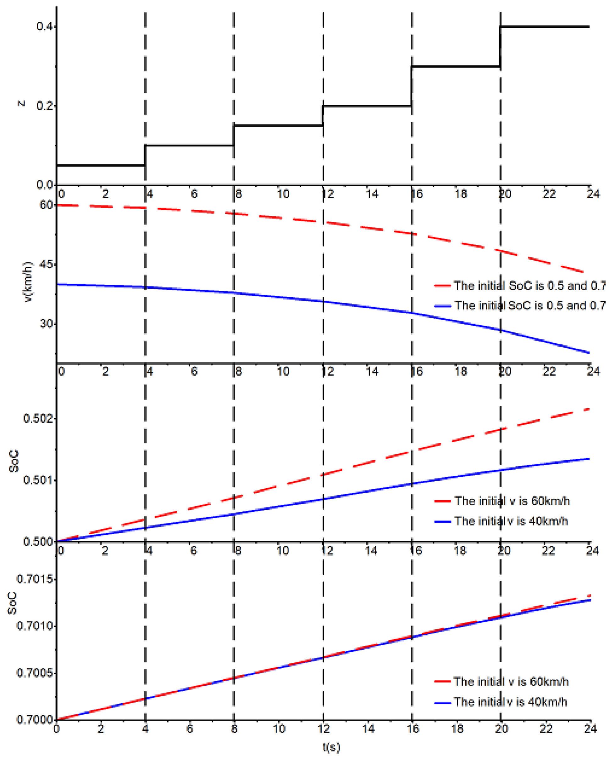
With the change of the braking severity, the trend of the vehicle velocity and the battery SoC are presented in Figure 3. As Figure 3 shows, during braking, the vehicle speed continuously decreases, and the battery SoC continuously increases. Compared with high initial SoC (SoCinitial = 0.7), at low initial SoC (SoCinitial = 0.5), the ability of recover electric energy is better, and the vehicle can recover more electric energy with higher initial braking speed. Furthermore, at high initial SoC, the initial braking speed has little effect on the regenerative braking energy recovery.
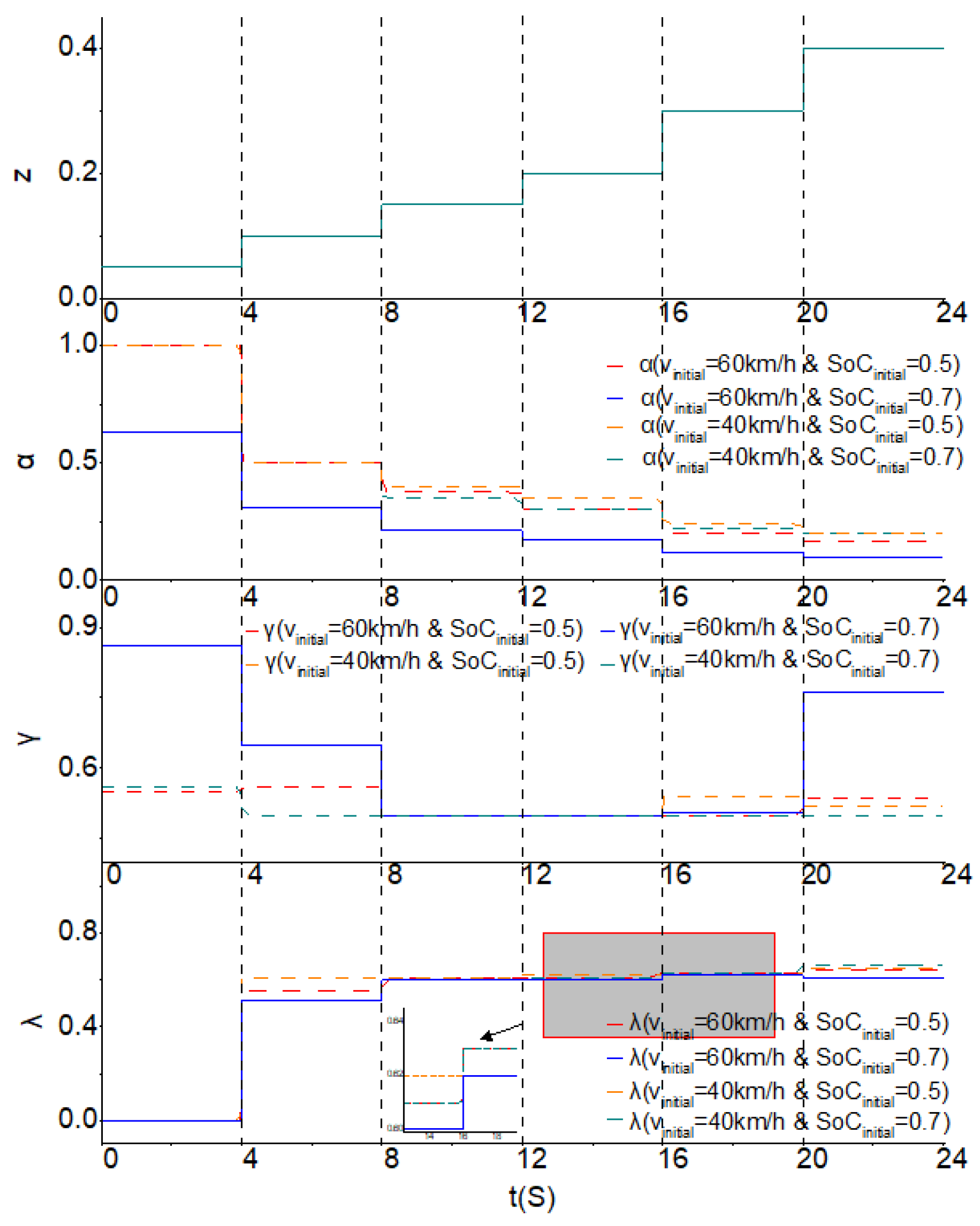
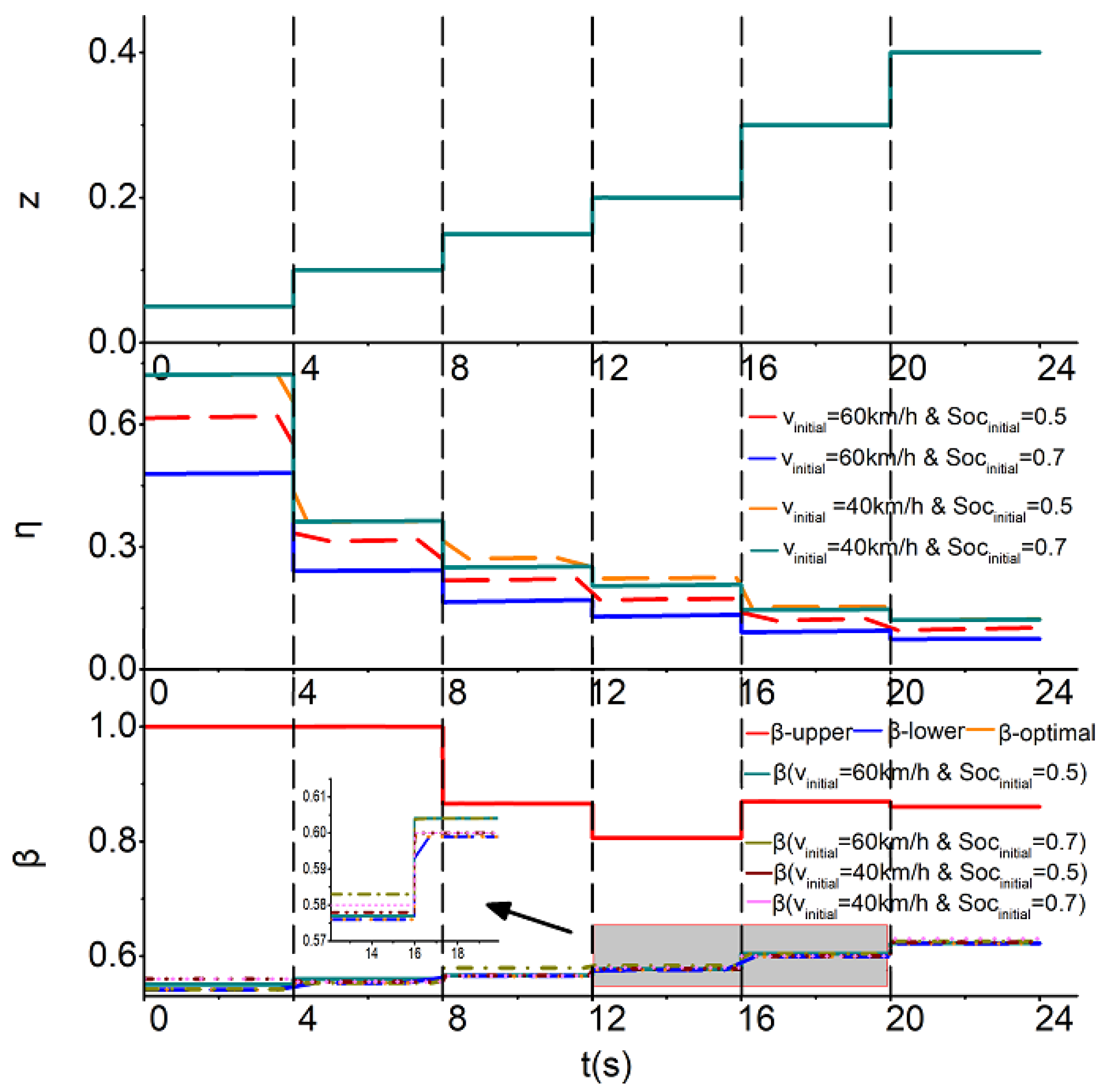
Figure 4 shows the trend of the optimization variables α , γ , and λ during braking. At high initial SoC and high initial braking speed (vinitial = 60 km/h), based on the characteristics of the in-wheel motor and the battery in the target vehicle, the proportion of the total regenerative braking torque in the overall braking torque is lower, and the proportion of the regenerative braking torque between the front axle and rear axles is higher. Moreover, under other conditions, these two proportions change only to a small extent. The vehicle speed and the SoC have little effect on the proportion of the friction braking torque between the front and rear axles.
Figure 5 presents the braking energy recovery efficiency and the braking torque distribution.
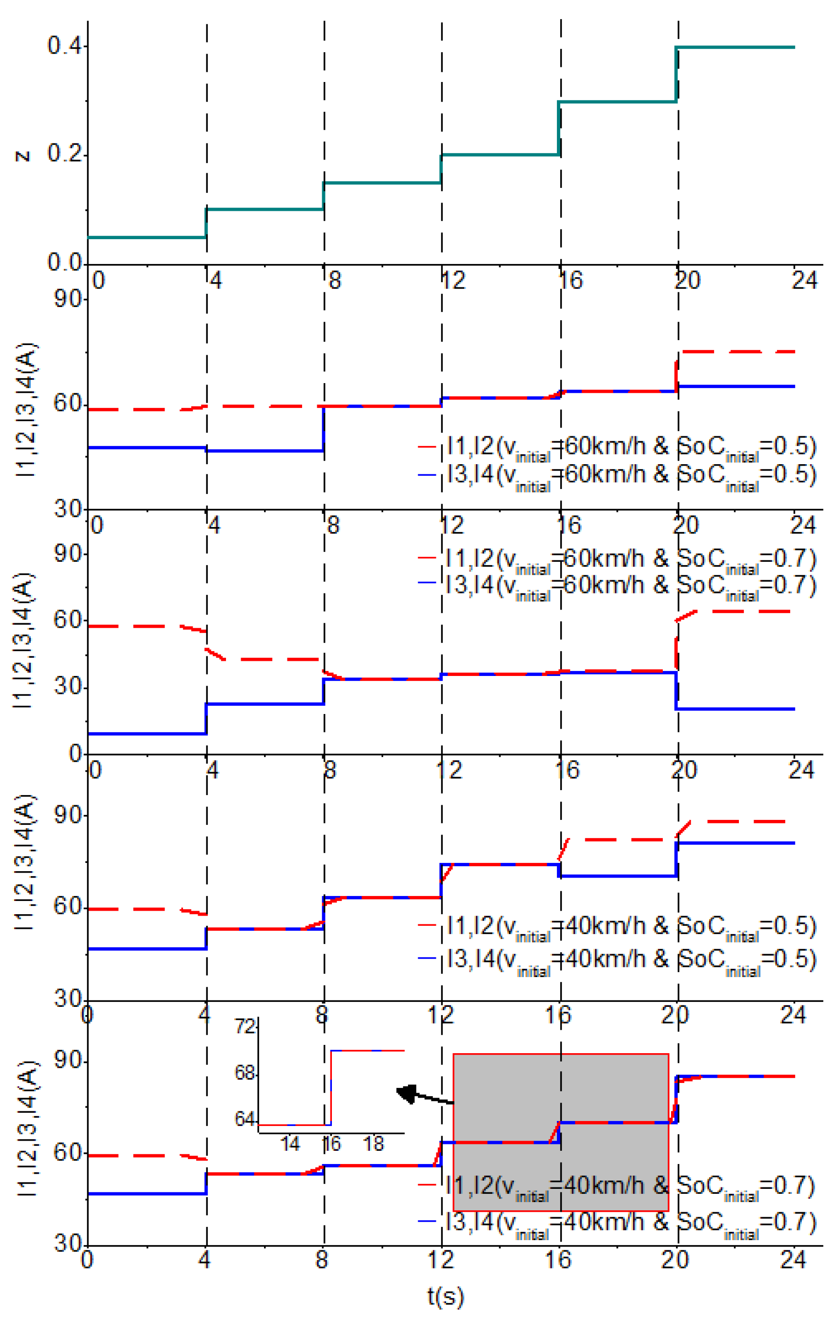
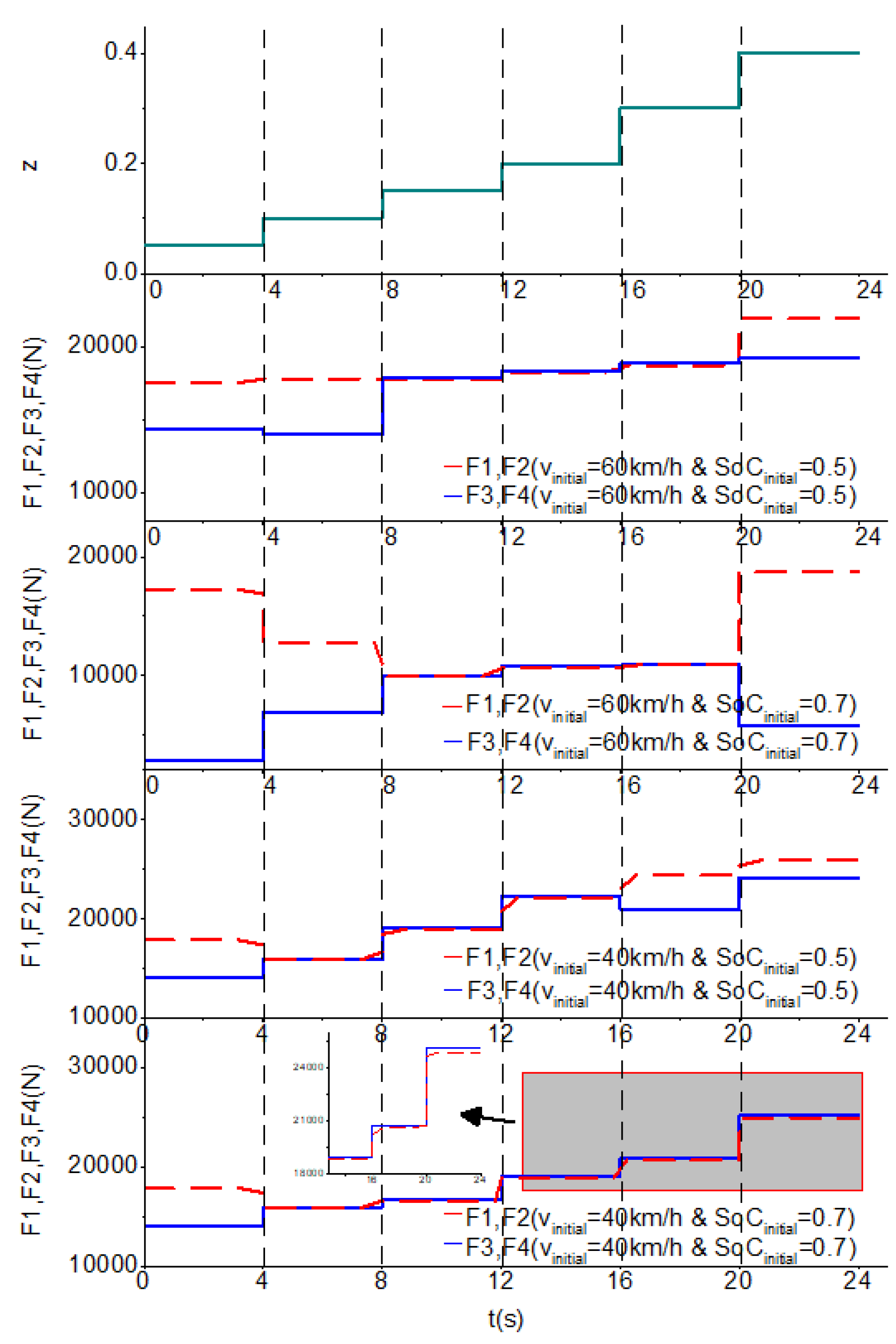
 Figure 6 and Figure 7 illustrate the control parameters I and F , respectively. As Figure 5 shows, the change in the vehicle speed has an impact on the regenerative braking energy recovery efficiency. Based on the characteristics of the in-wheel motor and the battery in the target vehicle, it has a regenerative braking energy recovery efficiency higher than 60 km/h, when the vehicle initial braking speed reached 40 km/h. At the low initial SoC, the vehicle has a higher regenerative braking energy recovery efficiency than the high initial SoC. In the entire braking process, the braking force distribution coefficient is close to the optimum value in the specified range, and the vehicle has good braking stability. Figure 6 and Figure 7 show that based on the novel regenerative–mechanical coupled brake-by-wire system, the regenerative braking current of the motor and the elastic force of the elastic element can be realized through optimization variables α , γ , and λ .
As Figure 3, Figure 4, Figure 5, Figure 6 and Figure 7 show, during braking, the vehicle speed continuously decreased, and the battery SoC continuously increased. Compared to the current braking systems, in the novel regenerative–mechanical coupled brake-by-wire system, a dynamic matching between the regenerative braking torque and friction braking torque is realized by controlling the electromagnetic torque of the motor and the elastic force of the elastic element to maintain a high braking energy recovery efficiency and a good braking stability. The entire braking system has a higher integration and a simpler structure.
The required braking torque can be entirely provided by the regenerative braking torque when the braking severity is low (z = 0.05). At the same time, friction braking is not part of the braking process, and the vehicle had a high braking energy recovery efficiency. With an increasing braking severity, the regenerative braking torque cannot provide the required braking torque, and friction braking starts to occur. At this time, determining the control parameters that can maintain a good comprehensive braking performance using conventional optimization methods is difficult. However, based on the collaborative optimization algorithm, the target vehicle has a high energy recovery efficiency and a braking force distribution coefficient close to the optimum value in the specified range. Ultimately, during the entire braking process, the deep learning algorithm was developed based on the collaborative optimization algorithm. The deep learning algorithm was obviously superior to the conventional methods.
The multiple correlation coefficient (R2) was used to evaluate the accuracy of the control parameters obtained using the deep learning control algorithm. The R2 values of α ^ , γ ^ , and λ ^ were 0.9889, 0.9817, and 0.9912, respectively.
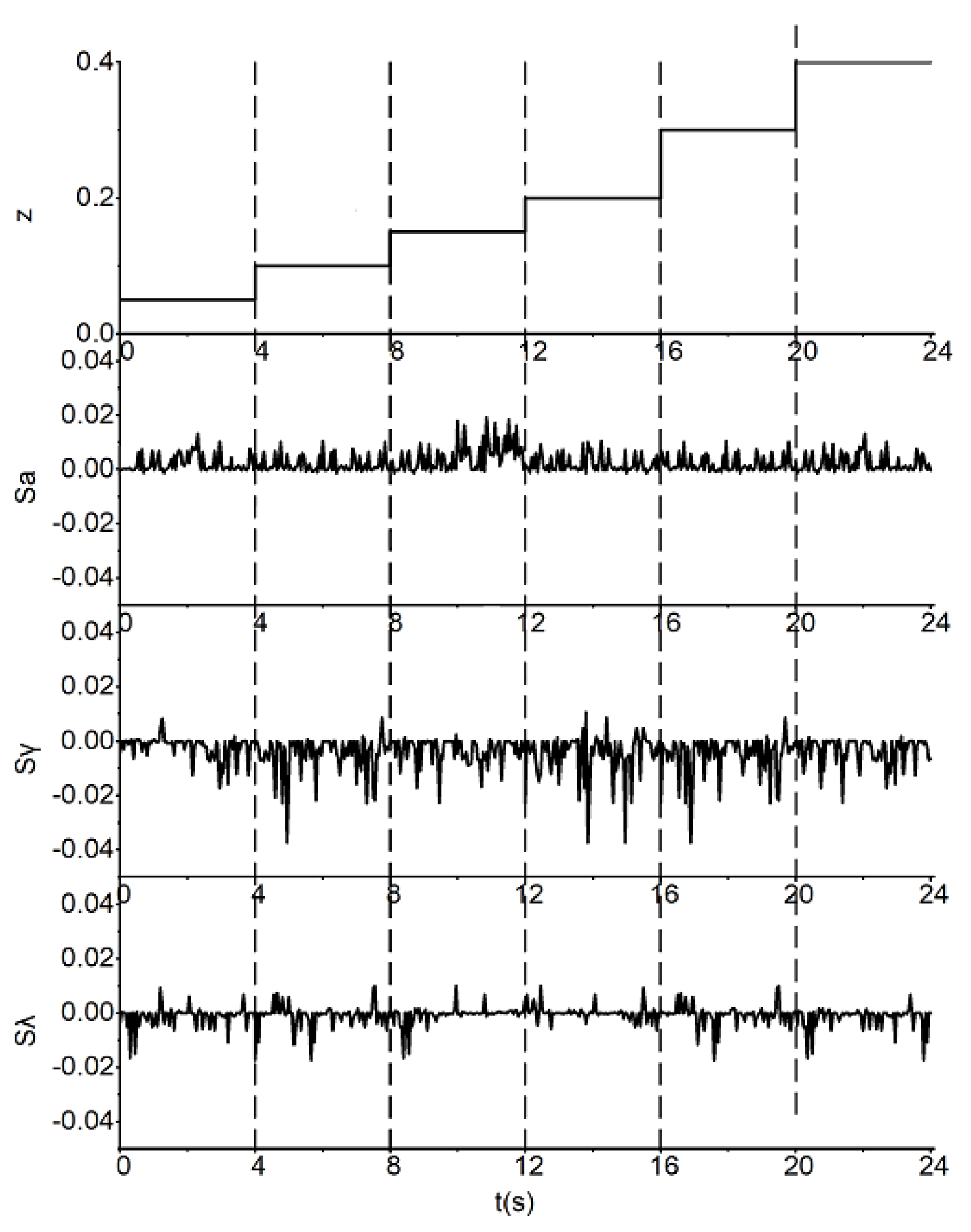
A relative error between the control parameters of the deep learning control algorithm and the online optimization values ( α 0 , γ 0 , λ 0 ) is defined to better evaluate the effectiveness of the deep learning control algorithm:
{ S α = | α 0 α ^ α 0 | 100 % S γ = | γ 0 γ ^ γ 0 | 100 % S λ = | λ 0 λ ^ λ 0 | 100 %
where S α , S γ , and S λ are the relative errors of α 0 , γ 0 , and λ 0 , respectively.
Figure 8 shows that compared to conventional methods [18,19], a smaller relative error can be found between the control parameters of the deep learning control algorithm and the online optimization values. The maximum value of the relative error was only 3.89%, which was within the expected error by 5%. The online optimization simulation required 43.7 h. However, the simulation based on the deep learning control algorithm required 6.9 s. The deep learning control algorithm can solve the poor real-time performance problem of the online optimization.
Hence, the deep learning control algorithm has a higher control precision than the conventional methods and a better real-time performance than the online optimization.

6. Conclusions

A deep learning control algorithm based on the novel regenerative–mechanical coupled brake-by-wire system was proposed herein. The main concluding remarks are as follows:
(1)
(A coupled braking mathematical model was built based on the novel regenerative–mechanical coupled brake-by-wire system. A braking torque distribution strategy involving regenerative braking and friction braking was also presented under a certain braking severity. Compared to the current braking systems, the novel regenerative–mechanical coupled brake-by-wire system had a higher integration and a simpler structure.
(2)
To achieve an optimal braking performance, an optimization model was established based on collaborative optimization theory. In this model, the comprehensive braking performance of the vehicle was treated as the object of the system level, and the braking stability and the regenerative energy recovery efficiency were treated as two disciplines. Optimal control parameters were then obtained based on the novel regenerative–mechanical coupled brake-by-wire system by coordinating the two objectives of the optimal braking stability and the optimal regenerative braking energy recovery efficiency.
(3)
By building a deep learning network, the deep learning control algorithm was developed using the in-depth characteristics of the sample points and the offline optimization results to obtain a higher control precision than the conventional methods.
(4)
The deep learning control algorithm can solve the problem of the poor real-time performance observed in online optimization. Hence, the deep learning control algorithm has a considerable application potential.
The results of this study demonstrated the characteristics of the novel regenerative–mechanical coupled brake-by-wire system and confirmed the feasibility of this system. This system offers an improved system integration and a simpler structure for use in EVs compared to the current braking systems. The deep learning control algorithm developed herein can serve as an important reference for manufacturers and researchers aiming to achieve optimal comprehensive braking performance in EVs with high control precision and good real-time performance.
The normal deceleration process was discussed herein. Considering emergency braking conditions, a deep learning control algorithm with a wider applicability will be studied in the future. Methods for reducing the error between the control parameters of the deep learning control algorithm and online optimization values will also be studied.

Author Contributions

C.H., G.W., and Z.G. conceived the control algorithm, performed the simulations, and finished the manuscript. Z.X. and D.X. revised the paper.

Funding

This research was funded by the National Natural Science Foundation of China under grant number 51175498.

Acknowledgments

The authors gratefully acknowledge the financial support from the National Natural Science Foundation of China (no. 51175498).

Conflicts of Interest

The authors declare no conflict of interest.

References

  1. Metz, L.D. Potential for passenger car energy recovery through the use of kinetic energy recovery systems (KERS). In Proceedings of the SAE 2013 World Congress & Exhibition, Detroit, MI, USA, 16–18 April 2013. [Google Scholar]
  2. Paganelli, G.; Ercole, G.; Brahma, A.; Guezzenec, Y.; Rizzoni, G. General supervisory control policy for the energy optimization of charge-sustaining hybrid electric vehicles. JSAE Rev. 2001, 22, 511–518. [Google Scholar] [CrossRef]
  3. Xiao, B.; Lu, H.; Wang, H.; Ruan, J.; Zhang, N. Enhanced regenerative braking strategies for electric vehicles: Dynamic performance and potential analysis. Energies 2017, 10, 1875. [Google Scholar] [CrossRef]
  4. Dincmen, E.; Güven, B.A.A. A control strategy for parallel hybrid electric vehicles based on extremum seeking. Veh. Syst. Dyn. 2012, 50, 199–227. [Google Scholar] [CrossRef]
  5. Li, L.; Zhang, Y.; Yang, C.; Yan, B.; Martinez, C.M. Model predictive control-based efficient energy recovery control strategy for regenerative braking system of hybrid electric bus. Energy Convers. Manag. 2016, 111, 299–314. [Google Scholar] [CrossRef]
  6. Cao, R.; Mi, C.; Cheng, M. Quantitative comparison of flux-switching permanent-magnet motors with interior permanent magnet motor for EV, HEV, and PHEV applications. IEEE Trans. Magn. 2012, 48, 2374–2384. [Google Scholar] [CrossRef]
  7. Vinot, E.; Trigui, R. Optimal energy management of HEVs with hybrid storage system. Energy Convers. Manag. 2013, 76, 437–452. [Google Scholar] [CrossRef]
  8. Zhang, J.; Chen, X.; Zhang, P. Integrated control of braking energy regeneration and pneumatic anti-lock braking. Proc. Inst. Mech. Eng. J. Automob. Eng. 2010, 224, 587–610. [Google Scholar] [CrossRef] [Green Version]
  9. Zhang, J.; Li, Y.; Lv, C.; Yuan, Y. New regenerative braking control strategy for rear-driven electrified minivans. Energy Convers. Manag. 2014, 82, 135–145. [Google Scholar]
  10. Kumar, C.S.N.; Subramanian, S.C. Cooperative control of regenerative braking and friction braking for a hybrid electric vehicle. Proc. Inst. Mech. Eng. J. Automob. Eng. 2016, 230, 103–116. [Google Scholar] [CrossRef]
  11. Jiweon, K.; Sungyeon, K.; Hanho, S.; Byoungsoo, Y.; Jaesueng, C.; Hyunsoo, K. Development of brake system and regenerative braking cooperative control algorithm for automatic-transmission-based hybrid electric vehicles. IEEE Trans. Veh. Technol. 2015, 64, 431–440. [Google Scholar]
  12. Kim, D.; Kim, J.; Wang, S.H.; Kim, H.S. Optimal brake torque distribution for a four-wheeldrive hybrid electric vehicle stability enhancement. Proc. Inst. Mech. Eng. J. Automob. Eng. 2007, 221, 1357–1366. [Google Scholar] [CrossRef]
  13. Zhang, J.; Song, B.; Cui, S.; Ren, D.B. Fuzzy logic approach to regenerative braking system. Intell. Hum. Mach. Syst. Cybern. 2009, 1, 451–454. [Google Scholar]
  14. Bera, T.K.; Bhattacharya, K.; Samantaray, A.K. Bond graph model-based evaluation of a sliding mode controller for a combined regenerative and antilock braking system. Proc. Inst. Mech. Eng. J. Automob. Eng. 2011, 225, 918–934. [Google Scholar] [CrossRef]
  15. Guo, J.G.; Jian, X.P.; Lin, G.Y. Performance evaluation of an anti-lock braking system for electric vehicle with a fuzzy sliding mode controller. Energies 2014, 7, 6459–6476. [Google Scholar] [CrossRef]
  16. Huang, X.; Wang, J. Model predictive regenerative braking control for lightweight electric vehicles with in-wheel motors. Proc. Inst. Mech. Eng. J. Automob. Eng. 2012, 226, 1220–1232. [Google Scholar] [CrossRef]
  17. Satzger, C.; Castro, R.D. Predictive brake control for electric vehicles. IEEE Trans. Veh. Technol. 2018, 67, 977–990. [Google Scholar] [CrossRef]
  18. Sun, F.C.; Liu, W.; He, H.W. An integrated control strategy for the composite braking system of an electric vehicle with independently driven axles. Veh. Syst. Dyn. 2016, 54, 1031–1052. [Google Scholar] [CrossRef]
  19. Guo, H.; He, H.; Sun, F. A combined cooperative braking model with a predictive control strategy in an electric vehicle. Energies 2013, 6, 6455–6475. [Google Scholar] [CrossRef]
  20. Wang, B.; Huang, X.; Wang, J.; Guo, X.; Zhu, X. A robust wheel slip ratio control design combining hydraulic and regenerative braking systems for in-wheel-motors-driven electric vehicles. J. Frankl. Inst. 2015, 352, 577–602. [Google Scholar] [CrossRef]
  21. Cheon, J.S. Brake by wire system configuration and functions using front EWB (Electric Wedge Brake) and rear EMB (Electric-Mechanical Brake) actuators. In Proceedings of the SAE 2010 Brake Colloquium and Engineering Display, Phoenix, AZ, USA, 10–13 October 2010. [Google Scholar]
  22. Jin, L.Q.; Sun, Z.X.; Zheng, Y. Coordinated anti-lock braking control of compound regenerative braking system in electric-wheel vehicle. J. Jilin Univ. 2017, 47, 1344–1351. (In Chinese) [Google Scholar]
  23. He, C.R.; Wang, G.Y.; Zhang, L.; Xing, Z.C.; Zhang, Z.F.; Gong, Z.P. A study on the mechanism of novel braking-by-wire system with regenerative-mechanical coupling for electric vehicles. Automot. Eng. 2018, 40, 283–289. (In Chinese) [Google Scholar]
  24. Khaled, I.; Alexandre, D.B.; Zoubir, K.; Ahmad, J. Comparison between two braking control methods integrating energy recovery for a two-wheel front driven electric vehicle. Energy Convers. Manag. 2016, 122, 330–343. [Google Scholar]
  25. Chu, L.; Liu, D.; Liu, H.; Cai, J.; Zhao, D. A study on the evaluation method of braking energy recovery in battery electric vehicle. Automot. Eng. 2017, 39, 471–479. (In Chinese) [Google Scholar]
  26. Guo, H. Optimization Study on Control Strategy for the Cooperative Braking System in an Electric Vehicle with Independently Driven Front and Rear Axles. Ph.D. Thesis, Beijing Institute of Technology, Beijing, China, 2014. (In Chinese). [Google Scholar]
  27. Park, J.S. Optimal Latin-hypercube designs for computer experiments. J. Stat. Plan. Inference 1994, 39, 95–111. [Google Scholar] [CrossRef]
  28. Ingber, L. Adaptive simulated annealing (ASA): Lessons learned. Control Cybern. 1996, 25, 33–54. [Google Scholar]
  29. Yann, L.C.; Yoshua, B.; Geoffrey, H. Deep learning. Nature 2015, 521, 436–444. [Google Scholar]
Figure 1. Novel regenerative–mechanical coupled brake-by-wire system.
Energies 11 02322 g001
Figure 2. Collaborative optimization algorithm.
Energies 11 02322 g002
Figure 3. Simulation results of v and SoC.
Energies 11 02322 g003
Figure 4. Simulation results of α , γ , and λ .
Energies 11 02322 g004
Figure 5. Simulation results of η and β .
Energies 11 02322 g005
Figure 6. Simulation results of I .
Energies 11 02322 g006
Figure 7. Simulation results of F .
Energies 11 02322 g007
Figure 8. Relative errors between the deep learning control algorithm and the online optimization simulations.
Energies 11 02322 g008
Table 1. Selected sample points.
Sampling PointsSoCv (km/h)z
10.325172.9860.0910
20.326383.9680.1270
30.637791.8240.2799
40.435799.2790.1419
50.296272.6650.1867
4970.334760.1600.1805
4980.273397.9160.0898
4990.774787.0940.2693
5000.303499.6790.2861
Table 2. Simulation parameters.
ParameterValueParameterValue
Kerb weight/(kg)885Coefficient of road adhesion0.85
Axis base/(m)2.347Initial speed of braking/(km/h)40, 60
Height of the mass center/(m)0.54Motor peak power/(KW)11
Front axle to mass center distance/(m)1.103Motor nominal speed/(r/min)1500
Rear axle to mass center distance/(m)1.244Number of motor4
Wheel effective radius/(m)0.304Initial battery SoC0.5, 0.7

