Adaptive Sliding Mode Speed Control for Wind Energy Experimental System


Division of Engineering, Saint Mary’s University, Halifax, NS B3H 3C3, Canada
Energies 2018, 11(9), 2238; https://doi.org/10.3390/en11092238
Submission received: 19 July 2018
/
Revised: 16 August 2018
/
Accepted: 23 August 2018
/
Published: 26 August 2018
(This article belongs to the Special Issue Power Electronics in Renewable Energy Systems)
Abstract
:In this paper, an adaptive sliding mode speed control algorithm with an integral-operation sliding surface is proposed for a variable speed wind energy experimental system. In the control design, an estimator is designed to compensate for the uncertainties and the unknown turbine torque. In addition, the bound of the sliding mode is investigated to deal with uncertainties. The stability of the system can be guaranteed in the sense of the Lyapunov stability theorem. The laboratory size DC generator wind energy system is controlled using a buck-boost DC-DC converter interface. The control system is validated by experimentation and results demonstrate the achievement of favorable speed tracking performance and robustness against parametric variations and external disturbances.
1. Introduction
Small-scale wind energy systems can be considered a solution to the low-to-medium energy demands for renewable sources. The efficient operations of such systems, in all wind speed regions, depends on the methods that regulate speed and power [1]. There are different configurations of wind turbine systems—fixed pitch, variable pitch and interfaced power electronics. Based on the wind system configuration, the speed and power can be regulated to optimize the operation [1,2,3].
In a below-rated wind speed region, the objective is to regulate turbine rotor speed and track desired optimum speed to extract maximum power from the wind, while minimizing the effects of uncertainties. In an above-rated wind speed region, the rotor speed can be controlled to follow a constant nominal speed, while the power is regulated to track the nominal value through the pitch angle controller. This control strategy is efficient compared to the use of only the pitch angle, as the generator torque cannot be assumed constant and requires to be controlled and maintained at its rated value [4,5].
Power electronics converters can be implemented to run the wind turbine in different wind regions (optimum below-rated wind speed and nominal above-rated wind speed) in power electronics interfaced wind energy systems [6,7,8]. The power electronics interface is regulated by a control system that maintains the desired levels of output voltages and currents, therefore controlling the torque and speed of wind turbines [9,10,11,12].
Sliding mode control (SMC) is used in the control field due to its good performance and simple structure. Furthermore, it handles uncertainties caused by un-modeled quantities, parametric variations, and modeling approximations [13,14]. The SMC control input includes a model control law based on model dynamics and a commutation control that attracts the state trajectory to the sliding surface. Various strategies for different generators in wind energy applications have been proposed. For doubly-feed induction machines, a second-order SMC is applied to optimize the power conversion [15,16]. A sliding mode control, combined with the field oriented control (FOC), is used for dual stator induction generator wind energy systems [17]. Furthermore, artificial intelligence (fuzzy, neural networks) based sliding mode control [18,19,20] and sliding mode control are used in DC machines [21]. In all these procedures, it is assumed that the turbine torque is known, by either measurement or calculation, which is not practically accurate as it randomly varies with change in wind speed. Furthermore, the compensation of unknown torque, unmodeled quantities and parametric variations is not guaranteed, as there is no adaptation mechanism to reduce their effects. In [22,23], SMC has been developed for power tracking with knowledge about wind turbine characteristics and aerodynamic torque observation. In [24], a second-order SMC, with fixed control gains, is applied to a DC generator based wind turbine experimental system.
The purpose of this paper is to design an SMC scheme that offers an adaptive mechanism to overcome the uncertainties found in traditional control systems. The proposed controller includes an estimator that deals with the unknown turbine torque and inaccuracies in the mathematical model of the system and attempts to achieve zero steady-state error. Furthermore, to overcome the problem of finding a suitable gain for the sliding mode control, a bound estimation algorithm is investigated, which reduces the chattering control effort and enhances the response of the overall control system through online adjustment. Investigation of the control strategy with the estimation is carried out using the Lyapunov theorem in order to guarantee closed loop system stability.
2. DC Generator Wind Turbine
The DC generator is modelled by the following equation:
where, i is the armature current, ω is the rotor speed, R is the resistance, L is the inductance, and Kb is back-emf constant.
The wind turbine is modelled by the mechanical dynamics of the rotor, such that:
where, ω is the rotor speed, Tt is the turbine torque to drive the rotor, Tem is the torque developed by the generator to oppose the driven torque, J is the total inertia (the rotor and the turbine), B is the friction coefficient, and includes uncertainties related to unmodeled quantities and external disturbances.
In this work, only rotor inertia is used in control implementation. The inaccuracy in total inertia can be seen as a disturbance to be compensated for by the control system.
The generator torque is given by:
where, Ki is the torque constant.
When operating the DC machine as a generator, the developed electric torque Tem opposes the mechanical torque developed by the wind turbine Tt. Therefore, by controlling the generator current i, the torque can be regulated, as shown in (3), to control rotor speed ω following the dynamics in (2).
The torque at the generator-turbine shaft, produced by the wind, is expressed as:
where, ρ is the air density, Ct is the torque coefficient, r is the radius of the turbine blade, vw is the wind speed.
In practical applications, the torque coefficient is unknown and the wind speed measurement is affected by noise. Therefore, the turbine torque can be considered as an unknown disturbance to be compensated for by the control system.
3. Sliding Mode Control for Speed Control
The SMC for speed control is developed using the dynamics of the rotor and the generator. Using Equations (2) and (3), rotational speed dynamics is expressed as:
where ω is the output, i is the control input, and is the disturbance input related to the turbine torque.
Considering uncertainties, such as unmodeled quantities, parametric variations and external disturbances, the dynamics (5) can be upgraded to:
where d is the disturbance input that includes all system uncertainties.
The control objective is to minimize the speed tracking error dynamics:
where e(t) = ω(t) − ωref(t) is the speed tracking error, ωref is the speed reference to be carried out using mechanisms for maximum or limited power extraction, and u(t) is a new control signal and expressed by:
Compensation of the uncertainties that are present in the system can be achieved by using SMC. In this work, a sliding surface, based on an integral operation, is used and expressed as:
where k is a positive gain.
Controlling the shaft speed can be achieved using the following speed control law:
where β is the switching gain and sgn(·) is the sigmoid function.
The term (k–Ap) is positive. Therefore, the choice of the gain k must satisfy the condition: k > Ap.
The choice of the gain β is based on the condition: always. It is assumed that system uncertainties are bounded magnitudes with known upper bounds.
The stability of the closed loop control system, defined using (6)–(10), is based on the Lyapunov theorem. A Lyapunov function candidate can be defined such as:
Using (7)–(10), the time derivative of the function (11) is expressed as:
The stability condition is satisfied based on (12). Therefore, the closed loop system is stable based on the Lyapunov theorem.
Finally, from (8) and (10), the control law, which is the current command i*, is given by:
The sliding mode control provides satisfactory tracking performance and robustness to system uncertainties. A drawback of conventional SMC is the appearance of chattering in the control input due to its discontinuity across the sliding surface. Chattering may excite high frequency dynamics, neglected during the system modeling. In this work, the chattering can be eliminated by smoothening the control discontinuity using the sigmoid function.
4. Adaptive Sliding Mode Control for Speed Control
4.1. Adaptation Based on Torque Estimation
The implementation of the control law (13) requires knowledge about the term f(t), which is related to the turbine torque Tt, as observed in (4). Practically, the turbine torque Tt is related to the exact knowledge of the torque coefficient Ct, which is not always available, and wind speed vw, which changes randomly and is affected by noise [1,2]. Therefore, the estimation of turbine torque in f can be a solution, as it takes into consideration the behavior of the closed loop system to improve the performance of the controller.
Using the torque estimation, the control law (13) becomes:
where is the estimation of f.
Torque estimation can be defined based on the following error dynamics:
where is the estimated error and η1 is a positive constant.
From (5) and (14), and considering slow dynamics of the turbine torque compared to the electric system, the estimation (15) is reorganized as:
The torque estimator can be expressed, by integrating (16), as:
The integral action of the speed tracking error allows the elimination of the disturbance in a steady state. Furthermore, the structure of the estimator (17), integrated with the control law (14), enhances the robustness of the controlled system with respect to uncertainties and disturbance rejection.
4.2. Adaptation Based on Bound Estimation
The dynamics of the control law (10) depends on the selection of the gain β, which can be conducted using trial and error to achieve good tracking performance. In this work, estimation is used for an automatic gain update to achieve high performance.
Replacing β by its estimated bound , the speed control law (10) becomes:
Estimated gain error of the bound value can be defined as:
The bound estimation law is based on the following Lyapunov candidate:
where, η2 is a positive constant.
On differentiating (20), with respect to time, and using (15) and (19), it is given that:
In order to achieve , the bound estimation law is designed as:
and (21) can be rewritten as:
In the adaptation law (23), there is no priori requirement to identify control gain. However, it can be observed from the -dynamics, that when S = 0. This condition shows that gain is over-estimated (the gain is always increasing), with respect to uncertainties, and induces larger chattering [23,24]. Furthermore, this methodology can be applied only for an ideal SMC, as the objective S = 0 cannot be reached in a real application. In this work, the information provided by the torque estimation (17), which includes uncertainties and perturbations, is used in the adaptation of the gain as follows:
where, and > 0, t* is the largest time value such that and ; (t*− is the time just before t*).
By supposing that , the adaptive gain control law (24) operates as follows:
- The gain increases to reach a value large enough to counteract the bounded uncertainty in (6), until the start of the SMC. The time for this start is t1.
- When the SMC starts, i.e., , from t = t1, is carried out using the adaptation (24) with . Using this mechanism, the gain can be decreased and adjusted depending on the actual uncertainties and disturbances.
- However, if the varying uncertainties move the sliding surface S(t) outside the interval ±ε, then gain adaptation will update in accordance with (24). The gain will increase until the sliding mode occurs again at the reaching time instant t2. As the sliding mode has occurred and from t = t2, now follows the gain adaptation law (24) with .
The process will continue operating as mentioned above depending on the condition of S(t).
The proposed SMC scheme with an adaptive mechanism is depicted in Figure 1. The control law i* is the control law carried out by the SMC speed controller. It will be used as the reference input for the current control loop to carry out control law V* and operate the generator side DC-DC converter.
5. Multivariable Control System of the DC Generator Wind Turbine
5.1. Maximum Power Point Tracking Control
If information on wind turbine characteristics is available, the speed reference ωref can be computed using optimum tip speed ratio λopt to maximize power extraction, such that:
The MPPT control algorithm can be implemented using (25), where wind speed measurements and wind turbine characteristics are required for accurate analysis. Due to measurement inaccuracies and lack of real models, this algorithm is not efficient in tracking the maximum available power. In this work, the MPPT control method, developed in [11], is used for maximum power extraction.
Using variation of the generated power P and the rotor speed ω, the speed reference profile, required in the closed loop control, is carried out by:
where, is gain. The generated power is carried out by measuring the generator voltage-current as:
In this MPPT algorithm, the choice of the ratio of the change in the generated power and the rotational speed will help improve speed tracking of both high and low wind speeds. Convergence can be achieved quickly by an adequate choice of the positive gain α.
5.2. Generator Current Control
The output of the speed control law (14) is the current reference used in the current control loop, developed from the electrical equation of DC generator (1), and is based on a proportional-integral (PI) regulator and the coupling term:
where, i* is the current reference, V* is the control law of the current control loop, and kp and ki are the proportional and integral gains, respectively.
The wind turbine-generator system is controlled by a cascade control structure; the SMC speed controller is the outer control loop and the current controller is the inner control loop, as shown in Figure 2. The output of the current controller is the firing signal of the MOSFET gate in the DC-DC buck converter.
5.3. Load Voltage Control
The control system on the load side is used to regulate load voltage, in order to be maintained at a level adequate to the LED’s specifications. The PI regulator based voltage control is expressed by:
where, VL is the load voltage, VL* is the voltage reference, U* is the control law of the load voltage control loop, and kp and ki are the proportional and integral gains, respectively.
The control output is the firing signal of the MOSFET gate in the DC-DC boost converter.
6. Wind Turbine Experimental Setup
The wind energy experimental system has a five-blade wind turbine from Quanser Inc. (Markham, ON, Canada), a DC generator, a power electronics interface, and an LED load bank. The speed and load voltage are controlled through the DC-DC converters of the power electronics interface, as shown in Figure 2. Details about the power electronics interface are available in [25].
Control testing under variable load is achieved using five controllable LED banks. Each bank consists of six parallel strings, with two LEDs in a series with resistance in each string, as shown in Figure 3.
The experimental wind energy setup is shown in Figure 4. The rotational speed is measured by an encoder. Voltage and current sensors are used for measurement at different points in the system (generator and load), as shown in Figure 4. These measurements are calibrated and received by the data acquisition board Q8-USB and the software package QUARC with MATLAB/Simulink.
A blower motor is used to generate wind speed and an incremental encoder, mounted on a blower rotor shaft, is used to measure its speed. The proposed control system does not require wind speed to control the wind energy system under maximum power extraction; this control model is a contribution of this work.
This wind turbine experimental setup has been used in other works to investigate different control strategies. In [3], a PI-based pitch control is used to regulate the rotational speed of the wind turbine. In [11], a feedback control strategy with an uncertainties compensator is developed to regulate the speed, whereas, in [12], a predictive control law is developed for the same purpose. In [24], a second-order SMC, based on a super-twisting sliding mode for perturbation and chattering elimination, is applied for speed control on the generator side. Its control gains are fixed and selected by trial and error to achieve good tracking performance. In this work, a different SMC strategy, based on an integral action, is proposed. It offers an adaptive mechanism to update the sliding control gain and an estimation mechanism to compensate the effects of the unknown wind turbine torque and system uncertainties.
7. Experimental Results
The characteristics of the laboratory scale wind energy experimental setup, used to verify the proposed control scheme, are given in Table 1 and Table 2. The overall control system is implemented using the MATLAB/Simulink software. The QUARC software is used to communicate to the hardware through the data acquisition board.
In the generator side control, the output signal of the speed controller is used as the reference for the current controller, where its output is transformed to a PWM signal and sent as an analog signal to the MOSFET gate. In the load side converter control, the output signal of the voltage controller is used to create the firing signal for the MOSFET gate of the second converter. The blower is controlled separately to generate a variable wind speed pattern, as shown in Figure 5.
Several experimental tests were conducted to verify the performance of the proposed control scheme to track variable step speed reference and maintain a fixed voltage across the load. The gains of all controllers are shown in Appendix A. The experimental system was run during a time interval of 160 s in order to allow good visualization of the system behavior during the transitions (step changes).
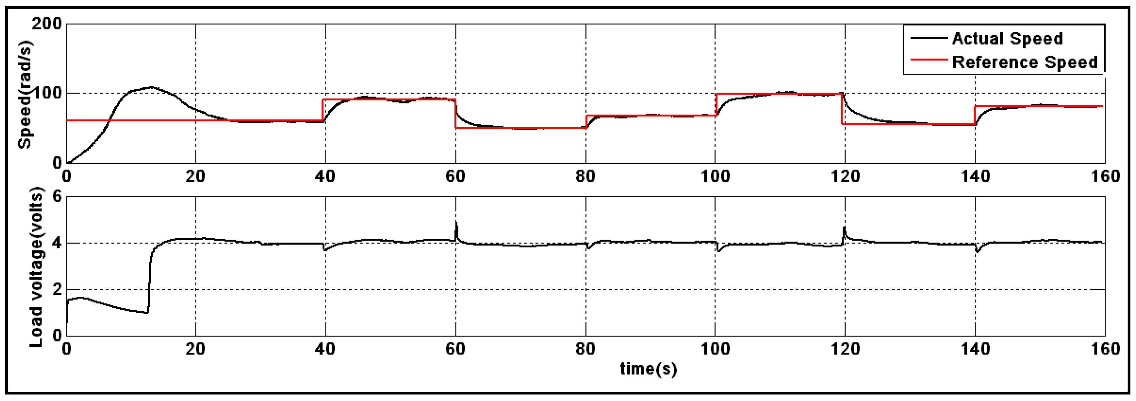
First, a traditional control system, based on PI regulators for speed, current, and voltage control, is carried out. Figure 6 shows that the performance of the speed controller is poor and its improvement depends on the parameter tuning of the three PI controllers. In the majority of cases, tuning is handled by trial and error, which is a time-consuming method as it is difficult to find optimal parameters. In addition, the PI controller is developed for a single input-output linear system, which is not the case in the wind turbine, as the electrical and mechanical equations are coupled. In Figure 7, a sliding mode speed controller, with a constant sliding gain β, is applied, where the same PI regulators as in the first experiment are used for the current and voltage controllers. Speed tracking is improved; however, voltage regulation is affected by the changes in the speed steps. Figure 8 shows speed tracking and voltage regulation using the adaptive SMC speed controller; it is observed that they are enhanced as the sliding gain is online adapted and the effect on the torque turbine is compensated by the estimation.
Friction quantity is considered unknown by the SMC and the tracking performance for speed and voltage is still good, as illustrated in Figure 9, highlighting the robustness of the control system.
In this experiment, the control system is tested under variable loads (as shown in Figure 10), where the switching state of each bank is changed during the operation. It can be observed, from Figure 11, that the performance of the proposed controller is still good and not affected by the load variation.
8. Conclusions
An adaptive sliding mode controller, based on torque and bound estimation, is presented to deal with speed tracking problems for a DC generator wind turbine experimental system. It is designed to compensate the unknown turbine torque, due to random variation in wind speed and system uncertainties due to parametric variations, unmodeled quantities and external disturbances. The SMC is enhanced by torque estimation to compensate the effect of the turbine, and adaptation of the control gain. The estimation is developed by the Lyapunov theorem to enhance the behavior of the overall control system. Finally, experimental results are presented to demonstrate the effectiveness of the proposed SMC scheme.
Funding
This research received no external funding.
Acknowledgments
The founding sponsors had no role in the design of the study; in the collection, analyses, or interpretation of data; in the writing of the manuscript, and in the decision to publish the results.
Conflicts of Interest
The author declares no conflict of interest.
Appendix A

Table A1.
Control gains.
| Control | Quantity | Value |
|---|---|---|
| Sliding mode | β (fixed) | 100 |
| η1, η2 | 10−4, 104 | |
| Speed PI | kp, ki | 3, 0.09 |
| Curent PI | kp, ki | 4, 0.2 |
| Voltage PI | kp, ki | 20, 0.5 |
References
- Barote, L.; Marinescu, C.; Cirstea, M.N. Control structure for single-phase stand-alone wind-based energy sources. IEEE Trans. Ind. Electron. 2013, 60, 764–772. [Google Scholar] [CrossRef]
- Yamamura, N.; Ishida, M.; Hori, T. A simple wind power generating system with permanent magnet type synchronous generator. In Proceedings of the IEEE 1999 International Conference Power Electronics Drive Systems, Hong Kong, China, 27–29 July 1999; pp. 49–854. [Google Scholar]
- Merabet, A.; Rajasekaran, V.; Kerr, J. Modelling and control of a pitch controlled wind turbine experiment workstation. In Proceedings of the 38th Annual Conference IEEE on Industrial Electronics Society (IECON), Montreal, QC, Canada, 25–28 Octorber 2012; pp. 4316–4320. [Google Scholar]
- Koutroulis, E.; Kalaitzakis, K. Design of a maximum power tracking system for wind energy conversion Applications. IEEE Trans. Ind. Electron. 2006, 53, 486–494. [Google Scholar] [CrossRef]
- Merabet, A.; Thongam, J.; Gu, J. Torque and pitch angle control for variable speed wind turbines in all operating regimes. In Proceedings of the 10th International Conference on Environment and Electrical Engineering, Roma, Italy, 1–7 May 2011; pp. 1–5. [Google Scholar]
- Kazmi, S.M.R.; Goto, H.; Guo, H.-J.; Ichinokura, O. A novel algorithm for fast and efficient speed-sensorless maximum power point tracking in wind energy conversion systems. IEEE Trans. Ind. Electron. 2011, 58, 29–36. [Google Scholar] [CrossRef]
- Arifujjaman, M.; Iqbal, M.T.; Quaicoe, J.E. Maximum power extraction from a small wind turbine emulator using a DC-DC converter controlled by a microcontroller. In Proceedings of the 4th International Conference of Electrical and Computer Engineering, Dhaka, Bangladesh, 19–21 December 2006; pp. 213–216. [Google Scholar]
- Lazarov, V.; Roye, D.; Spirov, D.; Zarkov, Z. New control strategy for variable speed wind turbine with DC-DC converters. In Proceedings of the 14th International Power Electronics and Motion Control Conference, Sofia, Bulgaria, 6–8 September 2010; pp. 120–124. [Google Scholar]
- Mayo-Maldonado, J.C.; Salas-Cabrera, R.; Cisneros-Villegas, H.; Castillo-Ibarra, R.; Roman-Flores, J.; Hernandez-Colin, M.A. Maximum power point tracking control for a DC-generator/multiplier-converter combination for wind energy applications. In Proceedings of the World Congress on Engineering and Computer Science, San Francisco, USA, 19–21 October 2011; pp. 1–6. [Google Scholar]
- Erickson, R.W. DC-DC power converters. In Wiley Encyclopedia of Electrical and Electronics Engineering; Webster, J.G., Ed.; John Wiley & Sons: Hoboken, NJ, USA, 2000. [Google Scholar]
- Merabet, A.; Islam, M.A.; Beguenane, R.; Trzynadlowski, A.M. Multivariable control algorithm for laboratory experiments in wind energy conversion. Renew. Energy 2015, 83, 162–170. [Google Scholar] [CrossRef]
- Merabet, A.; Islam, M.A.; Beguenane, R. Predictive speed controller for laboratory size wind turbine experiment system. In Proceedings of the Canadian Conference on Electrical and Computer Engineering, Toronto, ON, Canada, 4–7 May 2014; pp. 1–6. [Google Scholar]
- Barambones, O. Sliding mode control strategy for wind turbine power maximization. Energies 2012, 5, 2310–2330. [Google Scholar] [CrossRef]
- Evangelista, C.; Puleston, P.; Valenciaga, F. Wind turbine efficiency optimization. Comparative study of controllers based on second order sliding modes. Int. J. Hydrogen Energy 2010, 35, 5934–5939. [Google Scholar] [CrossRef]
- Kairous, D.; Wamkeue, R. DFIG-based fuzzy sliding-mode control of WECS with a flywheel energy storage. Electr. Power Syst. Res. 2012, 93, 16–23. [Google Scholar] [CrossRef]
- Evangelista, C.; Valenciaga, F.; Puleston, P. Multivariable 2-sliding mode control for a wind energy system based on a double fed induction generator. Int. J. Hydrogen Energy 2012, 37, 10070–10075. [Google Scholar] [CrossRef]
- Amimeur, H.; Aouzellag, D.; Abdessemed, R.; Ghedamsi, K. Sliding mode control of a dual-stator induction generator for wind energy conversion systems. Int. J. Electr. Power 2012, 42, 60–70. [Google Scholar] [CrossRef]
- Wai, R.-J.; Lin, C.-M.; Hsu, C.-F. Adaptive fuzzy sliding-mode control for electrical servo drive. Fuzzy Sets Syst. 2004, 143, 295–310. [Google Scholar] [CrossRef]
- Fallahi, M.; Azzadi, S. Fuzzy PID sliding mode controller design for the position control of a DC motor. In Proceedings of the International Conference on Education Technology and Computer, Singapore, 17–20 April 2009; pp. 73–77. [Google Scholar]
- Castaneda, C.E.; Loukianov, A.G.; Sanchez, E.N.; Castillo-Toledo, B. Discrete-time neural sliding-mode block control for a DC motor with controlled flux. IEEE Trans. Ind. Electron. 2012, 59, 1194–1207. [Google Scholar] [CrossRef]
- Rhif, A. Stabilizing sliding mode control design and application for a DC motor: Speed control. Int. J. Instrum. Control Syst. 2012, 2, 39–48. [Google Scholar] [CrossRef]
- Beltran, B.; Ahmed-Ali, T.; Benbouzid, M.E. Sliding mode power control of variable-speed wind energy conversion systems. IEEE Trans. Energy Convers. 2008, 23, 551–558. [Google Scholar] [CrossRef] [Green Version]
- Beltran, B.; Ahmed-Ali, T.; Benbouzid, M.E. High Order Sliding Mode Variable-Speed Wind Energy Turbines. IEEE Trans. Ind. Electron. 2009, 56, 3314–3321. [Google Scholar] [CrossRef] [Green Version]
- Merabet, A.; Islam, M.A.; Beguenane, R.; Ibrahim, H. Second-order sliding mode control for variable speed wind turbine experiment system. Renew. Energy Power Qual. J. 2014, 1, 478–482. [Google Scholar] [CrossRef]
- Merabet, A.; Kerr, J.; Rajasekaran, V.; Wight, D. Power electronics circuit for speed control of experimental wind turbine. In Proceedings of the 24th International Conference of Microelectronics, Algiers, Algeria, 17–20 December 2012; pp. 1–4. [Google Scholar]
Figure 1.
Adaptive sliding mode controller for the DC generator wind turbine.

Figure 2.
Schematic representation of the adaptive SMC system applied to the wind energy experimental setup.
Figure 2.
Schematic representation of the adaptive SMC system applied to the wind energy experimental setup.

Figure 3.
Electronic load.

Figure 4.
DC generator wind turbine experimental system.

Figure 5.
Wind speed profile.

Figure 6.
Speed tracking and load voltage under the PI control system.

Figure 7.
Speed tracking and load voltage under the SMC system.

Figure 8.
Speed tracking and load voltage under the adaptive SMC system.

Figure 9.
Speed tracking and load voltage under the adaptive SMC system with unmodeled quantity (friction).
Figure 9.
Speed tracking and load voltage under the adaptive SMC system with unmodeled quantity (friction).

Figure 10.
Variable load banks.

Figure 11.
Speed tracking and load voltage under the adaptive SMC system for variable loads.

Figure 12.
Speed tracking and load voltage under the adaptive SMC system and MPPT control.

Table 1.
Characteristics of the wind turbine.
| Quantity | Unit | Value |
|---|---|---|
| Blade radius (r) | cm | 14 |
| Blades number | - | 5 |
| Air density (ρ) | kg/m3 | 1.14 |
Table 2.
Characteristics of the DC generator.
| Quantity | Unit | Value |
|---|---|---|
| Resistance (R) | Ω | 2.47 |
| Inductance (L) | μH | 500 |
| Back-emf constant (Kb) | mV/rpm | 7.05 |
| Torque constant (Ki) | mNm/A | 67.3 |
| Viscous-friction (B) | - | 0.001833 |
| Rotor inertia (J) | g/cm2 | 110 |
© 2018 by the author. Licensee MDPI, Basel, Switzerland. This article is an open access article distributed under the terms and conditions of the Creative Commons Attribution (CC BY) license (http://creativecommons.org/licenses/by/4.0/).
Share and Cite
MDPI and ACS Style
Merabet, A. Adaptive Sliding Mode Speed Control for Wind Energy Experimental System. Energies 2018, 11, 2238. https://doi.org/10.3390/en11092238
AMA Style
Merabet A. Adaptive Sliding Mode Speed Control for Wind Energy Experimental System. Energies. 2018; 11(9):2238. https://doi.org/10.3390/en11092238
Chicago/Turabian StyleMerabet, Adel. 2018. "Adaptive Sliding Mode Speed Control for Wind Energy Experimental System" Energies 11, no. 9: 2238. https://doi.org/10.3390/en11092238
Note that from the first issue of 2016, this journal uses article numbers instead of page numbers. See further details here.