Decision Tree-Based Preventive Control Applications to Enhance Fault Ride Through Capability of Doubly-Fed Induction Generator in Power Systems


Institute of Technology, Graduate Program in Electrical Engineering, Federal University of Para, Belém-PA 66075-110, Brazil
*
Author to whom correspondence should be addressed.
Energies 2018, 11(7), 1760; https://doi.org/10.3390/en11071760
Submission received: 2 June 2018
/
Revised: 29 June 2018
/
Accepted: 2 July 2018
/
Published: 4 July 2018
(This article belongs to the Special Issue Intelligent Control in Energy Systems)
Abstract
:The development of a preventive control methodology to increase the capacity of voltage sag recovery (Fault Ride Through Capability (FRTC)) of a doubly-fed induction generator (DFIG) connected in an electrical network is presented. This methodology, which is based on the decision trees (DT) technique, assists with monitoring and support for security and preventive control, ensuring that wind systems remain connected to the power system even after the occurrence of disturbances in the electric system. Based on offline studies, DT discovers inherent attributes of the FRTC scenario related to electrical system behavior and provides a quick prediction model for real-time applications. From the obtained results, it is possible to check that the DFIG is contributing to a system’s operation security from the availability of power dispatch and participation in the voltage control. It is also noted that the use of DT, in addition to classifying the system’s operational state with good accuracy, also significantly facilitates the operator´s task, by directing him to monitor the most critical variables of the monitored operation state for a given system’s topological configuration.
1. Introduction
Doubly-fed induction generators (DFIGs) have excellent control and high energy efficiency when compared to fixed speed wind power systems, which makes them the best choice for many wind farm installations worldwide, if economic aspects are also taken into account [1]. Vector control techniques, especially those of oriented fields, allow decoupling of a machine’s active and reactive power control loops. Thus, DFIGs can independently control the active and reactive power, enabling the control of the machine’s terminal voltage or power factor.
However, when compared to variable speed synchronous generators wind systems, DFIG is easily affected by disturbances, because its stator windings are directly connected to the electric network. In the event of network failures, for example, short circuits, the DFIG terminal voltage may be very low in relation to its nominal value, and currents in the stator and rotor windings may be very high, representing a threat to operational security which can lead to the burning of the generator and converter components [2]. Formerly, the DFIG was disconnected from the electrical network and returned to normal operation only when the system had recovered from a fault occurrence. As the integration of wind systems into the electrical grid has increased, it has been established that wind systems must remain connected to the power system during disturbances, since the disconnection of large wind farms could cause stability problems. In this regard, different regulatory agencies in many countries have established technical requirements of survival during voltage sags (Fault Ride Through Capability (FRTC)), aimed at increasing the operational security [3].
The main existing methods to increase FRTC fall into two categories, namely, control improvement and hardware modification. Some proposed methods reduce the overcurrent during network failures or increase the DFIG transient stability margins, modifying the control of static converters, for example, through demagnetizing current control and double control techniques [4,5]. The methods of control improvement may present lower costs; however, the DFIG behavior is not satisfactory during voltage sags due to the limitations of converters [6].
Several hardware modifications have been proposed to reduce this problem. The conventional crowbar and chopper scheme is still widely used to reduce rotor overcurrent and DC link overvoltage in order to improve wind turbine operational security [7]. However, this scheme is not able to avoid electromagnetic torque oscillation which may damage the gearbox in extreme circumstances [8].
Other solutions have been adopted for the integration of large-scale wind farms, such as the use of static synchronous compensators (STATCOM) connected in parallel with the wind farm transmission line which can inject reactive power to assist with voltage control during electrical network failures [9]; dynamic voltage restorers (DVRs) connected in series with the transmission line may offset the terminal voltage by a transformer connected to the electrical network [10]. In addition to these alternatives, another cheaper solution is the use of a fault current limiter (FCL) as the series dynamic braking resistor [11] and the bridge type fault current limiter [12]. When using a power interruption circuit to perform commutations between normal operation and faults, the FCL can enlarge the transmission line’s equivalent impedance to reduce the overcurrent in both stators as rotor-sides during failures in the electric network.
In recent years, several hardware devices with new techniques have been proposed, such as the energy storage device and superconducting fault current limiter (SFCL). Combined control strategies are also used in these new devices, but they still have some limitations, as described in [13,14,15,16]. However, until now, no work has presented applications of preventive action based on the decision tree method for the increase in the DFIG Fault Ride Through capability. The use of automatic machine learning techniques provides a promising approach for defining the main control variables and their security limits in the DFIG operation, as will be presented in this article.
Traditionally, the data mining technique called decision tree (DT) has been widely applied in the area of energy systems for security evaluation and the application of preventive control [17,18,19]. The DT utilizes offline studies to discover intrinsic attributes of the electrical system. The knowledge obtained by DT can be directly used to aid the adoption of preventive actions in order to enlarge operational security in addition to providing a quick prediction model for real-time applications [20].
In addition, DT significantly reduces the set of options to be used in preventive control actions, allowing operators to remain more focused on the really critical security-related variables. Another significant aspect of DT is the fact that it presents a description of the critical variables that affect the system. This systemic characteristic is important because the set of critical variables for each network topological configuration can be distributed by various parts of the electrical system, often in places that would not be necessarily so apparent to the operator.
In addition to DFIG, other wind power technologies, such as the direct drive can also be adopted, as well as other forms of clean energy, such as photovoltaic generation and triboelectric nanogenerators. For this, it is important that these other forms of unconventional generation have good penetration in the electrical grid, because the larger their contributions to the generation of energy, the greater the contribution of their variables to preventive control based on the decision tree will be.
Thus, the main contribution of this work is the application of a preventive control method based on the decision tree method to enhance the DFIG FRTC. The innovative methodology has two methods of analysis: a local and a systemic one. The first chooses the attributes of the main control variables of the system and the second chooses only the DFIG controllable attributes which were selected by the DT during offline training as the attributes to be tuned during the preventive control process. The trained DT identifies the DFIG operational security limits for each topological configuration of the electrical system. The limits indicated are finally used as a guide to design preventive control strategies, thereby ensuring that the wind power system remains connected to the electrical network after a power system failure.
2. Methods and Materials
2.1. Doubly-Fed Inductcion Generator (DFIG)
DFIG is an induction generator that normally works in variable speed mode and is connected to the electrical network through static converters linked to the generator rotor. The most common configuration adopted by manufacturers is a schema with two static converters with Pulse-Width Modulation (PWM), connected to the rotor circuit and the power grid, respectively, as shown in Figure 1. This allows the generator to operate with shaft speeds above and below the synchronous speed, decoupling the system frequency from the generator rotation. DFIG is designed to make the most of the wind potential under different wind speeds and generator shaft rotation.
The Rotor Side Converter (RSC) controls, from the rotor injected power and current, the active and reactive powers circulating through the stator. The first models of doubly-fed induction generators adopted constant power factor control, usually unity, providing the maximum active power. With the increased penetration of wind systems, DFIG went on to provide reactive power under conditions of power system failures [21]. However, many power system operators offer a financial compensation to variable speed generators when supplying reactive power to the grid (ancillary service) [22,23].
The DFIG provides reactive power through both the stator and the Grid Side Converter (GSC). However, the GSC generally operates with a unit power factor, and does not provide reactive power to the electrical grid, controlling only the DC link voltage. To provide greater support to voltage control and to increase the reactive power capacity [24], the GSC converter must operate with a power factor that is different from unity.
The generator dynamic model adopted in this study was the software ANATEM (version10.4.6, The Electrical Energy Research Center (Cepel), Rio de Janeiro, Brazil) default model and the adopted model of turbine controllers was the ALSTOM ECO74 provided by ONS (Brasília, Brazil) [25,26,27].
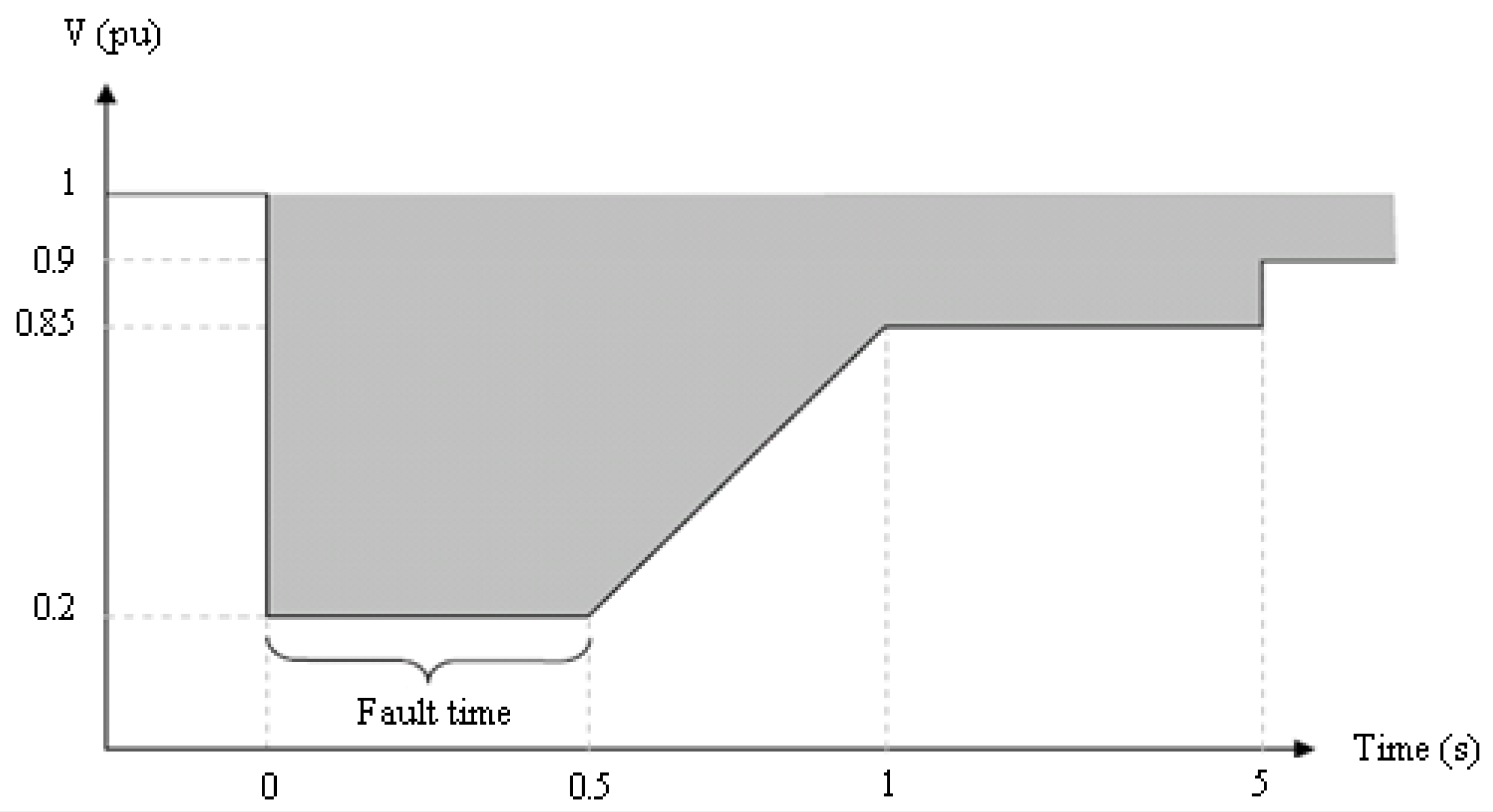
The FRTC technical requirement is defined as the ability of a generator to support network failures with resulting electrical voltage sags and remain connected after the occurrence of the disturbance [3]. For this, it is necessary that the generator terminal voltage remains above the defined FRTC curve and that the failure is eliminated during the time period defined by the same curve. In cases of voltage sags during one or more phases of wind generation at the connection point with the electrical network, the wind plant should continue operating if the voltage at its terminals remains above the curve shown in Figure 2; otherwise, the generator must be disconnected.
Figure 2 presents the terminal voltage tolerance limits of wind farms connected to the electrical network during the occurrence of power system disturbances.
2.2. Decision Tree (DT)
DT is a sorting algorithm belonging to the class of machine learning techniques that has the ability to learn through examples in order to sort records in a database. One of its most important features is the recursive partition of a dataset into several subsets until they contain only instances of a single class to allow better analysis of the problem. The DT so built presents results organized into a simple and easily interpretable form that can be used as a tool for decision making support.
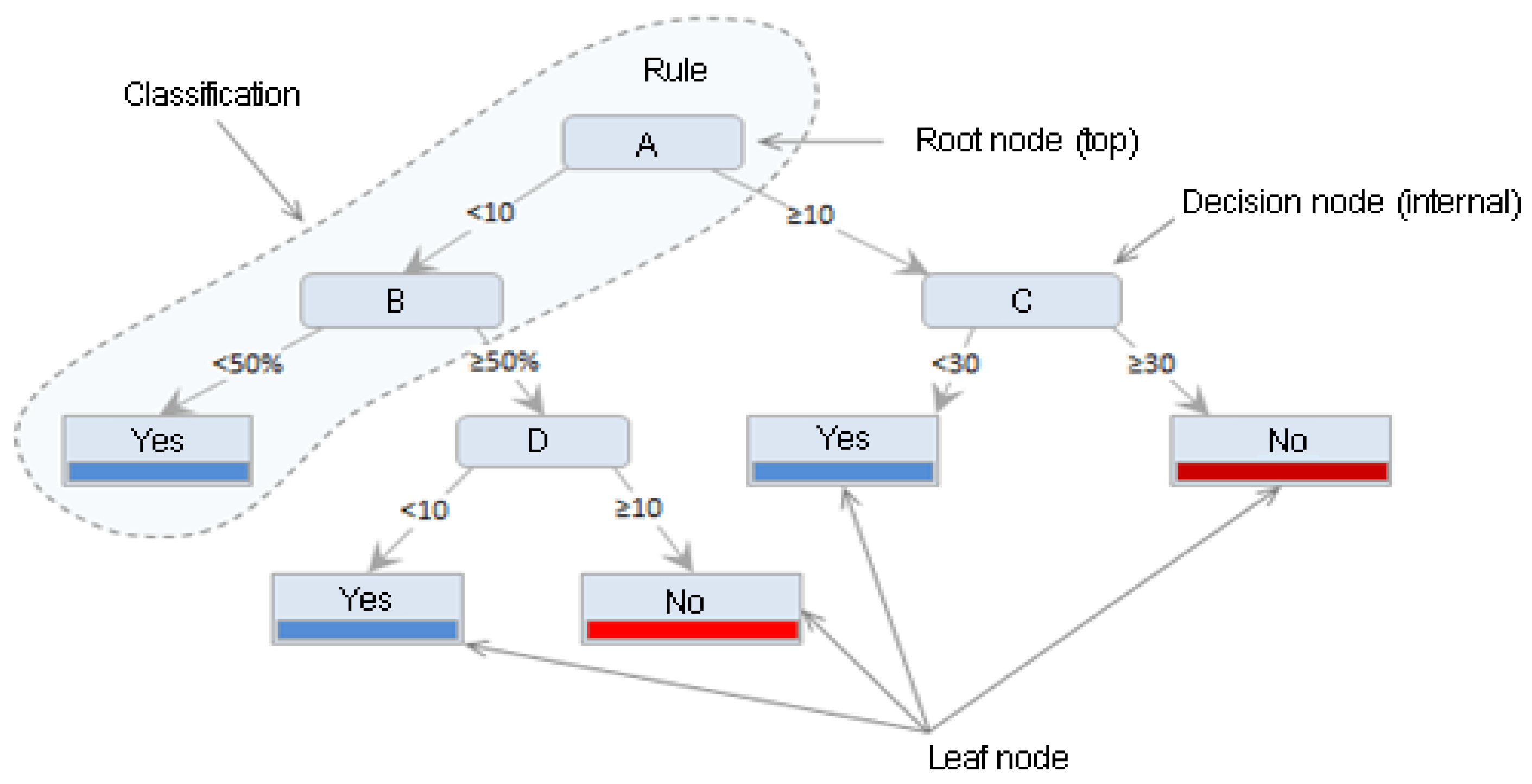
A DT is essentially a series of “if–then” statements, and its creation was based on the hierarchical model, that is, from the root node to the leave nodes. The nodes correspond to the attributes’ names, the nodes links represent the attributes’ values, and the leaves represent the different existing classes. The classification occurs following the path from the root node to the leaves where the classes are assigned, as highlighted in Figure 3.
The first decision tree-based classifiers arose in the late 50, from Hunt´s work, where several experiments were presented for the induction of rules. The “Classification and Regression Trees” (CART) algorithm was subsequently developed by Friedman, and Quinlan developed the “Iterative Dichotomiser 3” algorithm (ID3), and as a new development, after these two algorithms, came the C4.5 algorithm [28].
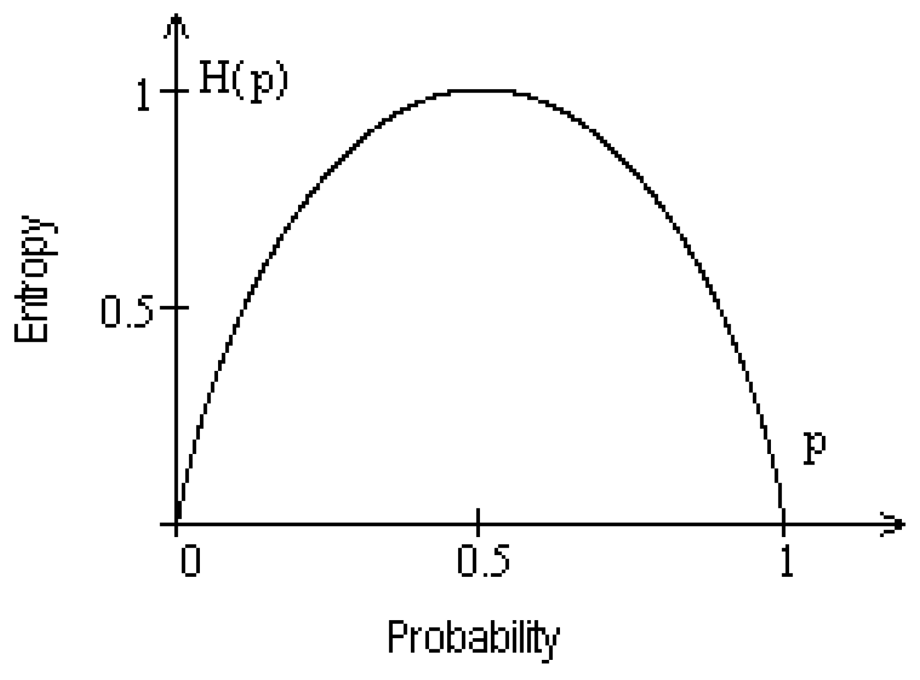
The C4.5 algorithm creates decision trees from a database in a similar way to the ID3 algorithm—by using the concept of entropy. Entropy is a measure of the degree of impurity in an arbitrary sample set, that is, it is the measure of disorder or randomness. Given a class A attribute of a sample set (S), in which A can take Vi values of different classes, the entropy of A concerning this classification is defined with Equation (1):
where m is the total number of classes and pi = p (A = Vi) is the probability of the class A attribute being equal to the class attribute whose index is (i), i.e., the ratio of the number of samples with a value of Vi in relation to the total number of samples of S.
The higher the entropy of an attribute, the more uniform the distribution of its values is. An entropy equal to zero means that one class in the data set has occurred, and it will be equal to 1 if the number of samples in each class are equal. An entropy near zero indicates that the classes are not uniform. Figure 4 represents the variation in entropy (H(p)) as a function of the probability (p).
During the process of creating a decision tree, the correct choice of attributes defines the success of the algorithm. Among the various criteria for choosing a candidate attribute to a node, the information gain is used. The information gain is based on entropy. The information gain is given by the sum of the individual entropies minus the joint entropy and is a measure of correlation between two variables.
Consider a sample set containing a class attribute (set as A) and one of the predictive attributes (set as B). The information gain (GI) of predictive attribute B is defined as the difference between the entropy of the class A attribute (Entropy(A)) and the conditional entropy of predictive attribute B, which is set as the value of the class A attribute (Entropy(B|A)). The information gain is given by Equation (2):
where the second term of Equation (2) is the conditional entropy, defined as the entropy of a predictive attribute, B, which was previously known the class A attribute. This is given by Equation (3):
where m is the total number of classes in the sample set, and B is the predictive attribute that is being considered. A is the class attribute, assuming value Vi. The term (Entropy (B|A = Vi)) is the entropy of predictive attribute B being given the value (A = Vi) of the class attribute.
where m is the number of classes that the class A attribute can assume, p(B|A = Vi) is the conditional probability of attribute B, that is, the proportion given by the ratio between the number of examples of B with A = Vi and the total number of samples in the class.
In the process of DT construction, the attribute that has the highest information gain should be placed as the root node to enable data to be sorted more quickly. The construction of the decision tree has three goals: to decrease the entropy, to be consistent with the data set, and to have the smallest number of nodes.
3. Methodology
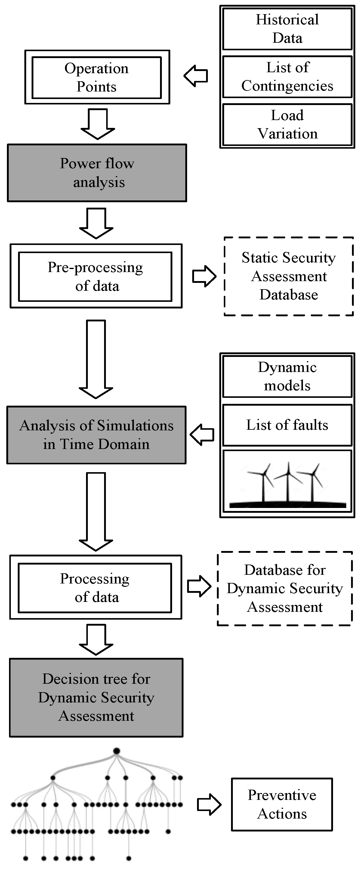
The methodology of preventive control developed in this article can be applied in real-time operation and in very short-term planning studies focusing on the operational security assessment of wind systems integrated into the electrical grid. The methodology also enables the accomplishment of a preventive assessment of the future operating state with topological changes such as unplanned outages of transmission lines and generating units and the switching of capacitor banks and reactors among other contingencies. This feature allows operators to analyze preventive actions to be taken if these contingencies happen in future operations. Figure 5 shows the flowchart of offline procedures used to establish the database.
It is important to note that the proposed procedure involves an offline step and another step in real time. The database creation is performed offline, as the integration step of the methodology with the Supervisory Control and Data Acquisition/Energy Management System (SCADA/EMS). The database is formed from the information of each operation point provided by the state estimator for each topological configuration determined by the network configurator.
From the operation data, planning data, and load variations around each operation point, several cases are created for decision tree training.
From historical data and a list of the most critical contingencies or those with greater probability of occurrence, new operating scenarios are generated in order to simulate the load variation that may occur during a normal operation day. Using the computer program ANAREDE [25], which is adopted for power system steady state studies, load flow simulations are performed to obtain the initial conditions for each operation point of the system.
At this step, using the power flow study solutions, the database for static security assessment is created. The static database is required to obtain data to allow the initial conditions of the operation point to be analyzed by the dynamic simulation studies. Now, using the computational tool ANATEM [26], adopted for the analysis of electromechanical transients in electrical systems, time domain simulations are performed with dynamic models (synchronous generators, wind generators, and associated controls), forming a dynamic database to create decision trees to be used for dynamic security assessment.
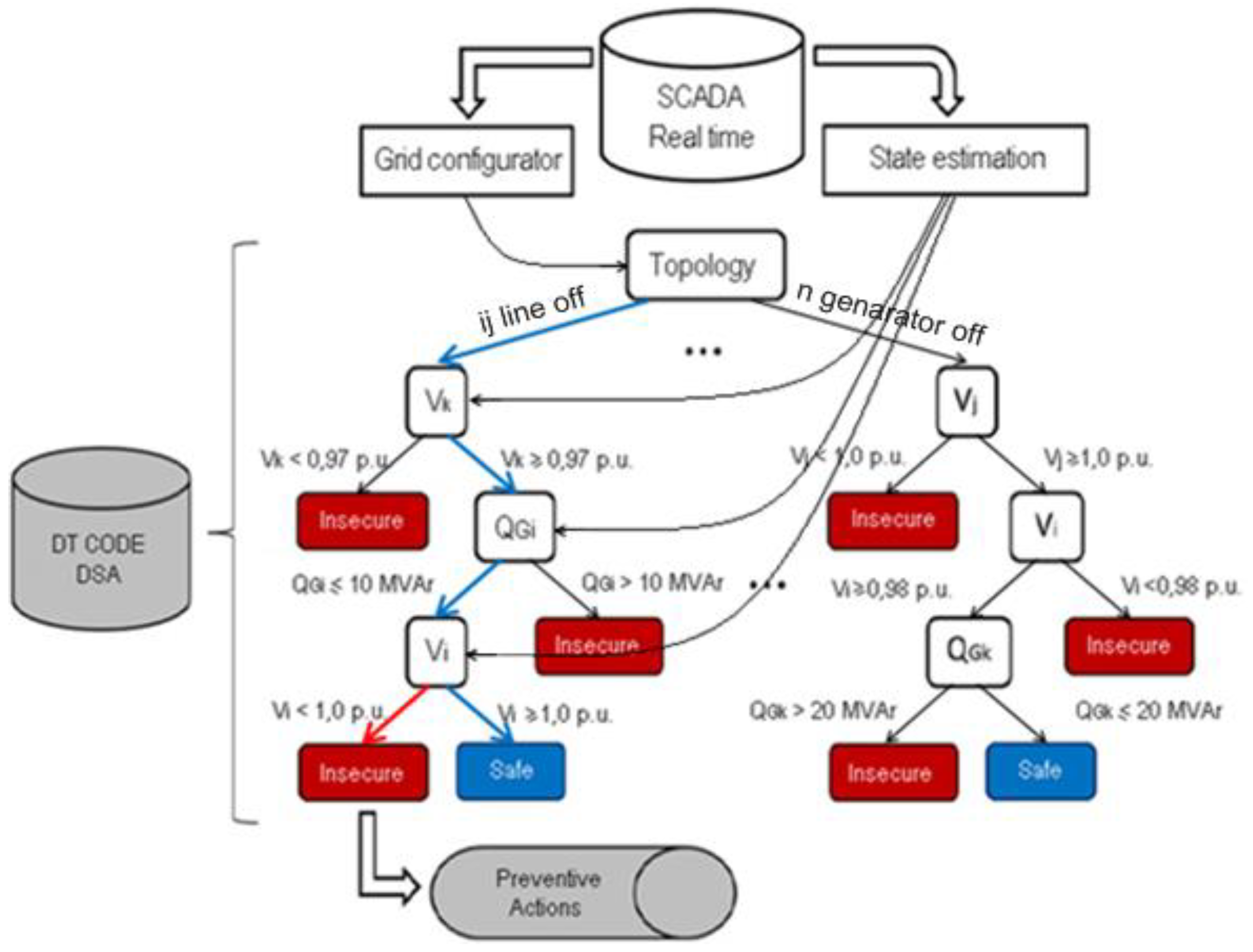
Finally, using the data mining software Rapidminer [29], decision trees are constructed to assist with preventive control. The created decision trees evaluate dynamic security in real time, highlighting only those variables that have the largest influence on every topological configuration of the electrical system, thereby generating a smaller set of variables that deserve the attention of operators at the power system operation point. Each DT branch carries a rule that, when met, guarantees the security of the wind generator operation after network failure. Figure 6 shows this real-time operation scenario schematically.
After classifying the system’s operational status, preventive actions can be performed if the system presents any operation limit violation, as indicated by the decision tree.
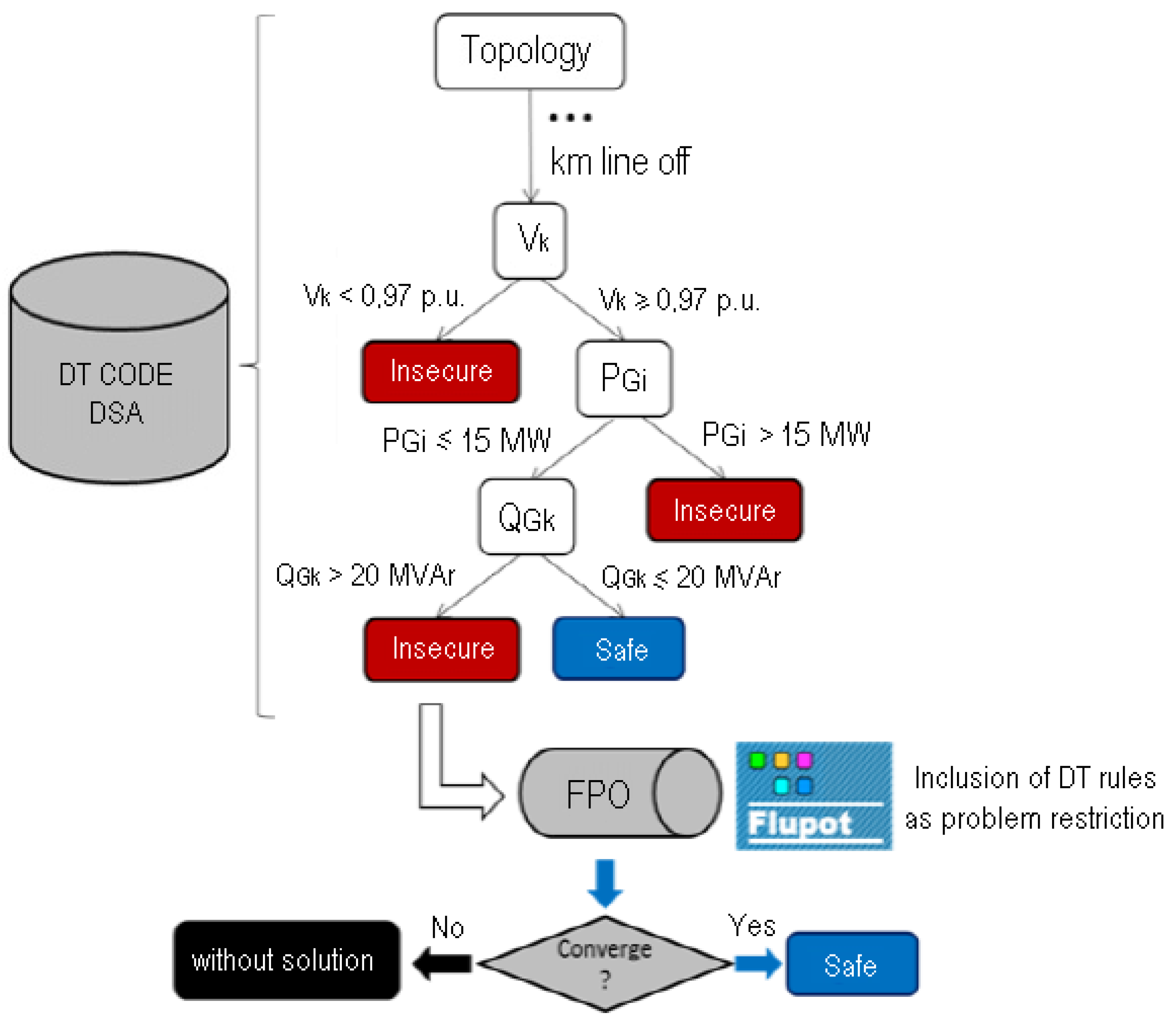
Preventive control actions can be taken to prevent the occurrence of serious consequences to the electrical system. In this case, the decision variables presented by the DT indicate the path to maintain DFIG dynamic security within each power system topology. FLUPOT software (version9.7.2, The Electrical Energy Research Center (Cepel), Rio de Janeiro, Brazil) [25], a computer program for power system optimization, is used to obtain optimal solutions for power system operation using the voltage security constraints indicated by the DT solution. Figure 7 shows the operation scheme involving preventive control actions.
The methodology developed in this article may be applied to local and systemic scenarios, as illustrated in Figure 8. In systemic scenarios, electrical variables related to the electrical system as a whole are chosen as attributes, while in local scenarios, only the DFIG controllable attributes are chosen to participate in the preventive actions to be implemented by the DT.
To create the decision tree in systemic case studies of preventive control applications with a focus on DFIG FRTC, a large database must be created with a large number of objects. Each row represents a static pre-contingency condition of the power system, (every object is an attribute of a power flow solution with control variables available in the whole system), along with the results (disconnection and Fault Ride Through) of a dynamic simulation in the time domain. Table 1 presents the systemic database structure.
With respect to the decision tree creation applied to the local case study, each row represents a static pre-contingency condition of the power system (every object is an attribute of a power flow solution with control variables of the local wind system), along with the results (Disconnection and Fault Ride Through) of a dynamic simulation in the time domain. Table 2 presents the systemic database structure.
4. Results
For the purpose of testing and validating the proposed methodology for preventive control based on decision trees, case studies were carried out using the IEEE New England-39 bus test system. The results will be presented in the following text.
The New England test system is originally formed by 39 buses having 10 synchronous generators. Generator 1 is an equivalent model representing part of the electrical network over which there is no control, and generators 2 to 10 are controlled by automatic voltage regulators. Figure 9 illustrates the single-line diagram for the modified test system, considering the integration of variable speed wind generators at buses 40, 41, 42, 43, 44, and 45.
The IEEE test system was modified by considering the integration of wind farms representing 30% of the total power generated by the system. Six new buses were inserted with wind farms. Each wind generating unit was given a nominal power of 1670 kW. Table 3 presents a summary of the wind generation given by the test system, detailing the installation bus number, the number of turbines installed, and the resulting maximum power generation.
4.1. Case Study of the Preventive Control Application Focusing on the DFIG FRTC—Training and Testing the Systemic Analysis Method
Firstly, the modified IEEE-39 bus test system was considered for simulation. From a defined base case, new scenarios were generated for different load variation conditions. Another four (N-1) type topological conditions representing line and generator outages were added to the database and were complemented with new operating scenarios. Then, these files were simulated using the power system analysis software ANAREDE to obtain the initial conditions of the bus voltages, transmission lines power flows, set points for control variables, and generation of active and reactive power values, forming the simulation database. For each topology, 200 simulations were carried out, representing a total of 1000 scenarios.
Later, with the purpose of carrying out time domain simulations, files of the initial conditions, representing the electric network, were added, comprising dynamic data describing synchronous generators, wind turbines, and associated controls to accomplish simulation studies to generate preventive control actions against disturbances that cause wind generators to be disconnected due to voltage sags. The critical event for testing was the application of a short circuit of 100 ms in transmission line LT 28–29. The dynamic simulations were carried out using the time domain dynamic analysis software ANATEM.
The database for dynamic security assessment was then generated with a symbolic attribute (the topological signature) and the numeric attributes, Vi (voltage magnitude), θi (phase angle), Pgi (generated active power), and Qgi (generated reactive power), which constitute the pre-fault conditions, as well as two target attributes, “Fault Ride Through” (if the voltage magnitude does not exceed the established limits) and “Disconnection” (if the voltage exceeds the predefined limits).
Finally, the data miner software Rapidminer was used for the creation of an intelligent system based on the decision tree method to assess the preventive control and dynamic security using, as a pattern, 70% of the data for training and 30% for testing. Figure 10 shows the decision tree model generated with topological orientation for dynamic security assessment and preventive control aid purposes, in order to ensure that the wind turbines will survive the voltage sags.
Table 4 presents the confusion matrix corresponding to the created decision tree to evaluate the efficiency of the implemented model by determining whether the predicted value matches the final value.
It can be observed in the presented results, that the hit rate (accuracy) was 98.67%, and only one case predicted “Disconnection”, when, in reality, it was “Fault Ride Through”. The prediction of the “Disconnection” class reached a precision rate of 99.31%, while the prediction of “Fault Ride Through” class was accurate to 98.08%. Both classes presented good performances.
The selected attributes provided to Rapidminer were voltage magnitudes in all generation buses, active and reactive power values for PV buses, network topology, and the labels “Fault Ride Through” and “Disconnection”. As can be seen in Figure 10, the decision tree root node is the system topological configuration.
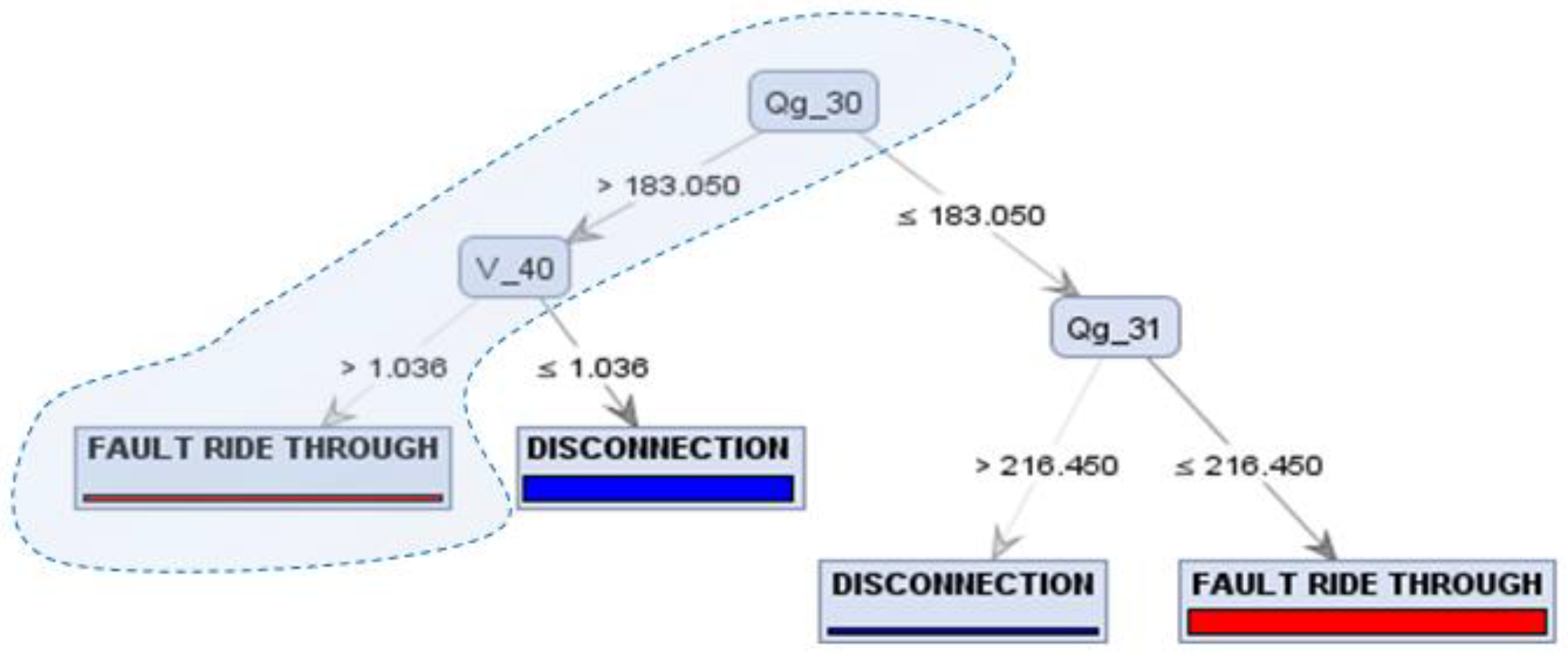
When analyzing the model in Figure 11 provided by the decision tree, the first branch on the left represents the path that will ensure electrical power system security for the complete topology. The operator, observing the current system topology, needs only to follow the variables and guidelines established by the decision tree to ensure the wind farm will survive the voltage sag.
It can be observed in Figure 11 that the decision tree rules circuled by the dotted line, if adopted, can ensure the wind turbines survive voltage sags under this current topology.
The rules found by the DT algorithm that have greater influence with regard to power system security are, in hierarchical order, as follows: If Qg_30 > 183.05 MVAr and V_40 > 1.036 pu, then the wind farm will remain connected, as noted in the presented results. The first variable of the first branch of the decision tree is the reactive power generated at bus 30 and the second variable is the wind turbine voltage magnitude at bus 40. The rules of this branch can be directly used to take preventive actions locally or remotely.
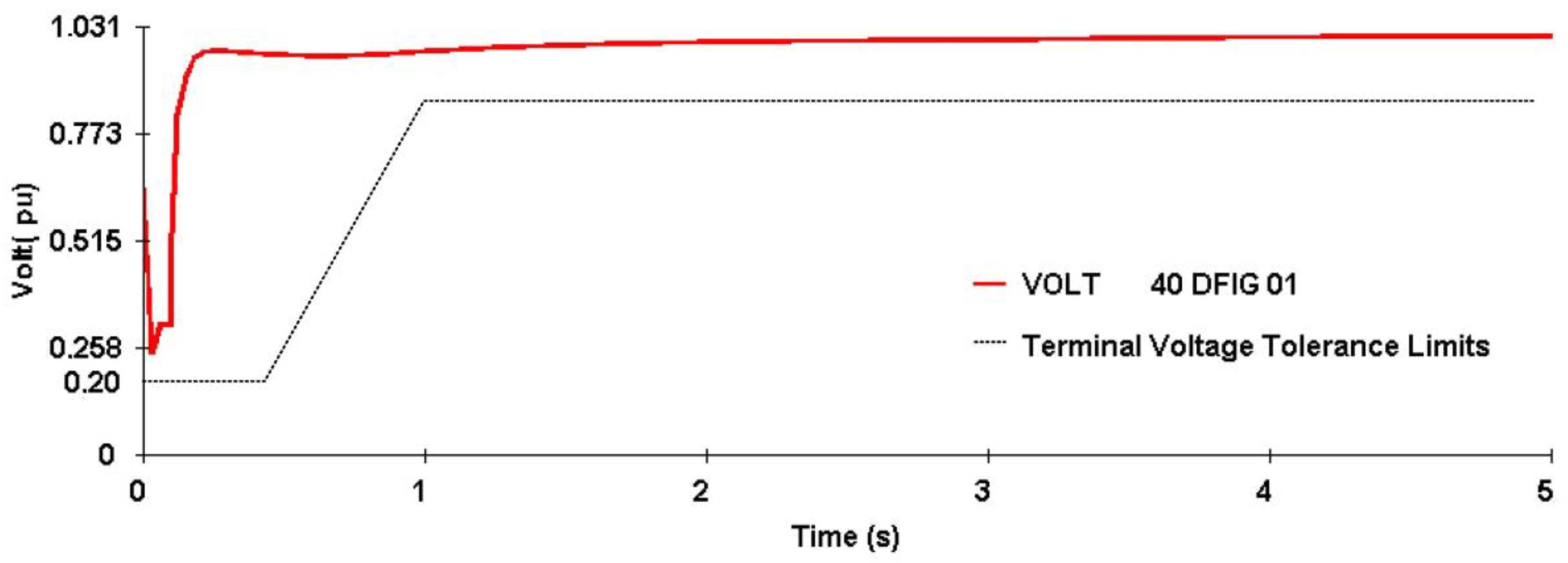
Figure 12 presents the dynamic behavior of the electrical system during wind generation when a short circuit lasting 100ms is applied in line LT 28–29. The result shows that due to this disturbance, the DFIG terminal voltage at bus 40 violates the limit of the voltage curve established by the standard which may lead to protection action, thereby disconnecting the wind farm.
In order to prevent the wind turbine being disconnected due to voltage sags, a case where voltage sag occurred at bus 40, with Qg_30 = 184.7 MVAr and V_40 = 1.020 pu was considered, and it appeared that part of the decision tree rules was not met as soon as the wind turbine voltage was below the limits set by the standard. Therefore, in this case, the wind farm would be disconnected.
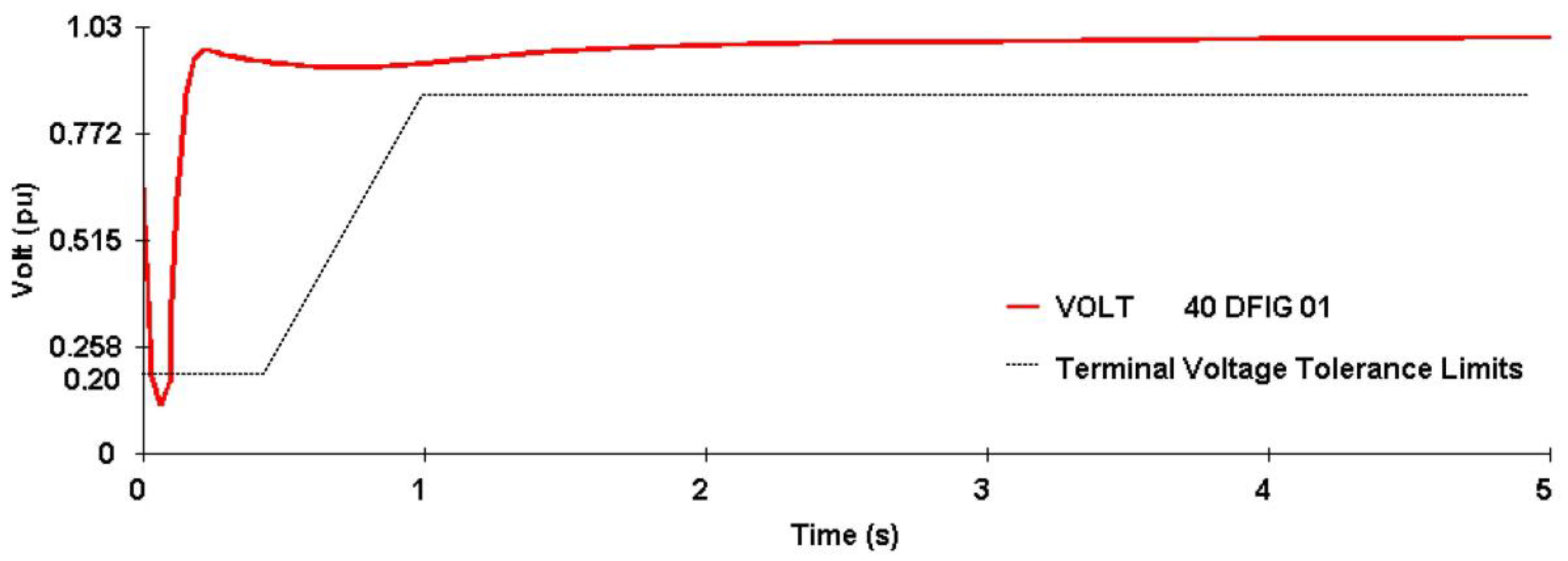
So, as a solution, the optimization software FLUPOT was run, adopting an objective function involving voltage control and the decision tree rules. Thus, the voltage magnitude of bus 40 was changed from V_40 = 1.020 pu to V_40 = 1.041 pu, and the reactive power Qg_30 of 184.7 MVAr was changed to 184 MVAr. The obtained results are shown in Figure 13.
It can be observed in Figure 13 that the optimized adjustment considering the DT rules increased the wind turbine’s survival following voltage sags at bus 40. From the obtained results, it is possible to verify that variable speed wind systems can also contribute to increase dynamic security through the availability of their control variables.
To ensure the electrical system’s operation security, the operator observing the system topology under operation, needs to take into account the variables and rules established by the decision tree, taking preventive actions accordingly to ensure the continuity of the wind farm’s operation after disturbances in the electrical system.
4.2. Case Study of the Preventive Control Application Focusing on the DFIG FRTC—Training and Testing of the Local Analysis
The preparation of the database for local analysis was similar the method used in the systemic study, as presented in Section 4.1, where the file corresponding to the IEEE 39-bus test system which was modified to include wind turbines generation representing 30% of the total electrical system generated power was used. Figure 14 shows the decision tree model generated with topological orientation for dynamic security assessment and preventive control aid purposes.
Table 5 presents the confusion matrix corresponding to the created decision tree to evaluate the efficiency of the implemented model. It can be observed that the hit rate was 100%, with 100% also being the precision in predicting the “Disconnection” class.
The prediction of the “Fault Ride Through” class also reached an accuracy of 100%. Both classes presented excellent performances.
The selected attributes provided to Rapidminer were voltage magnitudes, active and reactive generated power by the wind farm at bus 40, network topology, and the labels “Fault Ride Through” and “Disconnection”. As can be seen in Figure 14, the decision tree root node was the system topological configuration.
When analyzing the model in Figure 15 provided by the decision tree, the first branch on the right represents the path that will ensure electrical power system security for the complete topology. The operator, observing the current system topology, needs only to follow the variables and guidelines established by the decision tree to ensure the wind farm will survive the voltage sag.
It can be observed in Figure 14 that the decision tree rules circuled by dotted line, if adopted, can ensure the wind turbines survive voltage sags in bus 40. The rules found by the DT algorithm that have the greatest influence with regard to power system security are, in hierarchical order, the following: If Pg_40 ≤ 491.5 MW and V_40 > 1.020 pu, under these conditions, the wind farm will remain connected.
It is noted that this branch of the decision tree indicates a path whose rules must be met to ensure the wind system is maintained at a secure operating point.
This aspect is very important, because this new information regarding the system’s full topology only provided by using the decision tree, will facilitate the operator’s task significantly, which, in turn, will allow them pay attention to the monitoring of really critical variables.
Another important aspect to be highlighted is the much smaller number of variables indicated by the decision tree branch when compared to the number of attributes that belong to the database that was used by the Rapidminer software to create the decision tree. This is one main feature of decision trees, which is based on dimensionality reduction, due to the index which correlates the critical attributes to system security.
The intelligence contained in the rules of this decision tree branch can be directly used to aid in the system’s dynamic security assessment as well as to take local preventive actions.
Figure 16 presents the dynamic behavior of the electrical system with wind generation when a short circuit lasting 100ms was applied in line LT 28–29. The result shows that due to this disturbance, the DFIG terminal voltage at bus 40 violated the limit of the voltage curve established by the standard which had the potential to lead to protection action, disconnecting the wind farm.
With the purpose of preventing against voltage sags, a case with an operating voltage sag at bus 40 with Pg_40 = 495 MW and V_40 = 1.030 pu was considered, and it was verified that part of the decision tree rules was not met once the wind turbine voltage was below the limits set by the standard, and therefore, the wind farm would be disconnected.
Using FLUPOT optimization software to adopt an objective function involving voltage control and the decision tree rules and changing the generated active power Pg_40 from 495 MW to 448 MW and also changing the voltage V_40 from 1.030 pu to 1.031 pu, the result shown in Figure 17 was obtained.
It can be observed in Figure 17 that the optimized adjustment considering the DT rules increased the wind turbine survival to voltage sags at bus 40. From the obtained results, it is possible to verify that variable speed wind systems can also contribute to an increase in dynamic security through the availability of their control variables.
5. Conclusions
This article presented the results of applying a proposed preventive control procedure based on the decision tree method to enhance the Fault Ride Through capability of variable speed wind turbines connected to a power system. The developed methodology was tested using the IEEE 39-bus system, which was modified by the insertion of doubly-fed induction generators. From the obtained results, it was possible to verify that the integration of DFIG wind turbines contributes to the enhancement of the power system operation security, considering the rules established criteria set out by the decision tree.
From the presented results obtained for the systemic case study, applying preventive control focused on DFIG FRTC, it was possible to verify, in the first branch of the decision tree, that the wind power system voltage at bus 40 and the reactive power of synchronous generator 30 contribute to the system’s operation security and also to the continuity of electricity supply from a wind turbine after the occurrence of a disturbance in the electrical network. The systemic aspect is characterized by the contribution of all the control variables available in the electrical system; however, the decision tree selects only the variables of most relevance to operational security.
In relation to the results of the local case study, it was possible to verify, in the decision tree branch with full topology, that active power and voltage at bus 40 contribute to the continuity and lack of wind system shutdown. The local aspect is justified by the use of the control variables of the local wind system without the availability of remote control variables.
It was also found that the application of the decision tree, in addition to classifying the system’s operational state with good accuracy has also indicated the way to maintain the electrical system dynamic security for each topology. Preventive control actions can be taken according to the DT rules to avoid dynamic security problems in the power system’s operation. The use of an optimization tool, as presented in the article, may guarantee optimal operating conditions, using only the reduced set of variables indicated by the decision tree for this purpose, significantly reducing the operator’s task in the operation monitoring and allowing him to pay more attention to the more critical variables in each operation topology.
Thus, this article has implemented a DT-based support tool which can be directly integrated into operation centers, ensuring a considerable confidence increase in operators´ decision-making during electrical power system operation.
Author Contributions
D.V. conceived and designed the experiments; D.V. performed the experiments; D.V. and M.N. analyzed the data; D.V., M.N. and U.B. contributed materials/analysis tools; D.V., M.N. and U.B. wrote the paper.
Funding
This research was funded by CNPQ-UFPA.
Acknowledgments
This research was supported by CEAMAZON-Center of Excellence on Energy Efficiency in the Amazon.
Conflicts of Interest
The authors declare no conflict of interest.
References
- Yang, L.; Yang, G.Y.; Xu, Z.; Dong, Z.Y.; Wong, K.P.; Ma, X. Optimal controller design of a doubly-fed induction generator wind turbine system for small signal stability enhancement. IET Gener. Transm. Distrib. 2010, 4, 579–597. [Google Scholar] [CrossRef]
- Rashid, G.; Ali, M.H. Transient stability enhancement of doubly fed induction machine-based wind generator by bridge-type fault current limiter. IEEE Trans. Energy Convers. 2015, 30, 939–947. [Google Scholar] [CrossRef]
- Tsili, M.; Papathanassiou, S. A review of grid code technical requirements for wind farms. IET Renew. Power Gener. 2009, 3, 308–332. [Google Scholar] [CrossRef]
- Xiang, D.; Ran, L.; Tavner, P.J.; Yang, S. Control of a doubly fed induction generator in a wind turbine during grid fault ride-through. IEEE Trans. Energy Convers. 2006, 21, 652–662. [Google Scholar] [CrossRef]
- Lopez, J.; Sanchis, P.; Gubia, E.; Ursúa, A.; Marroyo, L.; Roboam, X. Control of doubly fed induction generator under symmetrical voltage dips. In Proceedings of the 2008 IEEE International Symposium on Industrial Electronics, Cambridge, UK, 30 June–2 July 2008; pp. 2456–2462. [Google Scholar] [CrossRef]
- Marques, G.D. Active stabilization method for the doubly-fed induction generator using a quadrature inner control loop. In Proceedings of the International Conference on Power Engineering, Energy and Electrical Drives, Setubal, Portugal, 12–14 April 2007; pp. 765–768. [Google Scholar] [CrossRef]
- Abad, G.; López, J.; Rodríguez, M.; Marroyo, L.; Iwanski, G. Doubly Fed Induction Machine: Modeling and Control for Wind Energy Generation; Wiley-IEEE Press: Hoboken, NJ, USA, 2011; ISBN 978-0-470-76865-5. [Google Scholar]
- Gounder, K.; Nanjundappan, D.; Boominathan, V. Enhancement of transient stability of distribution system with SCIG and DFIG based wind farms using STATCOM. IET Renew. Power Gener. 2016, 10, 1171–1180. [Google Scholar] [CrossRef]
- Hossain, M.; Ali, H. Transient stability improvement of doubly fed induction generator based variable speed wind generator using DC resistive fault current limiter. IET Renew. Power Gener. 2016, 10, 150–157. [Google Scholar] [CrossRef]
- Ramirez, D.; Martinez, S.; Platero, A.; Blazquez, F.; De Castro, R.M. Low-voltage ride-through capability for wind generators based on dynamic voltage restorers. IEEE Trans. Energy Convers. 2011, 26, 195–203. [Google Scholar] [CrossRef]
- Okedu, E. Enhancing DFIG wind turbine during three-phase fault using parallel interleaved converters and dynamic resistor. IET Renew. Power Gener. 2016, 10, 1211–1219. [Google Scholar] [CrossRef]
- Rashid, G.; Ali, H. Nonlinear control-based modified BFCL for LVRT capacity enhancement of DFIG based wind farm. IEEE Trans. Energy Convers. 2017, 32, 284–295. [Google Scholar] [CrossRef]
- Shen, W.; Ke, P.; Sun, Z.; Kirschen, D.S.; Qiao, W.; Deng, X.T. Advanced auxiliary control of an energy storage device for transient voltage support of a doubly Fed induction generator. IEEE Trans. Sustain. Energy 2016, 7, 63–76. [Google Scholar] [CrossRef]
- Yunus, A.S.; Abu-Siada, A.; Masoum, M.A. Application of SMES unit to improve DFIG power dispatch and dynamic performance during intermittent misfire and fire-through faults. IEEE Trans. Appl. Supercond. 2013, 23, 5701712. [Google Scholar] [CrossRef]
- Ngamroo, I. Optimization of SMES-FCL for augmenting FRT performance and smoothing output power of grid-connected DFIG wind turbine. IEEE Trans. Appl. Supercond. 2016, 26, 1–5. [Google Scholar] [CrossRef]
- Xiao, X.Y.; Yang, R.H.; Chen, X.Y.; Zheng, Z.X.; Li, C.S. Enhancing fault ride-through capability of DFIG with modified SMES-FCL and RSC control. IET Gener. Transm. Distrib. 2018, 12, 258–266. [Google Scholar] [CrossRef]
- Diao, R.; Vittal, V.; Logic, N. Design of a Real-Time Security Assessment Tool for Situational Awareness Enhancement in Modern Power Systems. IEEE Trans. Power Syst. 2010, 25, 957–965. [Google Scholar] [CrossRef]
- Genc, I.; Diao, R.; Vittal, V.; Kolluri, S.; Mandal, S. Decision Tree-Based Preventive and Corrective Control Applications for Dynamic Security Enhancement in Power Systems. IEEE Trans. Power Syst. 2010, 25, 1611–1619. [Google Scholar] [CrossRef]
- Liu, C.; Sun, K.; Rather, Z.H.; Chen, Z.; Bak, C.L.; Thøgersen, P.; Lund, P. A Systematic Approach for Dynamic Security Assessment and the Corresponding Preventive Control Scheme Based on Decision Trees. IEEE Trans. Power Syst. 2014, 29, 717–730. [Google Scholar] [CrossRef]
- Wehenkel, L.A. Automatic Learning Techniques in Power Systems; Kluwer: Norwell, MA, USA, 1998. [Google Scholar]
- Ullah, N.R.; Thiringer, T.; Karlsson, D. Voltage and Transient Stability Support by Wind Farms Complying with the E.ON Netz Grid Code. IEEE Trans. Power Syst. 2007, 22, 1647–1656. [Google Scholar] [CrossRef]
- Ullah, N.R.; Bhattacharya, K.; Thiringer, T. Wind Farms as Reactive Power Ancillary Service Providers—Technical and Economic Issues. IEEE Trans. Energy Convers. 2009, 24, 661–672. [Google Scholar] [CrossRef]
- Braun, M. Reactive Power Supplied by Wind Energy Converters Cost-Benefit-Analysis. In Proceedings of the EWEC European Wind Energy Conference, Brussels, Belgium, 31 March–3 April 2008. [Google Scholar]
- Engelhardt, S.; Erlich, I.; Feltes, C.; Kretschmann, J.; Shewarega, F. Reactive Power Capability of Wind Turbines Based on Doubly Fed Induction Generators. IEEE Trans. Energy Convers. 2011, 25, 364–372. [Google Scholar] [CrossRef]
- CEPEL. ELETROBRAS: R&D Center in Electrical Energy: ANAREDE-Electrical Networks Analysis Program; User Guide, Version 9.7.2; CEPEL: Rio de Janeiro, Brasil, 2011. [Google Scholar]
- CEPEL. ELETROBRAS: R&D Center in Electrical Energy: ANATEM-Electromagnetic Transient Analysis Program; User Guide, Version 10.4.6; CEPEL: Rio de Janeiro, Brasil, 2012. [Google Scholar]
- ONS. Operador Nacional do Sistema Elétrico. Available online: http://www.ons.org.br (accessed on 20 January 2018).
- Rokach, L.; Maimon, O. Data Mining with Decision Tree: Theory and Applications; World Scientific: River Edge, NJ, USA, 2008. [Google Scholar]
- Hofmann, M.; Klinkenberg, R. RapidMiner: Data Mining Use Cases and Business Analytics Applications; Chapman & Hall/CRC: Boca Raton, FL, USA, 2013. [Google Scholar]
Figure 1.
Schematic diagram of a doubly-fed induction generator.
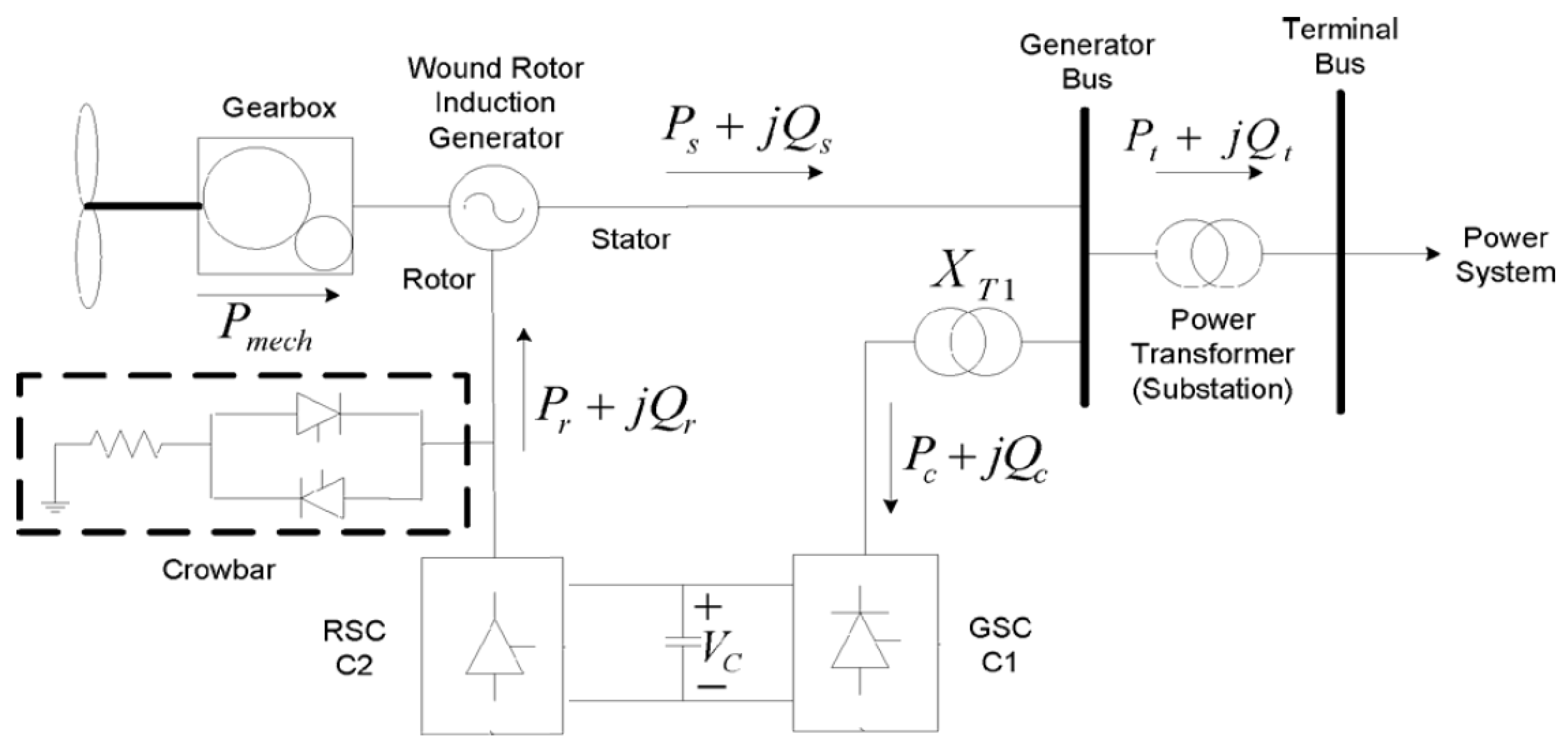
Figure 2.
Voltage at wind generator terminals (Source: ONS).

Figure 3.
Example of a decision tree structure.

Figure 4.
Entropy diagram.

Figure 5.
Offline steps for the decision tree creation process.

Figure 6.
Real-time step scheme dynamic security assessment module based on decision tree.

Figure 7.
Real-time scheme decision tree-based preventive control module.

Figure 8.
Application of a preventive control scheme for local and systemic actions.
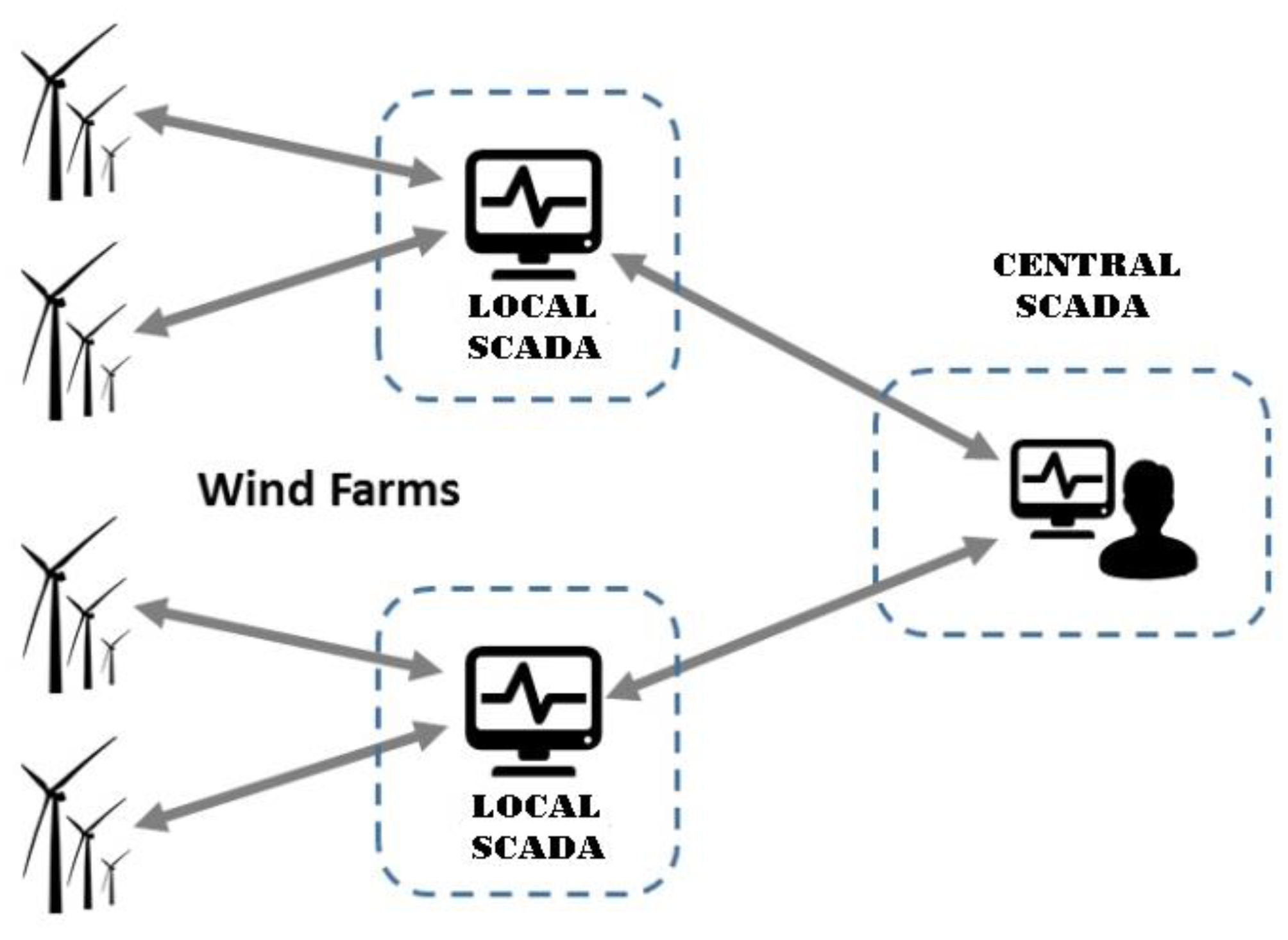
Figure 9.
Application of a preventive control scheme for local and systemic actions.
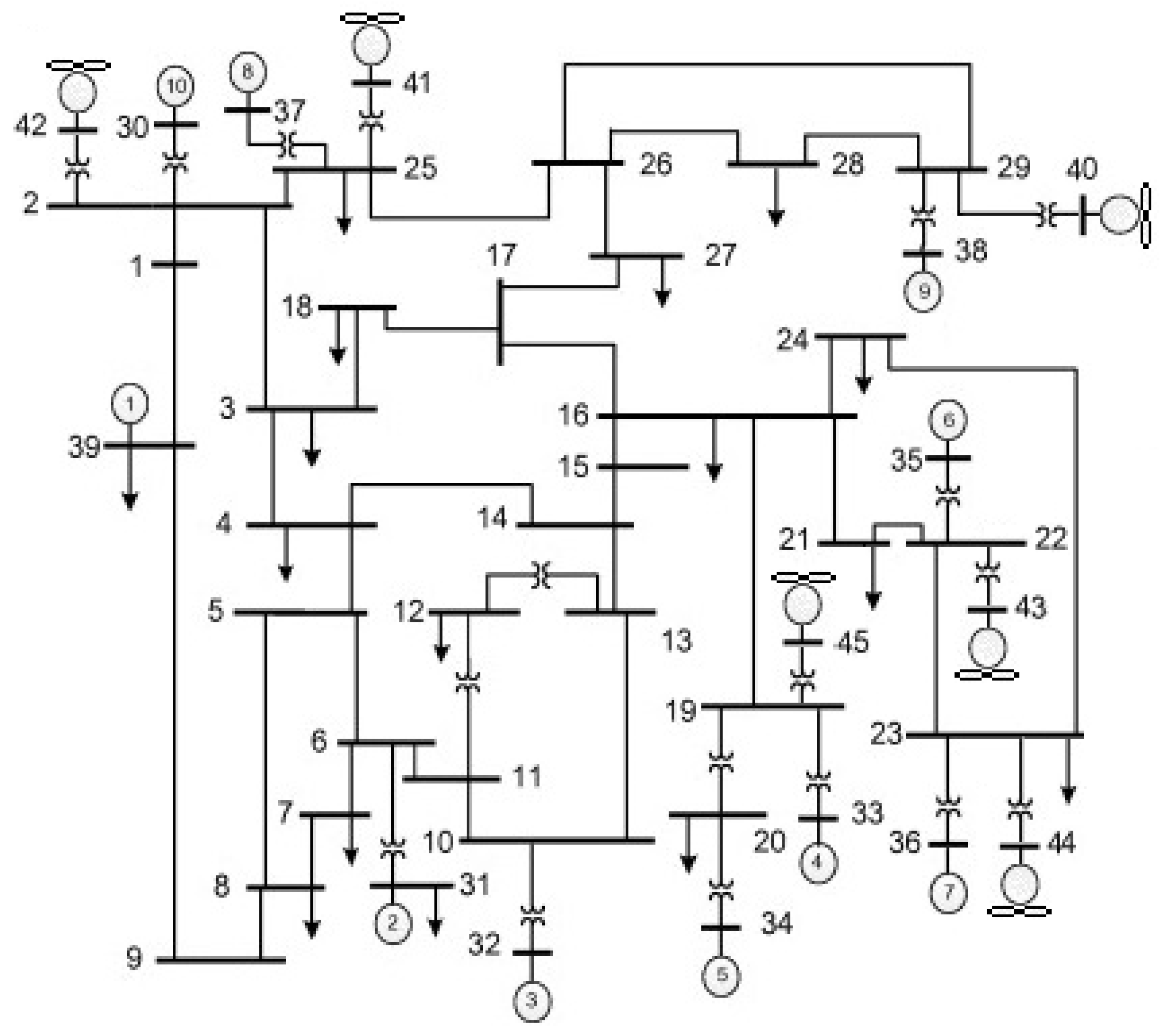
Figure 10.
Decision tree for the application of preventive control during systemic actions.
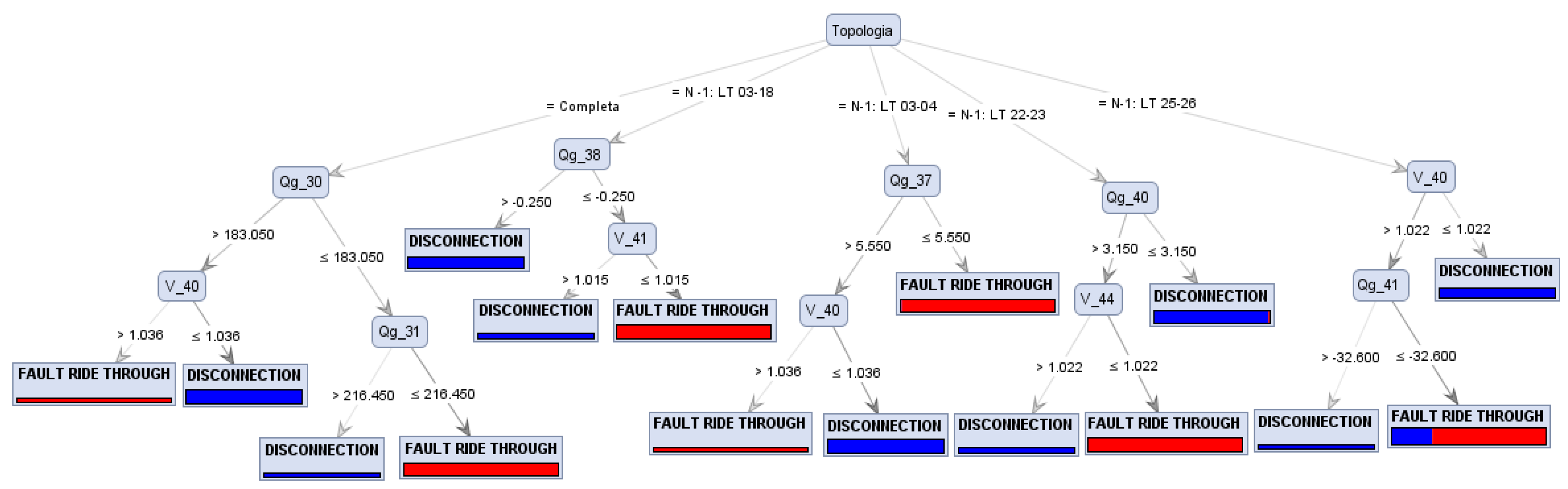
Figure 11.
Decision tree branch for the complete topology.

Figure 12.
Doubly-fed induction generator (DFIG) terminal voltage at bus 40 after a short circuit in line LT 28–29.
Figure 12.
Doubly-fed induction generator (DFIG) terminal voltage at bus 40 after a short circuit in line LT 28–29.
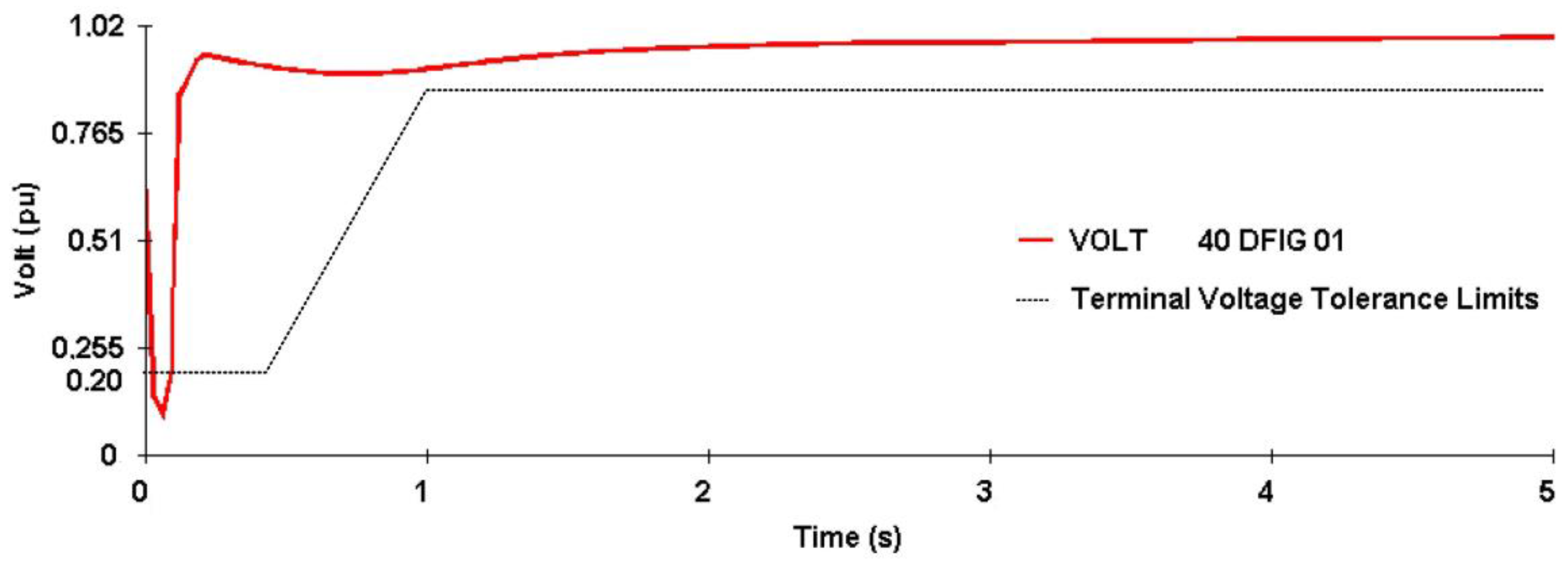
Figure 13.
Terminal voltage of the DFIG at bus 40 after the short circuit with the decision tree (DT) rules and optimization of FLUPOT.
Figure 13.
Terminal voltage of the DFIG at bus 40 after the short circuit with the decision tree (DT) rules and optimization of FLUPOT.
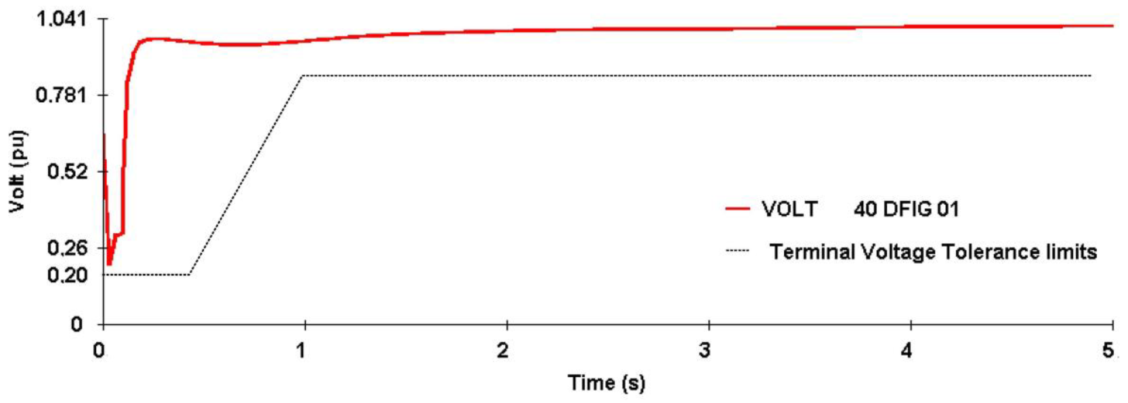
Figure 14.
Decision tree for the application of preventive control during local actions.
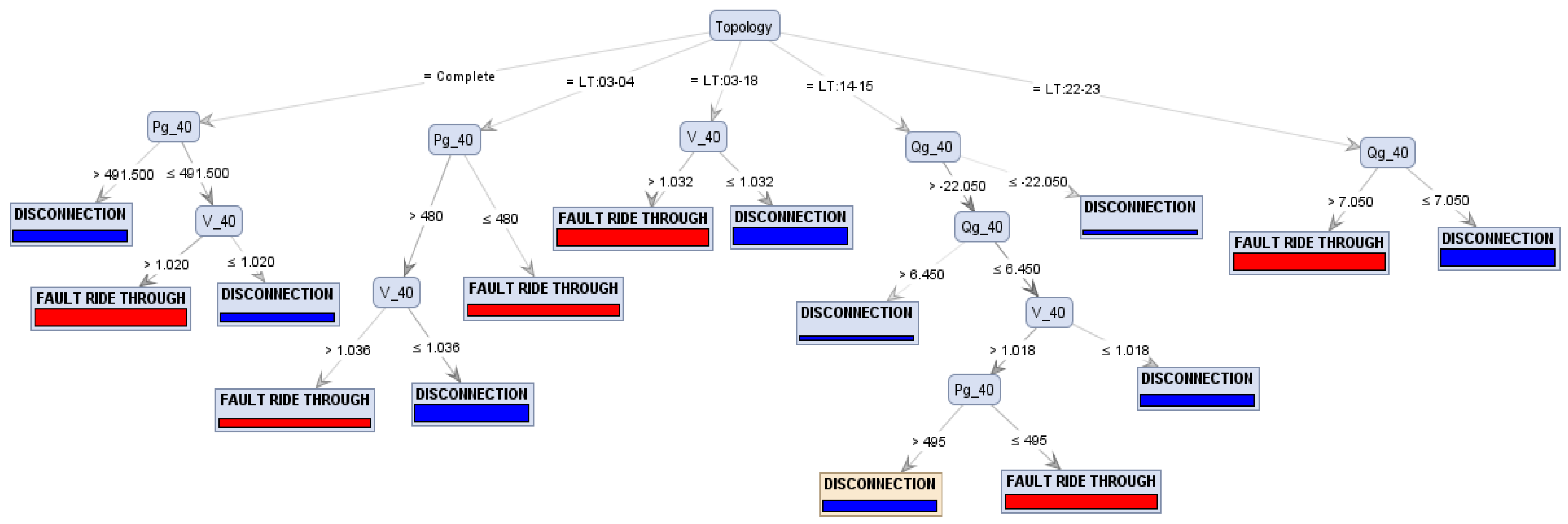
Figure 15.
Decision tree branch for the complete topology.
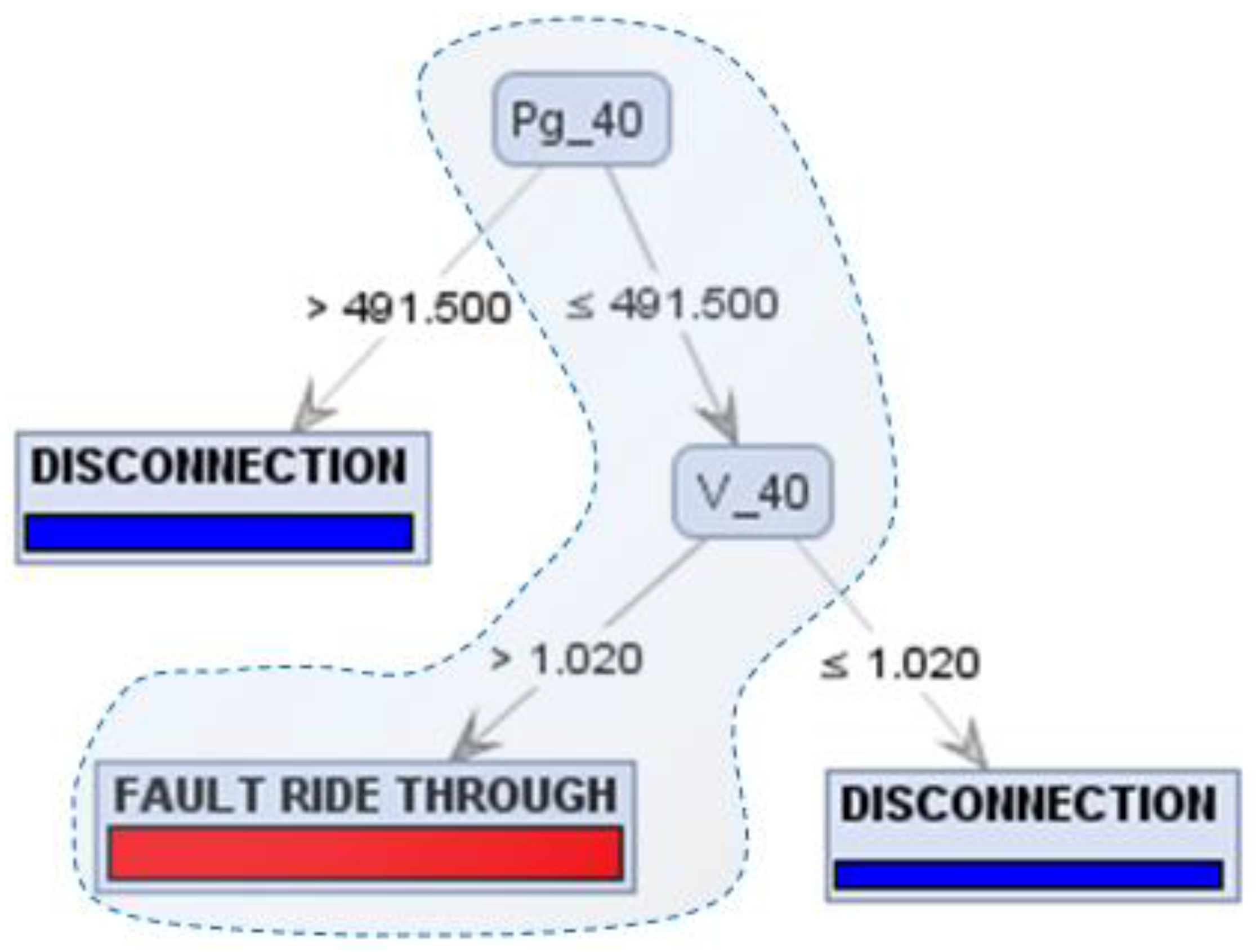
Figure 16.
DFIG terminal voltage at bus 40 after a short circuit.

Figure 17.
Terminal voltage of the DFIG in bus 40 after the short circuit with the DT rules and optimization of FLUPOT.
Figure 17.
Terminal voltage of the DFIG in bus 40 after the short circuit with the DT rules and optimization of FLUPOT.

Table 1.
Systemic database structure.
| Topology | V1 | V2 | Vi | Pg1 | Pg2 | Pgi | Qg1 | Qg2 | Qgi | Atribute |
|---|---|---|---|---|---|---|---|---|---|---|
| Complete | V1 | V2 | Vi | Pg1 | Pg2 | Pgi | Qg1 | Qg2 | Qgi | Disconnection |
| Complete | V1 | V2 | Vi | Pg1 | Pg2 | Pgi | Qg1 | Qg2 | Qgi | Fault Ride Through |
| N-1 | V1 | V2 | Vi | Pg1 | Pg2 | Pgi | Qg1 | Qg2 | Qgi | Disconnection |
| N-1 | V1 | V2 | Vi | Pg1 | Pg2 | Pgi | Qg1 | Qg2 | Qgi | Disconnection |
| N-1 | V1 | V2 | Vi | Pg1 | Pg2 | Pgi | Qg1 | Qg2 | Qgi | Fault Ride Through |
| N-1 | V1 | V2 | Vi | Pg1 | Pg2 | Pgi | Qg1 | Qg2 | Qgi | Fault Ride Through |
| N-1 | V1 | V2 | Vi | Pg1 | Pg2 | Pgi | Qg1 | Qg2 | Qgi | Disconnection |
| N-1 | V1 | V2 | Vi | Pg1 | Pg2 | Pgi | Qg1 | Qg2 | Qgi | Fault Ride Through |
| N-1 | V1 | V2 | Vi | Pg1 | Pg2 | Pgi | Qg1 | Qg2 | Qgi | Fault Ride Through |
| N-1 | V1 | V2 | Vi | Pg1 | Pg2 | Pgi | Qg1 | Qg2 | Qgi | Disconnection |
Table 2.
Local database structure.
| Topology | Vi | Pgi | Qgi | Atribute |
|---|---|---|---|---|
| Complete | Vi | Pgi | Qgi | Disconnection |
| Complete | Vi | Pgi | Qgi | Fault Ride Through |
| N-1 | Vi | Pgi | Qgi | Disconnection |
| N-1 | Vi | Pgi | Qgi | Disconnection |
| N-1 | Vi | Pgi | Qgi | Fault Ride Through |
| N-1 | Vi | Pgi | Qgi | Fault Ride Through |
| N-1 | Vi | Pgi | Qgi | Disconnection |
| N-1 | Vi | Pgi | Qgi | Fault Ride Through |
| N-1 | Vi | Pgi | Qgi | Fault Ride Through |
| N-1 | Vi | Pgi | Qgi | Disconnection |
Table 3.
Wind turbine information.
| Bus Number | Number of Wind Turbines | Maximum Power (MW) |
|---|---|---|
| 40 | 300 | 500 |
| 41 | 180 | 300 |
| 42 | 90 | 150 |
| 43 | 210 | 350 |
| 44 | 180 | 300 |
| 45 | 156 | 260 |
Table 4.
Confusion Matrix (Fault Ride Through Capability (FRTC)).
| Accuracy: 98.67% | Real Class | |||
|---|---|---|---|---|
| - | Disconnection | FRTC | Class Precision | |
| Predicted Class | Disconnection | 143 | 01 | 99.31% |
| FRTC | 03 | 153 | 98.08% | |
| Class Recall | 97.95% | 99.35% | - | |
Table 5.
Confusion matrix.
| Accuracy: 100% | Real Class | |||
|---|---|---|---|---|
| - | Disconnection | FRTC | Class Precision | |
| Predicted Class | Disconnection | 161 | 00 | 100% |
| FRTC | 0 | 139 | 100% | |
| Class Recall | 100% | 100% | - | |
© 2018 by the authors. Licensee MDPI, Basel, Switzerland. This article is an open access article distributed under the terms and conditions of the Creative Commons Attribution (CC BY) license (http://creativecommons.org/licenses/by/4.0/).
Share and Cite
MDPI and ACS Style
Vieira, D.; Nunes, M.; Bezerra, U. Decision Tree-Based Preventive Control Applications to Enhance Fault Ride Through Capability of Doubly-Fed Induction Generator in Power Systems. Energies 2018, 11, 1760. https://doi.org/10.3390/en11071760
AMA Style
Vieira D, Nunes M, Bezerra U. Decision Tree-Based Preventive Control Applications to Enhance Fault Ride Through Capability of Doubly-Fed Induction Generator in Power Systems. Energies. 2018; 11(7):1760. https://doi.org/10.3390/en11071760
Chicago/Turabian StyleVieira, Dione, Marcus Nunes, and Ubiratan Bezerra. 2018. "Decision Tree-Based Preventive Control Applications to Enhance Fault Ride Through Capability of Doubly-Fed Induction Generator in Power Systems" Energies 11, no. 7: 1760. https://doi.org/10.3390/en11071760
Note that from the first issue of 2016, this journal uses article numbers instead of page numbers. See further details here.