Single-Ended Protection Scheme for VSC-Based DC Microgrid Lines

1
Department of Electrical Engineering, Shanghai Jiao Tong University, Shanghai 200240, China
2
Power Grid Technology Centre, State Grid Jiangsu Electric Power Company Research Institute, Nanjing 211103, China
*
Author to whom correspondence should be addressed.
Energies 2018, 11(6), 1440; https://doi.org/10.3390/en11061440
Submission received: 10 May 2018
/
Revised: 27 May 2018
/
Accepted: 1 June 2018
/
Published: 4 June 2018
(This article belongs to the Special Issue Power Electronics in DC-Microgrid Systems)
Abstract
:With the promotion of distributed energy and direct current (DC) loads, the DC microgrid is able to provide a higher power quality and improve the grid efficiency. Various technical issues in DC microgrids are still to be addressed, particularly a proper protection scheme for fault detection and isolation in DC microgrids utilizing voltage source converters (VSCs). In this paper, the pole-to-pole DC fault transient behavior of the VSC-based microgrids is firstly analyzed with four successive stages, and then the exact requirements for protections are presented. Furthermore, a novel single-ended protection scheme based on local transient signals is proposed, which needs no data transmission or synchronization between two ends, ensuring the speed. A four-terminal DC microgrid model was built in PSCAD/EMTDC. Numerous simulations have demonstrated the validity of the proposed scheme.
1. Introduction
DC microgrids provide a highly efficient pattern to combine conventional alternative current (AC) utility powers, distributed energy generators, electronic DC appliances, and energy storage. Compared with AC microgrid systems, the voltage source converter (VSC)-based DC microgrids show many advantages, including a high power-converting efficiency, greater power capacity, better power quality, and thus a lower discarding rate of distributed energies [1,2]. The converters in a microgrid allow the power flow to be bidirectional, catering for the flexible locations of loads and renewable energy. In recent years, plenty of strategies have been proposed for the electronic device design, control module, and optimal operation of DC microgrids [3,4,5,6].
However, various technical challenges still need to be overcome to realize the safe and reliable operation of DC microgrids on a large scale. One of these issues is addressed in the study on the protection principle under DC fault conditions, particularly for the networks with VSCs [7,8]. Conventional converters with thyristors do not experience a high level of overcurrent during DC fault scenarios, whereas in VSCs, insulated-gate bipolar transistors (IGBTs) in converters are blocked as a result of instant self-protection. In this case, the anti-parallel freewheeling diodes together act as an uncontrolled rectifier, allowing the feeding of AC fault current and the discharging of capacitors. These transient stages generate a very large overcurrent, reaching more than 8–10-fold that rated in the worst cases. This overcurrent would flow quickly to all other connected lines if there were no instant protections, posing a great threat to the whole system [9].
In existing AC microgrids, current protection schemes involve the isolation of faulted lines via AC circuit breakers [6,7]. However, these protections are not totally applicable to DC microgrids because of the low impedance of DC lines, as well as the non-existence of zero crossings in DC current signals. Therefore, it is necessary to investigate a novel protection scheme aimed at DC microgrids, to detect and isolate only the faulted segments, thus protecting large numbers of power electronic devices in converters, and meanwhile maintaining the power supply security in healthy areas [10,11]. In recent years, DC circuit breakers have been utilized in low-voltage DC microgrids, and double-ended DC line protections are gradually being put forward [12,13,14]. Usually, methods using double-ended signals and data processing in the frequency domain are more accurate [15,16]. However, single-ended schemes are advantageous in the accessing of local measurements, no need for synchronization, and lower industrial cost. Voltage and current signals are preferred in protection designs for microgrids, as these data are originally restored in the line terminals. The authors in [17] propose a new single-ended differential protection using data measured from distributed optical sensors along the transmission line. A novel single-ended protection principle based on time-domain transient electrical signals is proposed in [18], where the DC line current change and voltage change rate are used as criterions.
In this paper, the basic structures of DC microgrids are firstly introduced. The pole-to-pole fault transient characteristics of VSC-based DC microgrids are then analyzed in four stages. A novel protection scheme is proposed using the single-ended transient signals. In the proposed scheme, the voltage criterion of DC inductance is employed as a directional element, which can identify forward faults of the protected line. Features of the pole voltage change criterion are used as the pole selection element, through which the faulted pole can be distinguished. This method needs no communication between the two ends, ensuring the speed and reliability. Finally, various simulation results demonstrated the validity of the proposed protection in PSCAD/EMTDC.
2. Pole-to-Pole Fault Characteristics of DC Microgrids
2.1. Structures of DC Microgrids
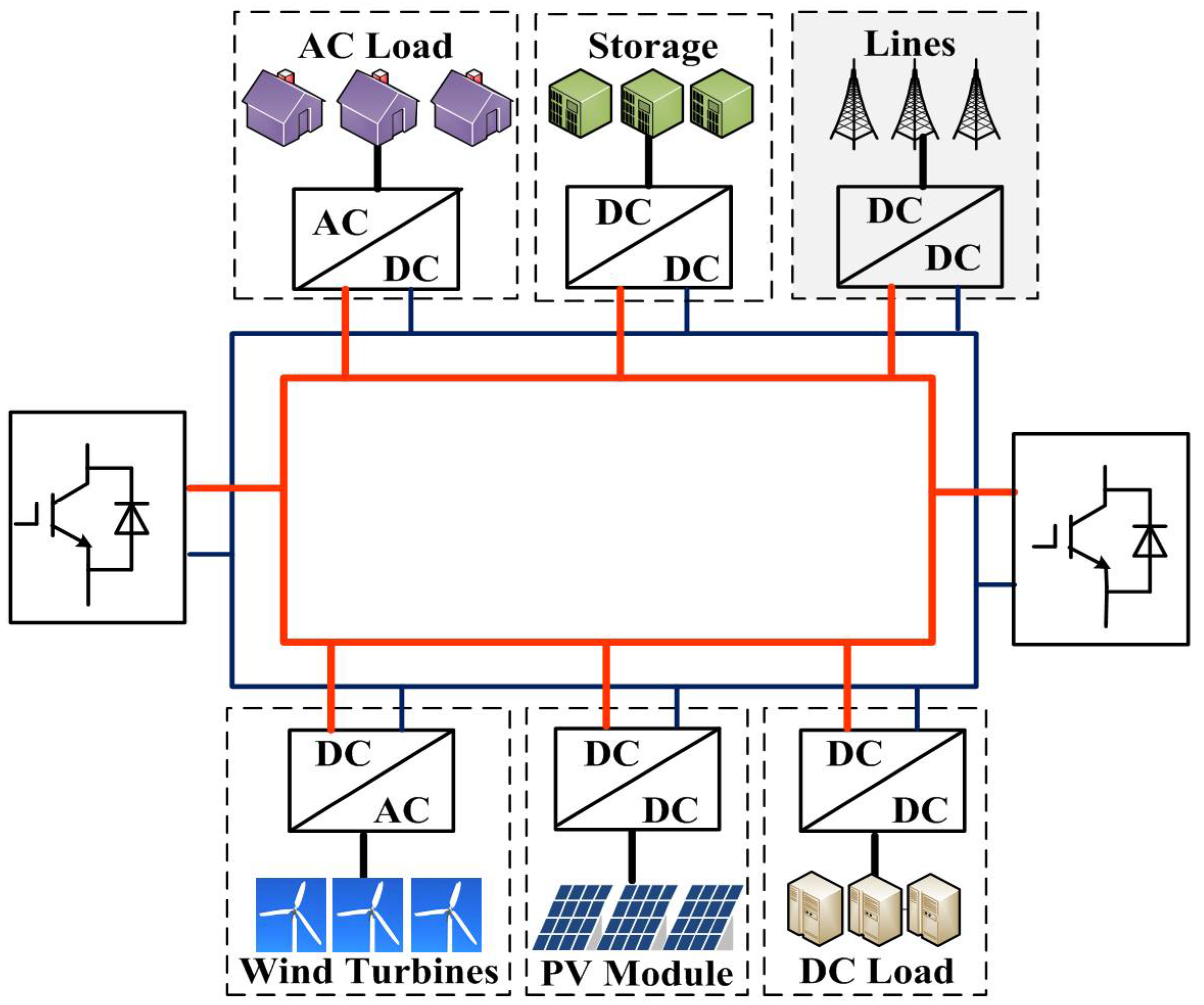
The scale of a DC microgrid has a strong relationship with its location, construction purpose, and the number of connected distributed generations. In general, DC microgrid networking is very flexible with regard to its plan, design, control, and operation. Figure 1 shows the radial structure of a multi-terminal DC microgrid, and Figure 2 shows the ring structure, the grey zone indicating adjacent lines. As a result of its reliable and flexible operation, the ring structure is more commonly used in multi-terminal systems [15,16]. Sources in a DC microgrid could be of various types. Photovoltaic modules and fuel cells provide DC voltage, which makes these sources suitable to be connected via a DC/DC converter. Microturbines featuring high-frequency voltage depend on conversions to join in the DC grid. AC/DC converters are also needed when connecting wind turbines to DC buses. Besides sources, some energy storage devices such as batteries and supercapacitors are crucial to microgrids for their functions of power-quality improvement, load leveling, and an emergency power supply [19]. Additionally, DC microgrids are also able to supply AC or DC loads in need of high reliability, for example, monitoring systems, safety systems, and equipment for ventilation or heat [20].
It is illustrated that both AC/DC and DC/DC converters are used in the system to interconnect the different modules to the DC bus. These AC/DC converters are required to generate a sinusoidal voltage and current wave, to transmit the power flow bidirectionally. The converters should be galvanic isolated and able to deal with imbalance or voltage dips. In this case, the VSC is a preferable alternative to improve the efficiency of conversion.
2.2. Fault Transient Stages
The extensive usage of VSCs brings about the issue of fault analysis and the protection principle, a vital part of microgrid systems [21]. Faults on the DC side consist mainly of pole-to-pole faults, pole-to-ground faults, and break faults, which should be detected as quickly as possible. Pole-to-pole faults raise the most concern among these types, as severe transient characteristics may lead to destructive consequences, on both the DC and AC sides. For this reason, the proposed protection scheme is based on detailed insight into DC faults, which is discussed in this section.
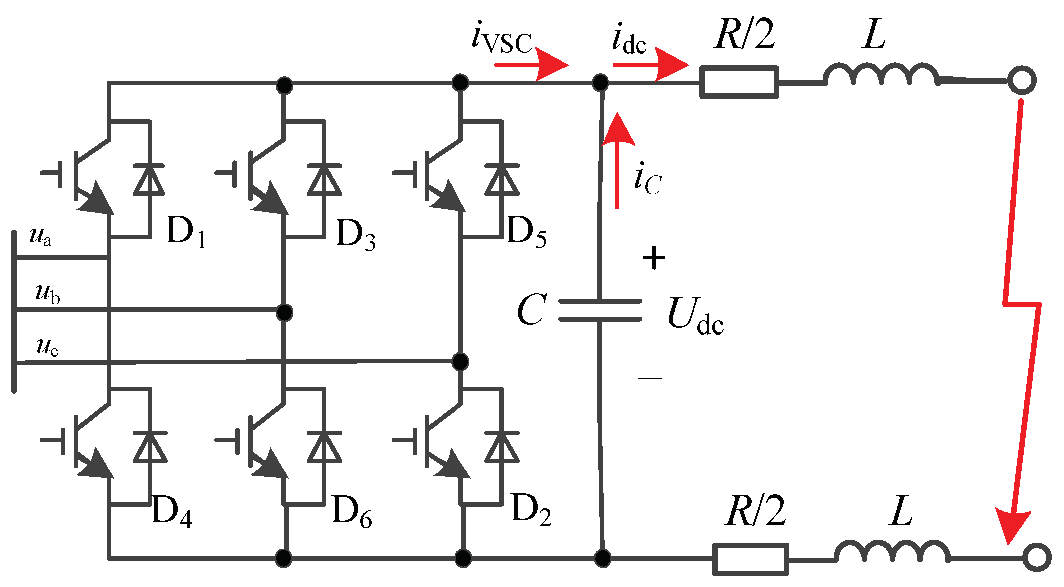
Figure 3 shows the equivalent circuit of a pole-to-pole short-circuit fault in a DC microgrid, where R and L represent the equivalent resistance and inductance of the DC line, respectively; C represents the paralleled DC capacitor; and ua, ub, uc represent the AC voltage connected point. Under this fault condition, the capacitor discharges through the fault point (iC). As for the AC system, it is collapsed to a three-phase short-circuit because of the low impedance of DC lines. The converter is then blocked by its overcurrent protection. Therefore, the AC power would feed in the fault point through the parallel diodes in the VSC (iVSC) [18,19]. Because the equivalent circuit is nonlinear, it can be divided into four stages in detail for the mathematical analysis, as shown in Figure 4.
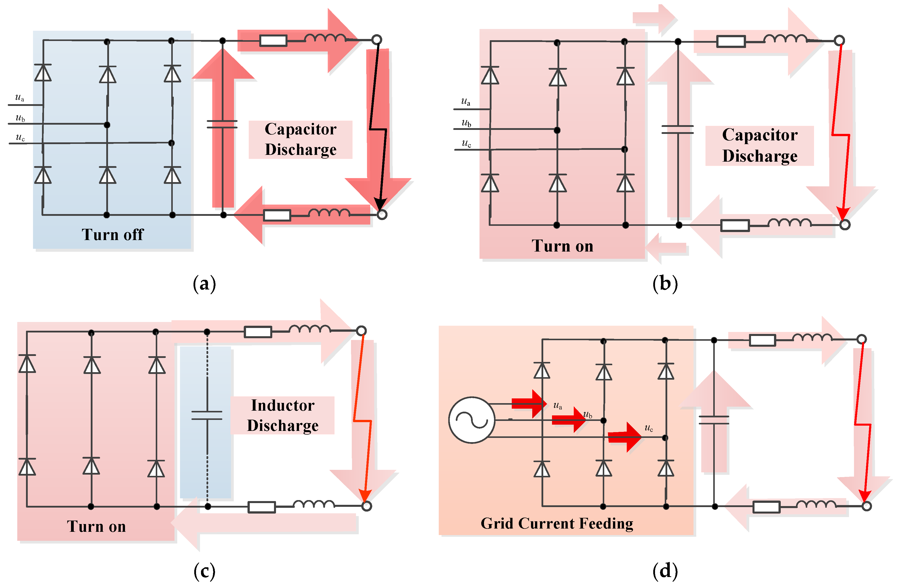
As shown in Figure 4, the DC fault current has two energy sources in principle: the connecting AC grids, which contribute to a steady-state fault current through the VSC, and the DC capacitor, which contributes largely to a transient current. The DC capacitor discharges rapidly during the bipolar fault when the IGBTs are blocked, contributing to a large DC current. The AC voltage is normally smaller than the DC voltage, which leaves the diodes turned off at the very beginning.
2.3. DC Fault Analysis of VSC
As shown in Figure 4, stage 1 has an overcurrent through the DC lines without the joining of the AC system. The discharging circuit in Figure 4a can be described as a second-order transient equation of the DC voltage:
To solve this equation, the parameters R, L, and C play a part in the expression. For a DC microgrid system, the resistance of DC lines is relatively small enough to fulfill the underdamping condition . In this case, the eigenvalues of the nonlinear Equation (1) are a pair of conjugate complex numbers in Equation (2). Supposing the pole-to-pole fault happens at t = 0 with the initial conditions U0 and I0, the fault voltage and current can be solved as follows:
where , , , and .
For DC microgrids, particularly when additional DC inductances are installed at the terminals, line parameters satisfy the condition (R/2L)2 < 1/LC in Equation (4) if a metallic fault occurs, indicating . The DC fault current of Equation (4) can therefore be rewritten simply as follows:
Assuming , the DC current can be clearly seen as a function of initial states and line parameters L and C in Equation (6):
When the voltage of the capacitor drops to the same level as the AC link, it reaches stage 2, at which point the diodes turn on because of the forward voltage. Meanwhile the capacitor continues to discharge. The time at which the voltage of the capacitor discharges to zero can be obtained as follows:
where .
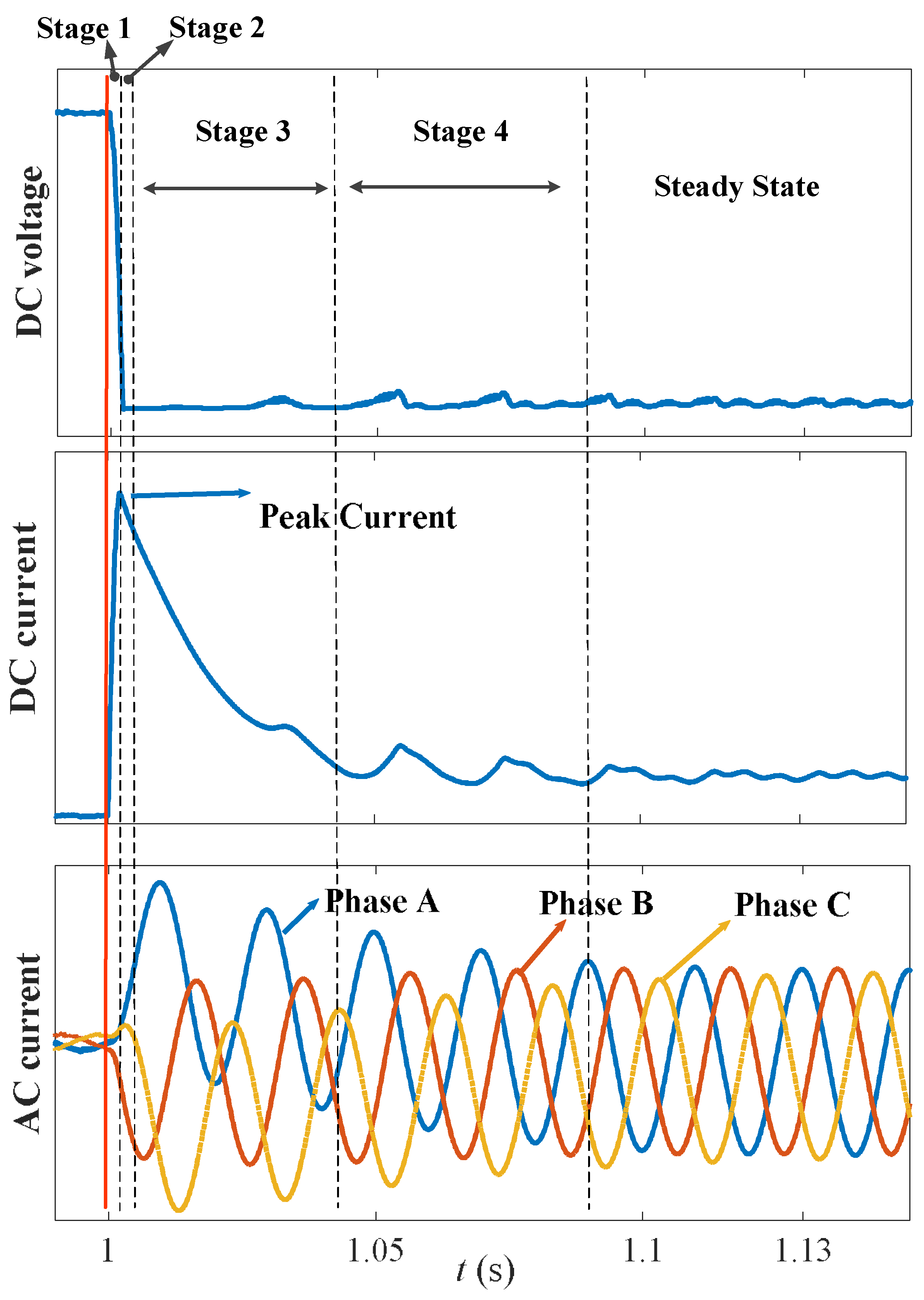
Figure 5 illustrates the transient waveforms responding to a pole-to-pole fault at t0 = 1 s, with the four stages each labeled.
Stages 1 and 2 last several milliseconds, and during these stages the transient features are used to compose protection schemes. Some interesting features in stages 3 and 4 may be noticed. As the DC voltage becomes less than zero because of the damping, the inductor discharges through diodes and resistance, again charging the capacitor in stage 3. With the increase in the capacitor voltage, the DC voltage between the two poles slightly rises from zero. At this time, the AC grid performs as a three-phase fault with current increasing sharply. In stage 4, the AC grid current feeds in the DC link through paralleled diodes, posing a great threat to electronic devices. In general, DC faults should be cleared in 3–5 ms to avoid the collapse of the system and thus the restart of the VSC (charging, synchronization, etc.), which may otherwise take a long time in the order of seconds.
3. Single-Ended Protection Scheme
3.1. Requirements for Protection
The DC microgrid is featured with low inertia and is connected with many distributed energies and AC/DC loads. Figure 5 shows that the DC voltage drops dramatically in 2 ms during the fault, which demands a fast protection to be detected. Therefore, the DC protection should utilize the transient characteristics to distinguish the faults as quickly as possible, which means the action by the protection should be between stages 1 and 2 when the capacitor discharges.
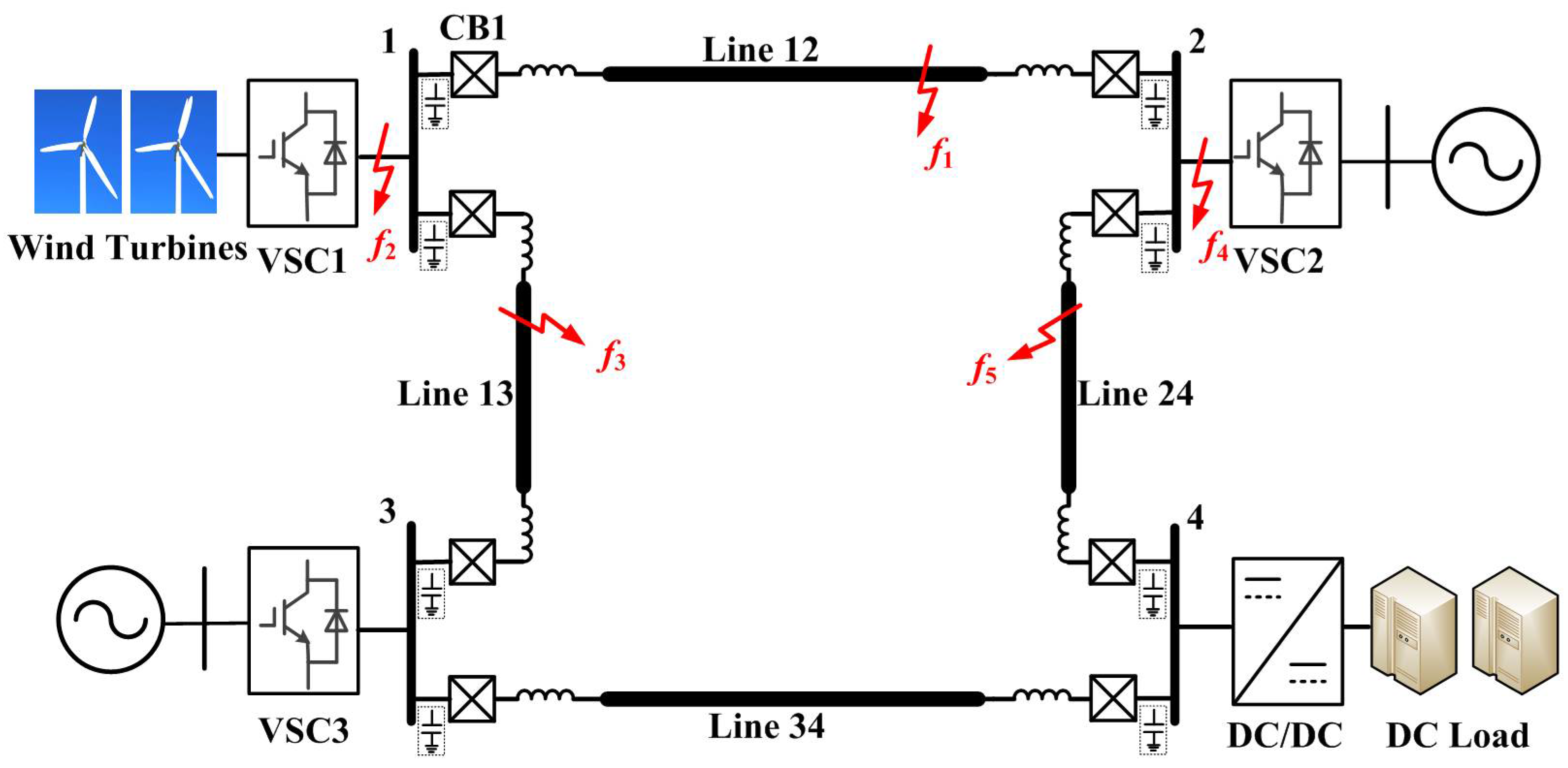
A multi-terminal VSC-based microgrid DC system is shown in Figure 6, for which wind turbines and a DC load are connected to the DC buses. The paralleled DC capacitors are used to stabilize the DC voltage. The supplemental inductors are installed at each end of DC lines, which could reduce the peak value and rising rate of the fault current to a lower level. These supplemental inductors naturally act as the boundary of DC lines, blocking the high-frequency components of current. Meanwhile, these boundary cells could be used to extract information to reliably distinguish between the internal faults and external faults.
Considering the protection at CB1 in Figure 6, for example, the fault locations are illustrated: f1 suggests an internal fault, f4 and f5 suggest external forward faults, and f2 and f3 suggest backward DC faults. The role of protection at CB1 is to ensure the power transfer security and stability of the system under DC fault conditions. This is achieved by isolating the faulty segments in such way that the remaining healthy part operates normally. The characteristics of the terminal fault f1 on line 12 are very similar to those of the terminal fault f5 on line 24. In this aspect, the protection should be selective enough, sufficiently fast, reliable, and robust. In general, the transient characteristics of DC capacitors and inductors are important for designing a single-ended protection scheme. The scheme should satisfy the selectivity, speed, sensitivity, and reliability simultaneously. The action of protections should be made in 2 ms at stages 1 and 2.
3.2. Startup Component
In a DC microgrid, it is desirable to use only local signals to detect faults because of the sharp increase in fault DC current during the first two stages when the DC capacitor discharges. If the local controller can distinguish this feature accurately, the startup signal could be transmitted to the local DC breaker without data communications between the two ends, which is very advantageous in terms of saving time, contributing to the fast detection of faults. Hence the absolute-value integration method is adopted as the startup component, as formulated in Equation (8):
where Ik indicates the measured current, and k = 1, 2, …, N. N is the total number of sampling points in the time window. Iop_set indicates the setting value, where normally Iop_set = Krel Irate Krel, the reliability coefficient, is equal to 1.3–1.5, and Irate is the DC current rating.
3.3. Directional Criterion
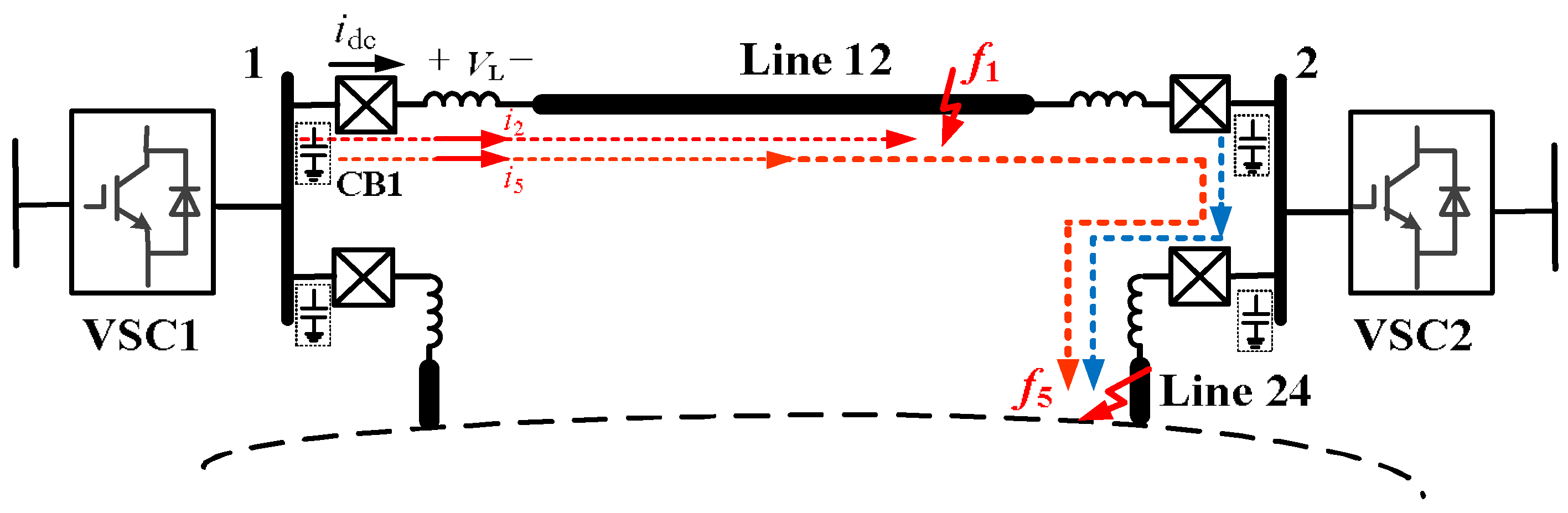
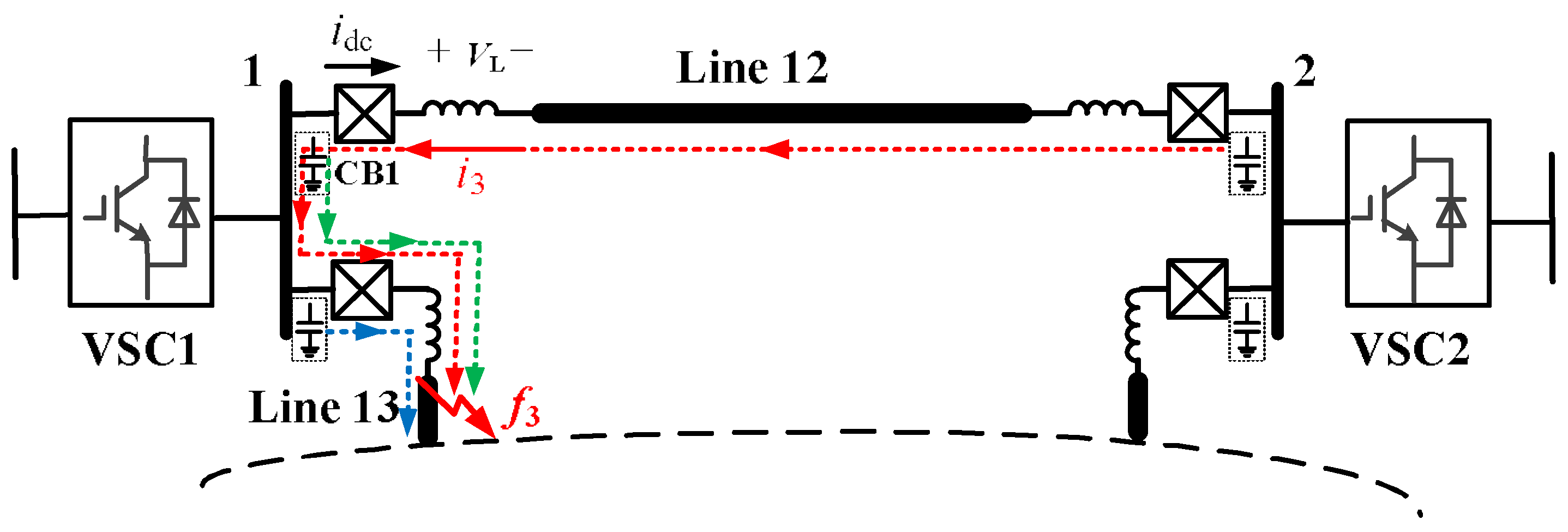
A proper directional criterion is important for the protection scheme for multiterminal systems. Figure 7 shows forward pole-to-pole faults at two locations for CB1. The current through the inductor flows from the bus to the line, which is the same direction as for the reference current idc. For the backward fault in Figure 8, however, the inductor current flows in the other direction. This paper proposes a practical directional criterion utilizing the voltage over the supplemental inductor to distinguish the forward faults from the backward faults, formulated as follows:
where VL is the voltage of inductance L, and idc is the reference current through the inductor as labeled in Figure 7 and Figure 8.
To further investigate the voltage in Equation (9), the DC current in Equation (6) can be used to achieve the derivative of the DC current at the fault time t = 0 as follows:
The sign of Equation (10) depends on the sign of as follows:
If faults happen with an initial current I0 of less than zero, that is, , then can hence be derived, which means the changing rate (Equation (10)) is greater than zero.
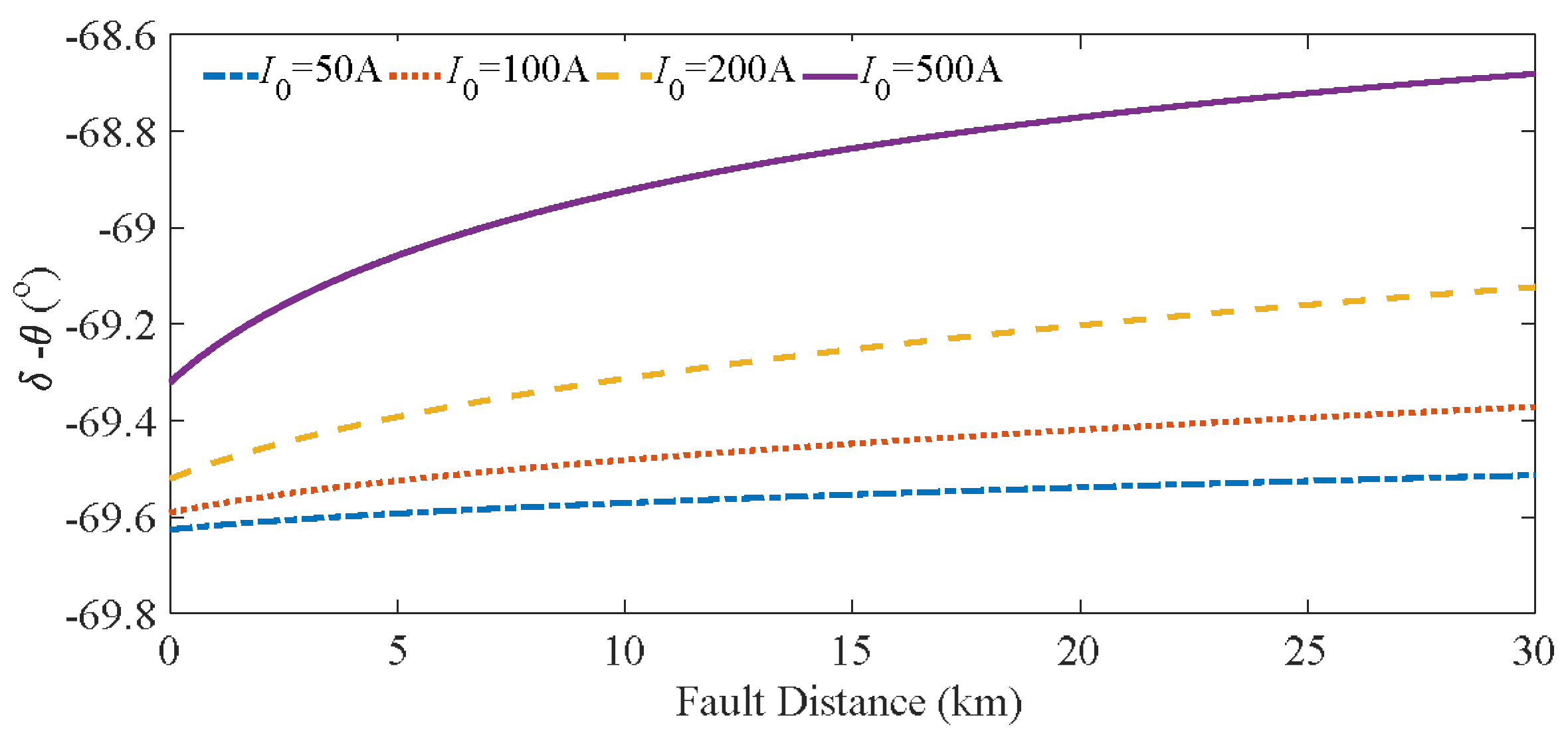
On the other hand, if faults happen with an initial current I0 of greater than 0, the relationship between these two angles in Equation (11) should be further determined. Here some simulations using parameters from the projects were investigated, as shown in Figure 9. A typical group of parameters from a DC microgrid were chosen: U0 = 1000 V, L0 = 0.56 mH/km, R0 = 0.078 Ohm/km, Lr = 1 mH, and C = 2 mF. The fault distance varied from 0 to 30 km, and the initial current varied from 50 to 500 A. The mathematical analysis results show that the angle was always around −69° to −70°.
Because the angle in Equation (11) is less than zero regardless of the initial current and fault distance, the changing rate of the DC current in Equation (10) is always greater than zero, making the DC voltage of the inductor also greater than zero. For backward faults, however, the current reverses the direction and similarly increases, with the inductor voltage being less than zero. Thus, the direction criterion of the proposed protection scheme is that composed in Equation (12):
3.4. Faulted Pole Selection
Faulted pole selection is an essential step in protection schemes that allows the power transfer security among healthy segments. In this paper, the transient characteristics of pole DC voltage are used to identify faulted poles.
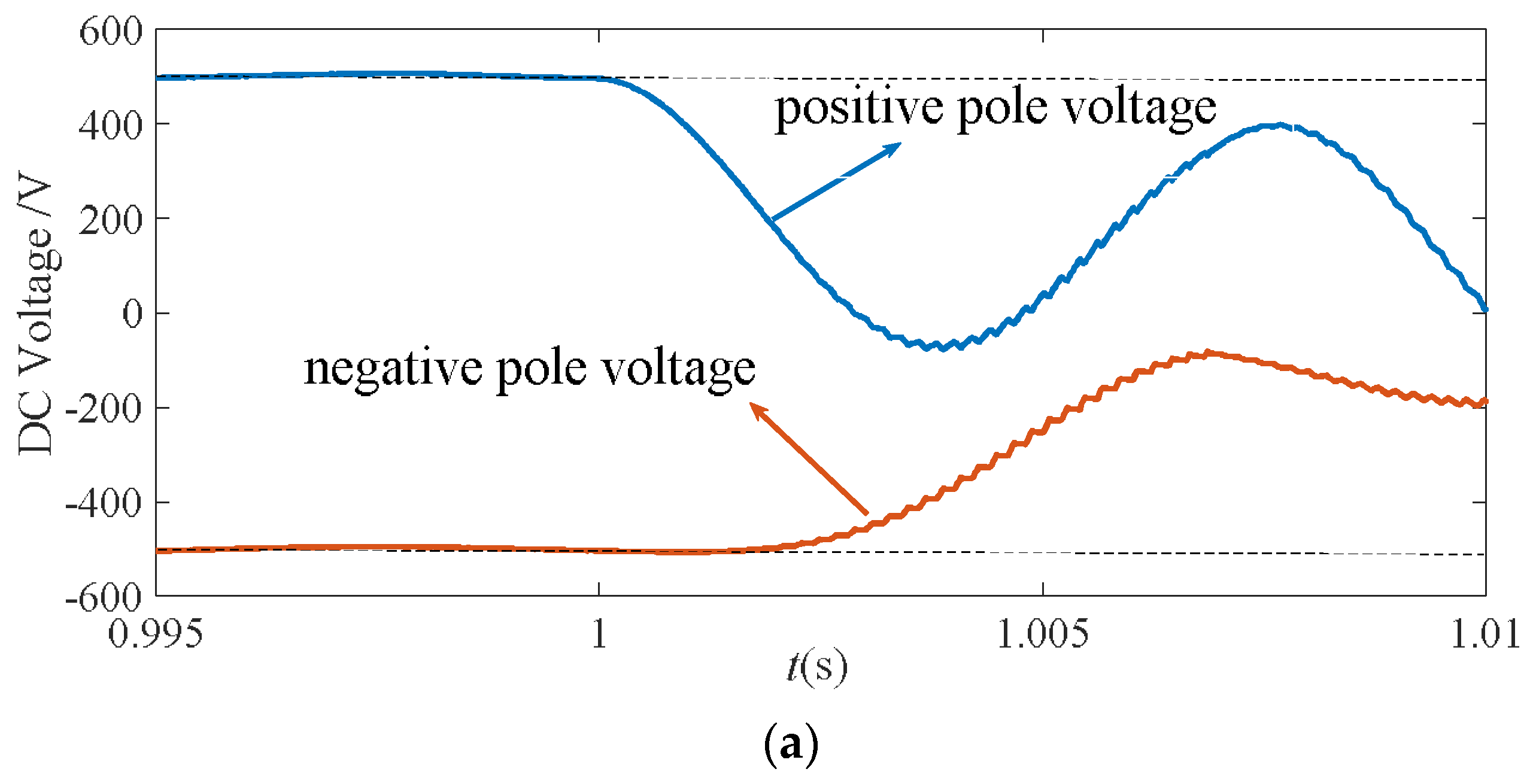
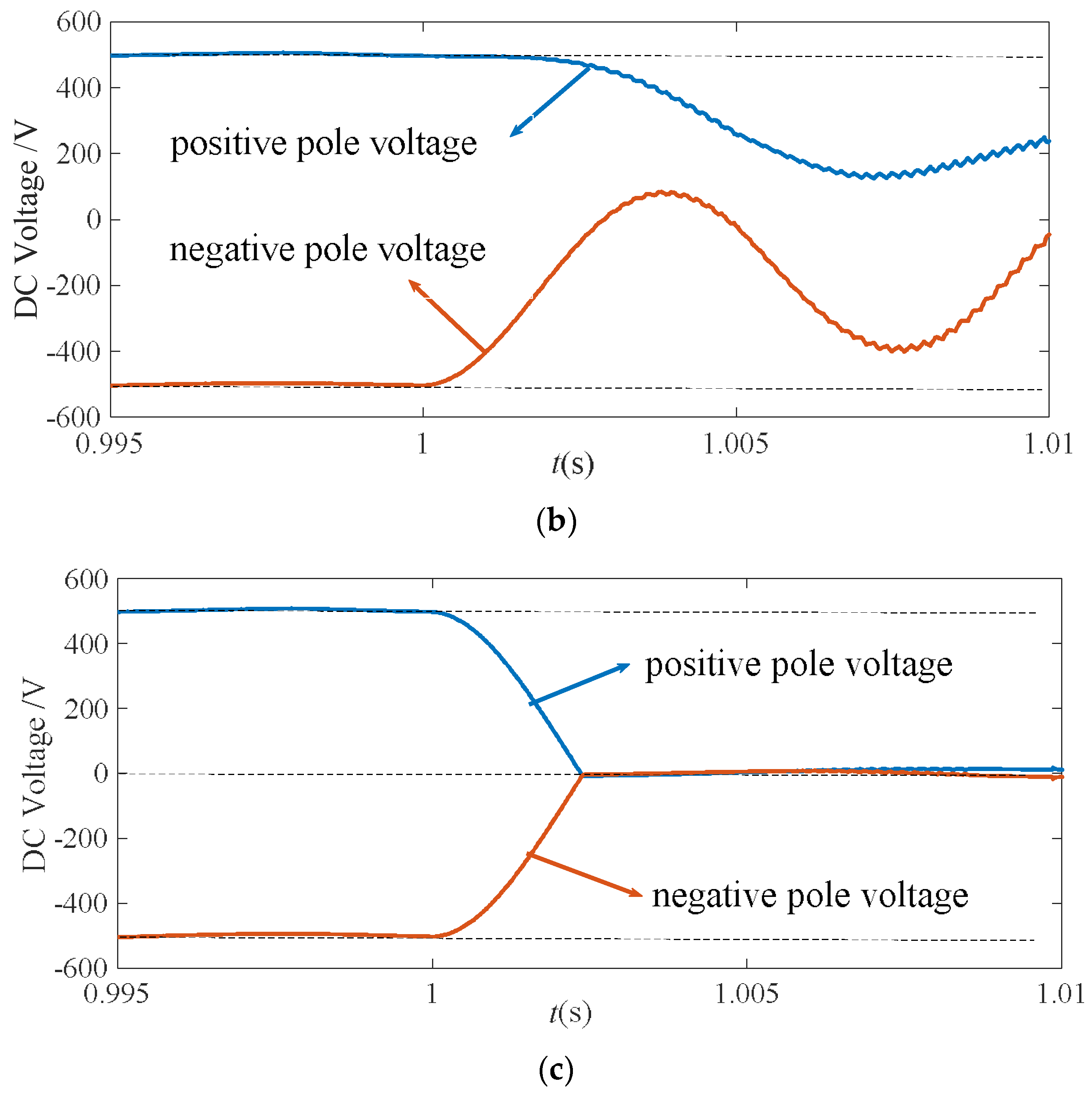
As presented in Section 3, when a pole-to-pole fault occurs, the voltages of both poles decline at the same rate, in principle, whereas when a pole-to-ground fault happens, a faulted pole experiences a higher changing rate. During a positive-pole-to-ground fault, the positive-pole voltage drops to zero at a rate faster than that of the negative-pole voltage. Similarly, the negative-pole voltage rises to zero at a rate faster than that of the positive voltage during a negative-pole-to-ground fault, as illustrated in Figure 10, where the dashed lines are voltage rating ±500 V and zero reference.
The coefficient of the changing rate of pole voltage (CRU) is introduced to quantify the changing characteristics of the transient pole voltage waveform.
where CRU+ and CRU− represent the change rate coefficients of positive and negative pole voltages, respectively; KU is the ratio of CRU+ to CRU−; u+(k) and u−(k) represent the kth samples of positive and negative pole voltages, respectively; u0+ and u0− represent the initial voltages; N represents the number of samples in the time window of 2 ms; and the corresponding N is equal to 100 for the sampling frequency of 50 kHz.
The CRU+ coefficient is much greater than CRU− for a positive-pole-to-ground fault, ; on the other hand, CRU+ is much smaller than CRU− for a negative-pole-to-ground fault, . When a pole-to-pole fault happens, can be concluded theoretically. The ratio KU, therefore, can be taken as a faulted pole selection criterion in Equation (14). This criterion was generally useful in the various simulations, as an adequate margin was considered. To guarantee its reliability in industrial project usage, a further field test with project parameters is recommended.
3.5. Identification of Fault Areas
The forward faults f2 and f5 have similar features, as explained above. This section proposes a criterion to identify an internal fault on the basis of the idea of distance protection. For a pole-to-pole fault, at a distance x from CB1 on line 12, the time-domain equation containing the distance is Equation (15):
where L0 and R0 are the inductance and resistance per kilometer of lines, respectively; Lr is the supplemental inductance; and ut is the local measured voltage. The shunt capacitor of the line has been omitted for its limited contribution. The fault distance can then be solved for as follows:
For positive-pole or negative-pole-to-ground faults, the distance can also be similarly written as follows:
Here, the time window is 2 ms and the sampling frequency is 50 kHz, ensuring a sufficient number of data samples to obtain the fault distance. The line protection zone is generally set to be 90% of the whole line, and thus the internal fault criterion in this paper is set as
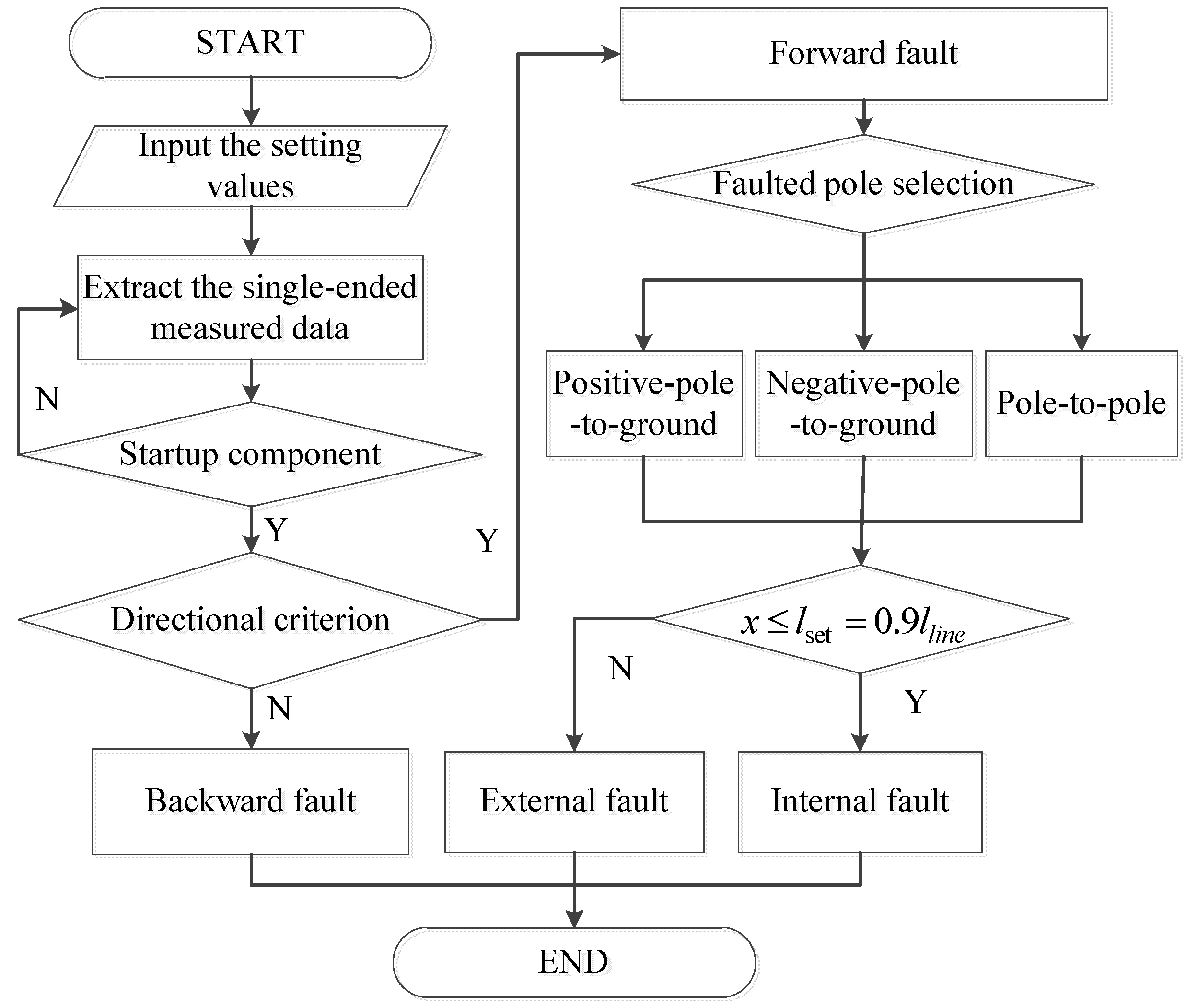
To conclude, the flowchart of the proposed single-ended DC fault protection scheme is illustrated in Figure 11.
4. Verification
The four-terminal DC microgrid of Figure 8 was established in PSCAD/EMTDC to test the proposed single-ended protection scheme. The system parameters were the same as those stated in Section 3.3: the nominal voltage was ±500 V, and four 1 km lines were used with the π-model.
4.1. Simulation of Directional Criterion
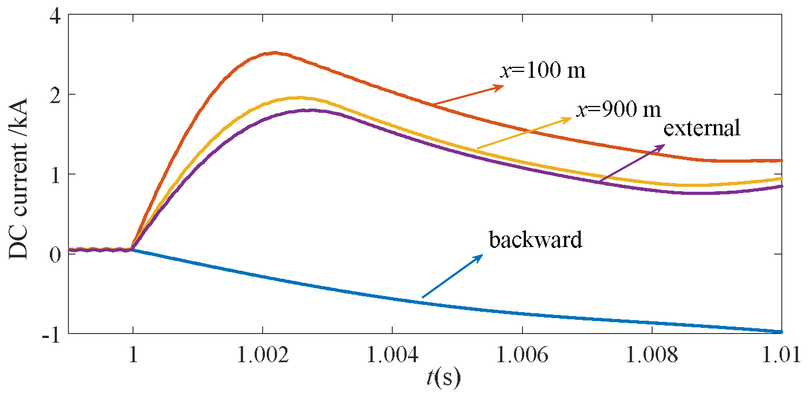
Figure 12 illustrates the simulation results for the DC current of pole-to-pole faults at different locations. The reference forward direction of CB1 was set from the bus to the line. From the picture, it is seen that the rising rate of the fault current was reduced, because of the placement of supplemental inductors at both ends of the lines.
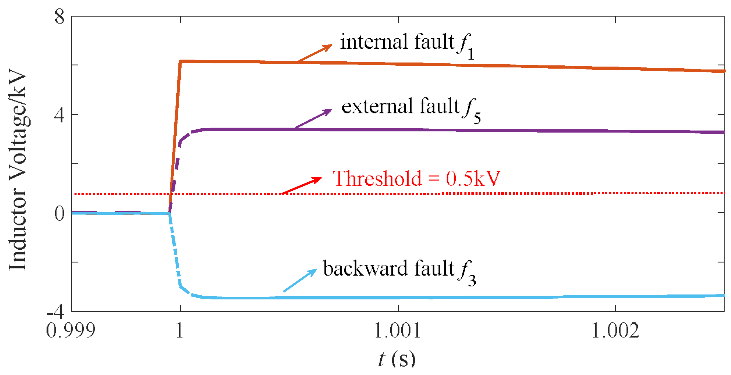
The simulation results for the three fault types in Figure 8 and Figure 9 are shown in Figure 13. The forward faults were the following: the internal fault f1 at the terminal end (fault distance x = 900 m) of line 12, and the external fault f5 at line 24 close to VSC2. The backward fault f3 was located at line 13, which was near VSC1. As is seen from the results, the directional criterion could selectively distinguish the forward faults and backward faults by the threshold of 0.5 kV, the dashed line in Figure 13.
4.2. Simulation of Faulted Pole Selection
The results of the faulted pole selection for CB1 are displayed in Table 1. Here, the internal faults were located on line 12 and the external faults were set on line 24. The fault distances were 100, 500, and 900 m, respectively. The fault resistances were 0.1 and 1 Ω, respectively, as the line was 1 km in length and the DC voltage was rated at 1000 V.
The calculated KU values were all greater than 1.3 for positive-pole faults-smaller than the setting value of 0.7 and around 1.0 for pole-to-pole faults, which is demonstrated by Equation (14). The proposed faulted pole selection criterion works properly, regardless of the fault resistance and fault distance.
4.3. Simulation of Fault Area Identification
The distance criterion was used to primarily identify the internal faults and forward external faults following the faulted pole selection. Similarly, various distances and fault resistances were considered for PG faults, NG faults, and PP faults. The results are shown in Table 2, where the internal and external faults are identified correctly.
In this section, the protection zone of the proposed scheme was set as 90% of the length of the whole line. Hence the remaining part should be covered by the backup protection, which was added with a time delay.
4.4. Sensitivity Analysis
4.4.1. Influence of Signal Noise
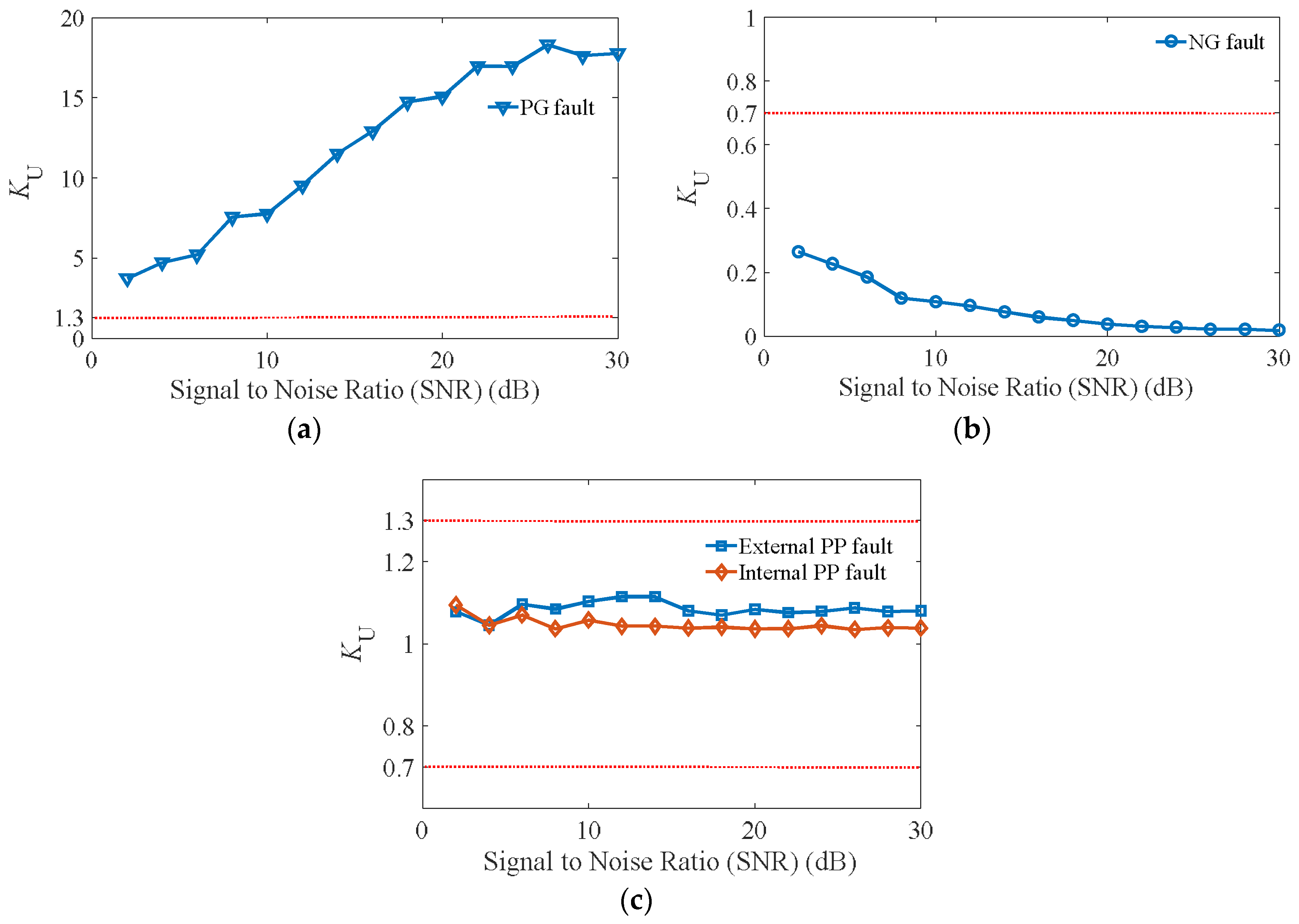
This section investigates the impact of signal noise on the proposed protection. The three types of internal faults at the middle of line 12 and the external PP fault on line 24 were simulated. White Gaussian noise was added to the sampling voltage in various levels, with a maximum of 30 dB. Then, the protection scheme was employed. The simulation results for the protections on line 12 with different signal-to-noise ratios (SNRs) are presented in Figure 14. As shown in Figure 14, the ratio KU was still greater than 1.3 for PG faults and smaller than 0.7 for NG faults even with the high level of additive noise. Meanwhile, the ratio for PP faults did not exceed either of the two thresholds. The results demonstrate that the proposed protection scheme has a high robustness to additive noise.
4.4.2. Influence of Sampling Frequency
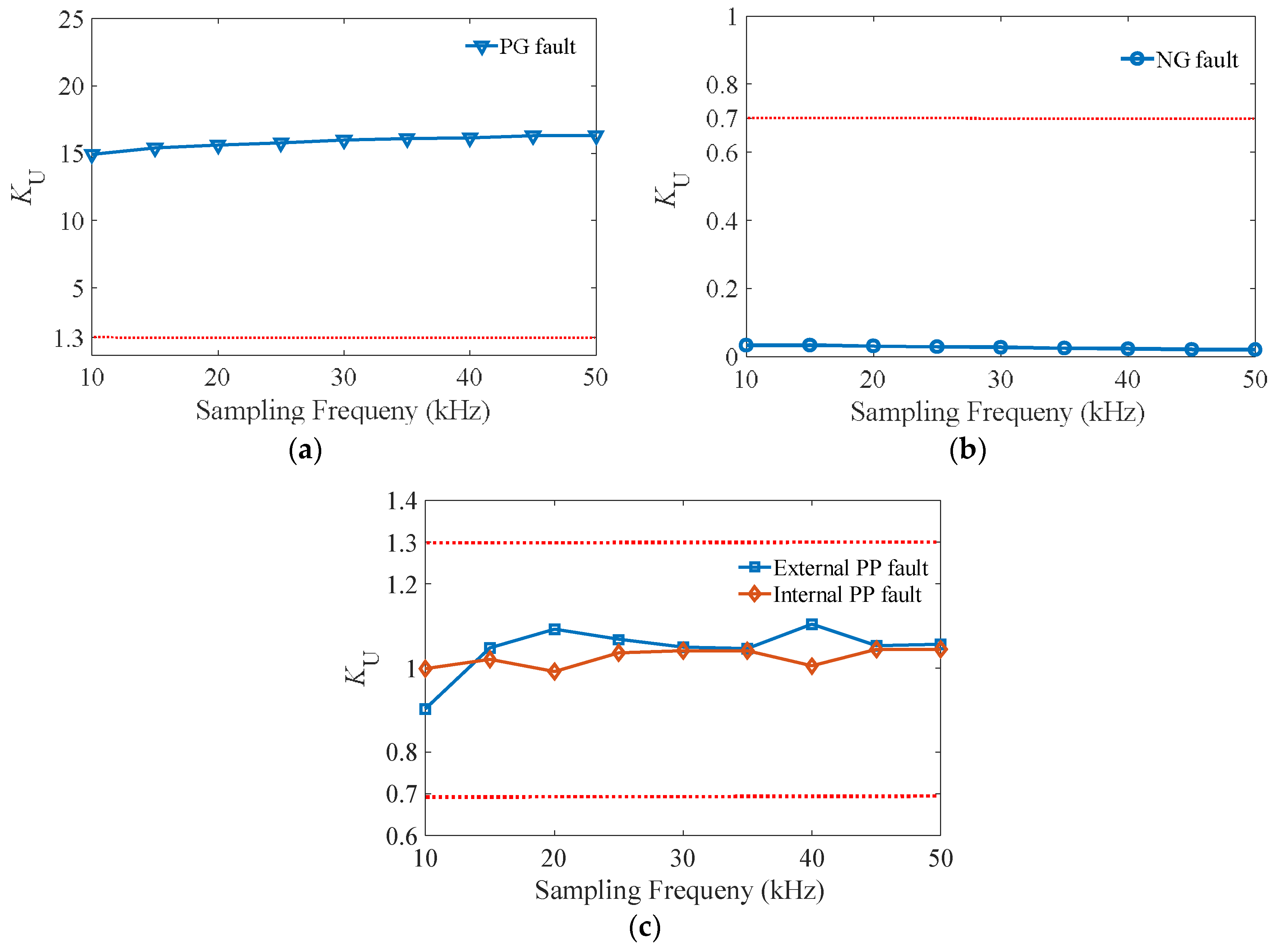
The impact of the sampling frequency on the proposed scheme could be analyzed by down-sampling the DC voltage signals. The frequency band in this section was from 50 to 10 kHz. The internal faults were simulated at the middle of line 12, while the external fault happened on line 24, with a fault resistance of 0.1 Ω. The KU value calculated by the pole voltages at CB1 are presented in Figure 15. It is seen that KU was greater than 1.3 for PG faults and less than 0.7 for NG faults, even with a low level of sampling frequency. Meanwhile, the ratio for PP faults did not exceed either of the two thresholds. Therefore, the proposed protection scheme performs well, undisturbed by the sampling frequency.
5. Conclusions
In this paper, pole-to-pole fault characteristics for VSC-based DC microgrids are investigated, and four transient stages are quantitatively analyzed. On the basis of single-ended transient signals, a protection scheme for DC lines in microgrids is proposed to act as the main protection, which consists of three main steps: a directional criterion, faulted pole selection, and fault area identification. The performance of the proposed protection scheme was tested in a four-terminal system under various conditions in PSCAD/EMTDC. The results demonstrated that the scheme can effectively detect and isolate the forward internal faults only by local information, without data transmission or synchronization. The proposed scheme is robust to the fault distance, resistances, sampling frequency, and signal noise and can satisfy the protection requirements of speed and selectivity.
Author Contributions
C.L. and X.Z. designed and developed the main parts of the research, including the PSCAD/EMTDC model, scheme simulations, and analysis of the obtained results. S.C. and N.T. supervised the design, analysis, and experiment and finalized the manuscript.
Acknowledgments
This work was partially supported by the Shanghai Rising-Star Program (18QA1402100), the National Natural Science Foundation of China (51407115), and the National Key Research and Development Program of China (2016YFB0900601).
Conflicts of Interest
The authors declare no conflict of interest.
References
- Yan, B.; Wang, B.; Zhu, L. A novel, stable, and economic power sharing scheme for an autonomous microgrid in the energy internet. Energies 2015, 8, 12741–12764. [Google Scholar] [CrossRef]
- Lin, B.-R. Series-Connected High Frequency Converters in a DC Microgrid System for DC Light Rail Transit. Energies 2018, 11, 266. [Google Scholar] [CrossRef]
- Liu, Y.-C.; Chen, M.-C.; Yang, C.-Y.; Kim, K.A.; Chiu, H.-J. High-Efficiency Isolated Photovoltaic Microinverter Using Wide-Band Gap Switches for Standalone and Grid-Tied Applications. Energies 2018, 11, 569. [Google Scholar] [CrossRef]
- Lim, Y.; Kim, H.M.; Kinoshita, T. Distributed load-shedding system for agent-based autonomous microgrid operations. Energies 2014, 7, 385–401. [Google Scholar] [CrossRef]
- Xu, L.; Chen, D. Control and operation of a DC microgrid with variable generation and energy storage. IEEE Trans. Power Deliv. 2011, 26, 2513–2522. [Google Scholar] [CrossRef]
- Hosseini, S.A.; Abyaneh, H.A.; Sadeghi, S.H.H.; Razavi, F.; Nasiri, A. An overview of microgrid protection methods and the factors involved. Renew. Sustain. Energy Rev. 2016, 64, 174–186. [Google Scholar] [CrossRef]
- AChang, H.; Sennett, B.R.; Avestruz, A.T.; Leeb, S.B.; Kirtley, J.L. Analysis and Design of DC System Protection Using ZSource Circuit Breaker. IEEE Trans. Power Electron. 2016, 31, 1036–1049. [Google Scholar] [CrossRef]
- Vu, T.V.; Paran, S.; Diaz, F. An alternative distributed control architecture for improvement in the transient response of DC microgrids. IEEE Trans. Ind. Electron. 2016, 64, 574–584. [Google Scholar] [CrossRef]
- Zheng, X.; Tai, N.; Yang, G.; Ding, H. A Transient Protection Scheme for HVDC Transmission Line. IEEE Trans. Power Deliv. 2012, 27, 718–724. [Google Scholar] [CrossRef]
- Patterson, M.; Macia, N.F.; Kannan, A.M. Hybrid microgrid model based on solar photovoltaic battery fuel cell system for intermittent load applications. IEEE Trans. Energy Convers. 2015, 30, 359–366. [Google Scholar] [CrossRef]
- Virdag, A.; Hager, T.; de Doncker, R.W. Estimation of short-circuit currents in future LVDC microgrids. Open Access Proc. J. 2017, 2017, 1098–1101. [Google Scholar] [CrossRef]
- Carminati, M.; Grillo, S.; Piegari, L.; Ragaini, E.; Tironi, E. Fault protection analysis in low voltage DC microgrids with PV generators. In Proceedings of the 2015 International Conference on Clean Electrical Power (ICCEP), Taormina, Italy, 16–18 June 2015; pp. 184–191. [Google Scholar]
- Salomonsson, D.; Soder, L.; Sannino, A. Protection of Low-Voltage DC Microgrids. IEEE Trans. Power Deliv. 2009, 3, 1045–1053. [Google Scholar] [CrossRef]
- Munasib, S.; Balda, J.C. Short-circuit protection for low-voltage DC microgrids based on solid-state circuit breakers. In Proceedings of the 2016 IEEE 7th International Symposium on Power Electronics for Distributed Generation Systems (PEDG), Vancouver, BC, Canada, 27–30 June 2016; pp. 1–7. [Google Scholar]
- Lv, C.; Tai, N.; Zheng, X.; Zha, K. Protection scheme for MMC-HVDC DC lines based on boundary current signals. In Proceedings of the 2017 IEEE PES Innovative Smart Grid Technologies Conference Europe (ISGT-Europe), Torino, Italy, 26–29 September 2017; pp. 1–5. [Google Scholar]
- Zheng, X.; Tai, N.; Wu, Z.; Thorp, J. Harmonic current protection scheme for voltage source converter-based high-voltage direct current transmission system. IET Gener. Transm. Distrib. 2014, 8, 1509–1515. [Google Scholar] [CrossRef]
- Tzelepis, D.; Dyśko, A.; Fusiek, G.; Nelson, J.; Niewczas, P.; Vozikis, D.; Orr, P.; Gordon, N.; Booth, C.D. Single-Ended Differential Protection in MTDC Networks Using Optical Sensors. IEEE Trans. Power Deliv. 2017, 32, 1605–1615. [Google Scholar] [CrossRef]
- Xiao, H.; Li, Y.; Liu, R.; Duan, X. Single-end time-domain transient electrical signals based protection principle and its efficient setting calculation method for LCC-HVDC lines. IET Gener. Transm. Distrib. 2017, 11, 1233–1242. [Google Scholar] [CrossRef]
- Duan, P.; Xie, K.-G.; Zhang, L.; Rong, X. Open-switch fault diagnosis and system reconfiguration of doubly fed wind power converter used in a microgrid. IEEE Trans. Power Electron. 2011, 26, 816–821. [Google Scholar] [CrossRef]
- Xue, S.M.; Gao, F.; Sun, W.P.; Li, B.T. Protection Principle for a DC Distribution System with a Resistive Superconductive Fault Current Limiter. Energies 2015, 8, 4839–4852. [Google Scholar] [CrossRef] [Green Version]
- Yang, J.; Fletcher, J.E.; O’ Reilly, J. Short-circuit and ground fault analyses and location in VSC-based DC network cables. IEEE Trans. Ind. Electron. 2012, 59, 3827–3837. [Google Scholar] [CrossRef]
Figure 1.
Radial structure of a multi-terminal DC microgrid.
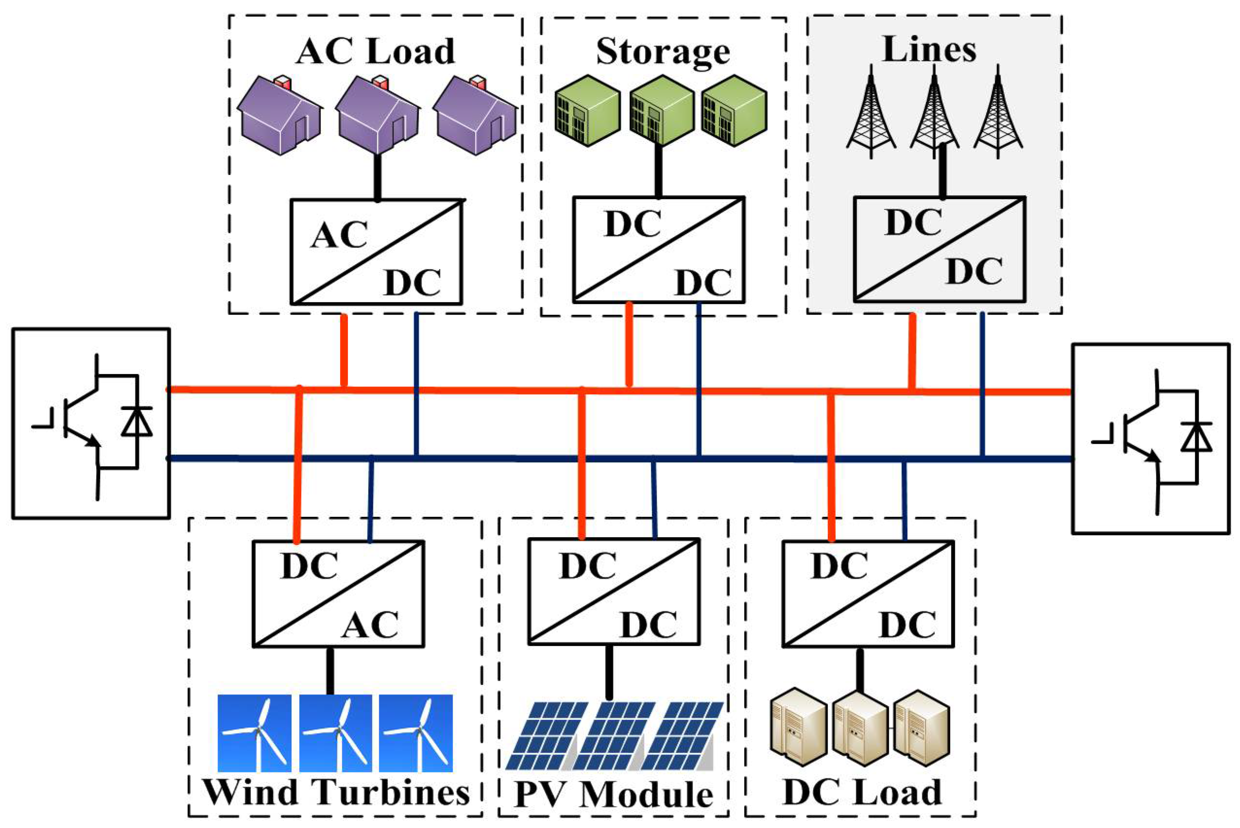
Figure 2.
Ring structure of a multi-terminal DC microgrid.

Figure 3.
Equivalent circuit of voltage source converter (VSC) during a pole-to-pole fault.

Figure 4.
Four successive stages of transient response to pole-to-pole faults: (a) Stage 1: Capacitor discharges through the line with diodes off. (b) Stage 2: Capacitor discharges through the line with diodes on. (c) Stage 3: Inductor discharges through the line with diodes on. (d) Stage 4: Grid current feeds the DC link through the diodes.

Figure 5.
Fault characteristics for voltage source converter (VSC) during a pole-to-pole fault.

Figure 6.
Voltage source converter (VSC)-based DC microgrid system.

Figure 7.
The voltage of inductor for forward faults for CB1 in the multi-terminal system, taking a pole-to-pole fault as an example: f1 on line 12 and f5 on line 24. The DC faults i2 and i5 suggest the fault current through local sensors at CB1.
Figure 7.
The voltage of inductor for forward faults for CB1 in the multi-terminal system, taking a pole-to-pole fault as an example: f1 on line 12 and f5 on line 24. The DC faults i2 and i5 suggest the fault current through local sensors at CB1.

Figure 8.
The voltage of inductor for the backward fault f3 for CB1 in the multi-terminal system; i3 suggests the fault current through local sensors at CB1.
Figure 8.
The voltage of inductor for the backward fault f3 for CB1 in the multi-terminal system; i3 suggests the fault current through local sensors at CB1.

Figure 9.
Influence of fault distance and initial current on the angle.

Figure 10.
Features of DC voltage of positive and negative poles during different fault types: (a) Positive-pole-to-ground fault; (b) Negative-pole-to-ground fault; (c) Pole-to-pole fault.
Figure 10.
Features of DC voltage of positive and negative poles during different fault types: (a) Positive-pole-to-ground fault; (b) Negative-pole-to-ground fault; (c) Pole-to-pole fault.


Figure 11.
The flowchart of the proposed single-ended DC fault protection scheme.

Figure 12.
The DC current of pole-to-pole faults at different distances.

Figure 13.
The DC inductor voltage of pole-to-pole faults at different distances.

Figure 14.
Simulation results for the influence of signal noise: (a) Positive-pole-to-ground (PG) fault; (b) Negative-pole-to-ground (NG) fault; (c) Pole-to-pole (PP) fault.
Figure 14.
Simulation results for the influence of signal noise: (a) Positive-pole-to-ground (PG) fault; (b) Negative-pole-to-ground (NG) fault; (c) Pole-to-pole (PP) fault.

Figure 15.
Simulation results for the influence of sampling frequency: (a) Positive-pole-to-ground (PG) fault; (b) Negative-pole-to-ground (NG) fault; (c) Pole-to-pole (PP) fault.
Figure 15.
Simulation results for the influence of sampling frequency: (a) Positive-pole-to-ground (PG) fault; (b) Negative-pole-to-ground (NG) fault; (c) Pole-to-pole (PP) fault.


Table 1.
Simulation results of faulted pole selection for forward faults.
| Fault Type | x/m | Rfault/Ω | KU | Fault Type | x/m | Rfault/Ω | KU |
|---|---|---|---|---|---|---|---|
| Internal PG fault 1 | 100 | 0.1 | 29.8425 | Internal PP fault 1 | 100 | 0.1 | 1.0492 |
| 1 | 18.6964 | 1 | 1.0772 | ||||
| 500 | 0.1 | 17.9425 | 500 | 0.1 | 1.0375 | ||
| 1 | 12.1508 | 1 | 1.0575 | ||||
| 900 | 0.1 | 13.6224 | 900 | 0.1 | 1.0541 | ||
| 1 | 10.0290 | 1 | 1.0887 | ||||
| Internal NG fault 1 | 100 | 0.1 | 0.0177 | External PP fault | 100 | 0.1 | 1.0832 |
| 1 | 0.0434 | 1 | 1.1373 | ||||
| 500 | 0.1 | 0.0131 | 500 | 0.1 | 1.0816 | ||
| 1 | 0.0421 | 1 | 1.1258 | ||||
| 900 | 0.1 | 0.0220 | 900 | 0.1 | 1.1132 | ||
| 1 | 0.0608 | 1 | 1.1763 |
1 PG (NG) fault: positive (negative)-pole-to-ground fault; PP fault: pole-to-pole fault.
Table 2.
Simulation results of internal fault identification.
| Fault Type | x/m | Rfault/Ω | Results |
|---|---|---|---|
| Internal PG, NG, and PP faults | 100 | 0.1 | Internal |
| 1 | Internal | ||
| 500 | 0.1 | Internal | |
| 1 | Internal | ||
| 900 | 0.1 | Internal | |
| 1 | Internal | ||
| External PG, NG, and PP faults | 100 | 0.1 | External |
| 1 | External | ||
| 500 | 0.1 | External | |
| 1 | External | ||
| 900 | 0.1 | External | |
| 1 | External |
1 PG (NG) fault: positive (negative)-pole-to-ground fault; PP fault: pole-to-pole fault.
© 2018 by the authors. Licensee MDPI, Basel, Switzerland. This article is an open access article distributed under the terms and conditions of the Creative Commons Attribution (CC BY) license (http://creativecommons.org/licenses/by/4.0/).
Share and Cite
MDPI and ACS Style
Lv, C.; Zheng, X.; Tai, N.; Chen, S. Single-Ended Protection Scheme for VSC-Based DC Microgrid Lines. Energies 2018, 11, 1440. https://doi.org/10.3390/en11061440
AMA Style
Lv C, Zheng X, Tai N, Chen S. Single-Ended Protection Scheme for VSC-Based DC Microgrid Lines. Energies. 2018; 11(6):1440. https://doi.org/10.3390/en11061440
Chicago/Turabian StyleLv, Cheng, Xiaodong Zheng, Nengling Tai, and Shi Chen. 2018. "Single-Ended Protection Scheme for VSC-Based DC Microgrid Lines" Energies 11, no. 6: 1440. https://doi.org/10.3390/en11061440
Note that from the first issue of 2016, this journal uses article numbers instead of page numbers. See further details here.