Article

Photovoltaic Integrated Shunt Active Power Filter with Simpler ADALINE Algorithm for Current Harmonic Extraction

by
Muhammad Ammirrul Atiqi Mohd Zainuri
1,*,
Mohd Amran Mohd Radzi
2,
Azura Che Soh
2,
Norman Mariun
2,
Nasrudin Abd Rahim
3,
Jiashen Teh
1 and
Ching-Ming Lai
4
1
School of Electrical and Electronic Engineering, Engineering Campus, Universiti Sains Malaysia, 14300 Nibong Tebal, Pulau Pinang, Malaysia
2
Department of Electrical and Electronic Engineering, Faculty of Engineering, Universiti Putra Malaysia, 43400 UPM Serdang, Selangor, Malaysia
3
UM Power Energy Dedicated Advanced Centre, Wisma R&D, Universiti Malaya, 59990 Kuala Lumpur, Malaysia
4
Department of Vehicle Engineering, National Taipei University of Technology, No. 1, Sec. 3, Chung-Hsiao E. Road, Taipei 106, Taiwan
*
Author to whom correspondence should be addressed.
Energies 2018, 11(5), 1152; https://doi.org/10.3390/en11051152
Submission received: 2 April 2018 / Revised: 29 April 2018 / Accepted: 1 May 2018 / Published: 4 May 2018
(This article belongs to the Special Issue Power Electronics in DC-Microgrid Systems)

Abstract

:
This manuscript presents a significant work in improving the current harmonics extraction algorithm and indirectly improving the injection current produced by a single-phase Photovoltaic Shunt Active Power Filter (PV SAPF). Improvement to the existing adaptive linear neuron (ADALINE) technique has been carried out, leading to the formation of a simpler ADALINE; it is expected to perform as fast as the current harmonics extraction algorithm. Further analysis on the DC link capacitor control algorithm, called “self-charging with step size error cancellation”, was also done to inspect the performance of the algorithm in a single-phase photovoltaic shunt active power filter system. Both algorithms, configured in single-phase PV SAPF, were simulated in MATLAB/Simulink (R2012b). A laboratory prototype was developed, and the algorithms were computed on a TMS320F28335 Digital Signal Processing (DSP) board for hardware implementation purposes. From the acquired results, the simpler ADALINE algorithm has effectively performed with lower total harmonic Distortion (THD) and outstanding compensation. The established algorithm of self-charging with step size error cancellation works well with single-phase PV SAPF and has shown less overshoot, a fast response time, and minimal energy losses.

1. Introduction

The power quality in a power system is the extensive range of electromagnetic phenomena that describe current and voltage at given locations and times in the system [1]. A supply system has its own frequency that it works on. The integer multiples of this frequency are frequencies where harmonic (sinusoidal voltages or currents) power quality issues arise [2,3]. Typically, the nonlinear load operations of power electronic devices are the cause of current harmonics. Another cause is when the supply network is injected with applications that are added in latter stages. The participation of multiple energy source systems with the inclusion of a photovoltaic (PV) grid-connected system in the power system gives rise to these problems [4,5]. Excessive neutral currents, equipment overheating, motor vibration, and capacitor blowing are among the consequences of current harmonics [6]. Current harmonics can be compensated for by using the shunt active power filter (SAPF), which is a very capable tool compared with a passive filter. This is mainly due to its ability to handle multiple harmonics simultaneously [7].
Since photovoltaic (PV) energy is free to harvest, inexhaustible, and much cleaner, it is one of the most renowned renewable energy sources [8]. The integration of renewable energy sources such as PV with SAPF is a possible avenue of exploration in current research works. This integration provides significant advantages by having an alternative energy source rather than depending on the energy source from the supply grid [9,10]. However, as PV entirely depends on the availability of irradiance from the sun, SAPF may operate with possible dynamic changes in injection current. Therefore, the injection current must be controlled suitably with a specific end goal to ensure the effectiveness of the SAPF to compensate for current harmonics. To control the injection current, as further explained in the next sections, at least three algorithms are actively participating, which include DC voltage, current harmonics extraction, and maximum power point tracking (MPPT) control algorithms. In this work specifically, a current harmonics extraction algorithm is proposed for further improvements.
There are three groups into which the current algorithms of harmonics extraction can be classified. They include artificial intelligence, time domain, and frequency domain techniques [11,12]. The frequency domain is always associated with the computation of Fourier coefficients and time delay in sampling, which causes all algorithms in this domain to face difficulties in real-time applications especially with dynamically varying loads [13]. The time domain basically has better performance in terms of convergence speed compared with the frequency domain [11]. However, it remains doubtful as there are possible sings of existing flickers and noise caused by the conversion of the coordinates from the input signals [11,12]. The artificial neural network (ANN) is one of the techniques of artificial intelligence. To mitigate harmonic components, it can correctly approximate or extract time-varying fundamental components in terms of the phase angle and magnitude [14,15]. Among the various ANN architectures, because of its ability to perform current harmonics extraction simply and well, and because it only consists of a single linear system, Widrow–Hoff (W-H) adaptive linear neuron (ADALINE) is preferable over others. However, the learning time of the algorithm is altered because it needs to learn multiple harmonic components; this is a weakness [16,17]. By adding a learning rate in the updating algorithm, an improvement (Modified Widrow–Hoff (W-H) ADALINE) is made to the algorithm’s extraction of the fundamental component [18,19]. However, further improvements need to be made because of the unnecessary characteristics that still exist within the algorithm. They do not act as the basic requirement of extracting current harmonics in the power system. These unnecessary characteristics affect the performance of the algorithm because of the slow learning rate and possible large size of the average square error [20]. These two factors are due to the learning factor of the updating algorithm and the cosine component that may affect the response time of the algorithm. As a consequence, there is still the existence of lag compensation [18]. This algorithm performs with total harmonic distortion (THD) below 5%, accompanied by a response time of 40 ms [18]. The updating algorithm of the Modified W-H ADALINE uses Weight (W) as its learning factor.
The DC link capacitor voltage control algorithm also plays a crucial part in producing a proper injection current for PV SAPF. The main purpose of the algorithm is to control the voltage of the DC link capacitor. The DC link capacitor functions as a bridge between PV and SAPF. The DC link capacitor voltage, if unstable, will affect the overall injection current of the PV SAPF itself. The desired DC link voltage and instantaneous voltage can be changed directly to control the DC link capacitor; this is the conventional method used. Nevertheless, this method does not allow for a desired DC link voltage to be controlled and accurately regulated. As a consequence, voltage that is unclean is produced. Due to the unstable injection current, problems such as high THD and capacitor blowing may occur, which contribute to the major disadvantages [21]. Therefore, self-charging algorithms have shown a significant increase in usage as an alternative option over the conventional algorithm [22]. Principally, the controlling of the charging and discharging of the DC link capacitor uses the energy conversion law [23]. Subsequently, it provides high accuracy and regulated voltage that is clean with the least noise, and fewest ripples and spikes. In its specific operation, the input value of the self-charging algorithm (also known as voltage error) must be obtained from the difference between the instantaneous and desired capacitor voltages. Previously, this voltage error was controlled by such algorithms like proportional–integral (PI) and fuzzy logic techniques. Both techniques were configured to directly process the input value without having a prior understanding of its behavior. Hence, there is no room for such flexibility whether the voltage error changes or not—it still has to be controlled and processed. The possibility of failure may occur when the operation of the self-charging algorithm later deals with a varied parameter and nonlinearity. Unfortunately, previous studies on self-charging algorithms for the most part took into account only steady-state operation [24]. No further analysis has been done on dynamic operation [25,26]. An indirect approach incorporated with fuzzy logic control techniques was introduced [27], called “Self-charging with step size error cancellation”. This indirect approach produces better performance with low overshoot and undershoot (within 0.5–1 V) and fast response time (about 0.5 s), but it is only applicable for shunt active power filter systems and no further testing was done for PV SAPF, especially under various irradiance levels (dynamic operations).
Therefore, this paper presents a significant work in improving the current harmonics extraction algorithm and indirectly improving the injection current produced by a single-phase PV SAPF. Improvements to the ADALINE technique are carried out to produce what we call the Simpler ADALINE algorithm. It is expected to perform as a fast current harmonics extraction algorithm. Meanwhile, additional analysis was performed to investigate the performance of the self-charging with step size error cancellation algorithm for a single-phase PV SAPF system under dynamic and steady-state operations. The proposed single-phase PV SAPF is covered in Section 2, while Section 3 covers the proposed current harmonics extraction algorithm used in the PV SAPF. This is followed by an elaboration of the established self-charging algorithm in Section 4. Section 5 and Section 6 discuss the hardware implementation and simulation work, along with the results. This work is concluded in Section 7.

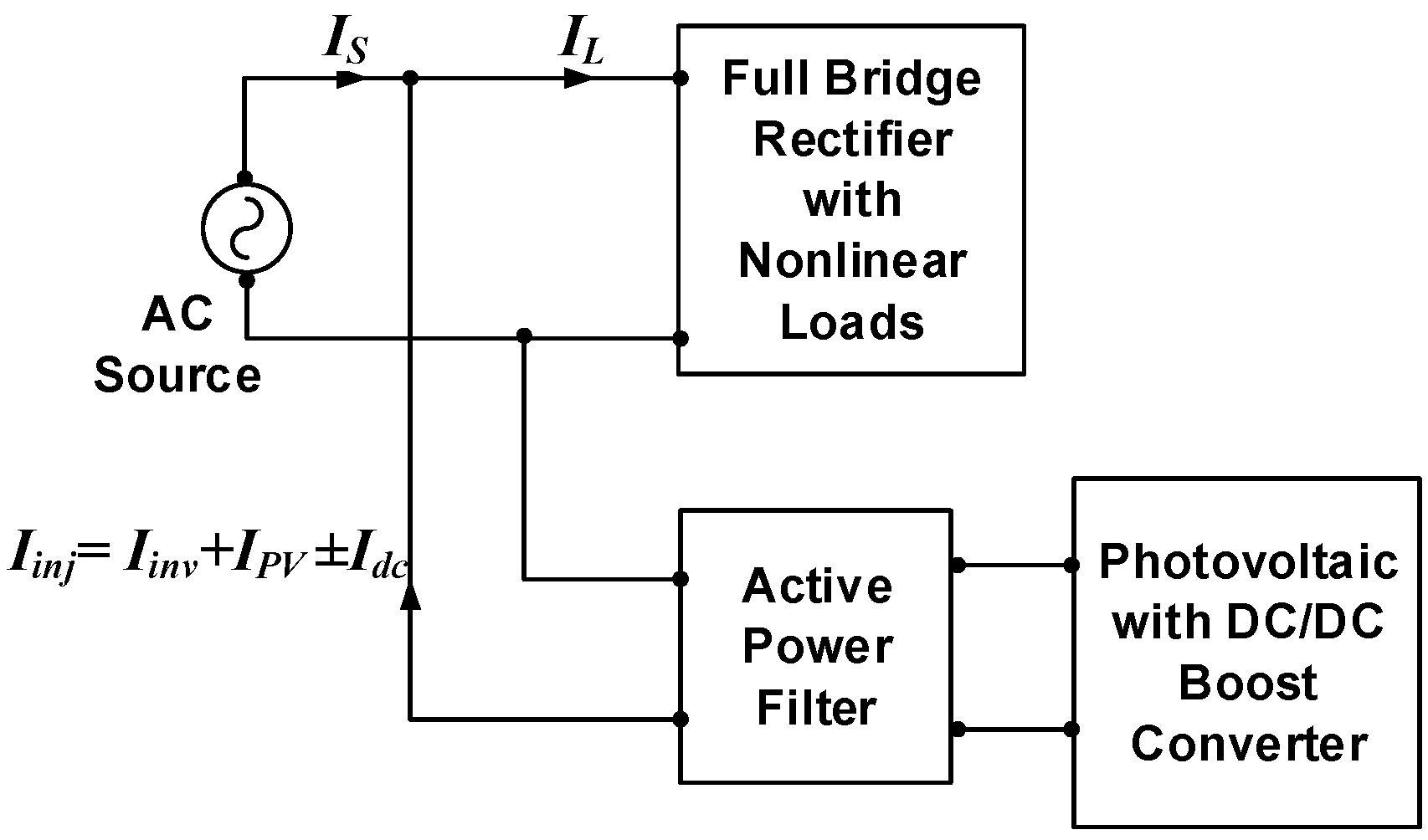
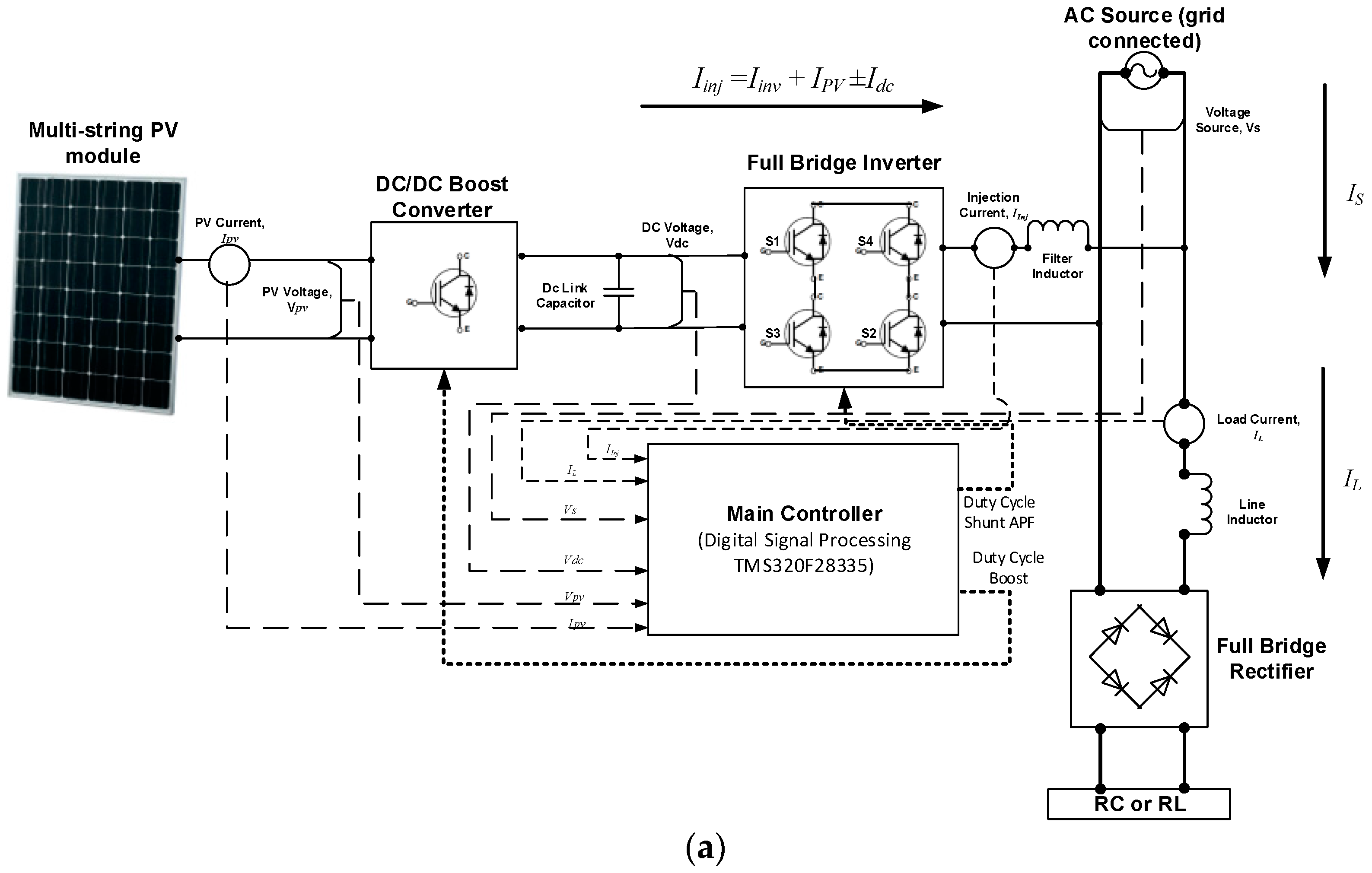
2. Single-Phase Photovoltaic Shunt Active Power Filter

A block diagram is shown in Figure 1 to represent operation of the PV SAPF connected at a point of common coupling of the grid source which supplies power to a nonlinear load.
The nonlinear load operation contains load current IL, which comprises harmonic component IH, within the source current IS. An injection current Iinj is generated after the SAPF is connected; this compensates for the harmonic current, leaving only the fundamental component I1, as shown below.
I S = I L I i n j = I 1 + I H I i n j
With existence of PV, the injection current Iinj will comprise a combination of the capacitor charging current Idc, inverter current Iinv, and PV current IPV.
I i n j = I i n v + I P V ± I d c
For the injection of appropriate current to be accomplished by the SAPF, each current parameter in Equation (2) must be controlled. Hence, we take into consideration the three algorithms. First, the current harmonics extraction algorithm is used to control the inverter current Iinv; second, the maximum power point tracking (MPPT) algorithm is used to control the PV current IPV; third and finally, the DC voltage control algorithm is used to control the capacitor charging current Idc. For the capacitor charging current Idc, there is possibility it is supplied from the grid or the capacitor with both directions. Its value and sign depend on the voltage of the DC link capacitor as when the voltage is overshot, its sign will be positive (discharging) in order to reduce the voltage, and when the voltage is undershot, its sign will be negative (charging) for voltage to increase. The capacitor charging current Idc is equal to zero when the desired voltage is on point.
Figure 2 shows the overall circuit of the single-phase PV SAPF which contains a PV array, DC/DC boost converter, full bridge inverter, DC link capacitor, and its controller. The controller consists of algorithms such as DC link capacitor voltage control, current harmonics extraction, MPPT, current control, and synchronizer. However, as mentioned earlier, this paper focuses on the current harmonics extraction and DC link capacitor voltage control algorithms in order to control the inverter current Iinv and the capacitor charging current Idc, respectively. The Adaptive Perturb and Observe (P&O)–Fuzzy algorithm is implemented as the MPPT algorithm [28], due to the fact that it can perform with fast response time and high accuracy. Proportional–integral (PI) was used as the current control algorithm for controlling the steady-state error of the reference current signal [29]. For this particular research work, the unified ADALINE-based fundamental voltage extraction algorithm is used as the synchronizer [30].

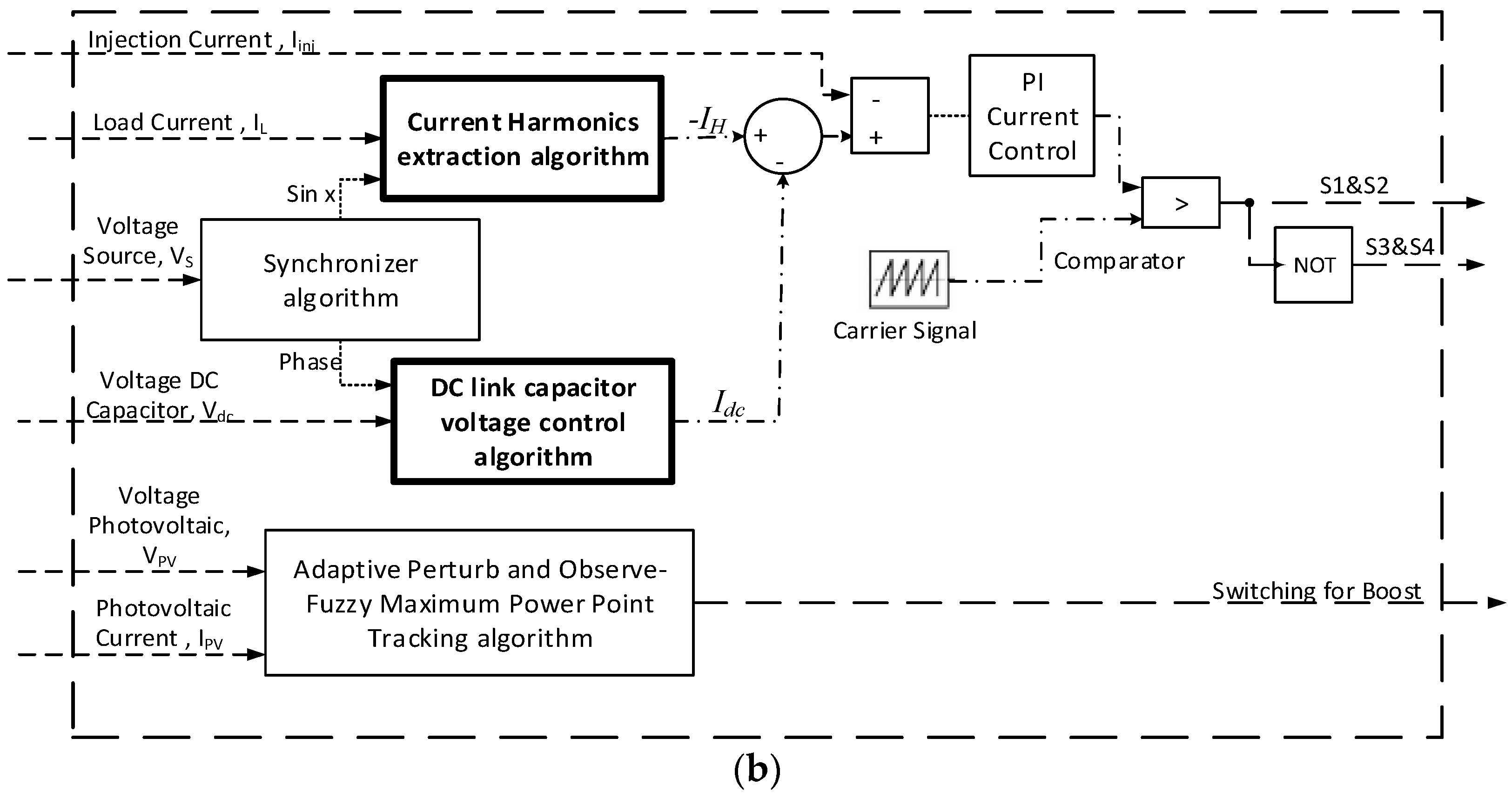
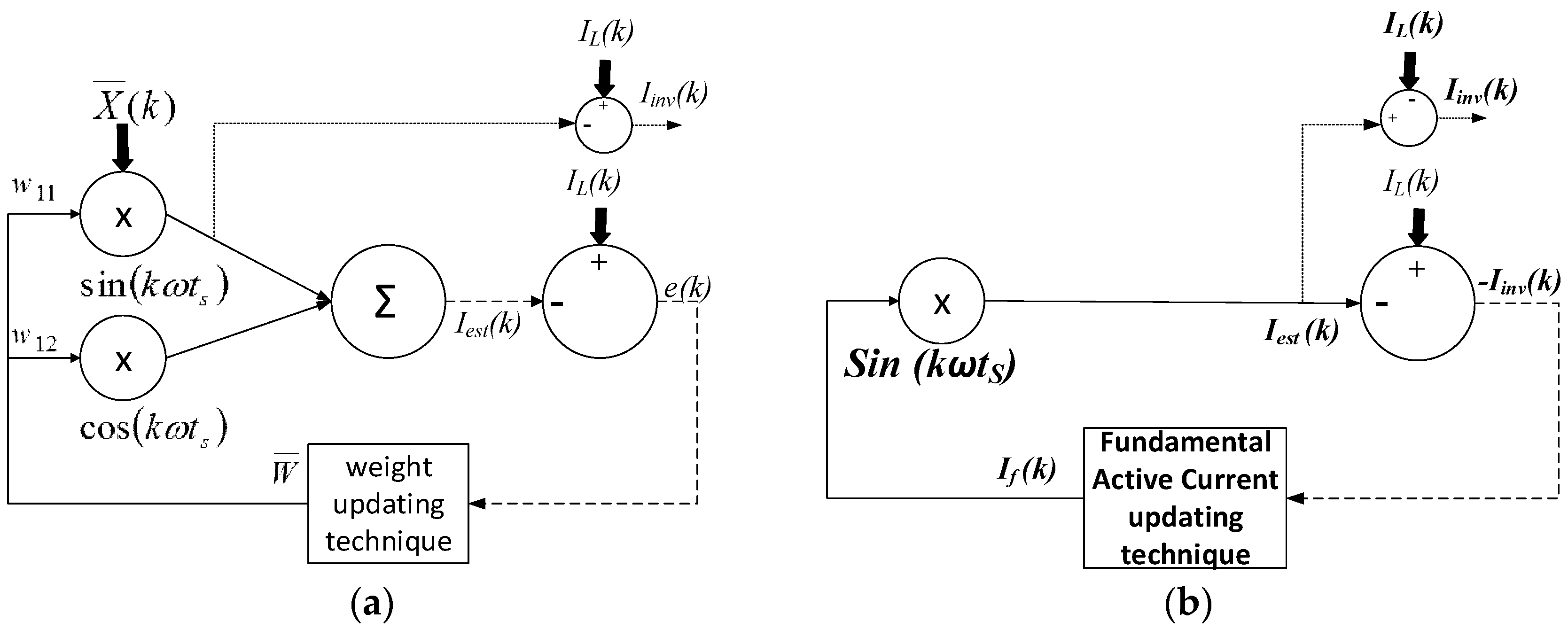
3. Simpler ADALINE-Based Current Harmonics Extraction

In basic principle, the normal ADALINE algorithm estimates harmonic components based on the principle of sine and cosine components that exist in the electrical system for current harmonics extraction. The harmonic components and fundamental component for each sample k and sampling period ts in digital operation with assigned fundamental frequency ω can be depicted by the nonlinear load current IL [18,31,32], or
I L ( k ) = n = 1 , 2 N [ W a n sin ( n k ω t s ) W b n cos ( n k ω t s ) ]
where the order of the harmonic to N maximum is given by n, and amplitudes of the sine and cosine components are given by Wan and Wbn. By rearranging Equation (3) in vector form, the following equations holds:
I L ¯ ( k ) = W ¯ T X ¯ ( k )
where W ¯ T = [ w 11 w 21 …… w a n w b n ] is the weight matrix and X ¯ describes the cosine and sine vector as X ¯ T = [ sin ( k ω t s ) cos ( k ω t s ) …… sin ( n k ω t s ) cos ( n k ω t s ) ] . To train W ¯ T to be equivalent to the value of nonlinear load current IL, the algorithm is used. The Widrow–Hoff (W-H) method is used because of its updating algorithm that is the main feature of this extraction algorithm [18]. Weight is used as the learning factor in the Widrow–Hoff (W-H) method. However, to reduce complexity of the normal ADALINE, the Modified W-H ADALINE has been proposed. This only uses the first order of the harmonic component as opposed to the n-many harmonic components in the normal Windrow–Hoff ADALINE, as depicted in Figure 3a [18]. It is independent of number of harmonic orders due to the need to only update the two weights of the fundamental component. However, a learning rate α is introduced as a by-product because of the large average square error e produced in this method [18]. Therefore, the weight updating equation becomes
W ¯ ( k + 1 ) = W ¯ ( k ) + α e ( k ) Y ¯ ( k ) Y ¯ T ( k ) Y ¯ ( k )
where W ¯ T = [ w 11 w 21 ] , Y ¯ = [ sin ( k ω t s ) cos ( k ω t s ) ] , and α is the learning rate. The harmonics current IH can be produced as below [19]:
I H ( k ) = I L ( k ) W sin ( k ω t s )
where W sin(kωts) represents the fundamental sine component multiplied by its weight factor W. To reimburse harmonic distortion, the inverter current Iinv is used; this is inversely proportional to the harmonic current IH. Although it is capable of reducing THD below 5%, The Modified W-H ADALINE algorithm still has disadvantages that may lead to the current harmonics extraction being slowed. Extracting current harmonics has basic requirements that it has to fulfil and the unnecessary characteristics that it has do not represent them. Hence, it can be further simplified and improved. The first simplification is made by discarding the periodic signal cosine component. According to the symmetrical theory of AC power systems, the odd function of periodic signals is of the sine component only. This is because odd functions are inversely symmetrical about the y axis. In Equation (3), when Wbn is made equal to zero (Wbn = 0), odd functions are of the sine components only. The sum of elements is automatically removed when the cosine component is removed. As a result, the average square error e is removed in large magnitudes, making this the second improvement.
Changing the learning factor of the updating algorithm is the third improvement. The functionality of SAPF is not clearly shown by the weight factor W in Equation (5). Before it is multiplied by the sine component, this learning factor represents the active fundamental current peak value. In simpler terms, it is renamed as the fundamental active current If, or
I f = W
The last improvement is made by replacing the average square error e, as shown in Figure 3a, with the negative inverter current −Iinv as further elaborated below.
e ( k ) = I L ( k ) I e s t ( k ) I i n v ( k ) = [ I L ( k ) I e s t ( k ) ] e ( k ) = I i n v ( k )
A better representation can be seen where the negative inverter current −Iinv is the actual value used later (by removing its negative sign) for the amount of current to be injected by the SAPF. A new updating technique called the Fundamental Active Current (FAC) updating technique is formed by the average square error to the negative inverter current and weight learning factor to the fundamental active current If, or
I f ( k + 1 ) = I f ( k ) α I i n v ( k ) sin ( k ω t s )
Figure 3b shows the last form of the simpler ADALINE algorithm. The new harmonic current equation is
I H ( k ) = I L ( k ) I f s i n ( k ω t s
By referring to Figure 3b and Equation (10), the active current is generated, depicted by If sin(kωts). It is generated by multiplying If with the unity sine function.

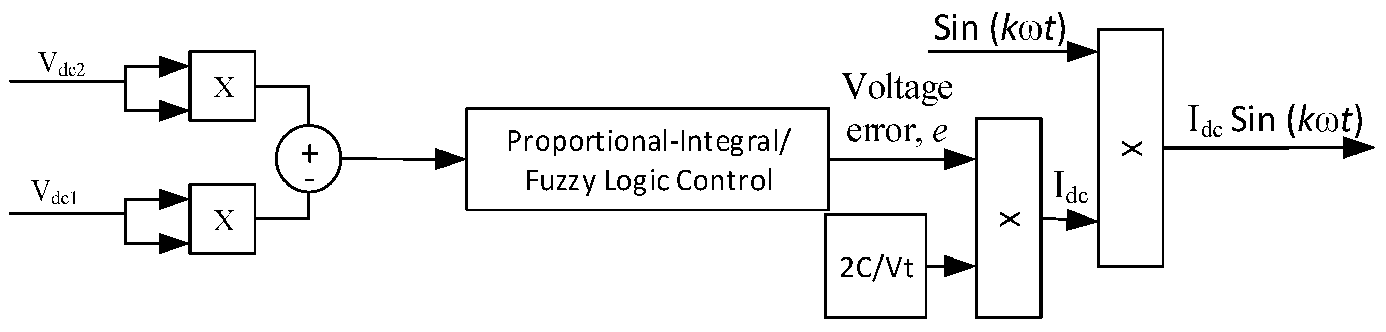
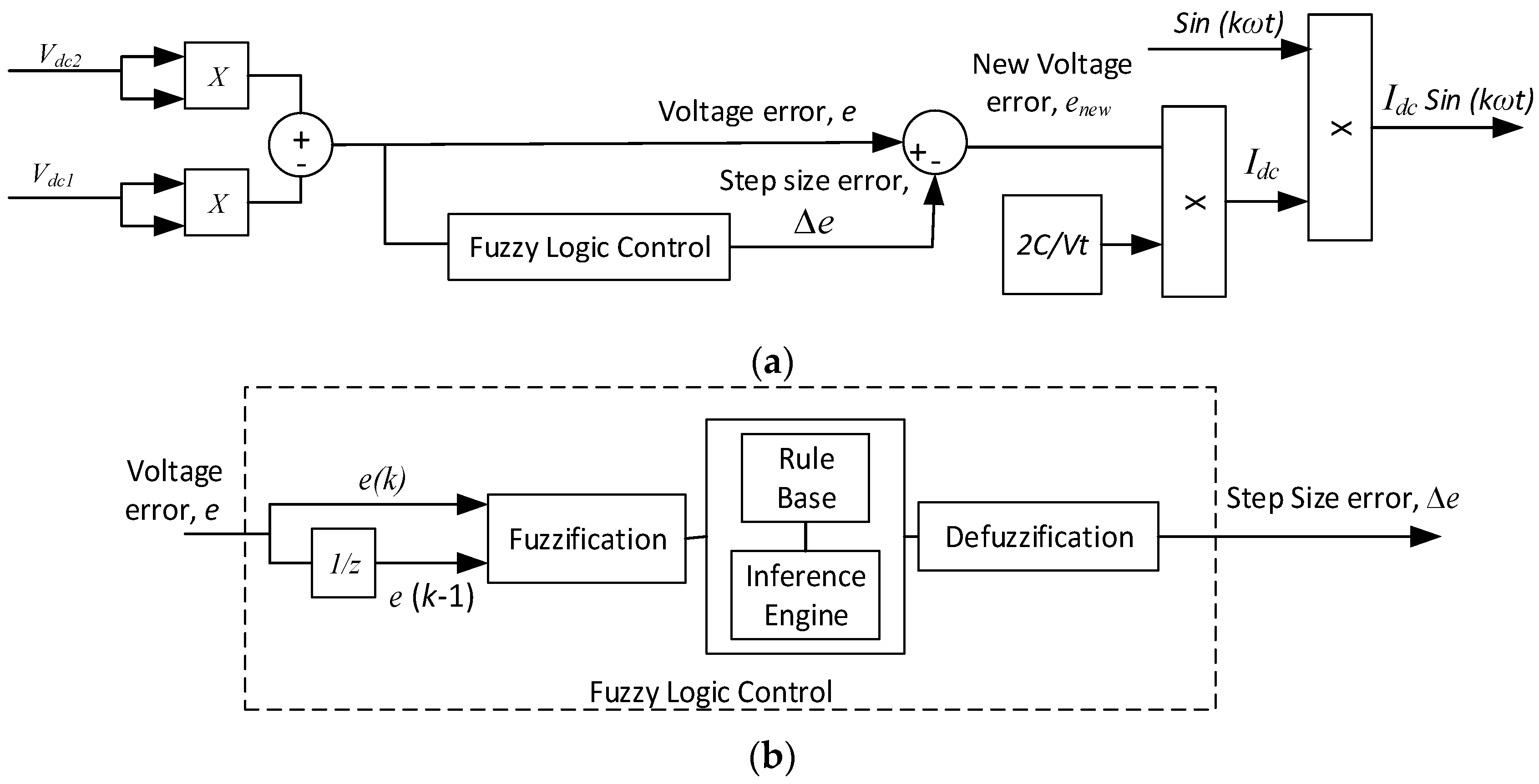
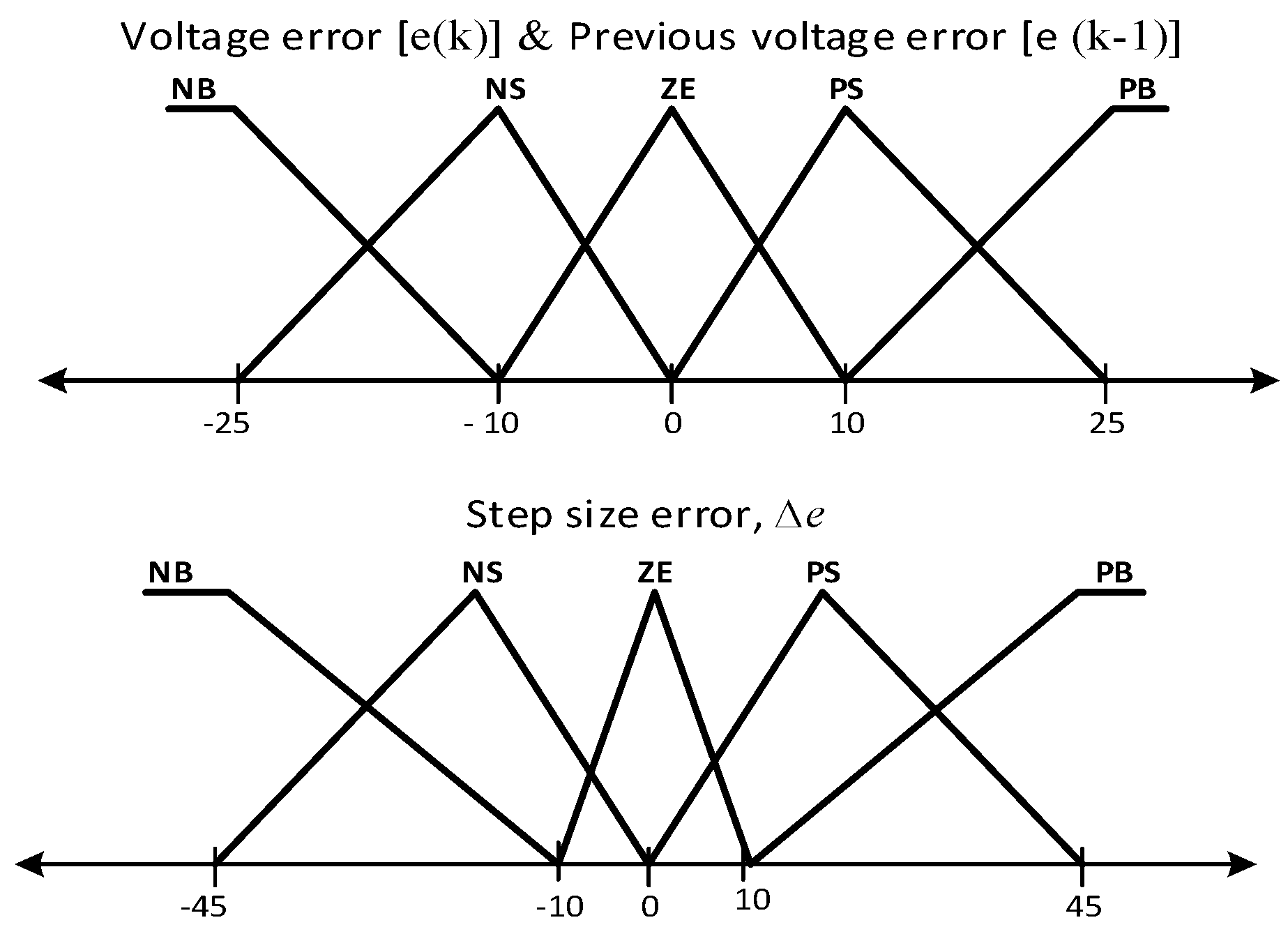
4. Self-Charging with Step Size Error Cancellation Algorithm

In principle, the DC link capacitor voltage should be maintained at the desired set point so that the injection current Iinj is properly generated for compensating harmonics. Therefore, the charging capacitor current Idc is an important factor to be controlled as such change to it may affect the performance of the DC link capacitor. Interestingly, Idc may also affect the performance of the PV array in supplying IPV, besides the existing role carried out by the MPPT algorithm. Considering an analysis of the circuit’s connection between the DC link capacitor and the inverter as shown in Figure 1, the effective amount of IPV injected to the grid depends on the condition of Idc. Therefore, a new parameter named the capacitor–PV current ICPV is introduced, by combining IPV and Idc as follows:
I C P V = I P V ± I d c
Any change to Idc may affect the delivery of IPV, which has to be used for keeping the DC link capacitor voltage at a certain level, rather than to be used for injection. Therefore, it is critical to control Idc, not only to ensure that the voltage of the DC link capacitor is maintained at its desired value, but also to ensure a fast and optimum supply of IPV.
As mentioned, the self-charging algorithm is implemented to control Idc. The charging capacitor current Idc is determined by the energy conversion law mathematical equation in relation to the DC link capacitor. The DC link capacitor voltage always fluctuates from the desired voltage value during the charging process. The energy stored in the DC link capacitor is forced to change as a result. Hence, the self-charging equations [27] are
I d c = 2 C [ ( V d c 2 ) 2 ( V d c 1 ) 2 ] V T
where the DC link capacitor value is given by C, Vdc1 is the desired DC link capacitor voltage, Vdc2 is the instantaneous DC link capacitor voltage, and the period of the supply frequency is given by T. The difference between Vdc1 and Vdc2 can be represented as voltage error e, or
e = ( V d c 2 ) 2 ( V d c 1 ) 2
The change in e gives the impacts in determination of Idc, and, thus, it should be controlled accordingly. To realize control of e, the PI technique has been implemented [19]; with rapid growth of artificial intelligence techniques, especially Fuzzy Logic Control (FLC) [19], better control of voltage error e can be achieved, as shown in Figure 4. However, from the figure it is noticeable that the e is controlled directly, where the FLC has to perform and act accordingly based on whatever its value (including zero). Thus, the capability of the self-charging algorithm is still limited, especially for dynamic operation.
Therefore, to address dynamic operations, modifications and improvements have been made to the direct control approach by arranging it to be an indirect approach, as shown in Figure 5. This indirect control in the self-charging algorithm introduced a new parameter which was named step size error ∆e. It is now part of the existing voltage error e to form a new voltage error enew [27], or
e n e w = e + Δ e e n e w = [ ( V d c 2 ) 2 ( V d c 1 ) 2 ] + Δ e
The new voltage error enew provides an appropriate value to minimize such drastic changes due to change of the capacitor’s voltage. Thus, the charging current Idc [27] becomes
I d c = 2 C [ [ ( V d c 2 ) 2 ( V d c 1 ) 2 ] + Δ e ] V T
The self-charging algorithm is supposed to be able to react smoothly. This is done by giving the algorithm adaptability to abort any change of the voltage error e with respect to overshoot and undershoot. There will be no unnecessary task to perform since the algorithm provides another route to mitigate the voltage error. Even though this approach is considered stable with good undershoot and overshoot, and with fast response time, this approach was only tested with normal shunt active power filter and no further testing and analysis was done for the single-phase PV SAPF system. The FLC membership functions are shown in Figure 6.

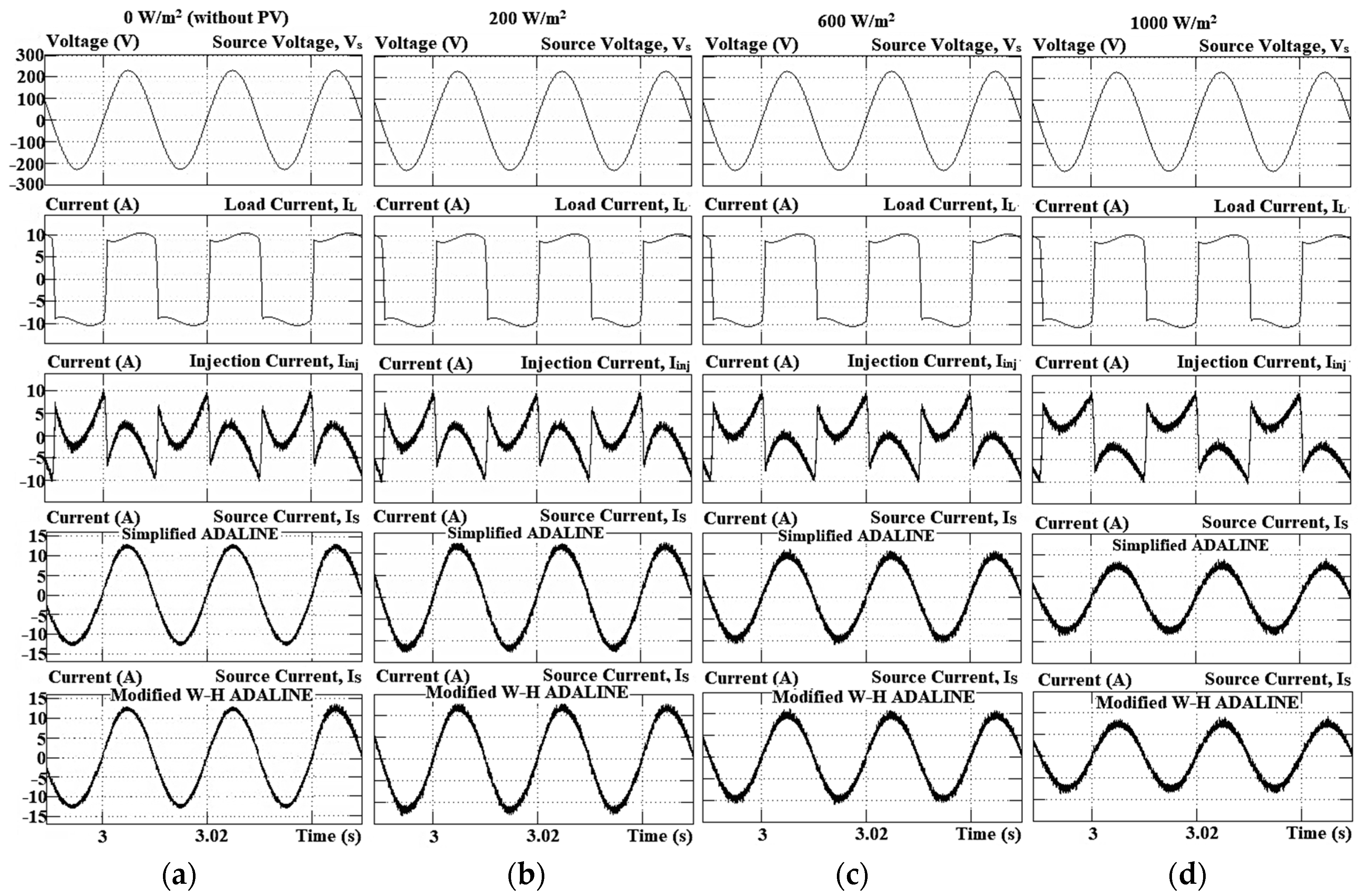
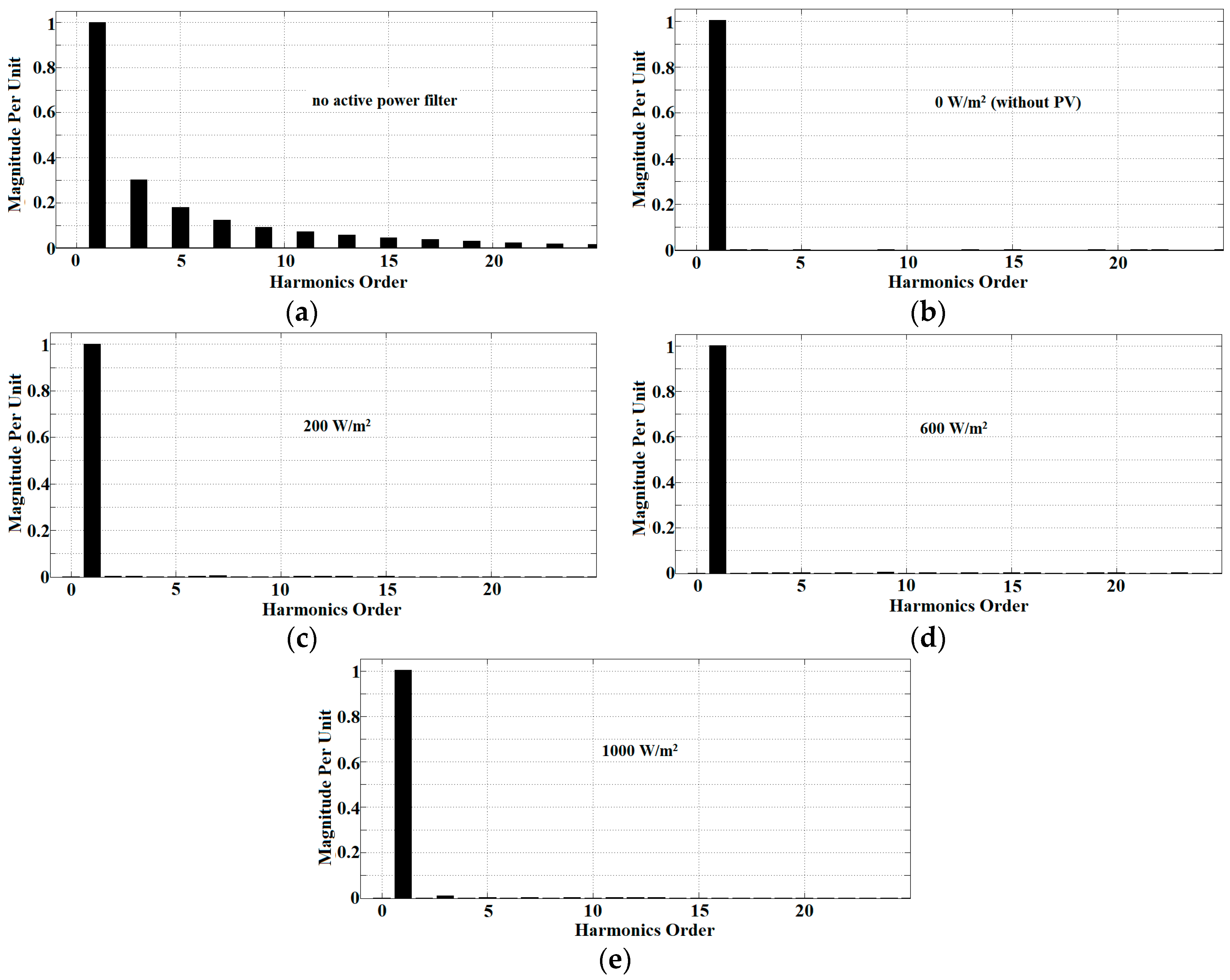
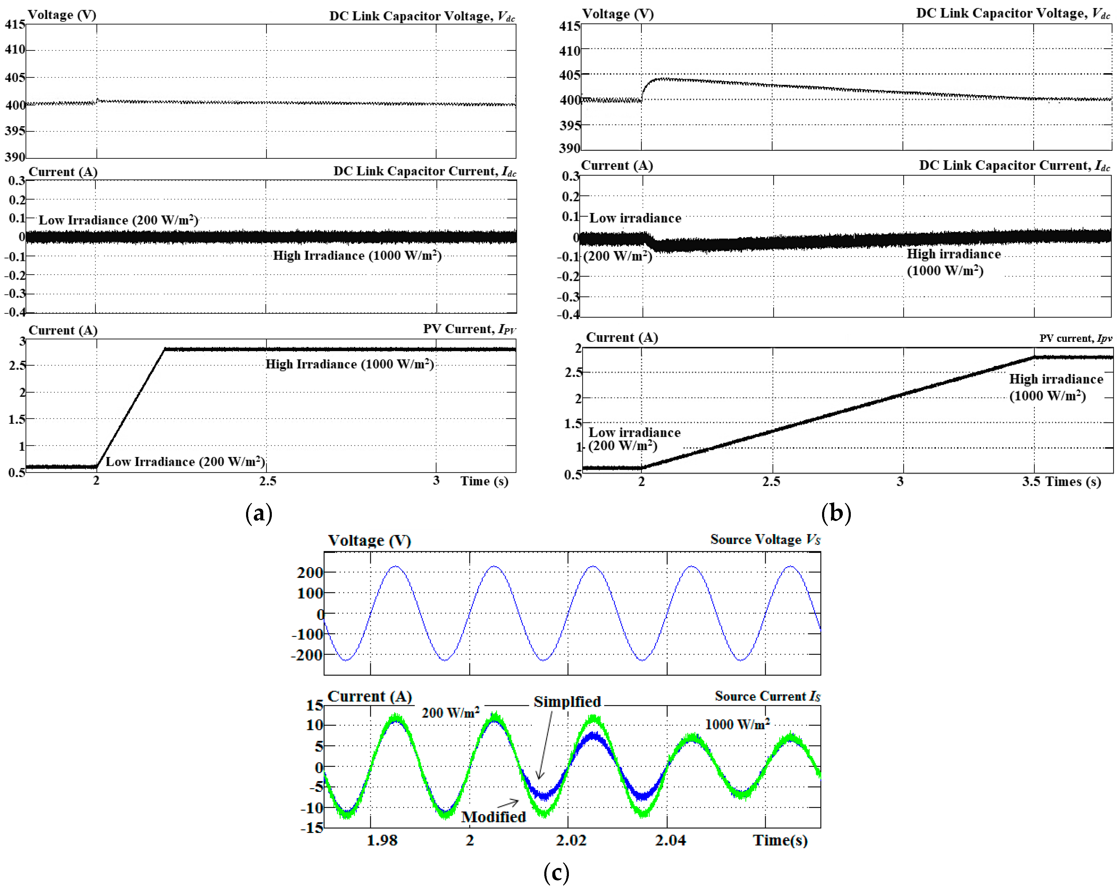
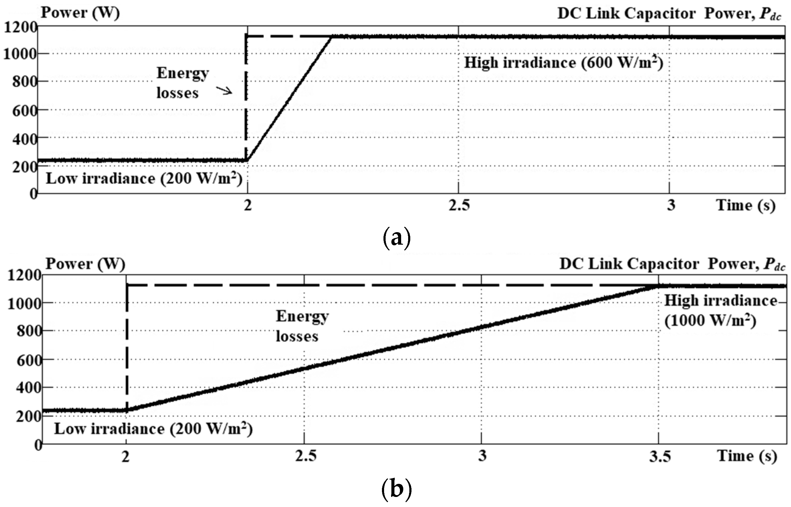
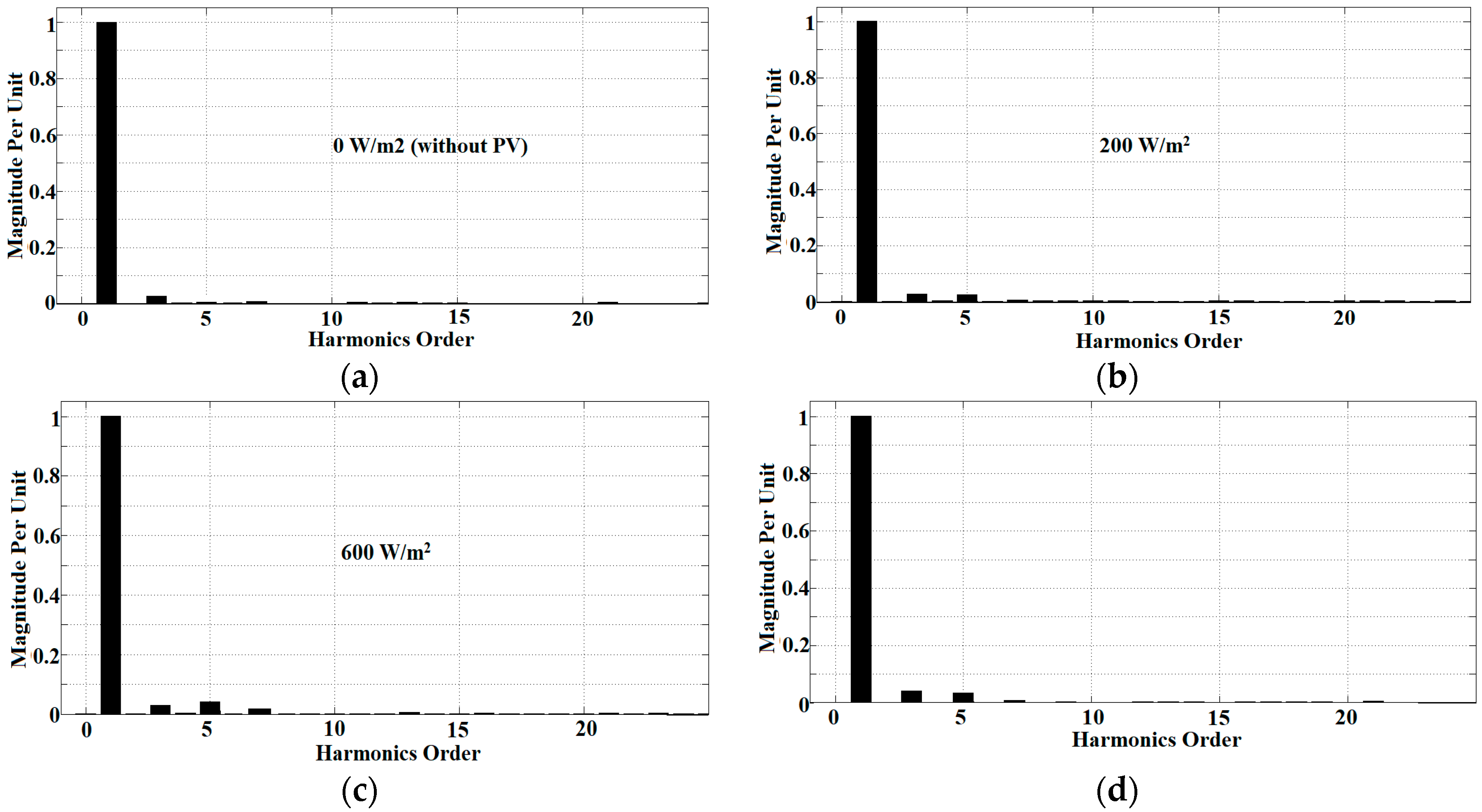
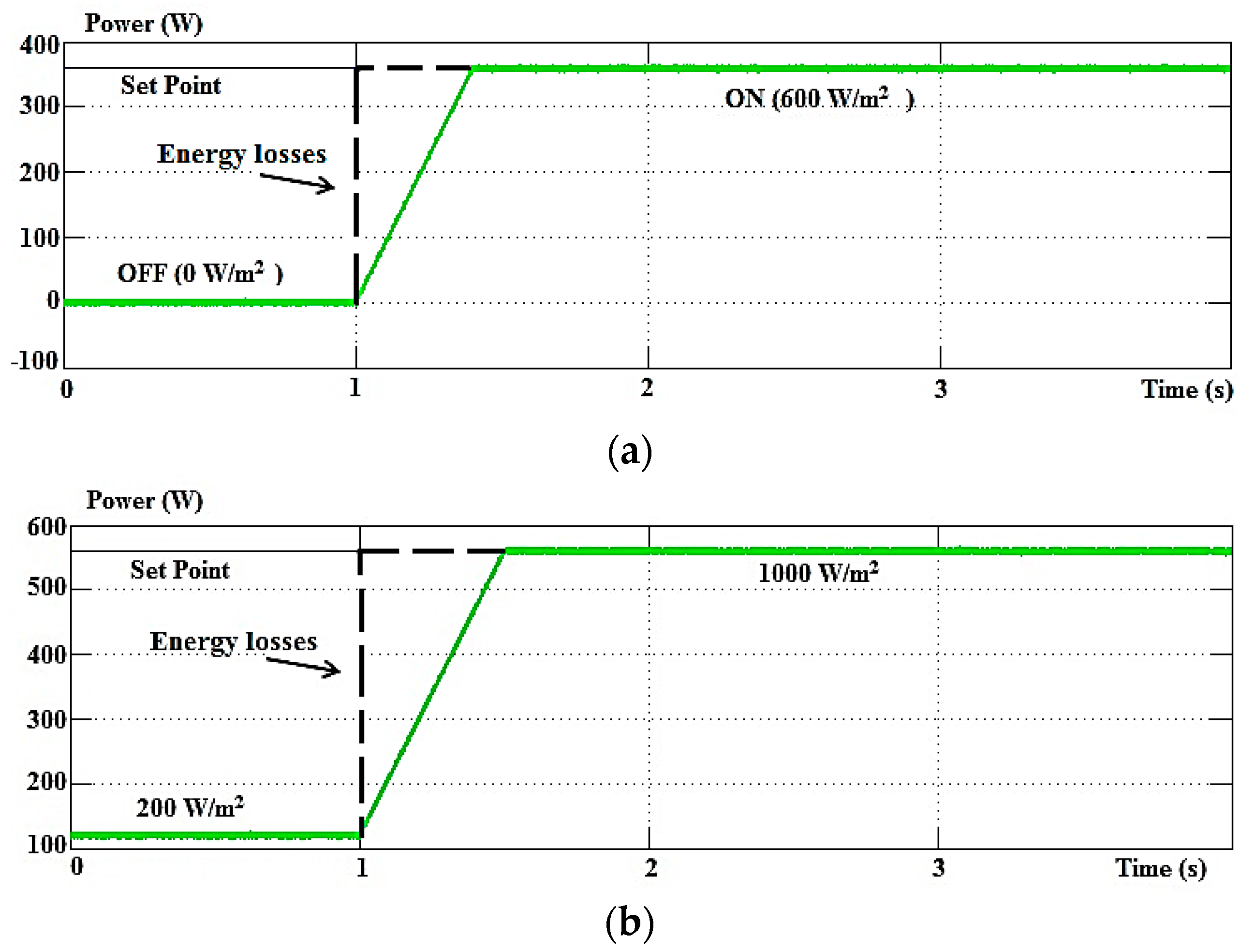
5. Simulation Results

Matlab-Simulink was used to carry out the simulation works. The proposed single-phase PV SAPF was designed and connected with the test bed made up of a nonlinear load and supply grid source. The nonlinear load was developed using an H-bridge rectifier (240 mH inductor and 20 Ω resistor connected in series). Matlab-Simulink was used to implement all the algorithms in Figure 2 together with the proposed single-phase PV SAPF including both proposed algorithms. The simulation work was carried out under dynamic operations to evaluate both algorithms, which covers penetration of PV through off–on operation and change of irradiance from low to high. The PV irradiances were set at about 200 W/m2 (low irradiance), 600 W/m2 (medium irradiance), and 1000 W/m2 (high irradiance). For comprehensive evaluation, performance of the Simpler ADALINE algorithm in reducing THD level was evaluated with the Modified W-H ADALINE algorithm, by fixing the self-charging with step size error cancellation algorithm. In addition, the performance of the self-charging with step size error cancellation algorithm was compared with that of the Direct Fuzzy-based Self-charging algorithm by fixing the simpler ADALINE algorithm. Among the major parameters which were evaluated, besides THD, were overshoot, undershoot, response time, and energy losses. The simulation sampling time was set at about 6.67 µs, while the learning rate of 0.0001 was configured for both proposed and existing algorithms of current harmonics extraction. The duty cycle to boost up the PV voltage to 400 Vdc was set to 0.46. The PV module used was a SHARP NT-180UI (Sharp Electronics Corporation, Huntington Beach, CA, USA) its characteristics are as shown in Table 1. Table 2 shows the main parameters and components used in this work. The configuration of the proposed PV SAPF is based on a voltage source inverter (VSI) which is considered as a conventional inductor-based converter. According to Middlebrook’s extra element theorem [33], to avoid instability, the input impedance of the converter should be much higher than the output impedance of the filter. For the PV SAPF configuration, the switching frequency was set at high frequency—around 20 kHz. The inductive element inside the PV SAPF increases the input impedance for the high switching frequency; therefore, Middlebrook’s condition is verified and the filter does not affect the stability of the proposed PV SAPF.
The simulation outcomes of PV SAPF with different irradiances (including without PV) using both Simpler ADALINE and Modified W-H ADALINE current harmonics extraction algorithms are shown in Figure 7. It covers source current Is, injection current Iinj, voltage Vs, and load current IL for the nonlinear load. Figure 8 shows the simulation results of harmonic spectra for different irradiances (including without PV) for the Simpler ADALINE algorithm. The simulation results of harmonic spectra for the Modified W-H ADALINE algorithm are shown in Figure 9. From Figure 7, Figure 8 and Figure 9, the source current Is is properly compensated for by both current harmonics extraction algorithms. Specifically, for THD, with irradiance of 0 W/m2, the values are 1.48% and 2.12% for Simpler ADALINE and Modified W-H ADALINE algorithms, respectively. At irradiance of 200 W/m2, the THDs are 1.62% and 2.25% for the Simpler ADALINE and Modified W-H ADALINE algorithms. After irradiance is increased to 600 W/m2, the THD recorded using Simpler ADALINE is 1.93%, while for Modified W-H ADALINE, it is around 2.57%. Lastly, at irradiance of 1000 W/m2, the Simpler ADALINE algorithm gives a THD of about 2.28% and Modified W-H ADALINE algorithm gives a THD of about 2.85%.
Both algorithms give THD values below the 5% benchmark as per the IEEE Standard 519-2014 [1]. According to the findings, there is a slight increase in the THD values when the irradiance of the PV is increased, which subsequently increases the PV source current IPV. The source current Is is decreased with the increase of IPV where the load is depending more on power from the PV. Another point to take note of from the findings is during the operation of the normal SAPF, when PV is in the off condition and there should be no additional active power flow to the grid. Only when the PV is in the on condition will additional active power flow to the grid, affecting the injection and source currents. In addition, according to the previous works on SAPF, operation of the normal SAPF compensates only the reactive component, which means it only has the effect of removing harmonics from the grid [34,35]. Therefore, it is confirmed that PV is the main source of producing active power. In comparing both algorithms, Simpler ADALINE clearly shows much better performance over the Modified W-H ADALINE. The significant reduction of THD values shows that the performance of the SAPF is better with the algorithm that is proposed, with or without PV connectivity. Meanwhile, the power factor is improved from 0.89 to almost unity, which directly confirms the effectiveness of the proposed current harmonics extraction algorithm to perform power correction, too.
In regard to the evaluation of DC link capacitor voltage control, dynamic operation of off–on between PV and SAPF was implemented. This is done by considering the level of irradiance to be set at 600 W/m2, as it is considered as medium irradiance in the Malaysia climate [36]. The performances of both DC link capacitor voltage control algorithms and both harmonic extraction algorithms during off–on operation between PV and SAPF are shown in Figure 10. Consideration is given to evaluate both current harmonics extraction algorithms which were simulated together with the DC link capacitor voltage control algorithm. The self-charging with step size error cancellation algorithm performs at a much lower overshoot (0.5 V) and fast response time (0.1 s), as compared to the direct control where it has high overshoot (4.5 V) with slow response time (1.5 s). Meanwhile, both current harmonics extraction algorithms respond well during off–on dynamic operation, but Simpler ADALINE performs with a much better response time of only 15 ms, as opposed to the Modified W-H ADALINE algorithm which needs 40 ms to respond.
Another dynamic operation focuses on the change of irradiance from low to high levels. Figure 11 shows the obtained results. The self-charging with step size error cancellation algorithm produces much better regulated DC link capacitor voltage with a low overshoot of 1 V and fast response time of 0.2 s compared to the direct control approach with an overshoot and response time of 4 V and 1.6 s, respectively. This is almost similar to the case during off–on dynamic operation. At the same time, the Simpler ADALINE also has a response time of about 15 ms, performing faster than the Modified W-H ADALINE with 40 ms. Further analyses to be explored are energy losses during dynamic operations of off–on between PV and SAPF and change of irradiance. Good DC link capacitor voltage control should result in minimal energy losses to the SAPF, especially during integration of PV and SAPF.
Figure 12 and Figure 13 show clearly the energy losses resulting from operation on the DC link capacitor in dynamic operations. During the period of dynamic operation, energy losses on the DC link capacitor Eloss-Cdc can be calculated as below:
E l o s s C d c = t 1 t 2 P d c d t
where Pdc is the steady-state power of the DC link capacitor that should be obtained after change, t1 is the starting time of change, and t2 is the end time of change before achieving steady state. However, considering that the change is linear, the calculation of energy can be performed as follows:
E l o s s C d c = P d c × ( t 2 t 1 ) 2
By referring to Figure 12 and Figure 13, operation of self-charging with step size error cancellation causes lower energy losses as compared to the direct control approach. For off–on operation, the proposed self-charging algorithm only causes energy losses of 36 J, whereas the direct control causes loses up to 540 J. Meanwhile for change of irradiance, the self-charging with step size error cancellation algorithm only causes losses of 112 J; for the direct control, it is 896 J. The results obtained clearly show the capability of the self-charging with step size error cancellation algorithm to significantly minimize the energy losses of the DC link capacitor. Table 3 presents THDs obtained from the simulation results of both current harmonics extraction algorithms with different irradiances and Table 4 shows overall performances of both DC link capacitor control algorithms for both dynamic operations.

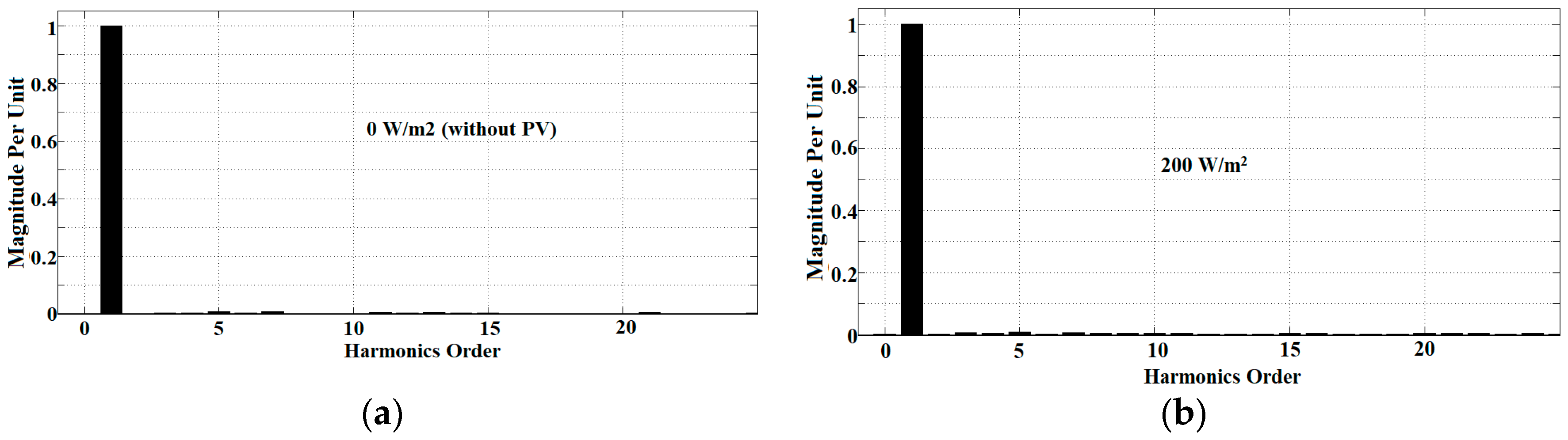
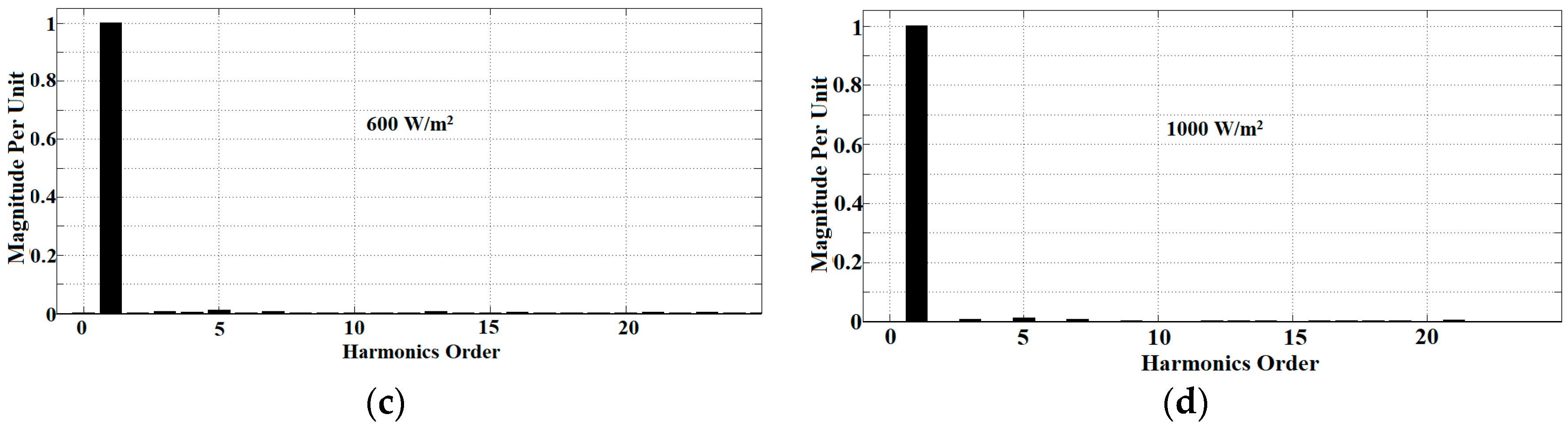
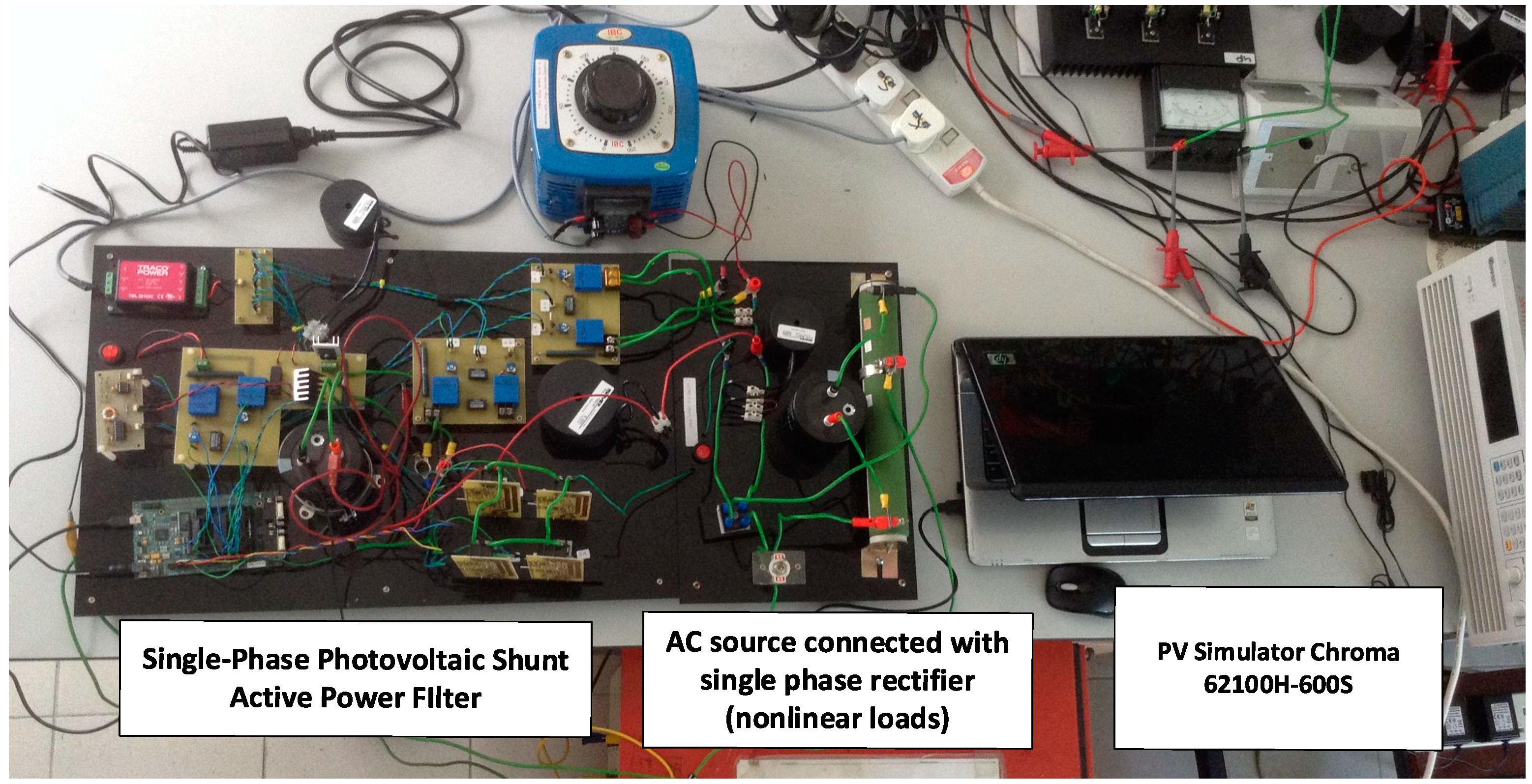
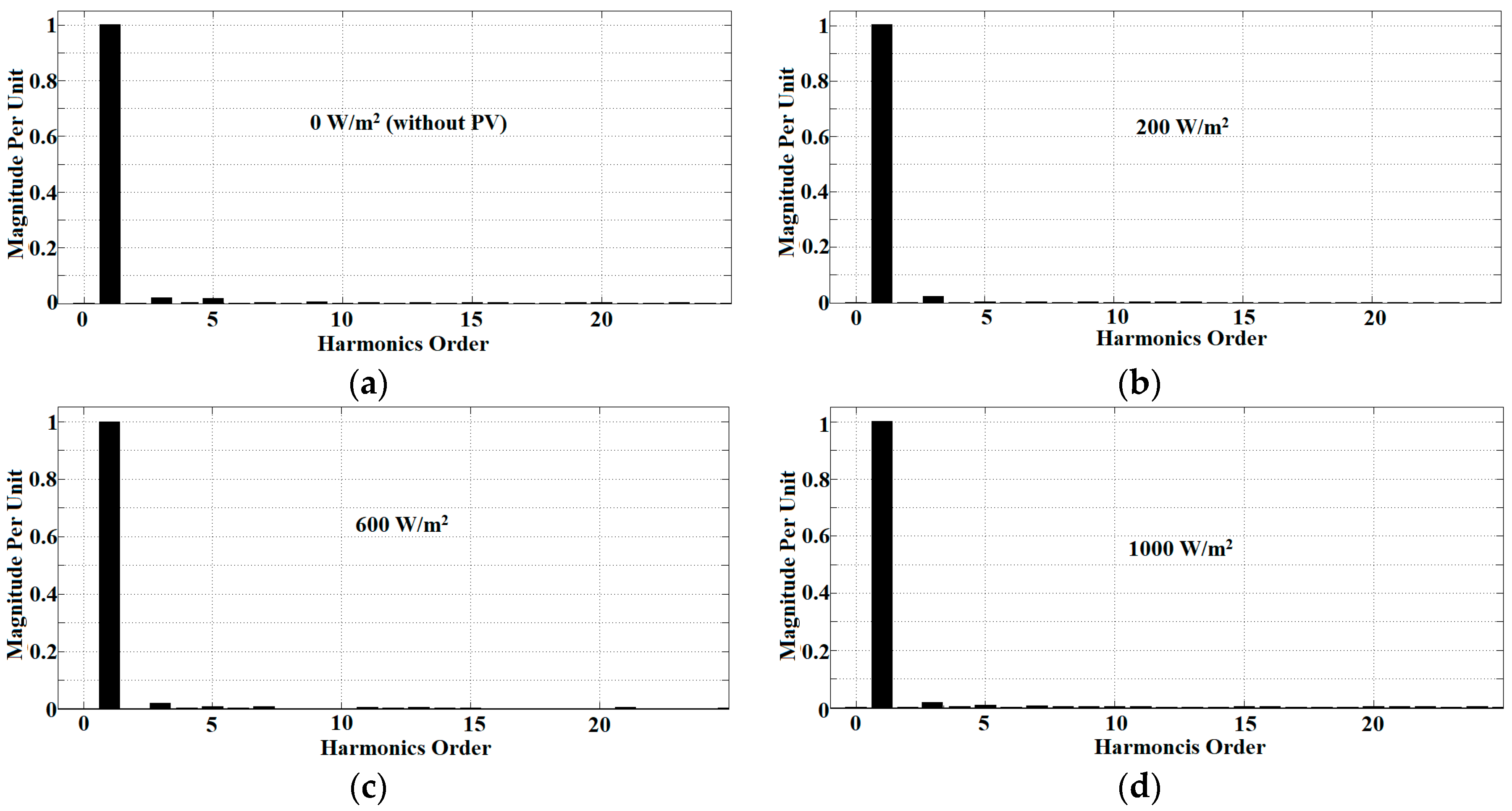
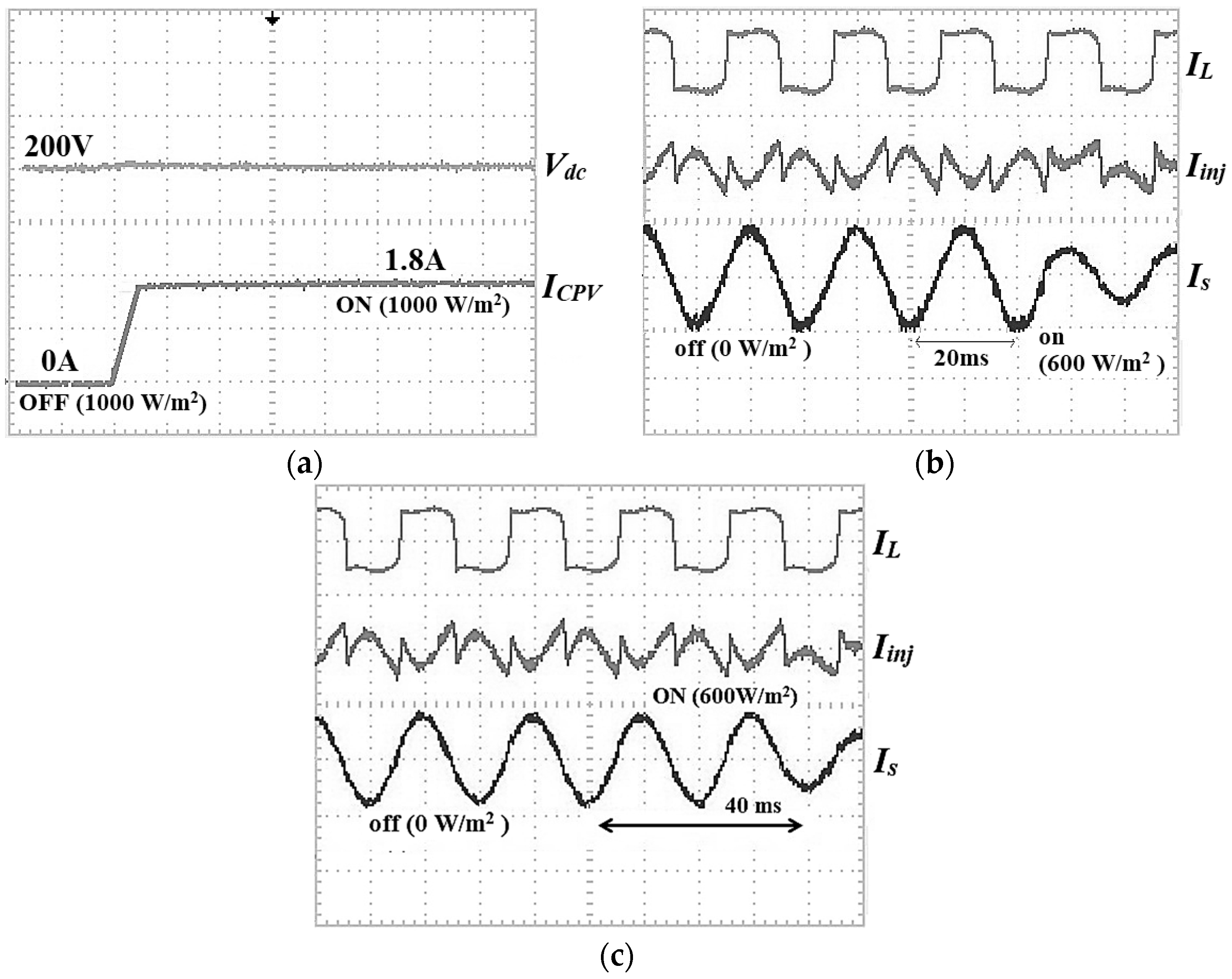
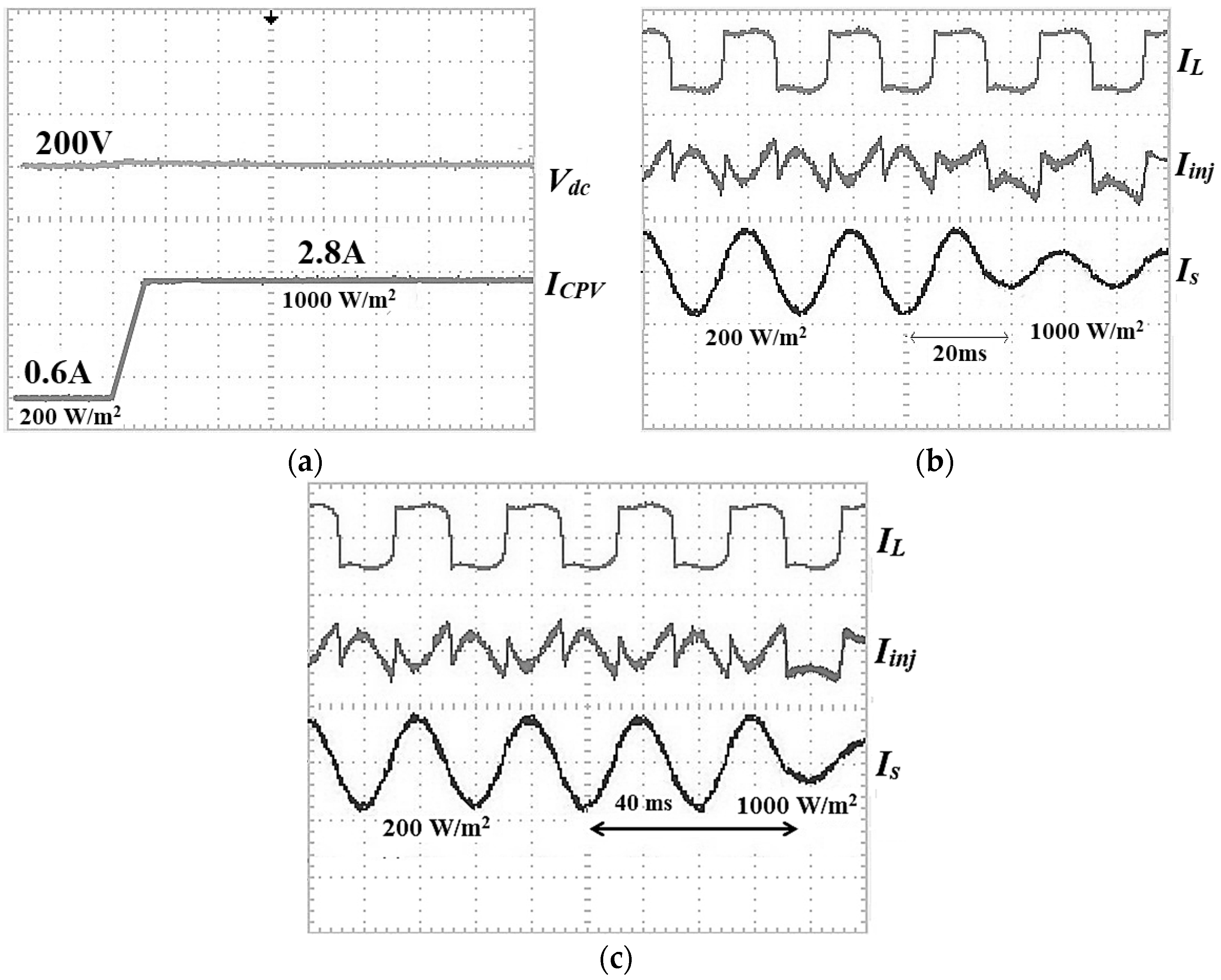
6. Experimental Results

An experimental prototype was developed as in Figure 14 to evaluate the projected algorithms practically (in real time). A model in Matlab-Simulink was used to develop the single-phase PV SAPF. The operated power rating of the PV SAPF is about 536 W with a DC link capacitor of 4400 µF and output filter inductor of 5 mH. The IGBT IHW15N120R3 with maximum operating current of 15 A and maximum operating voltage of 1200 V was selected. For this experimental purpose, using a variable transformer, the supply source voltage was configured to 100 Vac. Hence, the voltage was put to 200 Vdc, which is the desired voltage of the DC link capacitor. To execute all the control strategies for the single-phase PV SAPF, the DSP TMS320F28335 board was programmed and configured. These strategies include the current harmonics extraction, current control, DC link capacitor voltage control, MPPT, and synchronizer. As in the simulation for dynamic operations, the proposed Simpler ADALINE was compared with the established Modified Widrow–Hoff ADALINE algorithm by using the self-charging with step size error cancellation algorithm as the DC link capacitor voltage control algorithm. All the algorithms were evaluated to validate their performance practically in real-time applications. All the measured waveforms were taken by using an oscilloscope Tektronix TBS1000 (Tektronix, Inc., Beaverton, OR, USA) with 4 channels, 150 MHz bandwidth, and 1 GS/s sample rate. The PV simulator Chroma 62100H-600S (Chroma Ate Inc., Kuei-Shan Hsiang, Taoyuan, Taiwan) was the main PV source used for this experiment. It has a voltage range of 0–1.5 kV with output power up to 15 kW.
The experimental outcomes obtained by using the Simpler ADALINE algorithm are shown in Figure 15. It includes the source voltage Vs, injection current Iinj, load current IL, and source current Is, for different irradiance levels. The outcomes of harmonic spectra with different irradiances (including without PV) for the Simpler ADALINE algorithm are shown in Figure 16 while Figure 17 shows the results of harmonic spectra for the Modified W-H ADALINE algorithm. Figure 18 shows the experimental results of the self-charging with step size error cancellation algorithm with Simpler ADALINE and Modified Widrow-Hoff ADALINE current harmonics extraction algorithms with off–on operation between PV and SAPF. The results of the self-charging with step size error cancellation algorithm with Simpler ADALINE and Modified Widrow–Hoff ADALINE current harmonics extraction algorithm under low to high irradiance operation of PV are shown in Figure 19. Figure 20 shows the energy losses using the self-charging with step size error cancellation DC link capacitor voltage control algorithm for both dynamic operations.
Figure 15, Figure 16 and Figure 17 show that the THDs obtained are 2.3% for irradiance at 0 W/m2, 2.54% at 200 W/m2, 2.8% at 600 W/m2, and lastly 3.2% at 1000 W/m2. The THDs obtained are almost the same as in the simulation work. The proposed current harmonics extraction algorithm is proven to work well to compensate current harmonics to below than 5% THD under any level of PV irradiance. The power factor has been improved from 0.86 to almost unity. This confirms the productiveness of the proposed algorithm to accomplish power factor corrections as well. By referring to Figure 18 and Figure 19, the self-charging with step size error cancellation algorithm performs with low overshoot (0.5 V) for off–on operation between PV and SAPF, and only 1 V for change of irradiance. The self-charging with step size error cancellation algorithm also produces a fast response time within 0.3 s for the off–on operation between PV and SAPF, and within 0.4 s for the change of irradiance. The same also applies to the proposed harmonic extraction algorithm where for both dynamic operations, the Simpler ADALINE algorithm achieved a fast response time of only 20 ms. The established Modified Widrow–Hoff ADALINE algorithm produces a slow response time of about 40 ms—about 20 ms slower than the proposed algorithm. This really shows that the proposed current harmonic extraction algorithm performs well with good THD values under various irradiances and fast response times under various dynamic operations. Referring to Figure 20, under the first dynamic operation which involves off–on operation between the PV and SAPF, the self-charging with step size error cancellation algorithm produces low energy losses of only 54 J. The self-charging with step size error cancellation algorithm produces an energy loss of around 112 J for the second dynamic operation of the adjustment of irradiance between low and high irradiance levels.

7. Conclusions

A new algorithm in relation to current harmonics extraction for SAPF integrated with a PV source has been presented in this paper. The new current harmonics extraction algorithm is a simpler and improved version of the established Modified Widrow–Hoff ADALINE algorithm and is called the Simpler ADALINE algorithm. The improvements were made by removing the unnecessary features inside the existing algorithm such as cosine factor and sum of elements and by rearranging the weight factor. The Simpler ADALINE algorithm shows fast and accurate extraction. Analysis of the self-charging with step size error cancellation algorithm’s further performance towards a single-phase PV SAPF system has also been presented. Evaluations in terms of dynamic operations have been made to verify the performances of both algorithms. The analysis under steady-state operation has extensively been used in the past. Hence, dynamic operations such as the change of irradiance level and off–on operation between PV and SAPF were investigated. These analyses provide the novelty of this work due to the extensive findings and results for further evaluation.
Demonstration of the projected current harmonics extraction algorithm has been successfully accomplished. A comparative evaluation has also been completed with the established algorithm (Modified W-H ADALINE). As for the DC link capacitor voltage control algorithm, the established self-charging with step size error cancellation was successfully demonstrated and was compared with the established Direct Fuzzy-based Self-charging algorithm. The simulation and experimental works confirm the much better performance of the projected current harmonics extraction algorithm over the established algorithms. The Simpler ADALINE algorithm performs with THD values that are low with fast response time and various irradiance levels during both dynamic operations. The self-charging with step size error cancellation algorithm works well for single-phase PV SAPF and was able to have low overshoot accompanying fast response time in dynamic operations. A vast difference was observed during the two dynamic operations where the projected Simpler ADALINE algorithm and the established self-charging with step size error cancellation algorithm were able to control any effects from the change of irradiance level for the PV source and off and on operations between PV and SAPF.

Author Contributions

M.A.A.M.Z. designed and developed the main parts of the research work, including simulation model, experimental set up, and analyses of the obtained results. M.A.A.M.Z. was also mainly responsible for preparing the paper. M.A.M.R., A.C.S., N.M., and N.A.R. contributed in simulation, experimental, and writing parts. J.T. and C.-M.L. also involved in verifying the work and actively contributed to finalize the manuscript.

Acknowledgments

This work is supported by the Putra grant scheme from Universiti Putra Malaysia and key performance index (KPI) grant under the School of Electrical and Electronic Engineering, Universiti Sains Malaysia, Malaysia.

Conflicts of Interest

The authors declare no conflicts of interest.

Nomenclature

ωAngular frequency
αLearning rate
tsSampling period
eAverage square error
e(k)Digital time-varying average square error
ILLoad current
IL(k)Digital time-varying load current
I1Fundamental current
ISSource current
IS(k)Digital time-varying source current
WWeight learning factor
W(k + 1)Matrix of next iteration weight
If(k + 1)Matrix of next iteration fundamental active current
WanAmplitude of the sine component
WbnAmplitude of the cosine component
nHarmonic order
NMaximum harmonic order
Sin (k ωts)Sine function
VdcDC link capacitor voltage
Vdc1Desired DC link capacitor voltage
Vdc2Instantaneous DC link capacitor voltage
VsSource voltage
Y(k)Matrix of sine and cosine function
IHHarmonic current
IH(k)Digital time-varying harmonic current
IfFundamental active current
IinjInjection current
Iest(k)Digital time-varying estimation current
IPVPV current
IinvInverter current
IdcCapacitor charging current
ICPVCapacitor–PV current
EacCharging energy of AC
PReal power
tcCharging time of the capacitor
VrmsRMS value of the supply voltage
Idc,rmsRMS value of the charging capacitor current
VPeak value of the supply voltage
TPeriod
ӨPhase angle
EEnergy differential
eStep size error
enewNew voltage error

References

  1. Institute of Electrical and Electronics Engineers. IEEE Recommended Practice and Requirements for Harmonic Control in Electric Power Systems; IEEE Standard 519; Institute of Electrical and Electronics Engineers: New York, NY, USA, 2014; pp. 1–29. [Google Scholar]
  2. Qasim, M.; Kanjiya, P.; Khadkikar, V. Artificial-neural-network-based phase-locking scheme for active power filters. IEEE Trans. Ind. Electron. 2014, 61, 3857–3866. [Google Scholar] [CrossRef]
  3. Zhou, Y.; Li, H. Analysis and Suppression of Leakage Current in Cascaded Multilevel Inverter Based PV Systems. IEEE Trans. Power Electron. 2014, 29, 5265–5277. [Google Scholar] [CrossRef]
  4. He, G.; Xu, D.; Chen, M. A Novel Control Strategy of Suppressing DC Current Injection to the Grid for Single-Phase PV Inverter. IEEE Trans. Power Electron. 2015, 30, 1266–1274. [Google Scholar] [CrossRef]
  5. Hamidreza, K.; Hamid, A.T. Single-Stage Multistring PV Inverter with an Isolated High-Frequency Link and Soft-Switching Operation. IEEE Trans. Power Electron. 2014, 29, 3919–3929. [Google Scholar]
  6. Hoon, Y.; Mohd Radzi, M.A.; Hassan, M.K.; Mailah, N.F. Control Algorithms of Shunt Active Power Filter for Harmonics Mitigation: A Review. Energies 2017, 10, 2038. [Google Scholar] [CrossRef]
  7. Musa, S.; Radzi, M.A.M.; Hizam, H.; Wahab, N.I.A.; Hoon, Y.; Zainuri, M.A.A.M. Modified Synchronous Reference Frame Based Shunt Active Power Filter with Fuzzy Logic Control Pulse Width Modulation Inverter. Energies 2017, 10, 758. [Google Scholar] [CrossRef]
  8. Faranda, R.; Leva, S. Energy Comparison of MPPT Techniques for PV Systems. WSEAS Trans. Power Syst. 2008, 3, 446–455. [Google Scholar]
  9. Vavilapalli, S.; Padmanaban, S.; Subramaniam, U.; Mihet-Popa, L. Power balancing control for grid energy storage system in photovoltaic applications—Real time digital simulation implementation. Energies 2017, 10, 928. [Google Scholar] [CrossRef]
  10. Barater, D.; Buticchi, G.; Lorenzani, E.; Concari, C. Active Common-Mode Filter for Ground Leakage Current Reduction in Grid-Connected PV Converters Operating with Arbitrary Power Factor. IEEE Trans. Ind. Electron. 2014, 61, 3940–3950. [Google Scholar] [CrossRef]
  11. Dogan, H.; Akkaya, R. A control scheme employing an adaptive hysteresis current controller and an uncomplicated reference current generator for a single-phase shunt active power filter. Turk. J. Electr. Eng. Comput. Sci. 2014, 22, 1085–1097. [Google Scholar] [CrossRef]
  12. Akagi, H.; Kanazawa, Y.; Nabae, A. Instantaneous reactive power compensators comprising switching devices without energy storage components. IEEE Trans. Ind. Appl. 2008, 3, 625–630. [Google Scholar] [CrossRef]
  13. Wang, Y.; Yao, L.; Peng, J.; Wang, Y.; Mao, X. Analysis of Harmonic Current Suppression and Reactive Power Compensation on 125 MVA Motor Generator. IEEE Trans. Plasma Sci. 2012, 40, 705–709. [Google Scholar] [CrossRef]
  14. Tey, L.H.; Soand, P.L.; Hu, Y.C. Improvement of power quality using adaptive shunt filter. IEEE Trans. Power Deliv. 2005, 20, 1558–1568. [Google Scholar] [CrossRef]
  15. Abdul Rahman, N.F.; Mohd Radzi, M.A.; Che Soh, A.; Mariun, N.; Abd Rahim, N. Adaptive Hybrid Fuzzy-Proportional Plus Crisp-Integral Current Control Algorithm for Shunt Active Power Filter Operation. Energies 2016, 9, 737. [Google Scholar] [CrossRef]
  16. Cirrincione, M.; Pucci, M.; Vitale, G. A single-phase DG generation unit with shunt active power filter capability by adaptive neural filtering. IEEE Trans. Ind. Electron. 2008, 55, 2093–2110. [Google Scholar] [CrossRef]
  17. Singh, B.; Verma, V.; Solanki, J. Neural network-based selective compensation of current quality problems in distribution system. IEEE Trans. Ind. Electron. 2007, 54, 53–60. [Google Scholar] [CrossRef]
  18. Radzi, M.A.M.; Rahim, N.A. Neural network and band-less hysteresis approach to control switched capacitor active power filter for reduction of harmonics. IEEE Trans. Ind. Electron. 2009, 54, 1477–1484. [Google Scholar] [CrossRef]
  19. Abdul Rahman, N.F.A.; Radzi, M.A.M.; Mariun, N.; Che Soh, A.; Rahim, N.A. Integration of dual intelligent algorithms in shunt active power filter. In Proceedings of the 2013 IEEE Conference on Clean Energy and Technology (CEAT), Langkawi, Malaysia, 8–20 November 2013; pp. 259–264. [Google Scholar]
  20. Bhattacharya, A.; Chakraborty, C. ADALINE controlled 3-phase 3-wire shunt active power filter with enhanced performance using the capacitor voltage feedback. In Proceedings of the IEEE International Conference on Industrial Technology, Churchill, Victoria, Australia, 10–13 February 2009; pp. 1–6. [Google Scholar]
  21. Mikkili, S.; Panda, A.K. Types-1 and -2 fuzzy logic controllers-based shunt active filter Id-Iq control strategy with different fuzzy membership functions for power quality improvement using RTDS hardware. IET Power Electron. 2013, 6, 818–833. [Google Scholar] [CrossRef]
  22. Farahat, M.A.; Zobah, A. Active Filter for Power Quality Improvement by Artificial Neural Networks Technique. In Proceedings of the 39th International Universities Power Engineering Conference, Bristol, UK, 6–8 September 2004; pp. 878–883. [Google Scholar]
  23. Abdel Aziz, M.M.; Zobaa, A.F.; Hosni, A.A. Neural network controlled shunt active filter for non linear loads. In Proceedings of the 11th International Middle East Power Systems Conference, El-minia, Egypt, 19–21 December 2006; pp. 180–188. [Google Scholar]
  24. Priya, S.M.; Keerthana, K. Regulating Unified Power Quality Conditioner Output Using Kalman Filters. Int. J. Mod. Eng. Res. 2013, 62–73. [Google Scholar]
  25. Khoor, M.S.; Machmoum, M. A low voltage dynamic voltage restorer with self-charging capability. In Proceedings of the European Conference on Power Electronics and Applications, Aalborg, Denmark, 2–5 September 2007; pp. 1–9. [Google Scholar]
  26. Kwan, K.H.; So, P.L.; Chu, Y.C. An Output Regulation-Based Unified Power Quality Conditioner with Kalman Filters. IEEE Trans. Ind. Electron. 2012, 59, 4248–4262. [Google Scholar] [CrossRef]
  27. Zainuri, M.A.A.M.; Radzi, M.A.M.; Soh, A.C.; Rahim, N.A. Development of adaptive perturb and observe-fuzzy control maximum power point tracking for photovoltaic boost dc–dc converter. IET Renew. Power Gener. 2013, 8, 183–194. [Google Scholar] [CrossRef]
  28. Zainuri, M.A.A.M.; Radzi, M.A.M.; Soh, A.C.; Rahim, N.A. Adaptive P&O-fuzzy control MPPT for PV boost dc-dc converter. In Proceedings of the 2012 IEEE International Conference on Power and Energy, Kota Kinabalu, Malaysia, 2–5 December 2012; pp. 524–529. [Google Scholar]
  29. Daniyal, H.; Lam, E.; Borle, L.J.; Iu, H.H. Hysteresis, PI and ramptime current control techniques for APF: An experimental comparison. In Proceedings of the 2011 6th IEEE Conference on Industrial Electronics and Applications (ICIEA), Beijing, China, 21–23 June 2011; pp. 2151–2156. [Google Scholar]
  30. Abdul Rahman, N.F.A.; Radzi, M.A.M.; Mariun, N.; Che Soh, A.; Rahim, N.A. Dual Function of Unified Adaptive Linear Neurons Based Fundamental Component Extraction Algorithm for Shunt Active Power Filter Operation. Int. Rev. Electr. Eng. 2015, 10, 544–552. [Google Scholar] [CrossRef]
  31. Appalanaidu Menda, V.V.; Sankaraprasad, B.; Kalyani, K. Neural network based shunt active filter for harmonic reduction: A technological review. Int. J. Eng. Res. Dev. 2012, 2, 32–41. [Google Scholar]
  32. Vardar, K.; Akpinar, E. Comparing ADALINE and IRPT methods based on shunt active power filters. Eur. Trans. Electr. Power 2011, 21, 924–936. [Google Scholar] [CrossRef]
  33. Saponara, S.; Ciarpi, G.; Groza, V.Z. Design and experimental measurement of EMI reduction techniques for integrated switching DC/DC converters. Can. J. Electr. Comput. Eng. 2017, 40, 116–127. [Google Scholar]
  34. Akagi, H. Active Harmonic Filters. Proc. IEEE 2005, 93, 2128–2141. [Google Scholar] [CrossRef]
  35. Wamane, S.S.; Baviskar, J.R.; Wagh, S.R. A Comparative Study on Compensating Current Generation Algorithms for Shunt Active Filter under Non-linear Load Conditions. Int. J. Sci. Res. Publ. 2013, 3, 1–6. [Google Scholar]
  36. Azhar Ghazali, M.; Abdul Malek, A.R. The Performance of Three Different Solar Panels for Solar Electricity Applying Solar Tracking Device under the Malaysian Climate Condition. Energy Environ. Res. 2012, 2, 235–243. [Google Scholar]
Figure 1. Block diagram of Photovoltaic Shunt Active Power Filter (PV SAPF).
Energies 11 01152 g001
Figure 2. Single-phase PV SAPF: (a) circuit diagram and (b) control strategies.
Energies 11 01152 g002aEnergies 11 01152 g002b
Figure 3. Block diagrams of (a) Modified Widrow–Hoff adaptive linear neuron (ADALINE) and (b) Simpler ADALINE algorithms.
Energies 11 01152 g003
Figure 4. Direct control in self-charging algorithm.
Energies 11 01152 g004
Figure 5. Indirect control in self-charging algorithm: (a) block diagram and (b) details of Fuzzy Logic Control.
Energies 11 01152 g005
Figure 6. Membership functions for change of voltage error, previous voltage error, and step size error.
Energies 11 01152 g006
Figure 7. Simulation results which cover source voltage Vs, load current IL, injection current Iinj, and source current Is using both current harmonics extraction algorithms for (a) 0 W/m2 (without PV), (b) 200 W/m2, (c) 600 W/m2, and (d) 1000 W/m2.
Energies 11 01152 g007
Figure 8. Simulation results of harmonic spectra for inductive load using Simpler ADALINE algorithm with (a) no active power filter and at (b) 0 W/m2 (without PV), (c) 200 W/m2, (d) 600 W/m2, and (e) 1000 W/m2.
Energies 11 01152 g008
Figure 9. Simulation results of harmonic spectra for inductive load using the Modified W-H ADALINE algorithm at (a) 0 W/m2 (without PV), (b) 200 W/m2, (c) 600 W/m2, and (d) 1000 W/m2.
Energies 11 01152 g009aEnergies 11 01152 g009b
Figure 10. Simulation results of DC link capacitor voltage under off–on operation between PV and SAPF by using (a) step size error cancellation and (b) direct control in self-charging algorithms; (c) performance of current harmonics extraction algorithms.
Energies 11 01152 g010
Figure 11. Simulation results of DC link capacitor voltage under low to high irradiance using (a) step size error cancellation and (b) direct control in self-charging algorithms; (c) performance of current harmonics extraction algorithms.
Energies 11 01152 g011
Figure 12. Simulation results of DC link capacitor power under off–on operation between PV and SAPF using (a) step size error cancellation and (b) direct control in self-charging algorithms.
Energies 11 01152 g012
Figure 13. Simulation results of DC link capacitor power under low to high irradiance using (a) step size error cancellation and (b) direct control in self-charging algorithms.
Energies 11 01152 g013
Figure 14. Experimental prototype of single-phase PV SAPF.
Energies 11 01152 g014
Figure 15. Experimental results which cover source voltage Vs (200 A/div), load current IL (5 A/div), injection current Iinj (5 A/div), and source current Is (5 A/div) using the Simpler ADALINE current harmonics extraction algorithm for (a) 0 W/m2, (b) 200 W/m2, (c) 600 W/m2, and (d) 1000 W/m2.
Energies 11 01152 g015
Figure 16. Experimental results of harmonic spectra for inductive load using the Simpler ADALINE algorithm at (a) 0 W/m2 (without PV), (b) 200 W/m2, (c) 600 W/m2, and (d) 1000 W/m2.
Energies 11 01152 g016
Figure 17. Experimental results of harmonics spectra for inductive load using the Modified W-H ADALINE algorithm at (a) 0 W/m2 (without PV), (b) 200 W/m2, (c) 600 W/m2, and (d) 1000 W/m2.
Energies 11 01152 g017
Figure 18. Experimental results of (a) the self-charging with step size error cancellation DC link capacitor voltage control algorithm under off–on operation between PV and SAPF, with (b) Simpler ADALINE and (c) Modified Widrow–Hoff ADALINE current harmonics extraction algorithms covering load current IL (5 A/div), injection current Iinj (5 A/div), and source current Is (5 A/div).
Energies 11 01152 g018
Figure 19. Experimental results of (a) self-charging with step size error cancellation DC link capacitor voltage control algorithm under change of irradiance of PV, with (b) Simpler ADALINE and (c) Modified Widrow–Hoff ADALINE current harmonics extraction algorithms covering load current IL (5 A/div), injection current Iinj (5 A/div), and source current Is (5 A/div).
Energies 11 01152 g019
Figure 20. Energy loss analyses for experimental results of the self-charging with step size error cancellation DC link capacitor voltage control algorithm under (a) off–on and (b) change of irradiance operations.
Energies 11 01152 g020
Table 1. Characteristics of the PV module at 1000 W/m2.
Electrical Characteristics
Maximum power Pmax180 W
Short circuit current Isc 5.60 A
Voltage at maximum power Vmp35.86 V
Current at maximum power Imp5.02 A
Open circuit voltage Voc 44.8 V
Table 2. Parameters and components for PV SAPF.
TypeValue
Switching frequency20 kHz
Injection inductor10 mH
DC link voltage450 Vdc
Boost inductor600 µH
PV voltage35.86 Vdc × 8
Line inductor2 mH
DC link capacitor1600 µF
Voltage source230 Vac
Table 3. Total Harmonics Distortions (THDs) of current harmonics extraction algorithms in simulation work with different irradiances.
Current Harmonics Extraction AlgorithmTotal Harmonics Distortion (%)
0 W/m2200 W/m2600 W/m21000 W/m2
Simpler ADALINE1.481.621.932.28
Modified W-H ADALINE2.122.252.572.85
Table 4. Overall performance of DC link capacitor voltage control algorithms for both dynamic operations.
DC Link Capacitor Control AlgorithmOff-OnChange of Irradiance
Voltage Overshoot (V)Response Time (s)Energy Losses (J)Voltage Overshoot (V)Response Time (s)Energy Losses (J)
Self-charging with step size error cancellation0.50.13610.2112
Direct fuzzy-based Self-charging4.51.554041.6896

