Article

Model of T-Type Fracture in Coal Fracturing and Analysis of Influence Factors of Fracture Morphology

1
Department of Petroleum Engineering, Northeast Petroleum University, Daqing 163318, China
2
Harold Vance Department of Petroleum Engineering, Texas A&M University, College Station, TX 77843, USA
3
State Key Laboratory of Petroleum Resources and Prospecting, China University of Petroleum, Beijing 102200, China
*
Author to whom correspondence should be addressed.
Energies 2018, 11(5), 1196; https://doi.org/10.3390/en11051196
Submission received: 5 April 2018 / Revised: 24 April 2018 / Accepted: 2 May 2018 / Published: 9 May 2018
(This article belongs to the Section L: Energy Sources)

Abstract

:
Special T-type fractures can be formed when coal is hydraulically fractured and there is currently no relevant theoretical model to calculate and describe them. This paper first establishes the height calculation model of vertical fractures in multi-layered formations and deduces the stress intensity factor (SIF) at the upper and lower sides of the fracture in the process of vertical fracture extension. Combined with the fracture tip stress analysis method of fracture mechanics theory, the horizontal bedding is taken into account for tensile and shear failure, and the critical mechanical conditions for the formation of horizontal fracture in coal are obtained. Finally, the model of T-type fracture in coal fracturing is established, and it is verified by fracturing simulation experiments. The model calculation result shows that the increase of vertical fracture height facilitates the increase of horizontal fracture length. The fracture toughness of coal has a significant influence on the length of horizontal fracture and there is a threshold. When the fracture toughness is less than the threshold, the length of horizontal fracture remains unchanged, otherwise, the length of horizontal fracture increases rapidly with the increase of fracture toughness. When the shear strength of the interface between the coalbed and the interlayer increases, the length of the horizontal fracture of the T-type fracture rapidly decreases.

1. Introduction

Hydraulic fracturing is an effective technique for the development of coalbed methane (CBM) [1,2,3,4,5,6], and it plays a crucial role in the development and exploitation of this resource. After hydraulic fracturing, various styles of hydraulic fractures can be formed in a coalbed. The mechanical mechanism of fracture propagation is complex [7,8,9,10], and T-type fractures are one of the special types of fractures that can form after the coal has been hydraulically fractured [11,12,13]. The lack of a relevant theoretical model to accurately describe and evaluate the shape of T-type fractures in coal is a hot and difficult topic in this field.
Many scholars have conducted a lot of studies on the hydraulic fracture propagation mechanism of fractured reservoirs, taking into account that the distribution of natural fractures in reservoirs and the changes of mechanical parameters have significant influences on the fracture propagation in hydraulic fracturing processes [14,15,16,17,18,19]. Researchers have mainly studied and analyzed the influence of natural fracture parameters on the hydraulic fracture propagation based on the changes of the stress field during fracturing processes and established a lot of useful hydraulic fracture propagation mechanical models. However, for the formation of special T-type fractures in coal fracturing processes, previous research results are not applicable any more, and a new theoretical model needs to be established to calculate and describe the formation of T-type fractures. At present, in the research on the coalbed fracturing model, scholars have tried to use the finite element method [20,21,22], to simulate the initiation and propagation of hydraulic fractures with different types of coal reservoirs in different blocks. However, this method is only aimed at specific reservoir types and parameters and is not universally applicable. The researchers have also done some investigations using indoor experiment methods [11,13]. Their simulation results confirm that T-type fractures can be formed after a coal sample is fractured, and the factors influencing the formation of T-type fractures under experimental conditions are analyzed, and the influence laws of various factors on the shape of T-type fracture are qualitatively summarized. However, the conclusions obtained from the experimental methods cannot be directly applied to the design of the actual formation fracturing, and they can only provide qualitative theoretical guidance. Li et al. [13] studied the mechanics of the formation of T-type fractures in coal. It was experimentally confirmed that coalbed fracturing can form special shaped T-type fractures, and fracture mechanics theory was used to analyze the differences of in-situ stress, coal bedding dip, and vertical fracture height and other factors on the formation of T-type fractures, but their research assumes that there are already existing open horizontal fractures in the coal, which is different from the actual situation, and their model cannot calculate the length of the horizontal fracture in T-type fractures. In summary, a comprehensive theoretical model need to be established to complete the relevant research on the hydraulic fracturing of T-type fractures in coal, and there is no corresponding experimental simulation verification. This paper will establish a model of T-type fractures and analyze the influencing factors of fracture morphology. Through the study of this paper, it is possible to make up for the gaps in the modeling of T-type fractures in hydraulic fractured coalbeds. The corresponding research results will provide a new theoretical method for the study of coalbed hydraulic fracturing mechanism.

2. Derivation of the Model of T-Type Fracture
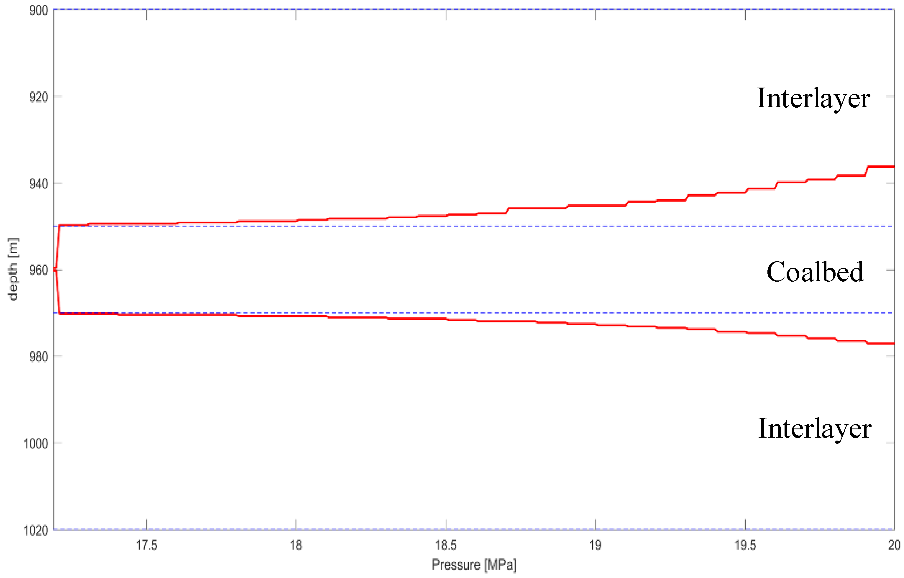
The T-type fracture consists of a vertical fracture and a horizontal fracture, as shown in Figure 1. The study [13] shows that when coal is fractured, a vertical fracture is first formed, and after the vertical fracture extends from the upper and lower tips to the horizontal bedding and other structural weak surfaces, the bedding opens and propagates under the pressure of the fracturing fluid to form a T-shape fracture. Therefore, we first establish a mechanical model of vertical fracture opening, and then calculate the opening length of the horizontal fracture based on the vertical fracture opening, and finally obtain a T-type fracture model.
The physical model of height of vertical fracture is shown in Figure 2 [23]. Figure 2 shows that the fracture is extending from top to bottom in six different formations. This hypothesis has fully taken the phenomenon of delamination into account when the vertical fracture propagates to different lithologic formations. This model only represented six layers for the sake of simplicity, but it is not limited to the number of layers and can be extended to n layers.
Corresponding to the vertical fracture shown in Figure 2, the SIF at the upper and lower tips of the fracture can be expressed as [23]:
K I = 1 π C C C P n e t ( x ) C x C + x d x
K I + = 1 π C C C P n e t ( x ) C + x C x d x
where: C is half height of fracture, m; Pnet(x) is net pressure of fluid at any point in the fracture, MPa; hi is the thickness of the i-th layer, i = 1, 2, …., n, m; σi is the horizontal minimum principal stress of the i-th layer, i = 1, 2, …., n, MPa; KICi is the fracture toughness of the i-th layer, i = 1, 2, …, n, MPa·m1/2.
P n e t ( x ) = ρ g x + b i = m x + b i
b i = P r e f + ρ g ( d m i d d r e f ) σ i
where m = ρg; ρ is fracturing fluid density, kg/m3; dref is true vertical depth (TVD) for perforation, m; Pref is fracturing fluid pumping pressure at perforation, MPa; dmid is TVD in the middle of the fracture, m; Pmid is the pressure of fracturing fluid in the middle of the fracture, MPa.
Substituting (3) and (4) into (1) and (2), we can obtain:
K I + = 1 π C C C ( m x + b i ) C + x C x d x
K I = 1 π C C C ( m x + b i ) C x C + x d x
By integrating Equations (5) and (6), the SIF at the top and bottom of the fracture can be obtained. The SIF at the lower end of the fracture corresponding to any position x on the fracture is:
K I + ( m , b i , x ) = 2 C C x ( 2 b i + m C ) sin 1 ( C + x 2 C ) ( C x ) C + x [ 2 b i + m ( 2 C + x ) ] 2 π C ( C x )
K I + ( m , b i , C ) = 0 , x = C
K I + ( m , b i , C ) = 1 2 ( 2 b i + m C ) π C , x = C
Therefore, we can obtain that the SIF at the lower end of the fracture in the i-th layer is:
K I + , i = K I + ( m , b i , x d , i ) K I + ( m , b i , x u , i )
where xd,i and xu,i are the bottom and top depth of the i-th layer respectively, m.
In this way, the total SIF at the lower end of fracture extending in a multi-layered stratum is:
K I + = i = 1 n [ K I + ( m , b i , x d , i ) K I + ( m , b i , x u , i ) ]
With the same derivation method, we can get the total SIF at the upper end of the fracture as:
K I = i = 1 n [ K I ( m , b i , x u , i ) K I ( m , b i , x d , i ) ]
Whether the upper or lower fracture can extend in the stratum depends on the relative magnitudes of the SIF at the upper and lower tips of the fracture and the fracture toughness of the coal at the fracture tip. When Equation (13) is satisfied, the height of vertical fracture will increase, and the formation will be ruptured, and fractures will continue to extend upwards or downwards to increase the fracture height:
{ The   condition   of   the   upper   fracture :    K I K I C i The   condition   of   the   lower   fracture :    K I + K I C i
As shown in Figure 3, when the vertical fracture encounters the coal bedding, under the action of stresses generated by the vertical fracture tip and the in-situ stresses, the bedding is stretched or sheared to form a T-shape fracture.
Since the angle between bedding and horizontal plane is small, there is almost no difference in the difficulty of opening the right and left sides of the horizontal fracture [13]. The morphology of fracture is more likely to be a T-type. Considering the actual bedding dip is nearly to zero, the bedding in this model can be simplified to be parallel to the horizontal plane and perpendicular to the vertical fracture.
The normal stress and shear stress generated by the in-situ stress on the horizontal bedding plane are [24]:
σ n = σ v + σ h 2 σ v σ h 2 cos 2 α
τ = σ v σ h 2 sin 2 α
where α is the angle between horizontal bedding and vertical stress, (°).
When the vertical fracture encounters the horizontal bedding, the distance from the vertical fracture tip to the horizontal bedding plane is r, and the stresses induced by the vertical fracture are:
σ x F = K I 2 π r cos θ 2 ( 1 sin θ 2 sin 3 2 θ )
σ y F = K I 2 π r cos θ 2 ( 1 + sin θ 2 sin 3 2 θ )
τ x y F = K I 2 π r cos θ 2 sin θ 2 cos 3 2 θ
where: θ is the polar angle of any point in the polar coordinate system of the fracture tip deviating from the direction of the fracture extension line, (°); KI indicates the SIF factor at the vertical fracture tip, when it corresponds to the lower end of the fracture, it is the result of Equation (11), and when it corresponds to the upper end of the fracture, it is the result of Equation (12).
The normal stress and shear stress applied to the fracture surface by converting the stress induced by the vertical fracture are [25]:
σ n F = σ x F sin 2 β + σ y F cos 2 β + 2 τ x y F cos β sin β
τ F = ( σ y F σ x F ) cos β sin β + τ x y F ( cos 2 β sin 2 β )
where β is the angle between the horizontal bedding polar coordinate system and vertical fracture rectangular coordinate system, (°).
As for the horizontal bedding, the corresponding α = β = θ = 90°, it can be obtained that the horizontal bedding stresses under the action of the vertical fracture and the in-situ stresses are as follows:
σ n = σ n + σ n F = σ v + K I 4 π r
τ = τ + τ F = K I 4 π r
Therefore, for horizontal bedding, if Equation (23) is satisfied, tensile failure will occur to form horizontal fracture, and if Equation (24) is satisfied, shear failure will occur and horizontal fracture will be formed. According to Equations (23) and (24), the length of the horizontal fracture can be determined in terms of the critical conditions of failure, and then the morphology of the T-type fracture can be determined.
σ n σ t
τ τ s
where σt is the tensile strength of the bedding plane, MPa; τs is the cohesion of the bedding plane, MPa.

3. Model Validation

Due to the lack of field fracturing application data and microseismic data for fracture monitoring, the verification of the model is relatively difficult. For this reason, a hydraulic fracturing simulation experiment on a large-size coal sample was carried out in this paper. It was hoped that the correctness of the model could be verified by experimental simulation. The size of the fracturing coal sample is 300 × 300 × 300 mm, the internal coal rock size is 250 × 250 × 250 mm, and the thickness of the externally wrapped cement sample is 25 mm. T-type fractures were formed after the coal sample was fractured, vertical fractures were formed in the middle of the coal, and horizontal fractures were formed at the interface between the coalbed and the cement sample, as shown in the right picture in Figure 4. In fact, horizontal fractures can be formed in any structurally weak plane. In this paper, we only discuss the situation where the horizontal fracture occurs in the interface. The parameters and fracture parameters involved in the fracturing process are shown in Table 1.
Using the data in Table 1, the length of horizontal fracture that may be generated is calculated by trial calculation according to the T-type fracture model established in Section 2, and the calculated results are recorded in Table 2. As a result of trial calculation, it is proved that the tensile stress caused by vertical fracture is much smaller than the vertical stress imposed by the simulation, therefore tensile failure cannot occur and only shear failure can occur. Therefore, in Table 2, only the fracture toughness and coal-cement interface shear strength values corresponding to the three different levels of fracture lengths are listed.
According to the results shown in Table 2, when the horizontal fracture length of the T-type fracture is 0.05–0.15 m, the shear strength value of the bedding plane of coal and roof is 0.48–0.84 MPa, and the corresponding fracture toughness is 0.94 MPa·m1/2. The result accords with the actual mechanical parameters of coal rock, which shows that the calculation result of this model is correct.

4. Analysis of Influence Factors of T-Type Fracture

In order to analyze the factors affecting the shape of the T-type fracture in the case approaching a true formation, the calculation parameters are assumed to be as shown in Table 3. In the case where the formation contains three layers, the upper and lower layers are interlayers, and the middle layer is a coal layer. The in-situ stress, fracture toughness, and tensile and shear strength at the top of each layer are different, and the perforation location is 960 m in the middle of the coalbed. Through calculations, the height of vertical fracture variation in coalbed is shown in Figure 5. When the injection pressure reaches 17.20 MPa, the fracture starts to grow quickly and extends to the top and bottom interfaces of the coalbed, and with the injection pressure in the perforation hole increases, fracture will extend up and down through the layers into the interlayers. Before a fracture passes through the interface, the T-shape fracture profile formed at the top interface of the coalbed is shown in Figure 6. The calculations show that under the stress conditions in this paper, the tensile stress induced by the vertical fracture is much smaller than the vertical stress acting on the bedding plane, and the interface at the top of the coalbed can only undergo shear failure and form a T-type fracture.
For the analysis of each influencing factor, a single factor analysis method is used to ensure that other parameters remain unchanged (as shown in Table 3) and only the analyzed parameter is changed to calculate the influence of this parameter on the shape of T-type fracture. In order to be able to evaluate the influence of various factors on the shape of T-shaped fracture in a unified manner, the ratio of the length of horizontal fracture and the length of vertical fracture is defined as:
T h v = 2 C l f
Equation (25) can be used to apparently reflect the changes of the morphology of T-type fracture, and to analyze the proportional relationship between horizontal fracture and vertical fracture of T-type fracture under different factors.

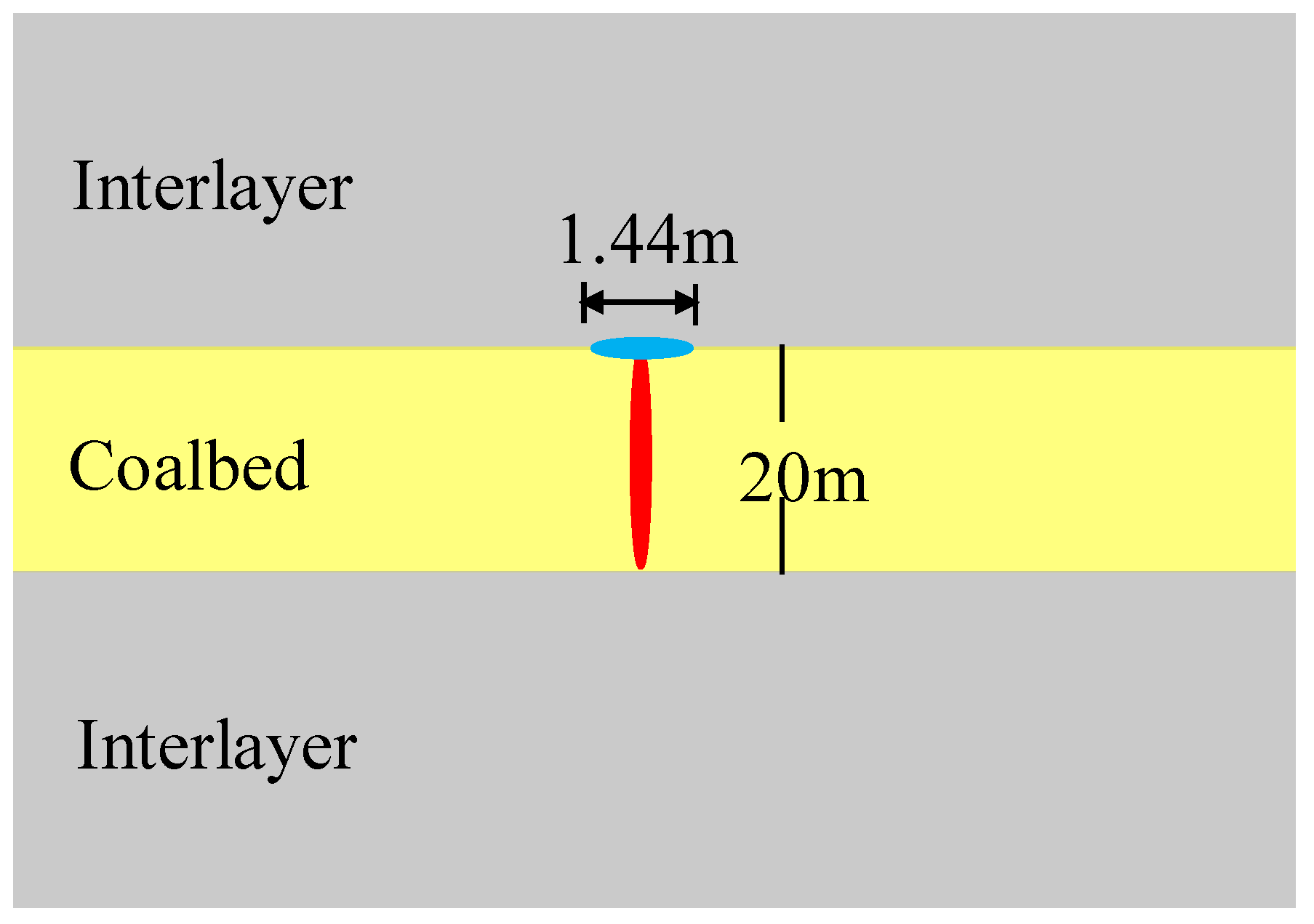
4.1. Effect of Vertical Fracture Height on the Shape of T-Type Fracture

Increasing the thickness of coalbed from 10 m to 50 m by the interval of 10 m, we calculate and analyze the fracture morphology caused by the change of vertical fracture height in the coalbed, as shown in Figure 7.
According to the results of Figure 7, it can be seen that as the vertical fracture height increases, the horizontal fracture length increases, and when the vertical fracture height is 10 m, a horizontal fracture with 1.24 m long can be generated. When the vertical fracture height increases to 50 m, it can produce a 2.76 m long horizontal fracture. However, through the change of Thv, it can be seen that the value of Thv decreases at first and tends to be stable as the vertical fracture height increases. This shows that when the vertical fracture height increases to a certain value, the horizontal fracture length is no longer obviously affected by the vertical fracture height.

4.2. Influence of Coalbed Fracture Toughness on T-Type Fracture

Increase the fracture toughness of coalbed from 0.21 to 2.21 MPa·m1/2 by the interval of 0.5 MPa·m1/2, and keep the other parameters unchanged. The influence of the fracture toughness of the coalbed on the fracture morphology is analyzed and the calculation results are plotted as shown in Figure 8.
From the curve in Figure 8, it can be concluded that as the fracture toughness of coal increases, the length of the horizontal fracture remains constant. When the fracture toughness reaches a certain value, the length of the horizontal fracture increases rapidly with the fracture toughness. This shows that there is a certain threshold value. When the fracture toughness is smaller than the threshold, the length of horizontal fracture will not be affected with the fracture toughness increasing. Above this threshold, the fracture toughness will have a significant effect on the length of horizontal fracture. Threshold in this example is 0.71 MPa·m1/2. The variation law of Thv is exactly the same as that of horizontal fracture length. When the fracture toughness of coal increases from 0.21 to 2.21 MPa·m1/2, the Thv increases from 0.07 to 0.457 MPa·m1/2.

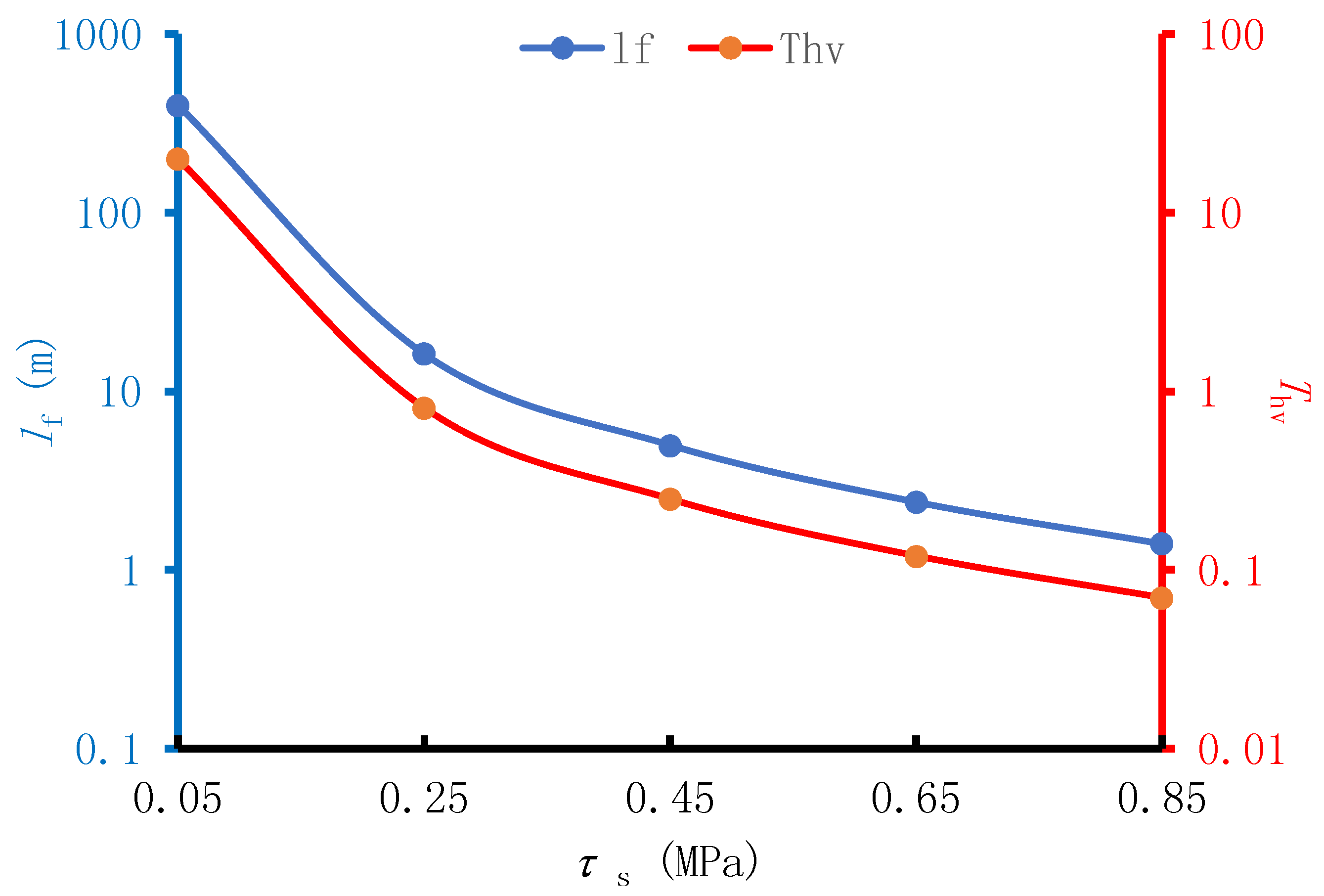
4.3. Influence of Bedding Shear Strength on the Morphology of T-Type Fracture

The calculation example in this paper shows that the horizontal fracture formed with the stress of overlying formation is caused by shear failure. Therefore, only the effects of bedding shear strength on the morphology of T-type fracture need to be analyzed. Decrease the shear strength from 0.85 MPa to 0.05 MPa, the interval is 0.2 MPa, and analyze the T-type fracture morphology changes.
From the curve results in Figure 9, we can see that as the shear strength of the interface between the coalbed and the interlayer increases, the length of the horizontal fracture rapidly decreases. The horizontal fracture length is 400 m when the shear strength is 0.05 MPa. When the shear strength increases to 0.85 MPa, only a horizontal fracture of 1.4 m can be formed. Since there is no change in the vertical fracture height, the change law of Thv is consistent with that of horizontal fracture length.

5. Discussion

5.1. Principal Insights

This paper has established the calculation model of T-type fracture of coal hydraulic fracturing. The model has taken into account the extension characteristics of vertical fracture in multi-layered formations and calculated the stress of horizontal fractures according to the SIF at the vertical fracture tip. According to the tensile and shear failures, the horizontal fracture length was determined. The results of this study show that under the action of the overlying rock stress on the horizontal bedding plane, it is hard for tensile failure to occur, and shear fracture occurs mainly to form horizontal fractures. The increase of vertical fracture height and fracture toughness of coal is beneficial to the increase of horizontal fracture length. The shear strength of coalbed and interlayer has great influence on the length of horizontal fracture, and the fracture length decreases rapidly with the increase of shear strength.

5.2. Model Limitations

There are still many areas need to be continually studied in the future. For example, the model did not consider the change of the stress field caused by the change of pore pressure, which is caused by the loss of fracturing fluid. This may cause a certain deviation from the actual situation. In addition, the model mainly focused on the mechanical conditions for forming horizontal fractures at the interface between the coalbed and the interlayer and did not consider the mechanics issue of further fracture propagation by the sequential injection of fracturing fluids after the formation of horizontal fractures. This also requires a follow-up study to give a better explanation of the problem.

6. Conclusions

A calculation model of T-type fracture in coal was established based on the physical phenomena of formation of horizontal fracture along the interface of coalbed after vertical fracture was formed by hydraulic fracturing in coalbed, which formed a special T-type fracture. This model provided a good theoretical reference for fracturing design of complex fracture in coalbed. The following systematic insights were obtained by applying the model to a synthetic case study, expanded with a sensitivity analysis to various key parameters:
(1)
T-type fractures in coal fracturing are mainly caused by vertical fractures extending to the bedding plane and causing horizontal fractures to form on the bedding plane after stretching or shear failure.
(2)
The increase of the vertical fracture height can increase the length of the horizontal fracture, but when the vertical fracture height increases to a certain value, the effect of increasing the horizontal fracture length by increasing the vertical fracture height is no longer obvious.
(3)
The fracture toughness has certain influence on the length of horizontal fracture, but there is a threshold. When the fracture toughness is less than the threshold, the length of horizontal fracture remains unchanged, otherwise, the length of horizontal fracture increases rapidly with the increase of fracture toughness.
(4)
When the shear strength of the interface between the coalbed and the interlayer is enhanced, the length of the horizontal part of T-type fracture is rapidly reduced. It shows that the greater the stratification strength is, the more stable it is and the less favorable it is to the formation of T-type fracture.

Author Contributions

Y.L. developed the model. Y.L. and D.J. designed and analyzed the synthetic cases. Y.L., K.Z. and W.L. wrote the manuscript. All authors reviewed the manuscript.

Acknowledgments

This research was supported by the Natural Science Foundation for Youth of China (No. 51504068), Northeast Petroleum University Scientific Research Start Funds Subsidization Project, National Science and Technology Major Project of China (2016ZX05046004-004), and National Natural Science Foundation of China (No. 51490650).

Conflicts of Interest

The authors declare no conflict of interest.

Nomenclature

σHmaximum horizontal principal stress, MPa;
σhminimum horizontal principal stress, MPa;
σvvertical stress, MPa;
lflength of horizontal fracture, m;
Prfracture propagation pressure, MPa;
Cthe half height of the vertical fracture, m;
Pnet(x)the net pressure of the fluid at any point in the fracture, MPa;
hithe thickness of the i-th layer, I = 1, 2, …., n, m;
σIthe horizontal minimum principal stress of the i-th layer, I = 1, 2, …., n, MPa;
KICithe fracture toughness of the i-th layer rock, I = 1, 2, …., n, MPa·m1/2;
TVDthe true vertical depth, m;
ρthe fracturing fluid density, kg/m3;
mthe density gradient, kg/m2·s2;
drefthe vertical depth of perforation, m;
Prefthe fracturing fluid pumping pressure at the perforation location, MPa;
dmidthe vertical depth of the middle of the fracture, m;
Pmidthe fracturing fluid pressure in the middle of the fracture, MPa;
xd,I, xu,Ithe bottom and top depth of the i-th layer respectively, m;
αthe angle between horizontal bedding and vertical stress, (°);
θthe polar angle of any point in the polar coordinate system of the fracture tip deviating from the direction of the fracture extension line, (°);
βthe angle between the horizontal bedding polar coordinate system and vertical fracture rectangular coordinate system, (°);
σtthe tensile strength of the bedding plane, MPa;
τsthe cohesion of the bedding plane, MPa.

References

  1. Song, D.; Liu, Z.; Wang, E.; Qiu, L.; Gao, Q.; Xu, Z. Evaluation of coal seam hydraulic fracturing using the direct current method. Int. J. Rock Mech. Min. Sci. 2015, 78, 230–239. [Google Scholar] [CrossRef]
  2. Li, Y.; Jia, D.; Wang, M.; Liu, J.; Fu, C.; Yang, X.; Ai, C. Hydraulic fracturing model featuring initiation beyond the wellbore wall for directional well in coal bed. J. Geophys. Eng. 2016, 13, 536–548. [Google Scholar] [CrossRef]
  3. Li, Y.; Jia, D.; Liu, J.; Fu, C.; Ai, C. The calculation method based on the equivalent continuum for the fracture initiation pressure of fracturing of coalbed methane well. J. Petrol. Sci. Eng. 2016, 146, 909–920. [Google Scholar] [CrossRef]
  4. Cheng, L.; Ge, Z.; Xia, B.; Li, Q.; Tang, J.; Cheng, Y.; Zuo, S. Research on Hydraulic Technology for Seam Permeability Enhancement in Underground Coal Mines in China. Energies 2018, 11, 427. [Google Scholar] [CrossRef]
  5. Chong, Z.; Li, X.; Chen, X.; Zhang, J.; Lu, J. Numerical Investigation into the Effect of Natural Fracture Density on Hydraulic Fracture Network Propagation. Energies 2017, 10, 914. [Google Scholar] [CrossRef]
  6. Li, Y.; Jia, D.; Rui, Z.; Peng, J.; Fu, C.; Zhang, J. Evaluation Method of Rock Brittleness Based on Statistical Constitutive Relations for Rock Damage. J. Petrol. Sci. Eng. 2017, 153, 123–132. [Google Scholar] [CrossRef]
  7. Tang, J.; Wu, K.; Zeng, B.; Huang, H.; Hu, X.; Guo, X.; Zuo, L. Investigate Effects of Weak Bedding Interfaces on Fracture Geometry in Unconventional Reservoirs. J. Petrol. Sci. Eng. 2018, 165, 992–1009. [Google Scholar] [CrossRef]
  8. Rui, Z.; Guo, T.; Feng, Q.; Qu, Z.; Qi, N.; Gong, F. Influence of Gravel on the Propagation Pattern of Hydraulic Fracture in the Glutenite Reservoir. J. Petrol. Sci. Eng. 2018, 165, 627–639. [Google Scholar] [CrossRef]
  9. Guo, J.; Luo, B.; Lu, C.; Lai, J.; Ren, J. Numerical Investigation of Hydraulic Fracture Propagation in A Layered Reservoir using the Cohesive Zone Method. Eng. Fract. Mech. 2017, 186, 195–207. [Google Scholar] [CrossRef]
  10. Rui, Z.; Cui, K.; Wang, X.; Lu, J.; Chen, G.; Ling, K.; Patil, S. A Quantitative Framework for Evaluating Unconventional Well Development. J. Petrol. Sci. Eng. 2018, 166, 900–905. [Google Scholar] [CrossRef]
  11. Chen, T.; Wang, Z.; Yang, G. Experiments of fracturing and pressure curve analysis of T-shape fractures of coalbed. Spec. Oil Gas Reserv. 2013, 20, 123–126. [Google Scholar] [CrossRef]
  12. Wu, X.; Xi, C.; Wang, G. The mathematic model research of complicated fractures system in coalbed methane wells. Nat. Gas Ind. 2006, 26, 124–126. [Google Scholar]
  13. Li, Y.; Rui, Z.; Zhao, W.; Bo, Y.; Fu, C.; Chen, G.; Patil, S. Study on the mechanism of rupture and propagation of T-type fractures in coal fracturing. J. Nat. Gas Sci. Eng. 2018, 52, 379–389. [Google Scholar] [CrossRef]
  14. Jeffrey, R.G.; Zhang, X.; Thiercelin, M.J. Hydraulic fracture offsetting in naturally fractures reservoirs: Quantifying a long-recognized process. In Proceedings of the SPE Hydraulic Fracturing Technology Conference, Woodlands, TX, USA, 19–21 January 2009. [Google Scholar]
  15. Zhang, G.; Chen, M. Complex fracture shapes in hydraulic fracturing with orientated perforations. Petrol. Explor. Dev. 2009, 36, 103–107. [Google Scholar] [CrossRef]
  16. Zhang, G.; Chen, M. The relationship between the production rate and initiation location of new fractures in a refractured well. Petrol. Sci. Technol. 2010, 28, 655–666. [Google Scholar] [CrossRef]
  17. Zhou, J.; Jin, Y.; Chen, M. Experimental investigation of hydraulic fracturing in random naturally fractured blocks. Int. J. Rock Mech. Min. Sci. 2010, 47, 1193–1199. [Google Scholar] [CrossRef]
  18. Chuprakov, D.A.; Akulich, A.V.; Siebrits, E.; Thiercelin, M. Hydraulic-fracture propagation in a naturally fractured reservoir. SPE Prod. Oper. 2011, 26, 88–97. [Google Scholar] [CrossRef]
  19. Hou, B.; Chen, M.; Wang, Z.; Yuan, J.; Liu, M. Hydraulic fracture initiation theory for a horizontal well in a coal seam. Petrol. Sci. 2013, 10, 219–225. [Google Scholar] [CrossRef]
  20. Mohammad, A.; Sheik, S. Initiation of a secondary hydraulic fracture and its interaction with the primary fracture. Int. J. Rock Mech. Min. Sci. 2010, 47, 714–722. [Google Scholar] [CrossRef]
  21. Tang, S.; Zhu, B.; Yan, Z. Effect of crustal stress on hydraulic fracturing in coalbed methane wells. J. China Coal Soc. 2011, 36, 65–69. [Google Scholar] [CrossRef]
  22. Zhu, H.; Deng, J.; Jin, X.; Hu, L.; Luo, B. Hydraulic fracture initiation and propagation from wellbore with oriented perforation. Rock Mech. Rock Eng. 2015, 48, 585–601. [Google Scholar] [CrossRef]
  23. Liu, S.; Valkó, P.P. A rigorous hydraulic-fracture equilibrium-height model for multilayer formations. SPE Prod. Oper. 2017, 8, 1–21. [Google Scholar] [CrossRef]
  24. Zhi, L.; Changgui, J.; Chunhe, Y.; Yijin, Z.; Yintong, G.; Shuai, H. Propagation of hydraulic fissures and bedding planes in hydraulic fracturing of shale. Chin. J. Rock Mech. Eng. 2015, 34, 12–20. [Google Scholar] [CrossRef]
  25. Chuprakov, D.A.; Zhubayev, A.S. A variational approach to analyze a natural fault with hydraulic fracture based on the strain energy density criterion. Theor. Appl. Fract. Mech. 2010, 53, 221–232. [Google Scholar] [CrossRef]
Figure 1. T-type fracture in coal: (a) Front view; (b) Side view [13].
Energies 11 01196 g001
Figure 2. Physical model of vertical fracture extension.
Energies 11 01196 g002
Figure 3. Physical model of T-type fracture.
Energies 11 01196 g003
Figure 4. Morphology of hydraulic fracturing fractures in large-size coal sample. (a) A schematic diagram of loading direction and coal sample; (b) A schematic of vertical fracture and horizontal fracture after hydraulic fracturing.
Energies 11 01196 g004
Figure 5. The changes of fracture height with injection pressure at the perforation.
Energies 11 01196 g005
Figure 6. Vertical fracture morphology with injection pressure value of 17.30 MPa at perforation.
Energies 11 01196 g006
Figure 7. The length of horizontal fracture and the shape of T-type fracture change with the height of vertical fracture.
Energies 11 01196 g007
Figure 8. The length of horizontal fracture and the morphology of T-type fracture change with fracture toughness of coal.
Energies 11 01196 g008
Figure 9. Changes of the length of horizontal fracture and the shape of T-type fracture with the shear strength of coalbed interface.
Energies 11 01196 g009
Table 1. Coal fracturing test parameters and statistics of fracture parameters.
No.ParametersSymbolUnitValue
1maximum horizontal principal stressσHMPa6
2minimum horizontal principal stressσhMPa4
3vertical stressσvMPa10
4length of vertical fracture2Cm0.25
5length of horizontal fracturelfm0.05–0.15
6fracture propagation pressurePrMPa5.5
7fracturing fluid densityρkg/m31050
Table 2. T-type fracture model trial results.
No. 1No. 2No. 3
SymbolUnitValueSymbolUnitValueSymbolUnitValue
KICMPa·m1/20.94KICMPa·m1/20.94KICMPa·m1/20.94
τMPa0.84τMPa0.59τsMPa0.48
lfm0.05lfm0.10lfm0.15
Table 3. Assumptions for the analysis of the influence of T-type fracture.
No. of LayerTop Depth (m)Thickness (m)Minimum Horizontal Principal Stress (MPa)Vertical Stress (MPa)Fracture Toughness (MPa·m1/2)Tensile Strength (MPa)Shear Strength (MPa)
19005020.7021.601.420.913.49
29502016.4022.800.710.320.85
39705022.3023.301.420.933.62

