Economics of Renewable Energy Integration and Energy Storage via Low Load Diesel Application


Abstract
: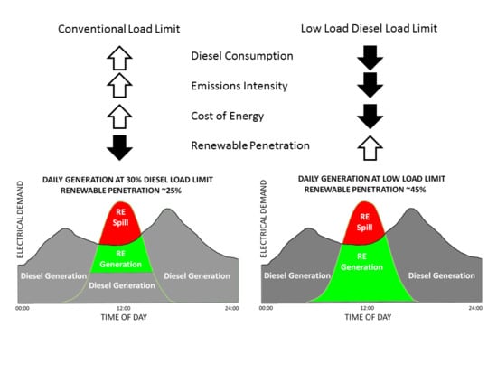
1. Introduction
2. Results
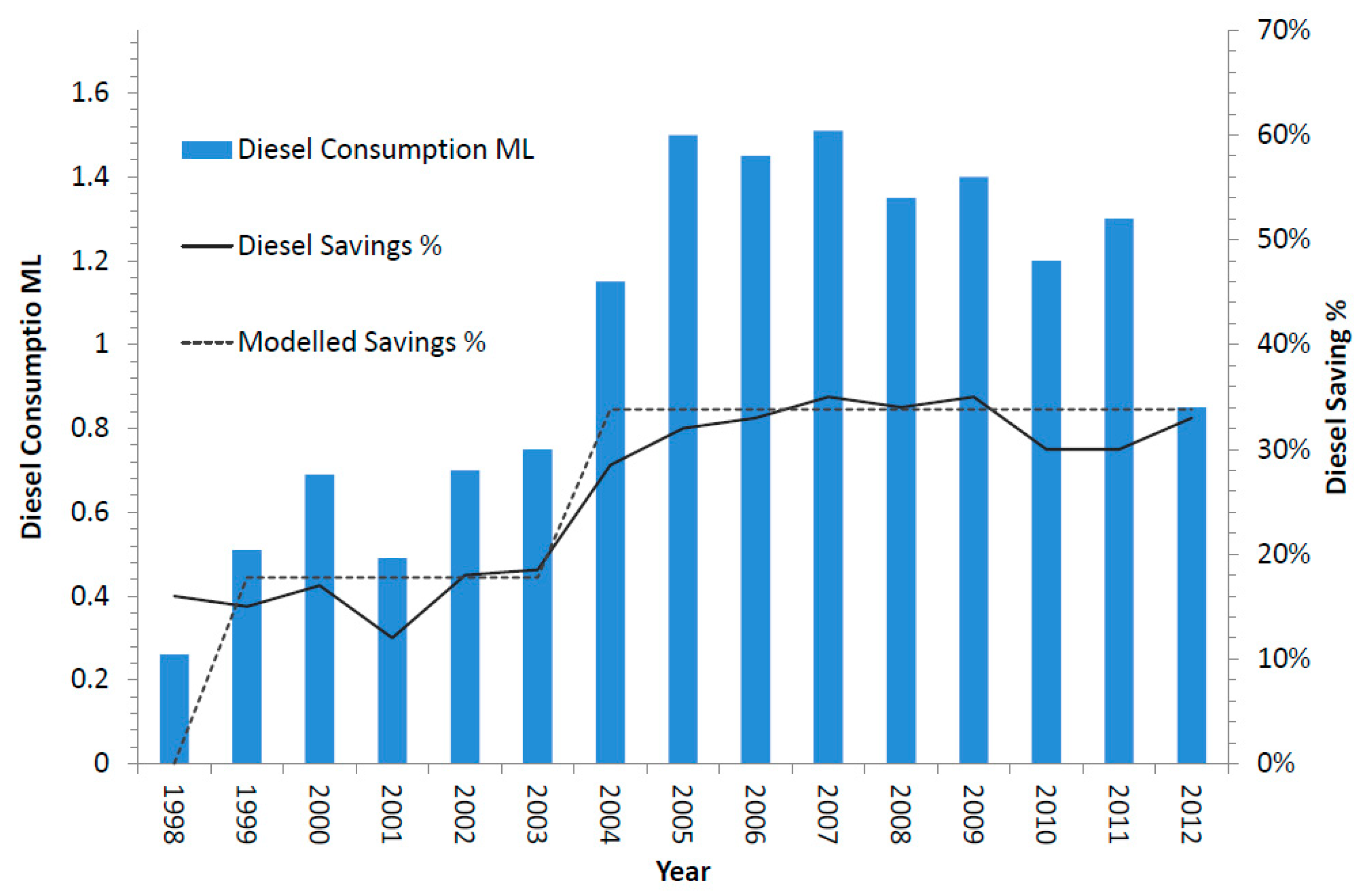
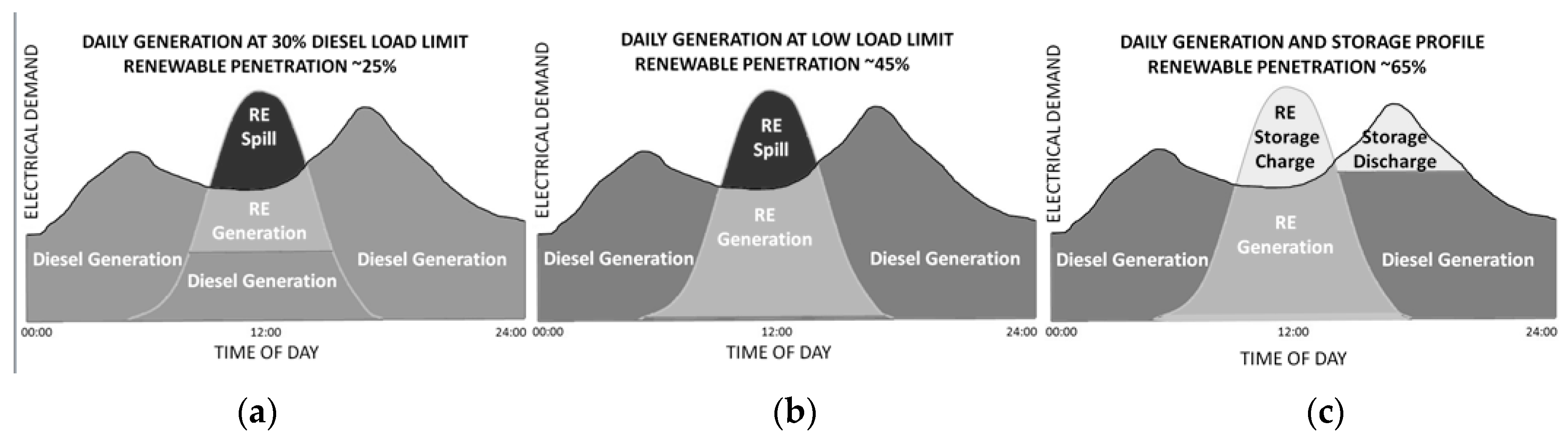
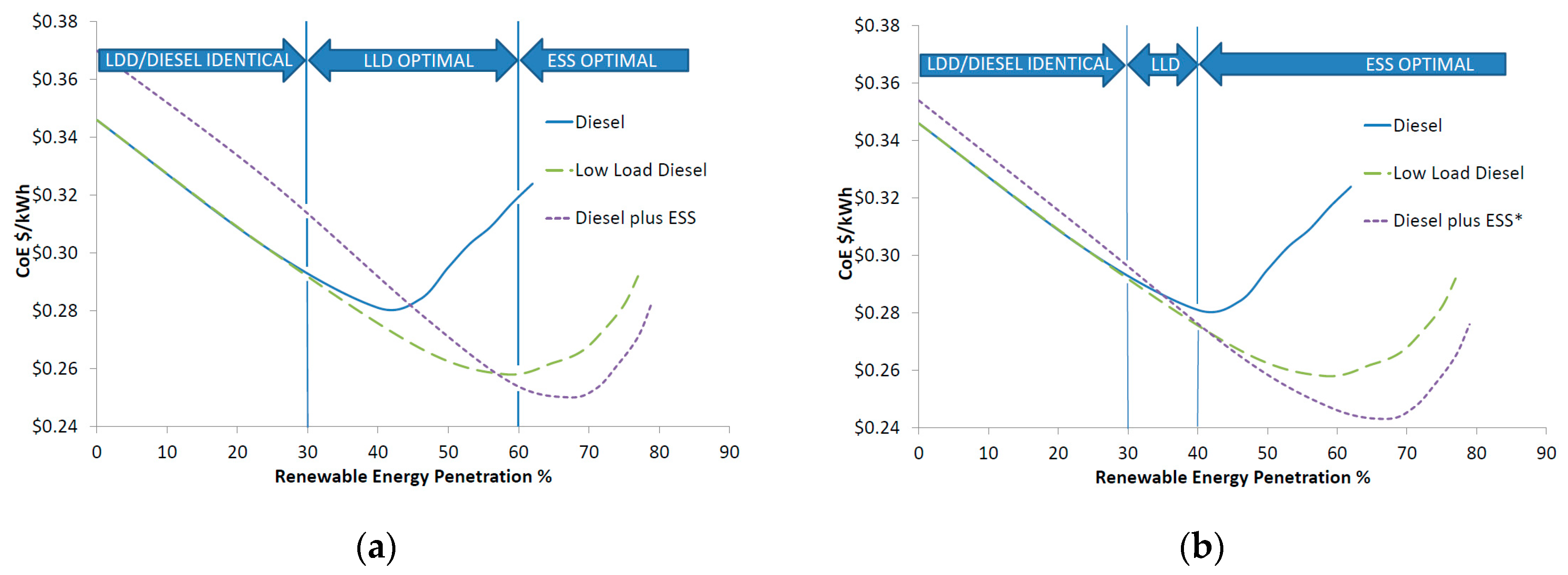
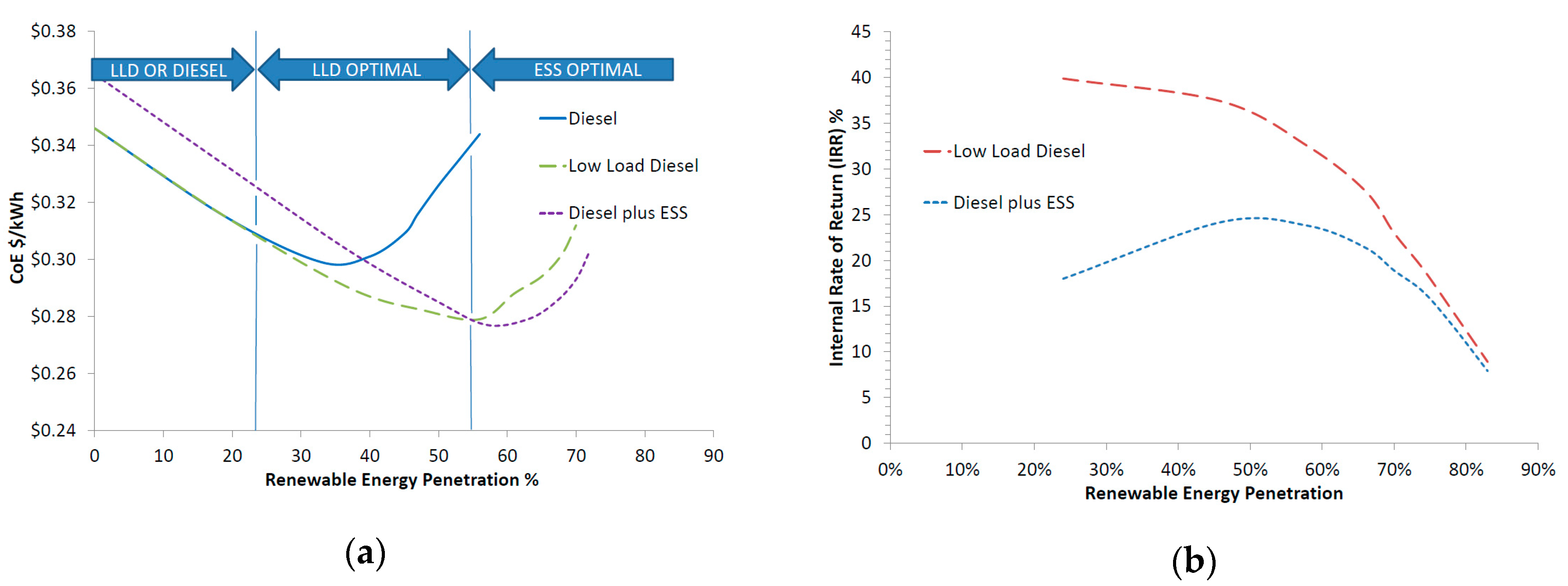
2.1. Economic Modeling
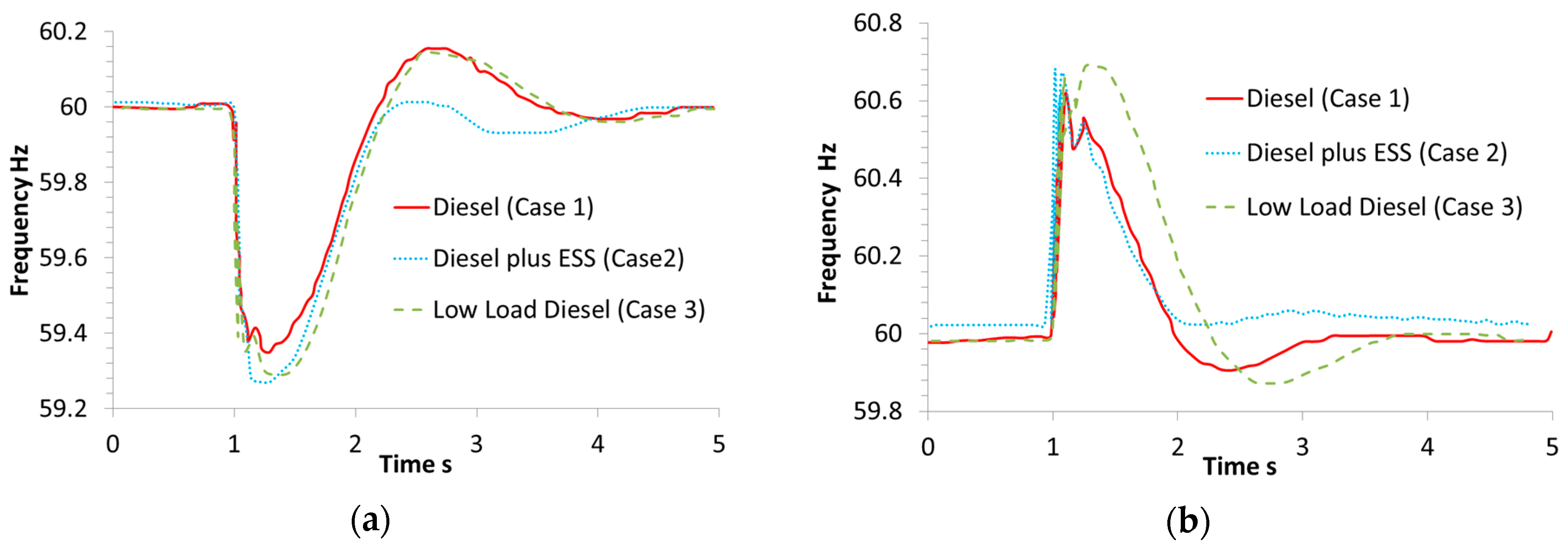
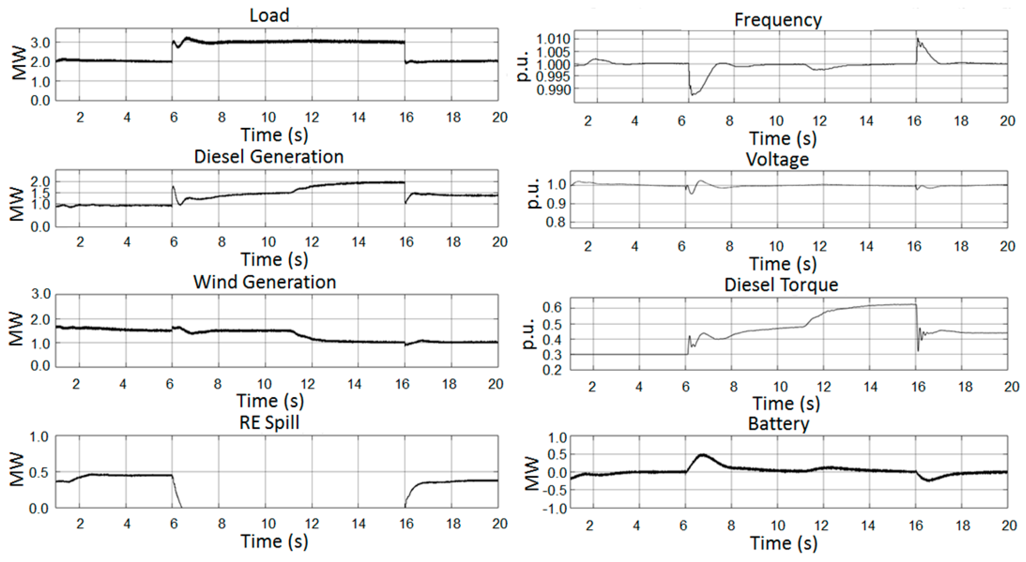
2.2. Transient Response Simulation
2.2.1. Case 1—Conventional Diesel and Wind System
2.2.2. Case 2—Conventional Diesel, Wind, Plus Energy Storage System (ESS)
2.2.3. Case 3—Low Load Diesel and Wind System
3. Discussion
4. Materials and Methods
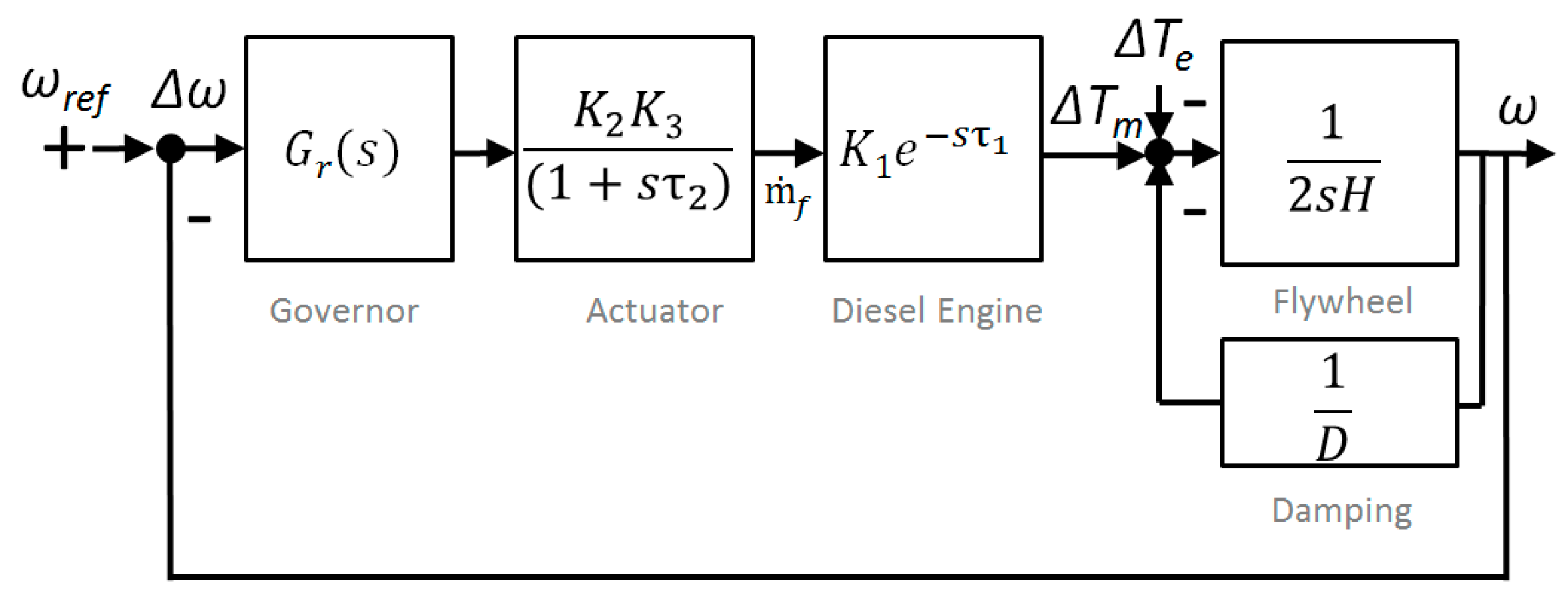
4.1. Diesel Generation Modeling
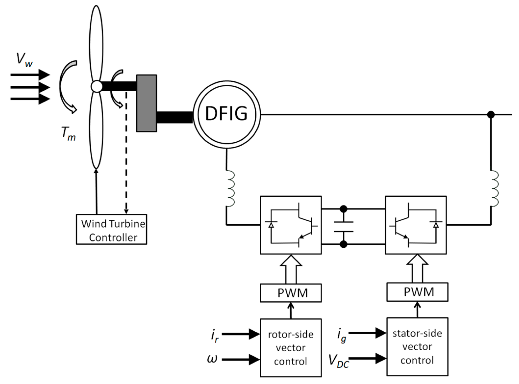
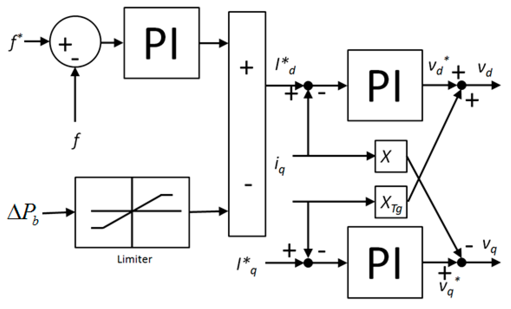
4.2. Wind Generation Modeling
4.3. Energy Storage System (ESS) Modeling
5. Conclusions
Author Contributions
Acknowledgments
Conflicts of Interest
References
- Micangeli, A.; del Citto, R.; Kiva, I.N.; Santori, S.G.; Gambino, V.; Kiplagat, J.; Viganò, D.; Fioriti, D.; Poli, D. Energy Production Analysis and Optimization of Mini-Grid in Remote Areas: The Case Study of Habaswein, Kenya. Energies 2017, 10, 2041. [Google Scholar] [CrossRef]
- Akinyele, D.; Belikov, J.; Levron, Y. Challenges of Microgrids in Remote Communities: A STEEP Model Application. Energies 2018, 11, 432. [Google Scholar] [CrossRef]
- Hamilton, J.; Negnevitsky, M.; Wang, X. Low load diesel perceptions and practices within remote area power systems. In Proceedings of the International Symposium on Smart Electric Distribution Systems and Technologies (EDST), Vienna, Austria, 8–11 September 2015; pp. 121–126. [Google Scholar]
- Arriaga, M.; Cañizares, C.A.; Kazerani, M. Renewable Energy Alternatives for Remote Communities in Northern Ontario, Canada. IEEE Tran. Sustain. Energy 2013, 4, 661–670. [Google Scholar] [CrossRef]
- Al-Hammad, H.; Becjer, T.; Bode, A.; Gupta, S.; Kreibiehl, S. Renewable Energy in Hybrid Mini-Grids and Isolated Grids: Economic Benefits and Business Cases; FS-UNEP Collaborating Centre for Climate & Sustainable Energy Finance: Frankfurt, Germany, 2015; Available online: http://fs-unep-centre.org/sites/default/files/publications/hybridgrids-economicbenefits.pdf (accessed on 11 February 2018).
- Elmitwally, A.; Rashed, M. Flexible Operation Strategy for an Isolated PV-Diesel Microgrid without Energy Storage. IEEE Trans. Energy Convers. 2011, 26, 235–244. [Google Scholar] [CrossRef]
- Nayar, C. Innovative Remote Micro-Grid Systems. Int. J. Environ. Sustain. 2012, 1, 53–65. [Google Scholar] [CrossRef]
- Nikolic, D.; Negnevitsky, M.; de Groot, M.; Gamble, S.; Forbes, J.; Ross, M. Fast demand response as an enabling technology for high renewable energy penetration in isolated power systems. In Proceedings of the IEEE PES General Meeting, National Harbor, MD, USA, 27–31 July 2014; pp. 1–5. [Google Scholar]
- Hamilton, J.; Negnevitsky, M.; Wang, X. Economic Rationalization of Energy Storage under Low Load Diesel Application. Energy Procedia 2017, 110, 65–70. [Google Scholar] [CrossRef]
- Li, W.Y.; Bagen, B. Reliability evaluation of integrated wind/diesel/storage systems for remote locations. In Proceedings of the IEEE 11th International Conference on Probabilistic Methods Applied to Power Systems (PMAPS), Singapore, 14–17 June 2010; pp. 791–795. [Google Scholar]
- Xu, L.; Islam, S.; Chowdhury, A.A.; Koval, D.O. Reliability evaluation of a wind-diesel-battery hybrid power system. In Proceedings of the Industrial and Commercial Power Systems Technical Conference, Clearwater Beach, FL, USA, 4–8 May 2008; pp. 1–8. [Google Scholar]
- Mendis, N.; Muttaqi, K.M.; Perera, S.; Kamalasadan, S. An Effective Power Management Strategy for a Wind–Diesel–Hydrogen-Based Remote Area Power Supply System to Meet Fluctuating Demands under Generation Uncertainty. IEEE Trans. Ind. Appl. 2015, 51, 1228–1238. [Google Scholar] [CrossRef]
- Kayikci, M.; Milanovic, J.V. Dynamic Contribution of DFIG-Based Wind Plants to System Frequency Disturbances. IEEE Trans. Power Syst. 2009, 24, 859–867. [Google Scholar] [CrossRef]
- Mendis, N.; Muttaqi, K.M.; Perera, S.; Uddin, M.N. A novel control strategy for stand-alone operation of a wind dominated RAPS system. In Proceedings of the 2011 46th IEEE Industry Applications Society Annual Meeting, Orlando, FL, USA, 9–13 October 2011. [Google Scholar]
- Haruni, M.O.; Gargoom, A.; Haque, M.E.; Negnevitsky, M. Dynamic operation and control of a hybrid wind-diesel stand alone power systems. In Proceedings of the Applied Power Electronics Conference and Exposition (APEC), Palm Springs, CA, USA, 21–25 February 2010; pp. 162–169. [Google Scholar]
- Zhu, B.; Tazvinga, H.; Xia, X. Switched Model Predictive Control for Energy Dispatching of a Photovoltaic-Diesel-Battery Hybrid Power System. IEEE Trans. Control Syst. Technol. 2015, 23, 1229–1236. [Google Scholar]
- Changjie, Y.; Sechilariu, M.; Locment, F. Diesel generator slow start-up compensation by supercapacitor for DC microgrid power balancing. In Proceedings of the IEEE International Energy Conference (ENERGYCON), Leuven, Belgium, 4–8 April 2016; pp. 1–6. [Google Scholar]
- Mishra, S.; Ramasubramanian, D.; Sekhar, P.C. A Seamless Control Methodology for a Grid Connected and Isolated PV-Diesel Microgrid. IEEE Trans. Power Syst. 2013, 28, 4393–4404. [Google Scholar] [CrossRef]
- Tribioli, L.; Cozzolino, R.; Evangelisti, L.; Bella, G. Energy Management of an Off-Grid Hybrid Power Plant with Multiple Energy Storage Systems. Energies 2016, 9, 661. [Google Scholar] [CrossRef]
- Mendis, N.; Muttaqi, K.M.; Sayeef, S.; Perera, S. Application of a hybrid energy storage in a remote area power supply system. In Proceedings of the IEEE International Energy Conference and Exhibition (EnergyCon), Manama, Bahrain, 18–22 December 2010; pp. 576–581. [Google Scholar]
- Hamilton, J.; Negnevitsky, M.; Wang, X.; Tavakoli, A.; Mueller-Stoffels, M. Utilization and Optimization of Diesel Generation for Maximum Renewable Energy Integration. In Smart Energy Grid Design for Island Countries, 1st ed.; Springer: Cham, Switzerland, 2017; pp. 21–70. [Google Scholar]
- Bernal-Agustín, J.L.; Dufo-López, R. Multi-objective design and control of hybrid systems minimizing costs and unmet load. Electr. Power Syst. Res. 2006, 79, 170–180. [Google Scholar] [CrossRef]
- Vrettos, E.I.; Papathanassiou, S.A. Operating Policy and Optimal Sizing of a High Penetration RES-BESS System for Small Isolated Grids. IEEE Trans. Energy Convers. 2011, 26, 744–756. [Google Scholar] [CrossRef]
- Miranda, I.; Silva, N.; Leite, H. A Holistic Approach to the Integration of Battery Energy Storage Systems in Island Electric Grids with High Wind Penetration. IEEE Trans. Sustain. Energy 2016, 7, 775–785. [Google Scholar] [CrossRef]
- Toliyat, A.; Kwasinski, A. Energy storage sizing for effective primary and secondary control of low-inertia microgrids. In Proceedings of the 6th International Symposium on Power Electronics for Distributed Generation Systems (PEDG), Aachen, Germany, 22–25 June 2015; pp. 1–7. [Google Scholar]
- Bahramirad, S.; Reder, W.; Khodaei, A. Reliability-Constrained Optimal Sizing of Energy Storage System in a Microgrid. IEEE Trans. Smart Grid 2012, 3, 2056–2062. [Google Scholar] [CrossRef]
- Hamilton, J.; Tavakoli, A.; Negnevitsky, M.; Wang, X. Investigation of no load diesel technology in isolated power systems. In Proceedings of the IEEE Power and Energy Society General Meeting (PESGM), Boston, MA, USA, 17–21 July 2016; pp. 1–5. [Google Scholar]
- Hamilton, J. Low Load Diesel: A Low Cost, Low Complexity Approach to High Renewable Energy Penetration within Remote and Isolated Power Systems. Ph.D. Thesis, Centre for Renewable Energy and Power Systems, University of Tasmania, Hobart, Australia, 2017. [Google Scholar]
- Dettmer, R. Revolutionary energy-a wind/diesel generator with flywheel storage. IEE Rev. 1990, 36, 149–151. [Google Scholar] [CrossRef]
- Welz, R. Low Load Operation for s1600 Gendrive Engines OE Development Newsletter Power Generation 15-005, MTU Friedrichshafen. April 2015. Available online: https://www.scribd.com/document/375864097/15-005-Low-Load-Operation-for-S1600-Gendrive-Engines (accessed on 19 March 2018).
- Brooks, P. Limitations on Low Load Operation for Fixed Speed Engines, Marine Application Bulletin 2.05.00, Cummins. February 2015. Available online: https://gce.cummins.com/ace_aebs/aeb01017.pdf (accessed on 26 February 2018).
- Konstandopoulos, A.G.; Kostoglou, M.; Skaperdas, E.; Papaioannou, E.; Zarvalis, D.; Kladopoulou, E. Fundamental Studies of Diesel Particulate Filters: Transient Loading, Regeneration and Aging. SAE Pap. 2000. [Google Scholar] [CrossRef]
- Jabeck, B. The Impact of Generator Set Underloading Caterpillar. 2014. Available online: https://forums.cat.com/t5/BLOG-Power-Perspectives/The-Impact-of-Generator-Set-Underloading/ba-p/69719 (accessed on 11 August 2017).
- Gamble, S. Approaches and lessons from King Island and Flinders Island hybrid projects. In Proceedings of the Informa Remote Area Supply Conference, Sydney, Australia, 22–23 March 2016. [Google Scholar]
- Meyer, S. Round the Clock Milestone for Renewable Energy. 2015. Available online: http://www.kingislandrenewableenergy.com.au/news/2015/round-clock-milestone-renewable-energy (accessed on 13 November 2015).
- Tasmanian Economic Regulator, Tasmanian Electricity Code in Chapter (4A) Bass Strait Island Chapter (Systems Operations and Network Services Provision). 2013. Available online: http://www.economicregulator.tas.gov.au/electricity/regulatory-framework/codes/tasmanian-electricity-code-downloads (accessed on 4 January 2017).
- Lambert, T.; Gilman, P.; Lilienthal, P. Micropower System Modeling with HOMER. In Integration of Alternative Sources of Energy; Sons, J.W., Ed.; John Wiley & Sons, Inc.: Hoboken, NJ, USA, 2006. [Google Scholar]
- International Organization for Standardization. Reciprocating Internal Combustion Engine Driven Alternating Current Generating Sets; ISO 8528:2005; International Organization for Standardization (ISO): Geneva, Switzerland, 2005. [Google Scholar]
- International Organization for Standardization. Reciprocating Internal Combustion Engines—Performance; ISO 3046:2002; International Organization for Standardization: Geneva, Switzerland, 2002. [Google Scholar]
- Roy, S.; Malik, O.P.; Hope, G.S. An adaptive control scheme for speed control of diesel driven power-plants. IEEE Trans. Energy Convers. 1991, 6, 605–611. [Google Scholar] [CrossRef]
- Hau, E. Wind Turbines Fundamentals, Technologies, Application, Economics, 3rd ed.; Springer: Berlin/Heidelberg, Germany, 2000; pp. 96–105. [Google Scholar]
- Manwell, F.; McGowan, J.G. Lead acid battery storage model for hybrid energy systems. Sol. Energy 1993, 50, 399–405. [Google Scholar] [CrossRef]
- Bako, Z.N.; Tankari, M.A.; Lefebvre, G.; Maiga, A.S. Lead-acid battery behavior study and modelling based on the Kinetic Battery Model approach. In Proceedings of the 2016 IEEE International Conference on Renewable Energy Research and Applications (ICRERA), Birmingham, UK, 20–23 November 2016; pp. 673–677. [Google Scholar]


| Quantity | Value | Quantity | Value | Quantity | Value | Quantity | Value |
|---|---|---|---|---|---|---|---|
| Discount Rate | 8% | Fuel Curve Slope | 0.24 | Wind CAPEX | $1700/kW | ESS CAPEX | $1900/kWh |
| Project Life | 20 years | Diesel Fuel Cost | $1/L | Wind Maintenance Cost | $30,000 per annum | ESS Replacement Cost | $600/kWh |
| Diesel CAPEX | $500/kW | Diesel Heating Value | 43.2 MJ/kg | Wind Turbine Losses | 18% | ESS Maintenance Cost | $20,000 per annum |
| Diesel Maintenance Costs | $2/h | Diesel Density | 820 kg/m3 | Wind Turbine Lifetime | 20 years | ESS Roundtrip Losses | 15% |
| Diesel Lifetime | 20,000 h | Diesel Low Load Limit | 0% | Hub Height | 60 m | System Fixed Capital Cost | $5million |
| Fuel Intercept Coefficient | 0.0134 | - | - | Rotor Diameter | 52 m | - | - |
© 2018 by the authors. Licensee MDPI, Basel, Switzerland. This article is an open access article distributed under the terms and conditions of the Creative Commons Attribution (CC BY) license (http://creativecommons.org/licenses/by/4.0/).
Share and Cite
Hamilton, J.; Negnevitsky, M.; Wang, X. Economics of Renewable Energy Integration and Energy Storage via Low Load Diesel Application. Energies 2018, 11, 1080. https://doi.org/10.3390/en11051080
Hamilton J, Negnevitsky M, Wang X. Economics of Renewable Energy Integration and Energy Storage via Low Load Diesel Application. Energies. 2018; 11(5):1080. https://doi.org/10.3390/en11051080
Chicago/Turabian StyleHamilton, James, Michael Negnevitsky, and Xiaolin Wang. 2018. "Economics of Renewable Energy Integration and Energy Storage via Low Load Diesel Application" Energies 11, no. 5: 1080. https://doi.org/10.3390/en11051080
APA StyleHamilton, J., Negnevitsky, M., & Wang, X. (2018). Economics of Renewable Energy Integration and Energy Storage via Low Load Diesel Application. Energies, 11(5), 1080. https://doi.org/10.3390/en11051080