Article

Non-Destructive Failure Detection and Visualization of Artificially and Naturally Aged PV Modules

1
OFI Austrian Research Institute for Chemistry and Technology, Arsenal Object 213, Franz-Grill-Str. 5, 1030 Vienna, Austria
2
CTR Carinthian Tech Research AG, Europastr.12, 9524 Villach, Austria
3
Center for Energy, AIT Austrian Institute of Technology, Giefinggasse 2, A-1210 Vienna, Austria
*
Author to whom correspondence should be addressed.
Energies 2018, 11(5), 1053; https://doi.org/10.3390/en11051053
Submission received: 28 March 2018 / Revised: 19 April 2018 / Accepted: 23 April 2018 / Published: 25 April 2018
(This article belongs to the Special Issue PV System Design and Performance)

Abstract

:
Several series of six-cell photovoltaic test-modules—intact and with deliberately generated failures (micro-cracks, cell cracks, glass breakage and connection defects)—were artificially and naturally aged. They were exposed to various stress conditions (temperature, humidity and irradiation) in different climate chambers in order to identify (i) the stress-induced effects; (ii) the potential propagation of the failures and (iii) their influence on the performance. For comparison, one set of test-modules was also aged in an outdoor test site. All photovoltaic (PV) modules were thoroughly electrically characterized by electroluminescence and performance measurements before and after the accelerated ageing and the outdoor test. In addition, the formation of fluorescence effects in the encapsulation of the test modules in the course of the accelerated ageing tests was followed over time using UV-fluorescence imaging measurements. It was found that the performance of PV test modules with mechanical module failures was rather unaffected upon storage under various stress conditions. However, numerous micro-cracks led to a higher rate of degradation. The polymeric encapsulate of the PV modules showed the build-up of distinctive fluorescence effects with increasing lifetime as the encapsulant material degraded under the influence of climatic stress factors (mainly irradiation by sunlight and elevated temperature) by forming fluorophores. The induction period for the fluorescence effects of the polymeric encapsulant to be detectable was ~1 year of outdoor weathering (in middle Europe) and 300 h of artificial irradiation (with 1000 W/m2 artificial sunlight 300–2500 nm). In the presence of irradiation, oxygen—which permeated into the module through the polymeric backsheet—bleached the fluorescence of the encapsulant top layer between the cells, above cell cracks and micro-cracks. Thus, UV-F imaging is a perfect tool for on-site detection of module failures connected with a mechanical rupture of solar cells.

1. Introduction

Photovoltaic systems (PV) have developed into one of the most promising key technologies within renewable energy supply systems. Starting as a niche market of small scale, special purpose applications more than 30 years ago, PV has turned into a mainstream electricity source with a cumulative global capacity of 303 GW in 2016 according to the Trend Report of the International Energy Agency (IEA) [1] and the Global Market Report of Solar Power Europe [2]. Electricity generation by photovoltaic systems is strongly gaining in importance with utility scale solar plants already being cost-competitive with wind energy and also fossil fuels and nuclear energy [2]. However, there are still some hurdles to overcome to strengthen the role of PV systems in a global electricity market [2,3] and to let PV develop into a technology which can contribute to the obtainment of local and global sustainable goals [4,5]. The growing PV production rates suggest that new sectors like PV recycling will be essential in the world’s transition to a sustainable, economically viable and increasingly renewables-based energy future (as described in detail in the joined International Renewable Energy Agency (IRENA)/International Energy Agency (IEA) Photovoltaic Power Systems (PVPS) report on End-of-Life Management of PV panels [4]), [6].
Induced by the enhanced competition in the PV market over the last decade, the PV industry has experienced tremendous pressure to reduce production costs. At the same time, there is high demand for improving the module’s efficiency, reliability and long-term performance [7,8] as well as its sustainability [4,5,6]. In order to be competitive in the market, a warranty of operational lifetimes of 25+ years at a maximum total yield loss of 20% has to be granted [7,8,9,10]. Upon improper handling, transport and/or installation of PV modules, failures due to mechanical impact, such as cracked cells, disruptions in the electric connection system or glass breakage, can occur (an elaborated review of failure modes of PV modules is given in [11]), [12]. Furthermore, extreme stress imposed on installed modules by storm events, heavy snow loads or hail storms can also cause such failures [13,14,15,16,17]. Thus, one of the major concerns, especially for operation and maintenance (O & M) companies, is to forecast how mechanically-induced module failures develop over time and how this will affect yield under different stress conditions in the future [18,19]. However, a recent comprehensive report of the IEA PVPS Task13 on the “Assessment of Photovoltaic Module Failures in the Field” [20] came to the preliminary conclusion that no strong correlations between observed failure occurrences and impacts on climatic zones exist. An extended data analysis with larger data sets is planned for the future. Some failure modes like potential induced degradation, failure of bypass diodes and also cell cracks seem to be independent of climatic zones [20].
In the Austrian flagship research project, INFINITY, the topics of in-field failure detection and failure propagation were also addressed [17,21,22]. The objective of the work presented here is to investigate the detectability of various mechanically-induced failures (glass crack, solar cell micro-cracks and defects in the cell connection system) and their potential propagation under artificial stress conditions (enhanced temperature, humidity and irradiation) as well as under outdoor weathering conditions. The effect of the failures on the module’s performance is analysed and visualized by current–voltage (IV) and electroluminescence (EL) measurements. Furthermore, the detectability of such failures by the non-destructive characterisation tool, ultraviolet fluorescence imaging (UV-F), is investigated. With this experimental approach, we aim to see (i) the effects that deliberately-generated failures (micro-cracks, cell cracks, glass breakage, and defects in the cell interconnection) have on the developing UV-fluorescence (UV-F) patterns and (ii) whether a propagation of such failures occurs with storage time. This will allow the deduction of additional information from UV-F images of failure modules in the field and will facilitate their interpretation.

2. Materials and Methods

2.1. Experimental Approach

For this investigation, identical 6-cell PV modules (polycrystalline Si-cells, ethylene vinyl acetate (EVA)-encapsulation, non-gastight polyethylene terephthalate (PET)-based backsheet and glass frontsheet) were produced. Modules were manufactured (i) without failures (ii) with a defect in the cell connection system (one cell connector was deliberately cut), or (iii) with micro-cracks, introduced in the solar cells by means of mechanical impact. Two test modules of each module type (i–iii) were stored as follows:
  • under accelerated ageing conditions, such as damp heat (DH in accordance with IEC61215 [23]) at 85 °C, 85% relative Humidity [r.H.) for 1000 h and 2000 h,
  • under artificial irradiation (I) at 1000 W/m2 of simulated sunlight with metal halide lamps (300–2500 nm) at a chamber temperature of 50 °C and 40% r.H. for 1000 h,
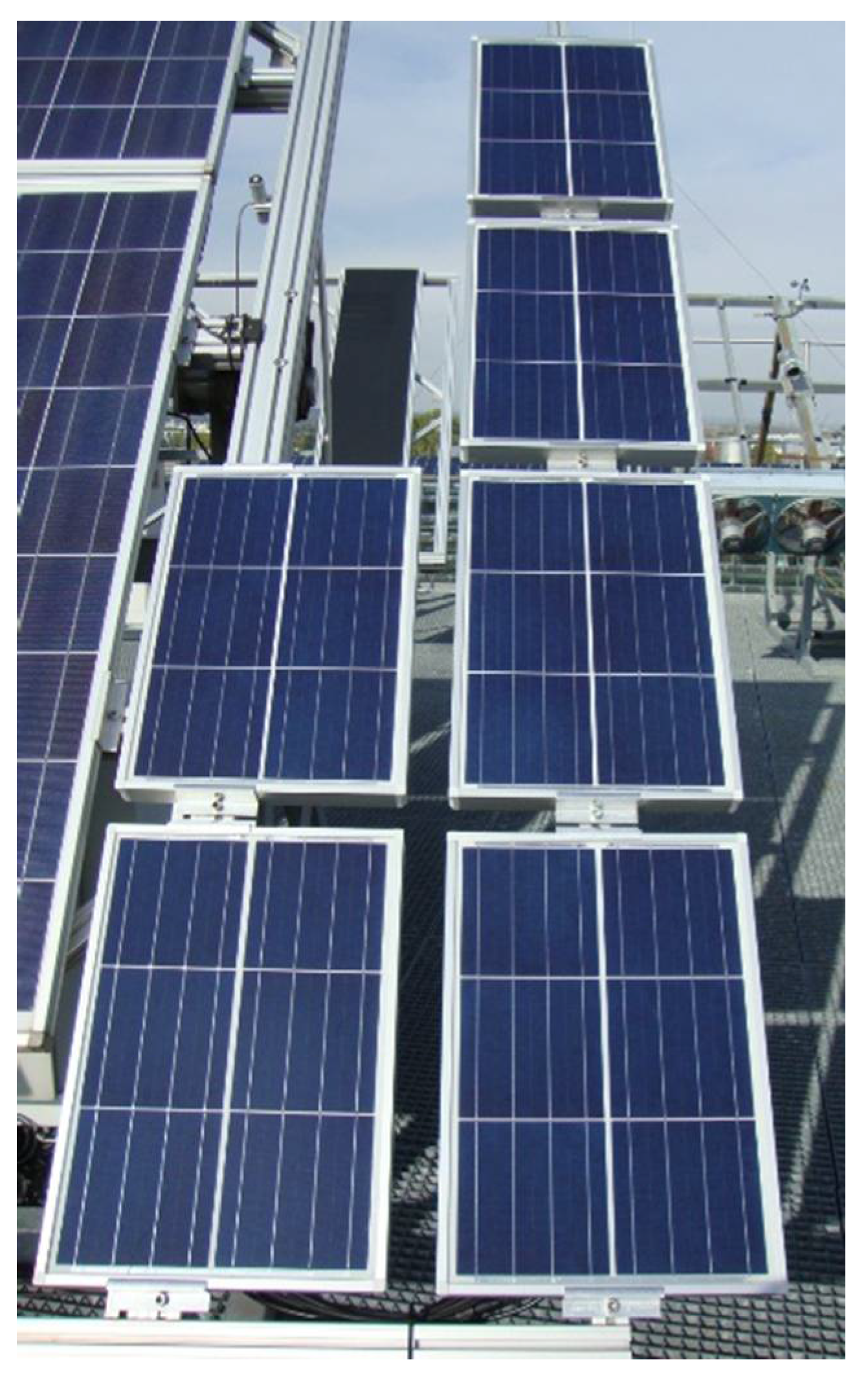
  • under outdoor (OD) conditions (in middle Europe, Vienna and Austria) for 1.5 years (see Figure 1).
All samples were characterized in detail (i) before and after light stabilization with 20 kWh and (iI) after the aging procedure with power and EL measurements. In addition, the effects of the failures on the formed fluorescence patterns of the polymeric encapsulant were monitored by measuring the UV-F of the test modules every 100 h during the accelerated aging tests (indoor) and every month during outdoor storage.

2.2. Characterisation Methods

2.2.1. Electrical Measurements

By means of IV measurements, the open circuit voltage (UOC), short circuit current (Isc), series resistance (RSER), shunt resistance (RSH), maximum power point (PMPP), voltage at PMPP (UMP), current at PMPP (IMP), and fill factor (FF) were determined. The IV measurements of all test modules before and after the accelerated ageing test or following natural weathering for 1.5 years were performed in accordance with IEC61215 [9,23]. The electrical performance was measured under laboratory standard conditions (25 °C; 1000 W/m2 with air mass (AM) 1.5 spectral distribution) using a PASAN HighLIGHT VLMT A+A+A+ flasher. The HighLIGHT VLMT (Very Large Module Tester) is designed to flash a surface of 3 m × 3 m. The accuracy of the power measurement is set by the quality and reliability of the module tester, with the used system being classified as A+A+A+ (according to the IEC Standard IEC 60904-9 [24]) based on three parameters: a spectral irradiance distribution of ≤12.5%, a non-uniformity of irradiance of 1% and a pulse instability (long term) of ≤1%.

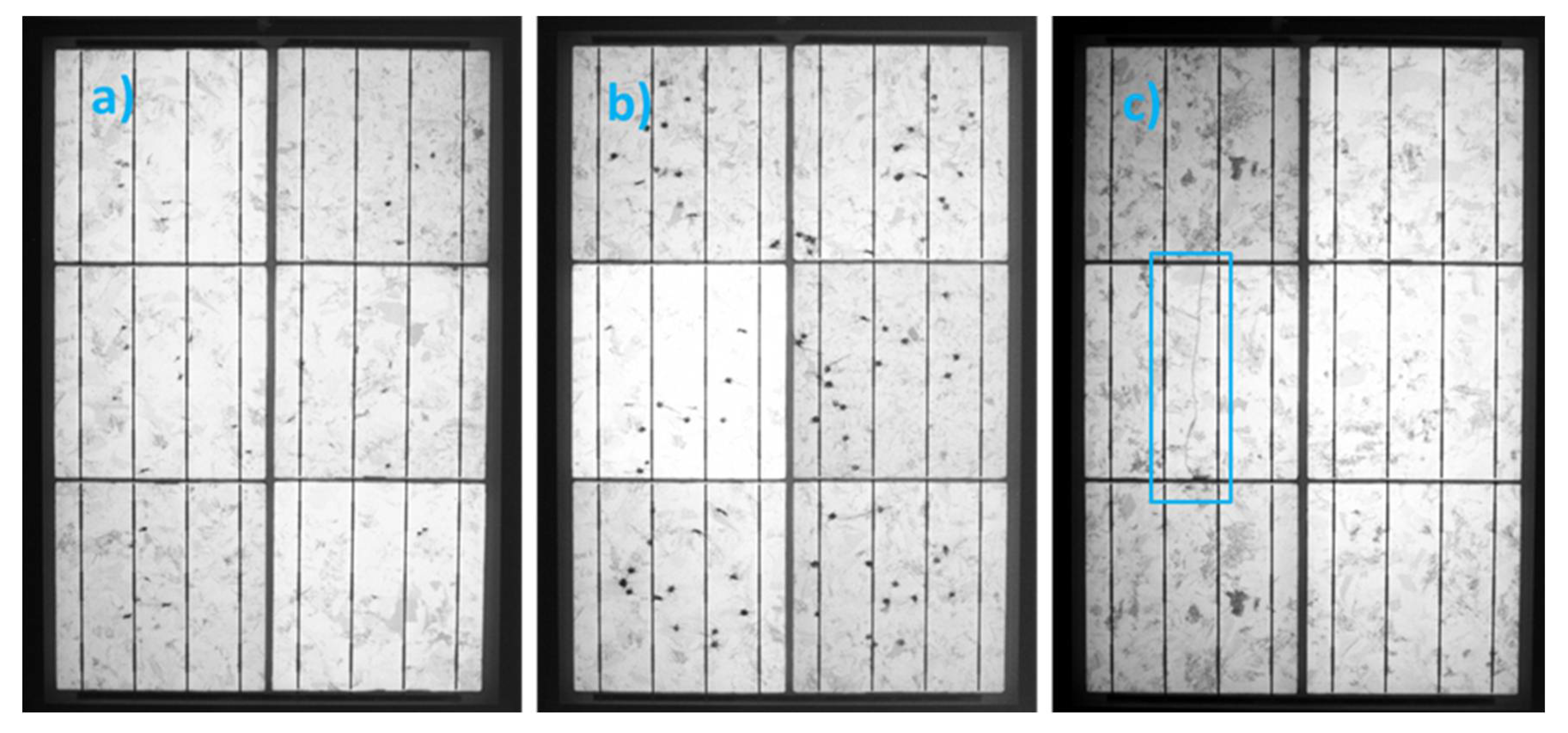
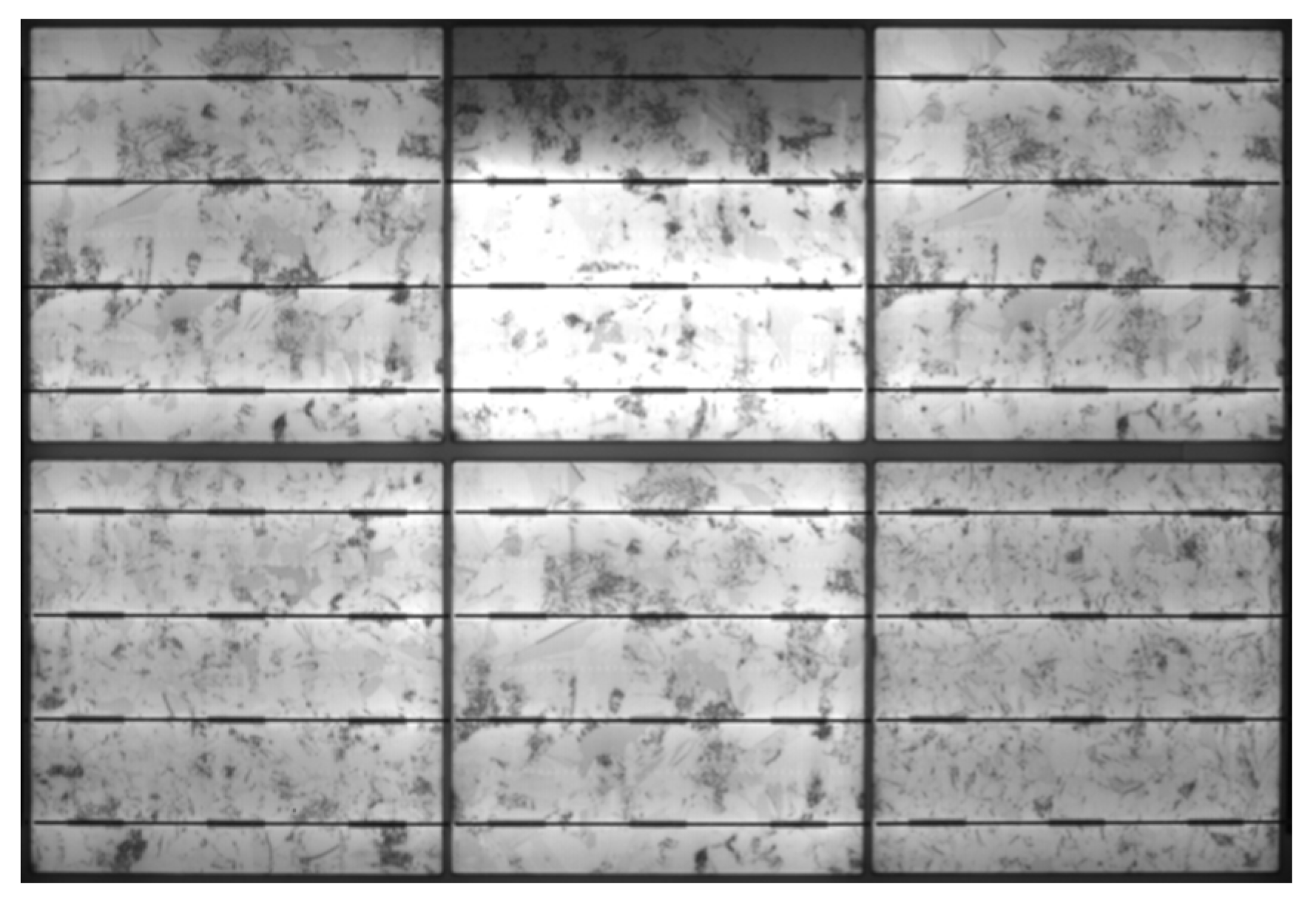
2.2.2. Electroluminescence Measurements

EL measurements take advantage of the radiative interband recombination of excited charge carriers in solar cells. For EL investigations, the module is operated as a light emitting diode. The emitted radiation due to recombination effects can be detected with a sensitive Si-CCD-camera. The wavelength window of the Si-CCD camera is 300 to 1100 nm. The solar cells are supplied with a defined external excitation current (current applied ≤ short circuit current (Isc) of the cell or module) while the camera takes an image of the emitted photons. Damaged areas of a solar module appear dark or radiate less than areas without defects. EL has proven to be a useful tool for investigating electrical inhomogeneities caused by intrinsic defects (e.g., grain boundaries, dislocations, shunts, or other process failures) and extrinsic defects (e.g., cell cracks, corrosion, or interrupted contacts) [25,26,27].
To determine the influences of defects (e.g., shunts), the EL behaviour of the test modules was investigated with different current densities: 10% and 100% of ISC. When applying a low current density (10% of Isc of the module), the conductivity of shunts was very high. When applying higher current densities (~ISC), the conductivity of the positive-negative (p-n)-junction increased compared to the shunt conductivity, and shunts were less influential on the EL intensity distribution. Thus, with low current densities, the material properties can be investigated, and with high current densities, the properties of the electrical contacts can be investigated [28].

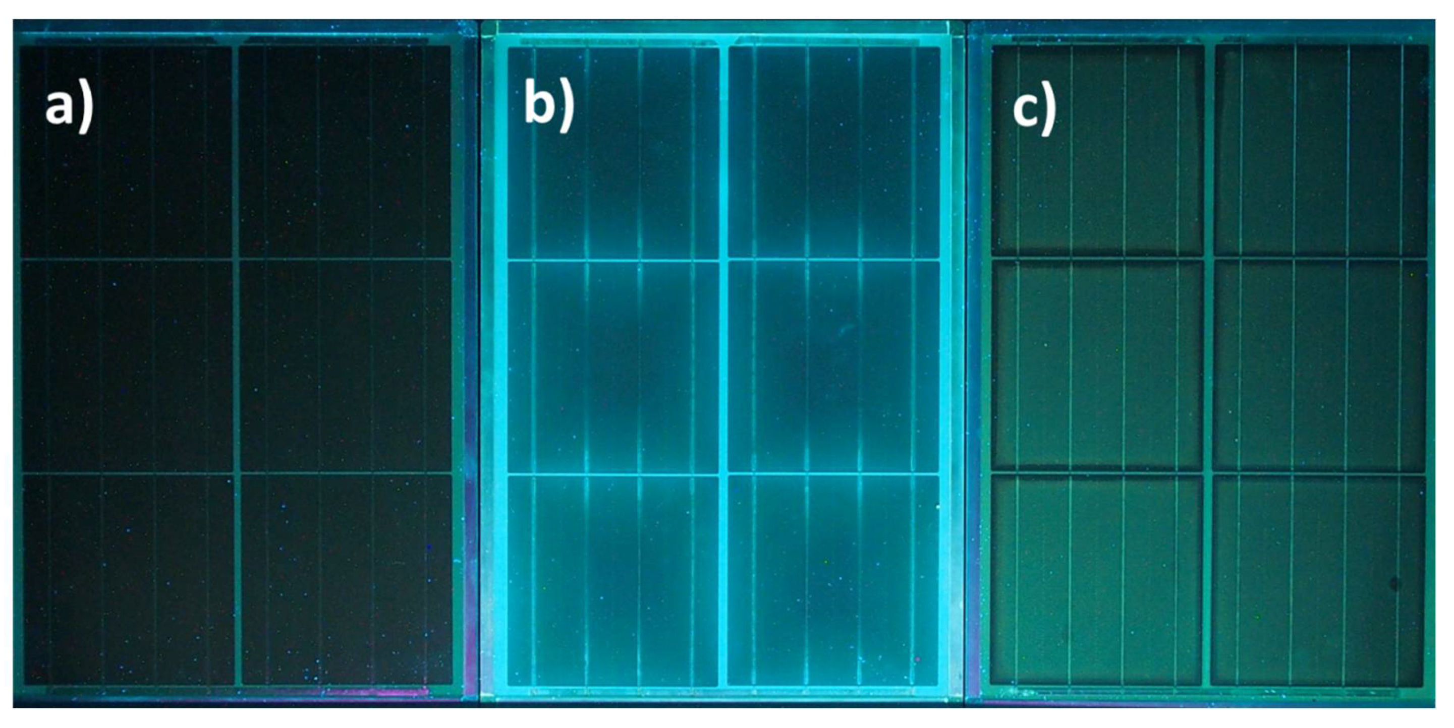
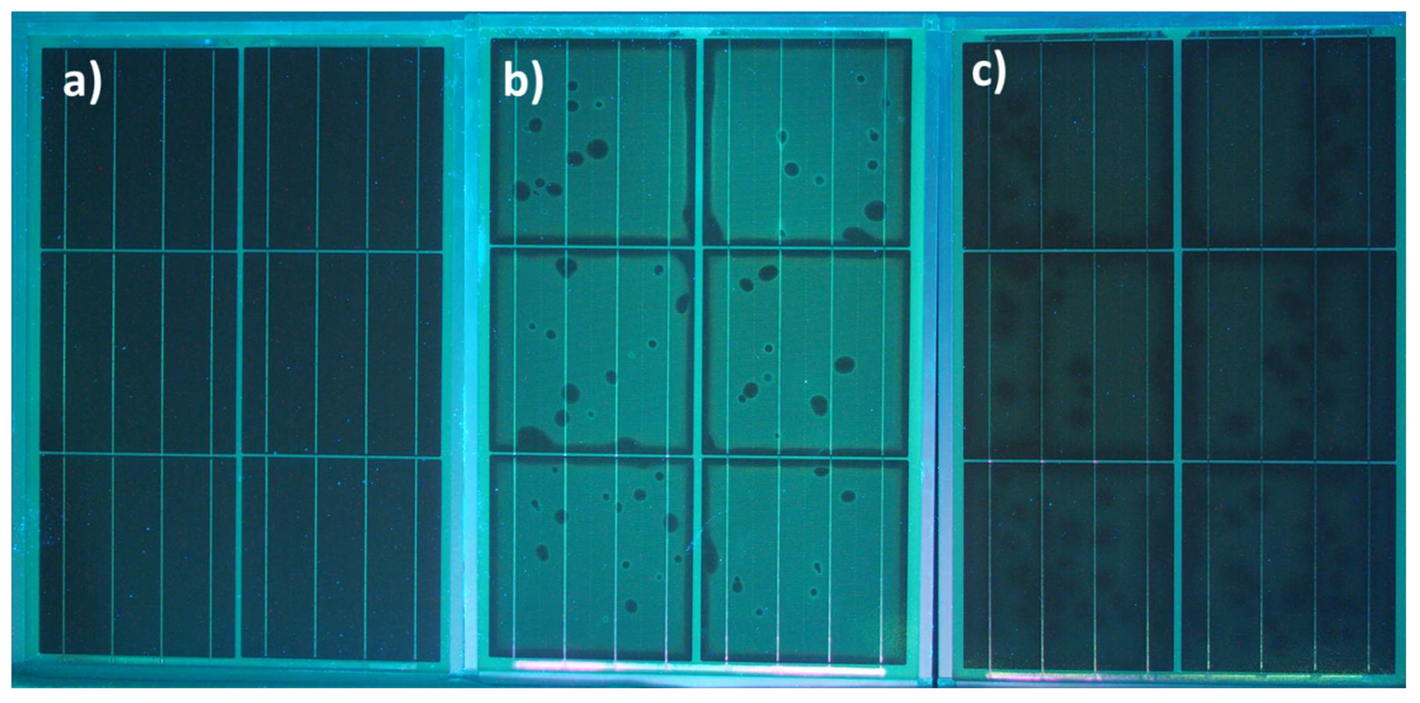
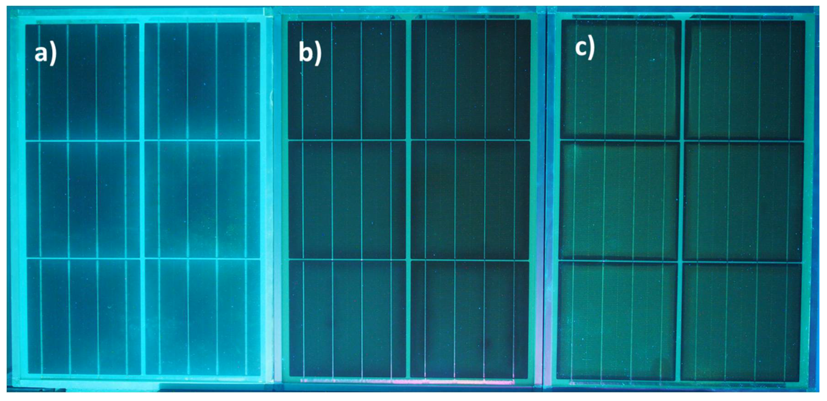
2.2.3. UV-Fluorescence Measurements

Fluorescence is a form of luminescence and stands for the physical effect of the emission of light by a material that has absorbed light or other electromagnetic radiation. The emitted light (e.g., in the visible region) has a longer wavelength than the absorbed radiation (e.g., UV light). A fluorophore is thus a fluorescent chemical compound that can re-emit light upon light excitation and mostly contains several combined aromatic groups or other plane or cyclic molecules with several π bonds. Typical fluorophores are degradation products of polymers and/or additives with chromophoric/fluorophoric groups. The fluorescence of materials can be extinguished by “photobleaching” effects which lead to a decrease in fluorescence due to reaction processes with, for example, oxygen [11,29,30]. The first description of fluoresence effects in PV encapsulants was performed in 1993 by Pern [31,32]. The use of this effect as a diagnosis tool for polymeric encapsulant processing and degradation was also reported be Pern et al. one year later [30]. The first to observe the UV fluorescing effects of PV encapsulants caused by ageing-induced polymer degradation was Röder et al. in 2008 [33,34,35,36,37,38], and the first to use these UV-F effects and the formation of specific patterns of fluorescing and bleached parts within the module to detect cell breakage of aged PV modules in the field was Köntges et al. in 2012 [14,39,40,41].
In this study, UV-Fluorescence measurements were performed in a dark environment by illumination of the PV modules with UV light and detection of the fluorescing light in the visible region by a photographic camera system (Olympus OM-D, equipped with high pass filter to cut off the UV irradiation). Excitation with UV light was performed with a self-made UV lamp [42] consisting of 3 power-tunable light emitting diode (LED) arrays with an emission maximum at 365 nm and a low pass filter to cut off all visible light. The power supply was a modified DC/DC converter with controllable and piecewise constant voltage/constant current characteristics, sourced by a 12-cell, lithium-polymer accumulator with a capacity of 5000 mAh. This characterization method is non-destructive, non-invasive, easy to handle and fast (an exposure time of 30 s is sufficient to achieve a well contrasted UV fluorescence image of a module) [17,22].

3. Results

In order to see (i) the effects that deliberately-generated failures (micro-cracks, cell cracks, glass breakage, and defects in the cell interconnection) have on developing UV fluorescence patterns and (ii) to determine whether propagation of such failures occurs with storage time, reference modules and defective test modules were treated in the same way (as described above).

3.1. Test Modules without Failures

As expected, the reference modules (test modules without failures) did not show relevant degradation effects, as determined by performance and EL measurements, irrespective of the stress conditions applied. The power of the modules after light stabilization was 24.3 ± 0.1 W under standard test conditions (STC) conditions (see Table 1) and changed only slightly upon accelerated and natural ageing. While irradiation with artificial sunlight for 1000 h caused a slight decrease in the power output (−1%) at the maximum power point (PMPP), storage under DH for 1000 h and OD storage for 1.5 years resulted in slight increases in the PMPP of +0.3% and +0.7%, respectively.
The original modules did not show any specific fluorescence behavior after manufacturing and light stabilization (see Figure 2a). Upon subsequent DH storage, however, the polymeric encapsulation showed fluorescing effects (Figure 2b). These effects were related to the ingress of water vapour into the polymeric encapsulant and were not homogeneously distributed over the whole module. The fluorescing effects were stronger above the backsheet and the rims of the cells. The broadness of the fluorescing rims increased with increasing storage time (related to water vapour permeating into the encapsulant via the polymeric backsheet).
In contrast, upon irradiation with artificial sunlight, fluorescing groups were formed within the front encapsulant layer of the module (Figure 2c). The UV-fluorescence was evenly distributed in the polymeric encapsulation and increased in intensity with increasing irradiation doses. In our test setup, after 300 h of irradiation in the accelerated ageing test and after 12 months of outdoor storage, UV-F effects could clearly be detected in the encapsulation of the test modules. Between and at the rims of the cells, the fluorescence was extinguished by oxygen (bleaching) permeating into the encapsulation via the polymeric backsheet. The broadness of the extinct area at the cell rims increased with increasing weathering time.
One testmodule showed a glass crack which occurred at the beginning of the irradiation test, most probably caused by thermal tension (untempered glass was used for all test modules). It was first noticed after 100 h storage time and increased in length, reaching its final magnitude after 400 h [8]. It was observed that the fluorescence formed homogeneously in the polymeric encapsulation over the cells and disappeared beneath the glass breakage after 300 h of further irradiation. The EL image showed that the glass breakage (induced by thermal stress in the first phase of the weathering test) did not cause a crack in the underlying cells. The disappearance of the fluorescence beneath the glass breakage is attributed to an oxygen bleaching effect. The incoming oxygen can interact/react with the activated and fluorescing sites of the polymer, leading to a decrease in its fluorescence intensity. The glass breakage had no impact on the performance of the test module after the 1000 h irradiation test.

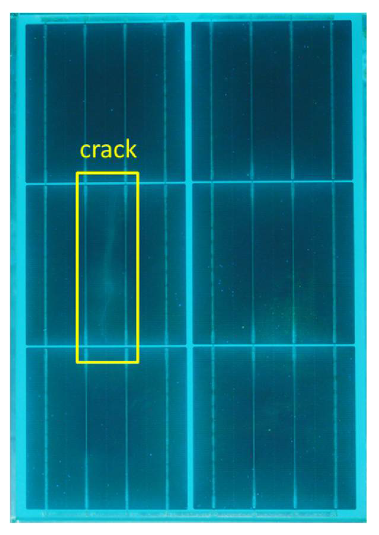
3.2. Test Modules with Cell Cracks/Micro-Cracks

The test module with deliberately induced cell cracks/micro-cracks did not show relevant differences in the power output (PMPP, measured under STC conditions) compared to the intact reference modules before ageing (see results in Table 2). Upon aging under irradiation, however, decreases in PMPP by −1.6% and −2.8% were observed, while storage under DH and outdoor conditions resulted in an increased electrical output of +1.1%and +1.9%, respectively.
It has to be noted at this point that it was very difficult to generate a comparable number and size of (micro)cracks in the six test modules. As visualized in the EL images (see Figure 3), there were modules with few (*) and numerous (**) micro-cracks and others with cell cracks (+), and it was expected that their effects on degradation would be quite different.
One test module (no. 1-14), which showed a cell crack in the EL image (Figure 3c), supplied UV-fluorescence images upon DH storage, as shown in Figure 4. In addition to the fluorescence formed with increasing storage time above the backsheet and the rims of the cells, fluorescence was also observed above the cell crack making it detectable for the observer. It has to be noted that neither the performance (−0.1%) nor the EL image of this test module were changed drastically upon artificial ageing for 1000 h DH. With one module (no. 1-09), the cell crack increased in length following outdoor storage for 1.5 years by a factor of 2, and the performance increased slightly (+1.1%).
Upon irradiation with artificial sunlight and natural sunlight (see Figure 5b,c), the evolving fluorescence pattern of the test modules with micro-cracks clearly differed from those of the test modules without failures (see Figure 2).
The UV-F images taken every 100 h of accelerated weathering again showed a continuous increase in the intensity of fluorescence above the cells with unequivocally detectable intensities starting from 300 h. However, there were numerous dark spots where no fluorescence was generated (Figure 5b). In comparison with the EL image of that module, a clear correlation with the positions of the micro-cracks in the cells could be obtained. At the positions of the micro-cracks in the cells, the fluorescence was extinguished by oxygen (bleaching) permeating into the front encapsulation via the polymeric backsheet and cell cracks. In the outdoor weathering, the effect of UV-F in the front encapsulant was clearly detectable after 1 year showing extinctions (dark spots) at the locations of the micro-cracks in the cells (see. Figure 5c; confirmed by parallel EL measurements).

3.3. Measurement of Test-Modules with Failures in the Connection System

The EL images of the test modules with defects in the connection system (interruption of one connection ribbon of one cell in the six-cell test module) all showed—as expected—a darker region of one cell, with the rest of the affected cell being brighter (see Figure 6). This effect was visible in the EL image in the original state, after accelerated ageing (under DH or irradiation conditions) and outdoor testing. The electrical performances of these test modules (PMPP, measured under STC- conditions) before and after ageing are summarized in Table 3. The power output of the original modules was only ~1% lower than that for the intact reference modules. This effect was due to a higher RSER.
Upon ageing, the test modules with a deliberately-generated connection defect behaved comparably to the intact modules (decrease in PMPP after artificial irradiation by −1.2%, stable after DH storage, slight increase upon OD testing by +0.7%), and no stress-induced propagation of the failures could be observed in the test program applied. The UV-F images of the test modules with defects in the cell interconnectors were identical to those of the intact reference modules, irrespective of the stress treatment (see Figure 7).
This comparison clearly shows that the UV-F pattern which appears under outdoor conditions (Figure 7b) resembles the fluorescence pattern observed after artificial aging (Figure 7c). However, the intensity of the UV-F above the cells is lower and the extinct area at the cell rims is broader, indicating a pronounced oxygen ingress.

4. Discussion

The results presented show a good robustness of the PV modules against stress, even when defects such as micro-cracks, cell cracks, glass breakage or interruptions in the cell interconnections are present. Hardly any propagation of the module failures in the accelerated ageing tests (indoors) and the outdoor exposure test could be detected. It was also noticed that the length of the micro-cracks (as visualized by the EL-images) did not (or only minor) increase during the time span of the accelerated (indoor) or natural ageing (outdoor) tests performed within the work presented. These effects were also found by Buerhop-Lutz et al. in indoor tests [15] and Jaeckel et al. in a 15-year outdoor test [16] and are in accordance with a recent study by Dimish et al. on the impact of cracks on photovoltaic power performance [43].
However, the presence of numerous micro-cracks led to a higher rate of degradation; the power loss upon irradiation (1000 W/m2 for 1000 h) was twice as high as that for the intact reference module under the same stress conditions. Defects in the cell interconnection of test modules caused a higher series resistance, leading to a slightly lower power output by ~1%. The relative change in power upon accelerated ageing, though, was not affected by that failure. Outdoor weathering for 1.5 years did not lead to any degradation effects, irrespective of the failures deliberately incorporated in the test modules.
In the unaged state, the polymeric encapsulates of the PV modules (ethylene-vinyl acetate, EVA) did not show distinctive fluorescence. The EVA polymer itself has no fluorescing groups in its original state but UV-excitable fluorophores/chromophores can be formed from the peroxidic curing agent/crosslinker during curing, either as decomposition product [29] or by degradation of stabilizers by peroxides [44,45]. Furthermore, constituents of the encapsulating material, like impurities or additives, also influence the UV-F of the encapsulating polymer [46,47,48]. With an increasing lifetime, the encapsulant material degraded due to the interaction with irradiation through artificial or natural sunlight and the elevated temperature from forming fluorophores. The fluorescing effect was increasing with exposure time as it is directly dependent on the concentration of fluorophores built [1]. Partially activated and degraded polymer chains show fluorescence effects [48]. As the encapsulant not only comprises the polymeric base material itself but also of a mixture of additives, its composition has an influence on the development of the fluorescence (as studied in detailed by Peike et al. [46,48]), [29].
Our own results as well as detailed studies by Schlothauer et al. [47,49] confirm that in the photobleached areas, the polymeric encapsulant is chemically changed due to the oxidative reaction of the polymer, leading to chain scission and consequently, to changes in the viscoelastic mechanical properties and thermomechanical properties of the polymer.
Comparable fluorescence patterns of the front encapsulant of the test modules were observed following artificial and natural sunlight weathering. However, during outdoor exposure, the fluorescence effects were clearly detectable in the field (in darkness) with a UV-F lamp after ~1 year. This is in good agreement with findings reported in the literature regarding an induction period for the visible detection of UV-fluorescence [25]. Köntges et al. reported [11] that the module should have been exposed to UV dose of approximately 80 kWh/m², which correlates to about 1.5 years of outdoor exposure in Germany, to get a sufficient fluorescence signal. The formation of the fluorescing groups in the polymer requires irradiation and the absence of oxygen; an elevated temperature accelerates the process. Thus, in the artificial weathering test (1000 W/m2 of simulated sunlight with metal halide lamps (300–2500 nm) performed at a chamber temperature of 50 °C with 40% r.H. for 1000 h), UV-F patterns were already detectable after 300 h.
The abovementioned fluorescence patterns formed in the polymeric encapsulant upon weathering/irradiation can become extinct in the presence of oxygen and irradiation. The permeation of oxygen into the encapsulant via glass breakage or a polymeric backsheet acts as bleaching agent for fluorescence. As the oxygen molecules can interact/react with the activated and fluorescing sites of the polymer, their presence leads to an irreversible decrease in the fluorescence intensity. Bleaching needs irradiation besides oxygen (“photobleaching”) [11,29,30]. The width of the bleached rim around the cell and the bleached area above the cell crack increased with time and were correlated with the permeation rate of oxygen into the front encapsulant [47,50,51].
This clearly indicates that UV-F imaging is a suitable tool, not only for detecting cell cracks in operating PV modules but also to allow for estimation of the timescale at when these cell cracks were generated. This may be of special interest to allow one to distinguish between installation- or transport-induced cell cracks and those which are generated during operation by, for example, a heavy hail storm [17]. Furthermore, the temperature-induced degradation effects of the encapsulant lead to increased fluorescing light intensities and make hot spots or overheated module parts visible in the UV-F images [11].
The fluorescence effects observed upon DH storage (high temperature, high humidity, no irradiation) above permeable backsheets were correlated with the ingress of water vapour [34,35,36,51,52] and its interaction with the polymeric encapsulant and had a different origin from the irradiation-induced fluorescence effects [22,49,50,51]. The intensity of this type of fluorescence is lower, and fluorescence spectroscopic measurements have shown that the absorption maximum of elevated temperature and water induced fluorescence lies at a lower wavelength than for irradiation induced fluorescence, as described in detail by Röder and Schlothauer in several scientific presentations [33,36,45,50,53].

5. Conclusions

The performances of PV modules with mechanical module failures, such as micro-cracks, cell cracks, glass breakage or breakage of interconnectors were found to be rather unaffected upon storage under various stress conditions. In most cases, no propagation of the module failures in the accelerated ageing tests and the outdoor exposure test could be detected. However, the presence of numerous micro-cracks led to a higher rate of degradation; the power loss upon irradiation was twice as high as for the intact reference module upon accelerated ageing.
UV-F imaging is a perfect tool for on-site detection of module failures connected with a mechanical rupture of the solar cells and additionally, gives information about the timescale of the formation of the cracks. The induction period for the fluorescence effects of the polymeric encapsulant is ~1 year of outdoor weathering (in middle Europe) and 300 h of artificial irradiation (with 1000 W/m2 artificial sunlight 300–2500 nm). Characteristic fluorescence patterns and types are formed upon temperature and humidity impact (DH storage) and irradiation stress (artificial weathering and outdoor exposure). Mechanical failures of the modules, such as cell cracks and glass breakage have strong influences on the local extinction of the fluorescence (photo bleaching).

Author Contributions

All authors are participants of the research project INFINITY.

Acknowledgments

This work was conducted as part of the Austrian “Energy Research Program” project INFINITY. This project is funded by the Austrian Climate and Energy Fond and the Austrian Research Promotion Agency (FFG) which are gratefully acknowledged.

Conflicts of Interest

The authors declare no conflict of interest.

References

  1. Masson, G.; Kaizuka, I.; International Energy Agency; Photovoltaic Power Systems Programme (Eds.) Report IEA PVPS T1-32:2017: Trends 2017 in Photovoltaic Applications; IRENA and IEA PVPS: St. Ursen, Switzerland, 2017; ISBN 978-3-906042-68-8. [Google Scholar]
  2. Solar Power Europe. Global Market Outlook 2017–2021. M. Schmela, SolarPower Europe. 2017. Available online: www.solarpowereurope.org (accessed on 1 May 2017).
  3. Liu, J.; Long, Y.; Song, X. A Study on the Conduction Mechanism and Evaluation of the Comprehensive Efficiency of Photovoltaic Power Generation in China. Energies 2017, 10, 723. [Google Scholar] [CrossRef]
  4. Weckend, S.; Wade, A.; Heath, G. (Eds.) End-of-Life Management: Solar Photovoltaic Panels; Joined Report IRENA/IEA-PVPS; IEA-PVPS Report Number: T12-06:2016; IRENA and IEA PVPS: St. Ursen, Switzerland, 2016; ISBN 978-92-95111-98-1. [Google Scholar]
  5. Gómez-Lorente, D.; Rabaza, O.; Aznar-Dols, F.; Mercado-Vargas, M.J. Economic and Environmental Study of Wineries Powered by Grid-Connected Photovoltaic Systems in Spain. Energies 2017, 10, 222. [Google Scholar] [CrossRef]
  6. D’Adamo, I.; Miliacca, M.; Rosa, P. Economic Feasibility for Recycling of Waste Crystalline Silicon Photovoltaic Modules. Int. J. Photoenergy 2017, 2017, 4184676. [Google Scholar] [CrossRef]
  7. Nordmann, T.; Clavadetscher, L.; van Sark, W.G.J.H.M.; Green, M.; International Energy Agency; Photovoltaic Power Systems Programme (Eds.) Report IEA-PVPS T13-05-2014: Analysis of Long-Term Performance of PV Systems; IRENA and IEA PVPS: St. Ursen, Switzerland, 2014; ISBN 978-3-906042-21-3. [Google Scholar]
  8. von Armansperg, M.; Oechslin, D.; Schweneke, M. (Eds.) Report of the EU-Project Solar Bankability: Technical Bankability Guidelines: Recommendations to Enhance Technical Quality of Existing and New PV Investments, EC Grant Agreement Number: No 649997. Available online: https://www.tuv.com/content-media-files/master-content/services/products/p06-solar/solar-downloadpage/solar-bankability_d4.3_technical-bankability-guidelines.pdf (accessed on 1 February 2017).
  9. Wohlgemuth, J. Standards for PV Modules and Components—Recent Developments and Challenges. In Proceedings of the 27th European PVSEC, Frankfurt, Germany, 24–28 September 2012. [Google Scholar]
  10. Dunlop, E.D. Lifetime performance of crystalline silicon PV modules. In Proceedings of the 3rd World Conference on Photovoltaic Energy Conversion, Osaka, Japan, 11–18 May 2003. [Google Scholar]
  11. Köntges, M.; Kurtz, S.; Packard, C.; Jahn, U.; Berger, K.A.; Kato, K.; Friesen, T.; Liu, H.; Van Iseghem, M.; International Energy Agency; et al. (Eds.) Report IEA-PVPS T13-01:2014: Review of Failures of PV Modules; IRENA and IEA PVPS: St. Ursen, Switzerland, 2014; ISBN 978-3-906042-16-9. [Google Scholar]
  12. Köntges, M.; Kunze, I.; Kajari-Schröder, S.; Breitenmoser, X.; Bjørneklett, B. Quantifying the Risk of Power Loss in PV Modules Due to Micro Cracks. In Proceedings of the 25th European PV SEC, 4BO.9.4, Valencia, Spain, 6–10 September 2010; pp. 3745–3752. [Google Scholar] [CrossRef]
  13. Köntges, M.; Kunze, I.; Kajari-Schröder, S.; Breitenmoser, X.; Bjørneklett, B. The risk of power loss in crystalline silicon based photovoltaic modules due to microcracks. Sol. Energy Mater. Sol. Cells 2011, 5, 1131–1137. [Google Scholar] [CrossRef]
  14. Köntges, M.; Kajari-Schröder, S.; Kunze, I. Crack Statistic for Wafer-Based Silicon Solar Cell Modules in the Field Measured by UV Fluorescence. IEEE J. Photovolt. 2013, 3, 95–101. [Google Scholar] [CrossRef]
  15. Buerhop-Lutz, C.; Winkler, T.; Fecher, F.W.; Bemm, A.; Hauch, J.; Camus, C.; Brabec, C.J. Performance Analysis of Pre-Cracked PV-Modules at Realistic Loading Conditions. In Proceedings of the 33rd European PV-SEC, 5CO.8.2, Amsterdam, The Netherlands, 25–29 September 2017; pp. 1451–1456. [Google Scholar] [CrossRef]
  16. Jaeckel, B.; Franke, T.; Arp, J. Long Term Statistics on Micro Cracks and Their Impact on Performance. In Proceedings of the 33rd European PV-SEC, 5CO5.6, Amsterdam, The Netherlands, 25–29 September 2017; pp. 1396–1401. [Google Scholar] [CrossRef]
  17. Mühleisen, W.; Eder, G.C.; Voronko, Y.; Spielberger, M.; Sonnleitner, H.; Knöbl, K.; Ebner, R.; Ujvari, G.; Hirschl, C. Outdoor detection and visualization of hailstorm damages of photovoltaic plants. Renew. Energy 2018, 118, 138–145. [Google Scholar] [CrossRef]
  18. Köntges, M.; Siebert, M.; Illing, R.; Wegert, F. Influence of Photovoltaic-Module Handling on Solar Cell Cracking. In Proceedings of the 30th European PV SEC, 5BO12.6, Kyoto, Japan, 23–27 November 2014; pp. 2276–2282. [Google Scholar] [CrossRef]
  19. Mathiak, G.; Pohl, L.; Sommer, J.; Fritzsche, U.; Herrmann, W.; Reil, F.; Althaus, J. PV Module Damages Caused by Hail Impact—Field Experience and Lab Tests. In Proceedings of the 31th European PV SEC, 5DO.12.5, Hamburg, Germany, 14–18 September 2015; pp. 1915–1919. [Google Scholar] [CrossRef]
  20. Köntges, M.; Oreski, G.; Jahn, U.; Herz, M.; Hacke, P.; Weiss, K.-A.; Razongles, G.; Paggi, M.; Parlevliet, D.; Tanahashi, T.; et al. (Eds.) Report IEA-PVPS T13-09:2017: Assessment of Photovoltaic Module Failures in the Field; IRENA and IEA PVPS: St. Ursen, Switzerland, 2017; ISBN 978-3-906042-54-1. [Google Scholar]
  21. Hirschl, C.; Mühleisen, W.; Brantegger, G.; Neumaier, L.; Spielberger, M.; Sonnleitner, H.; Kubicek, B.; Ujvari, G.; Ebner, R.; Schwark, M.; et al. Scientific and economic comparison of outdoor evaluation methods for photovoltaic power plants. Renew. Energy 2018. submitted. [Google Scholar]
  22. Hirschl, C.; Eder, G.C.; Neumaier, L.; Mühleisen, W.; Voronko, Y.; Ebner, R.; Kubicek, B.; Berger, K.A. Long term development of Photovoltaic module failures during accelerated ageing tests. In Proceedings of the 33rd European PV-SEC, 5BV.4.72, Amsterdam, The Netherlands, 25–29 September 2017; pp. 1709–1712. [Google Scholar] [CrossRef]
  23. International Standard IEC61215. Terrestrial Photovoltaic (PV) Modules—Design Qualification and Type Approval—Part 1: Test Requirements and—Part 2: Test Procedures, 1.0 ed.; TC 82—Solar Photovoltaic Energy Systems; IEC: Geneva, Switzerland, 9 March 2016. [Google Scholar]
  24. International Standards IEC 60904-9:2007. Photovoltaic Devices—Part 9: Solar Simulator Performance Requirements, 2.0 ed.; TC 82—Solar Photovoltaic Energy Systems; IEC: Geneva, Switzerland, 16 October 2007. [Google Scholar]
  25. Wang, G.; Gong, H.; Zhu, J. Failure analysis of dark cells detected by electroluminescence (EL). In Proceedings of the 28th European PVSEC 2014, 4AV.5.1, Paris, France, 30 September–4 October 2013; pp. 3173–3179. [Google Scholar] [CrossRef]
  26. Köntges, M.; Siebert, M.; Hinken, D.; Eitner, U.; Bothe, K.; Potthof, T. Quantitative analysis of PV-modules by electroluminescence images for quality control. In Proceedings of the 24th European PVSEC, 4CO.2.3, Hamburg, Germany, 21–25 September 2009; pp. 3226–3231. [Google Scholar] [CrossRef]
  27. Ebner, R.; Zamini, S.; Újvári, G. Defect Analysis of Different Photovoltaic Modules Using Electroluminescene (EL) and Infrared (IR)-Thermography. In Proceedings of the 25th European PVSEC 2010, 1DV.2.8, Valencia, Spain, 6–10 September 2010. [Google Scholar] [CrossRef]
  28. Crozier, J.L. Identifying voltage dependent features in photovoltaic modules using electroluminescence imaging. In Proceedings of the 29th EU-PVSEC, Amsterdam, The Netherlands, 22–26 September 2014. [Google Scholar]
  29. Pern, F.J. Factors that affect the EVA encapsulant discoloration rate upon accelerated exposure. Sol. Energy Mater. Sol. Cells 1996, 41–42, 587–615. [Google Scholar] [CrossRef]
  30. Pern, F.J.; Glick, S.H. Fluorescence analysis as a diagnostic tool for polymer encapsulation processing and degradation. AIP Conf. Proc. 1994, 306, 573–585. [Google Scholar] [CrossRef]
  31. Pern, F.J. Polymer encapsulants characterized by fluorescence analysis before and after degradation. In Proceedings of the Conference Record of the 23rd IEEE Photovoltaic Specialists Conference, Louisville, KY, USA, 10–14 May 1993. [Google Scholar] [CrossRef]
  32. Czanderna, A.W.; Pern, F.J. Encapsulation of PV modules using ethylene vinyl acetate copolymer as a pottant: A critical review. Sol. Energy Mater. Sol. Cells 1996, 43, 101–181. [Google Scholar] [CrossRef]
  33. Röder, B.; Ermilov, E.A.; Philipp, D.; Köhl, M. Observation of polymer degradation processes in photovoltaic modules via luminescence detection. In Reliability of Photovoltaic Cells, Modules, Components, and Systems; SPIE—The International Society for Optical Engineering: Bellingham, WA, USA, 2008; Volume 7048. [Google Scholar]
  34. Schlothauer, J.; Jungwirth, S.; Röder, B.; Köhl, M. Fluorescence imaging: A powerful tool for the investigation of polymer degradation in PV modules. Photovolt. Int. 2010, 10, 149–154. [Google Scholar]
  35. Jungwirth, S.; Röder, B.; Weiss, K.A.; Köhl, M. The influence of different back sheet materials on EVA degradation in photovoltaic modules investigated by luminescence detection. In SPIE Proceedings—Reliability of Photovoltaic Cells, Modules, Components, and Systems III; Dhere, N.G., Wohlgemuth, J.H., Lynn, K., Eds.; SPIE: Bellingham, WA, USA, 2010; Volume 7773, ISBN 9780819482693. [Google Scholar]
  36. Schlothauer, J.C.; Jungwirth, S.; Röder, B.; Köhl, M. Fluorescence imaging: A powerful tool for the investigation of polymer degradation in PV modules. In Proceedings of the 37th IEEE Photovoltaic Specialists Conference (PVSC), Seattle, WA, USA, 19–24 June 2011; pp. 003606–003608. [Google Scholar] [CrossRef]
  37. Röder, B.; Jungwirth, S.; Braune, M.; Philipp, D.; Köhl, M. The influence of different ageing factors on polymer degradation in photovoltaic modules investigated by luminescence detection. In SPIE Proceedings—Reliability of Photovoltaic Cells, Modules, Components, and Systems III; Dhere, N.G., Wohlgemuth, J.H., Lynn, K., Eds.; SPIE: Bellingham, WA, USA, 2010; Volume 7773, ISBN 9780819482693. [Google Scholar]
  38. Röder, B.; Schlothauer, J.; Jungwirth, S.; Köhl, M. Investigation of outdoor degradation of photovoltaic modules by luminescence and electroluminescence. In SPIE Proceedings—Reliability of Photovoltaic Cells, Modules, Components, and Systems III; Dhere, N.G., Wohlgemuth, J.H., Lynn, K., Eds.; SPIE: Bellingham, WA, USA, 2010; Volume 7773, ISBN 9780819482693. [Google Scholar]
  39. Morlier, A.; Siebert, M.; Kunze, I.; Mathiak, G.; Köntges, M. Detecting photovoltaic module failures in the field during daytime with ultraviolet fluorescence module inspection. In Proceedings of the 44th IEEE PVSC, Washington, DC, USA, 25–30 June 2017. [Google Scholar]
  40. Morlier, A.; Köntges, M.; Siebert, M.; Kunze, I. UV fluorescence imaging as fast inspection method for PV modules in the field. In Proceedings of the 14th IEA PVPS Task 13 Meeting, Bolzano, Italy, 3–8 April 2016. [Google Scholar]
  41. Köntges, M.; Kajari-Schröder, S.; Kunze, I. Cells Cracks Measured by UV Fluorescence in the Field. In Proceedings of the 27th European PVSEC, 4CO.11.4, Frankfurt, Germany, 24–28 September 2012; pp. 3033–3040. [Google Scholar] [CrossRef]
  42. Knöbl, K.; University of Applied Sciences, Technicum, Vienna, Austria. Personal communication, 2016.
  43. Dhimish, M.; Holmes, V.; Mehrdadi, B.; Dales, M. The impact of cracks on photovoltaic power performance. J. Sci. Adv. Mater. Dev. 2017, 2, 199–209. [Google Scholar] [CrossRef]
  44. Morlier, A.; Köntges, M.; Blankemeyer, S.; Kunze, I. Contact-free determination of ethylene vinyl acetate crosslinking in PV modules with fluorescence emission. Energy Procedia 2014, 55, 348–355. [Google Scholar] [CrossRef]
  45. Schlothauer, J.C.; Ralaiarisoa, R.M.; Morlier, A.; Köntges, M.; Röder, B. Determination of the cross-linking degree of commercial ethylene-vinyl-acetate polymer by luminescence spectroscopy. J. Polym. Res. 2014, 21, 457. [Google Scholar] [CrossRef]
  46. Peike, C.; Purschke, L.; Weiß, K.A.; Köhl, M.; Kempe, M. Towards the origin of photochemical EVA discoloration. In Proceedings of the 39th IEEE Photovoltaic Specialists Conference, PVSC 2013, Tampa, FL, USA, 16–21 June 2013; pp. 1579–1584. [Google Scholar] [CrossRef]
  47. Schlothauer, J.C.; Grabmayer, K.; Hintersteiner, I.; Wallner, G.M.; Röder, B. Non-destructive 2D-luminescence detection of EVA in aged PV modules: Correlation to calorimetric properties, additive distribution and a clue to aging parameters. Sol. Energy Mater. Sol. Cells 2017, 159, 307–317. [Google Scholar] [CrossRef]
  48. Beinert, A.; Peike, C.; Dürr, I.; Kempe, M.D.; Reiter, G.; Weiß, K.A. The influence of the additive composition on degradation induced changes in Polyethylene-co-vinyl-acetate during photochemical aging. In Proceedings of the 29th European PVSEC, 5BV.4.6, Amsterdam, The Netherlands, 22–26 September 2014; pp. 3126–3132. [Google Scholar] [CrossRef]
  49. Schlothauer, J.C.; Grabmayer, K.; Wallner, G.M.; Röder, B. Correlations of spatially resolved photoluminescence and viscoelastic mechanical properties of encapsulating EVA in differently aged PV modules. Prog. Photovolt. 2016, 24, 855–870. [Google Scholar] [CrossRef]
  50. Schlothauer, J.; Jungwirth, S.; Köhl, M.; Röder, B. Degradation of the encapsulant polymer in outdoor weathered photovoltaic modules: Spatially resolved inspection of EVA ageing by fluorescence and correlation to electroluminescence. Sol. Energy Mater. Sol. Cells 2012, 102, 75–85. [Google Scholar] [CrossRef]
  51. Eder, G.C.; Voronko, Y.; Grillberger, P.; Kubicek, B.; Knöblm, K. UV-Fluorescence measurements as tool for the detection of degradation effects in PV-modules. In Proceedings of the 8th European Weathering Symposium, Vienna, Austria, 20–22 September 2017; Gesellschaft für Umweltsimulation e.V. GUS: Pfinztal, Germany, 2017. [Google Scholar]
  52. Peike, C.; Kaltenbach, T.; Weiß, K.A.; Koehl, M. Indoor vs. outdoor aging—Polymer degradation in PV modules investigated by Raman spectroscopy. In Reliability of Photovoltaic Cells, Modules, Components, and Systems V; SPIE—The International Society for Optical Engineering: Bellingham, WA, USA, 2012; Volume 8472. [Google Scholar] [CrossRef]
  53. Röder, B.; Schlothauer, J.; Köhl, M. Luminescence spectroscopy as powerful tool for non destructive inspection of PV module encapsulants. In Proceedings of the 5th Sophia Workshop PV Module Reliability, Loughborough, UK, 16–17 April 2015. [Google Scholar]
Figure 1. Outdoor test stand (Austrian Institute of Technology (AIT), Vienna, Austria).
Energies 11 01053 g001
Figure 2. UV-F images of three test modules: (a) one in the original state (stabilized); (b) one after storage under DH -conditions for 2000 h; and (c) one after exposition to artificial sunlight (1000 W/m2) for 1000 h.
Energies 11 01053 g002
Figure 3. Electroluminescence (EL) images at 10% short circuit current (ISC) of trhee test modules with (a) few (*) or (b) numerous (**) micro-cracks or (c) with a cell crack (+).
Energies 11 01053 g003
Figure 4. UV-F image of test module no. 1-14 after 2000 h DH showing a cell crack.
Energies 11 01053 g004
Figure 5. UV-F images of three test modules with micro-cracks: (a) one in the original state (stabilized); (b) one after exposition to artificial sunlight (1000 W/m2) for 1000 h; and (c) one after natural storage for 1.5 years.
Energies 11 01053 g005
Figure 6. EL image at 100% ISC of a test module with a defective cell interconnection in the original state.
Energies 11 01053 g006
Figure 7. UV-F images of three test modules with interconnector defects: (a) one after DH storage for 2000 h; (b) one after natural weathering outdoors for 1.5 years; and (c) one after indoor exposition to artificial sunlight (1000 W/m2) for 1000 h.
Energies 11 01053 g007
Table 1. Power output in [W] at the maximum power point (PMPP) (measured under standard test conditions) of the test modules without defects, before and after ageing.
Module NumberOriginal 1After 1000 h Artificial Irradiation (I)After 1000 h Damp Heat (DH)After 1.5 Years Outdoors (OD)
1-0124.3924.19
1-0624.4524.17
1-0324.29 24.33
1-0424.27 24.37
1-0224.44 24.61
1-2024.32 24.47
1 Values after light stabilization with 20 kWh.
Table 2. Power output in [W] at PMPP (measured under STC conditions) of the test modules with few * and numerous ** micro-cracks or a cell crack + before and after ageing.
Module NumberOriginal 1After 1000 h IAfter 1000 h DHAfter 1.5 Years OD
1-13 *24.4024.01
1-16 **24.4023.72
1-14 +24.42 24.39
1-15 *24.58 24.53
1-09 +24.32 24.77
1-19 **23.73 23.99
1 Values after light stabilization with 20 kWh.
Table 3. Power output in [W] at PMPP (measured under STC conditions) of the test modules with defects in the cell interconnection system before and after ageing.
Module NumberOriginal 1After 1000 h IAfter 1000 h DHAfter 1.5 Years OD
2-0524.1923.90
2-0624.2623.94
2-0324.12 24.13
2-0424.13 24.15
2-0923.99 24.13
2-1024.07 24.24
1 Values after light stabilization with 20 kWh.

