Article

A Fast Equalizer with Adaptive Balancing Current Control

1
Department of Electrical Engineering, Lunghwa University of Science and Technology (LHU), No. 300, Sec.1, Wanshou Road, Guishan District, Taoyuan City 33306, Taiwan
2
Department of Electrical Engineering, National Taiwan University of Science and Technology (NTUST), No. 43, Sec. 4, Keelung Road, Taipei 106, Taiwan
*
Author to whom correspondence should be addressed.
Energies 2018, 11(5), 1052; https://doi.org/10.3390/en11051052
Submission received: 16 March 2018 / Revised: 12 April 2018 / Accepted: 12 April 2018 / Published: 25 April 2018
(This article belongs to the Special Issue Battery Storage Technology for a Sustainable Future)

Abstract

:
In this paper, a fast equalizer for series-connected battery packs with adaptive balancing current control is proposed. As the duty cycle of the power switch in conventional equalizers is kept constant during the equalization process, smaller voltage difference between cells will decrease balancing current and consequently result in extended balancing time, especially in the later phase of equalization. To deal with this problem and take the battery nonlinearity and circuit parameter non-ideality into consideration, an adaptive balancing current control based on a fuzzy logic inference is proposed. The presented approach can adjust the duty ratio adaptively, according to voltages of individual cells and pack, to keep the balancing current nearly constant: Therefore, the balancing time can be shortened and the balancing efficiency can be improved. Finally, experimental results of three compared methods will be given and discussed to validate the feasibility, effectiveness, and performance improvement of the studied method.

1. Introduction

Energy storage systems consist of series-connected batteries have been widely applied to electric vehicles, renewable energy systems, and uninterruptible power supplies to meet the requirements of high voltage and/or high power [1,2,3,4,5,6]. A high-end battery energy storage system should be equipped with three functionalities, including battery protection, battery management, and battery equalization. Among them, the battery equalizer in particular dominates the battery lifespan. The reason is that the characteristics of individual cells in a battery string could be discrepant, due to the inevitable inconsistency in electrochemical properties from manufacturing process, ambient temperature variation during charging and discharging, and asymmetrical degradation with aging [7,8]. Accordingly, the cell voltages through the entire pack are inhomogeneous during the charging and discharging cycles. In order to guarantee a safe operating condition and prolong the battery longevity, the battery equalizer is essential for a series-connected battery pack to diminish the unbalanced charge phenomena, extend the pack available lifespan, and improve the overall performance.
Numerous equalization topologies [9,10,11,12] and control algorithms [13,14,15,16] have been proposed in the literature [17,18]. Among them, active balancing methods are fast and efficient compared with passive balancing methods. Active balancing can be classified into cell bypass [19], cell-to-cell, cell-to-pack, pack-to-cell, and cell-to-pack-to-cell balancing schemes. Owing to the fact that the voltage difference between cells is small, the balancing current is also small for the adjacent cell-to-cell and direct cell-to-cell methods, leading to a low balancing speed [20,21,22]. For the cell-to-pack [23,24] and pack-to-cell [25,26,27] methods, a large balancing current can be obtained due to the large voltage difference between the pack and individual cell. However, only one cell which has the highest/lowest voltage can deliver/receive the energy to/from the battery pack. Energy can be transferred directly from any cell to any other cell through the cell-to-pack-to-cell methods [28,29,30]. High balancing efficiency and speed can be achieved by these methods, at the cost of bulky size and high control complexity. On the other hand, the implementation methods for active equalizers include capacitive, inductive, and transformer-isolated types. The switched capacitor equalizer [31,32,33] transfers the charge using a regular switching operation. Its architecture is simple and its control complexity is low. However, the balancing current becomes small in the later phase of the equalization process, because the voltage differences between the cells become small. This results in a relatively long balancing time. The inductor-based equalizer can maintain the balancing current to avoid the problem of decreasing current later in the equalization period [11,34]. To achieve this goal, a close-loop current control should be implemented. The transformer-isolated equalizer, including multi-transformer [28] and multi-secondary-winding [29] topologies, can equalize multiple cells in the same balancing period: However, the winding number is proportional to the number of series-connected batteries. Hence these topologies are not suitable for large battery packs. Finally, the modularization concept can be utilized to deal with a high number of series-connected batteries packs [8,26,27,30,34,35].
In this paper, a fuzzy-logic-control-based fast equalizer for series-connected battery packs with constant current balancing mechanisms was studied. The power converter topology utilized in the proposed equalizer is a bidirectional flyback converter. In order to cope with the problem of balancing current reduction in the later equalization stage and take the battery nonlinearity and circuit parameter non-ideality into consideration, an adaptive balancing current control based on a fuzzy logic inference is proposed. The presented control algorithm can regulate the duty ratio adaptively, according to cell and pack voltages, to keep the balancing current nearly constant, which consequently shortens the balancing time and improves the balancing efficiency. Experimental results will then be provided, and comparisons with those obtained from conventional counterparts will also be given and summarized to confirm the feasibility, effectiveness, and performance improvement of the devised scheme. The main contributions of this paper are that the proposed equalizer can control and maintain the balancing current adaptively throughout the balancing process to accelerate the equalization speed. Moreover, fuzzy logic control (FLC) is employed to deal with the non-ideality and nonlinearity problem. Hence, an accurate battery and circuit model is not needed. In addition, a low-cost microcontroller unit (MCU) can be utilized to implement the devised equalizer and it is easy to be modularized to equalize a long battery string.

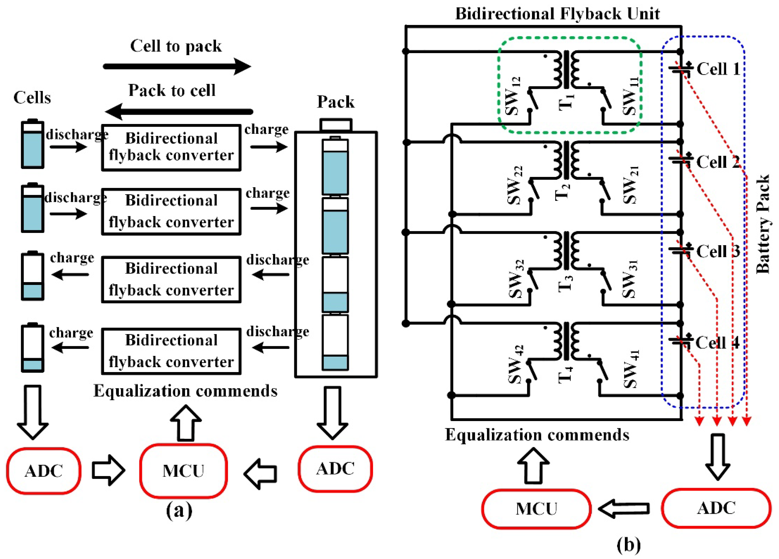
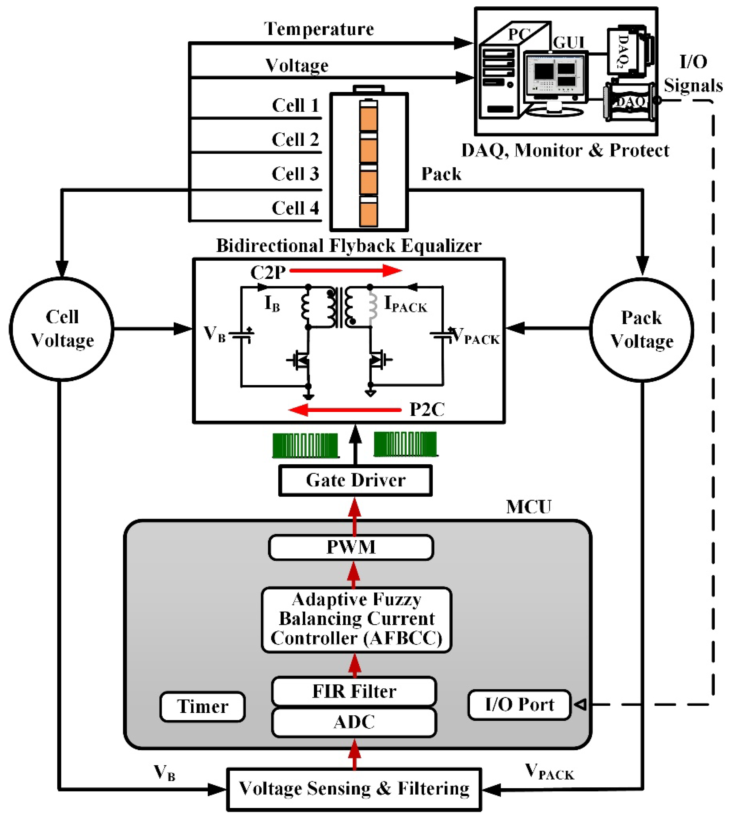
2. Equalizer Architecture and Operating Principle

Figure 1 shows the architecture of the utilized isolated bidirectional flyback converter [22,35]. From Figure 1, the secondary-side diode of the conventional flyback converter is replaced with an active switch to achieve bidirectional charge transfer. Thereby, the energy in the primary side battery cell can be transferred to the secondary side battery pack, and vice versa.
The operating principle of the bidirectional flyback converter can be divided into cell-to-pack (C2P) mode and pack-to-cell (P2C) mode. It is described as follows:
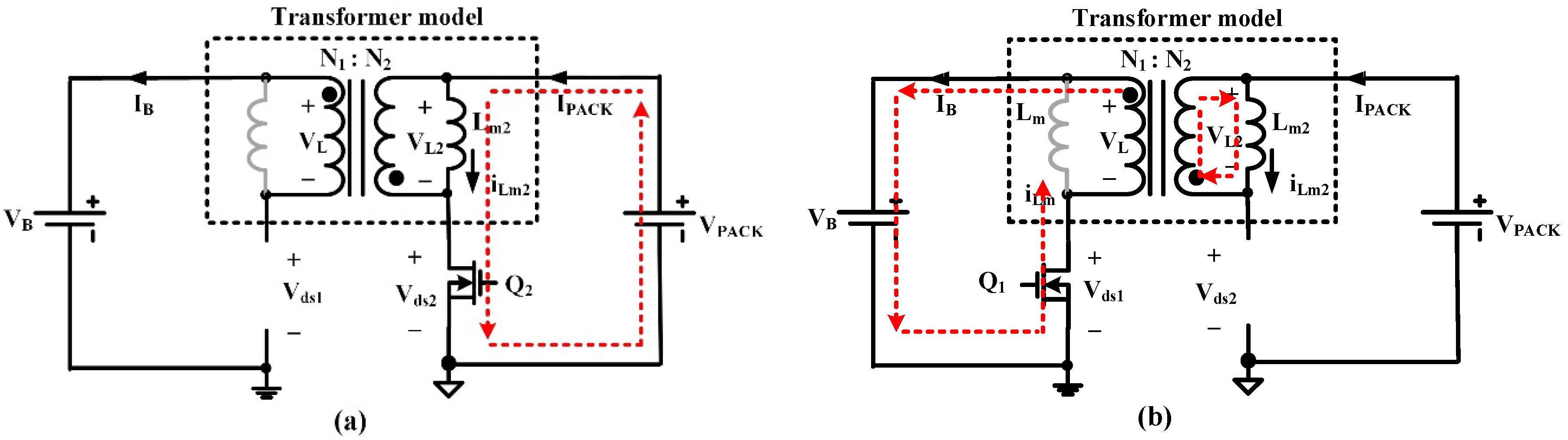
  • C2P mode: when the voltage of any individual cell is higher than the averaged voltage of the whole pack, C2P mode is chosen. As shown in Figure 2a, in subinterval 1, the switch Q1 is turned on and Q2 is turned off. The cell energy is stored in the magnetization inductor Lm. In subinterval 2, the switch Q2 is turned on and Q1 is turned off as shown in Figure 2b. At this time, the energy stored in the magnetization inductor is transferred to the secondary winding to charge the battery pack.
  • P2C mode: when the voltage of any individual cell is lower than the averaged voltage of the whole pack, P2C mode is adopted. As shown in Figure 3a, in the subinterval one, the switch Q2 is turned on and Q1 is turned off. The pack energizes the magnetization inductor Lm2. In subinterval two, as shown in Figure 3b, the switch Q1 is turned on and Q2 is turned off. At this time, the energy stored in the magnetization inductor is delivered to the primary winding to charge the cell.
Figure 4a shows a conceptual diagram of the proposed equalizer for a battery pack with four cells in series. If the controller detects that some of cells’ voltage were above the average value, the corresponding power converter will enter the C2P mode. On the contrary, P2C mode will be chosen if the cell voltage is below average value. In this way, cells with higher capacity will deliver energy to the battery pack and cells with lower capacity will receive energy from the battery pack. Figure 4b shows the practical wiring for the proposed equalizer with four cells in series.

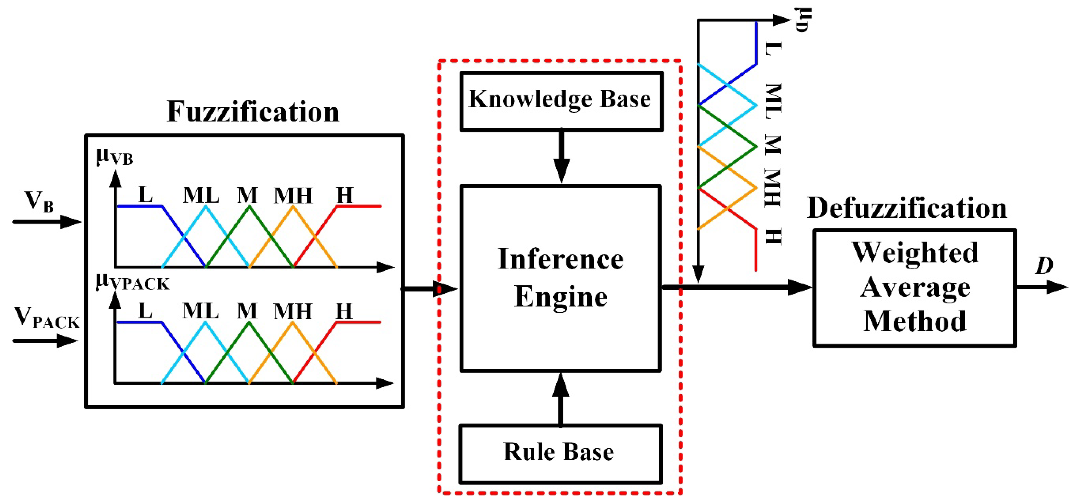
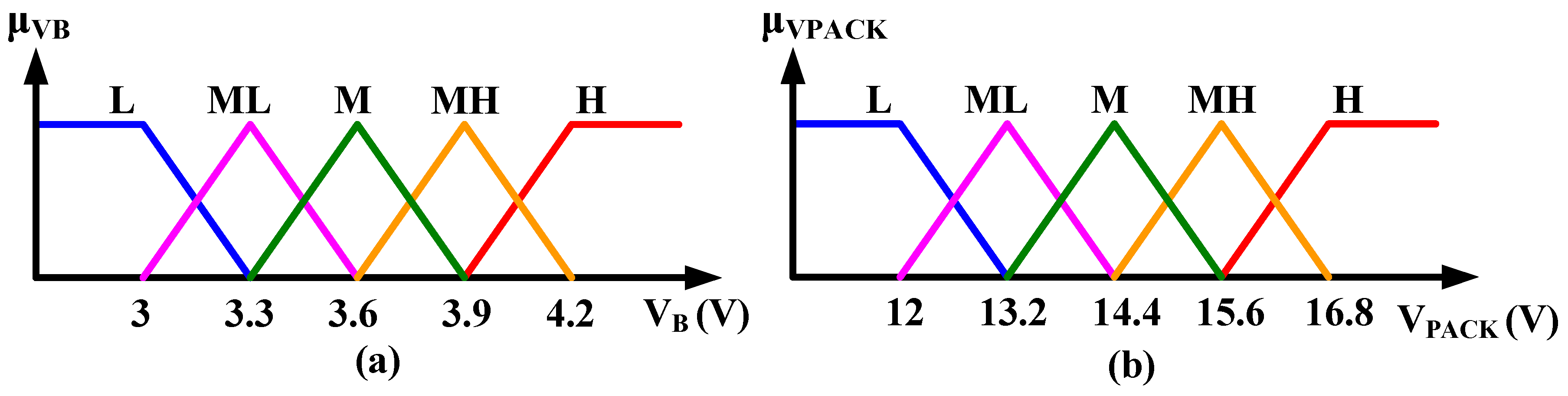
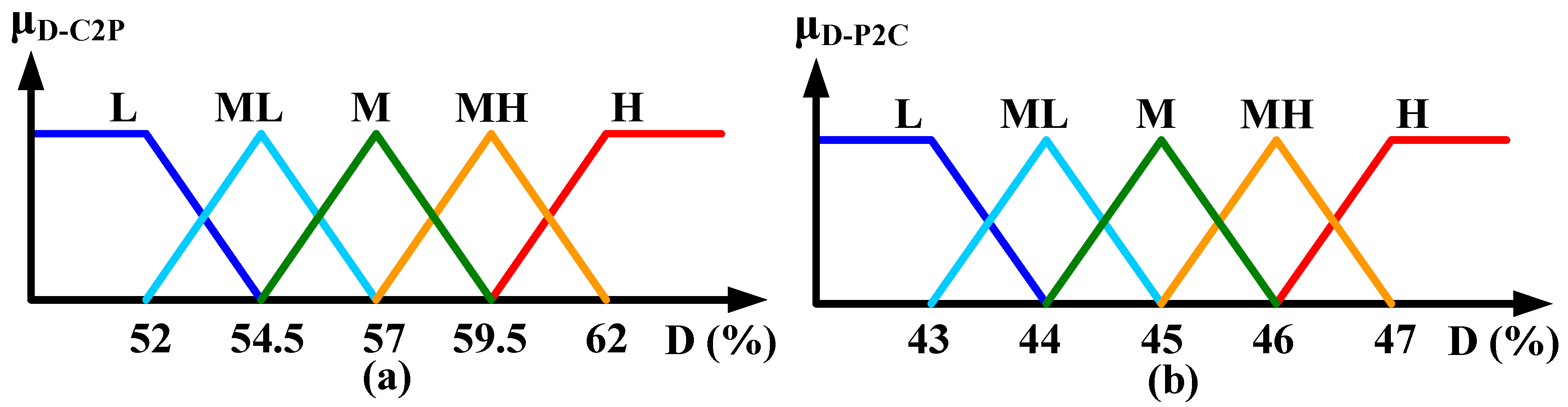
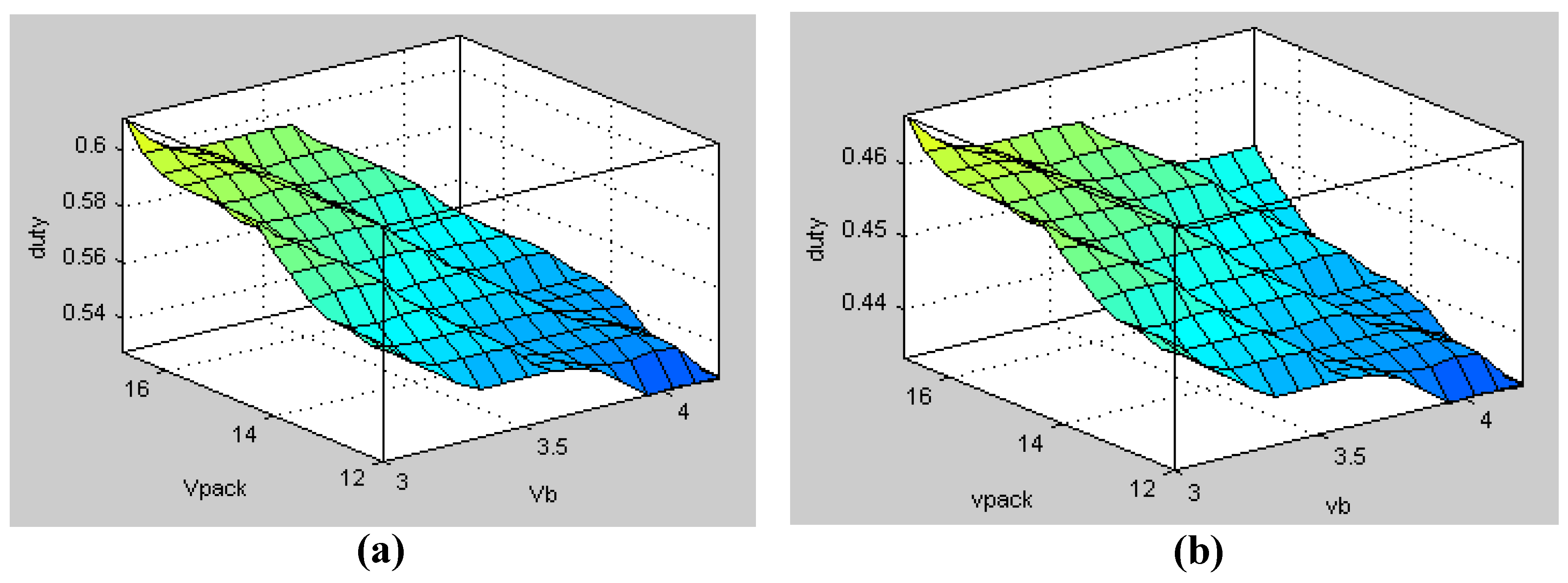
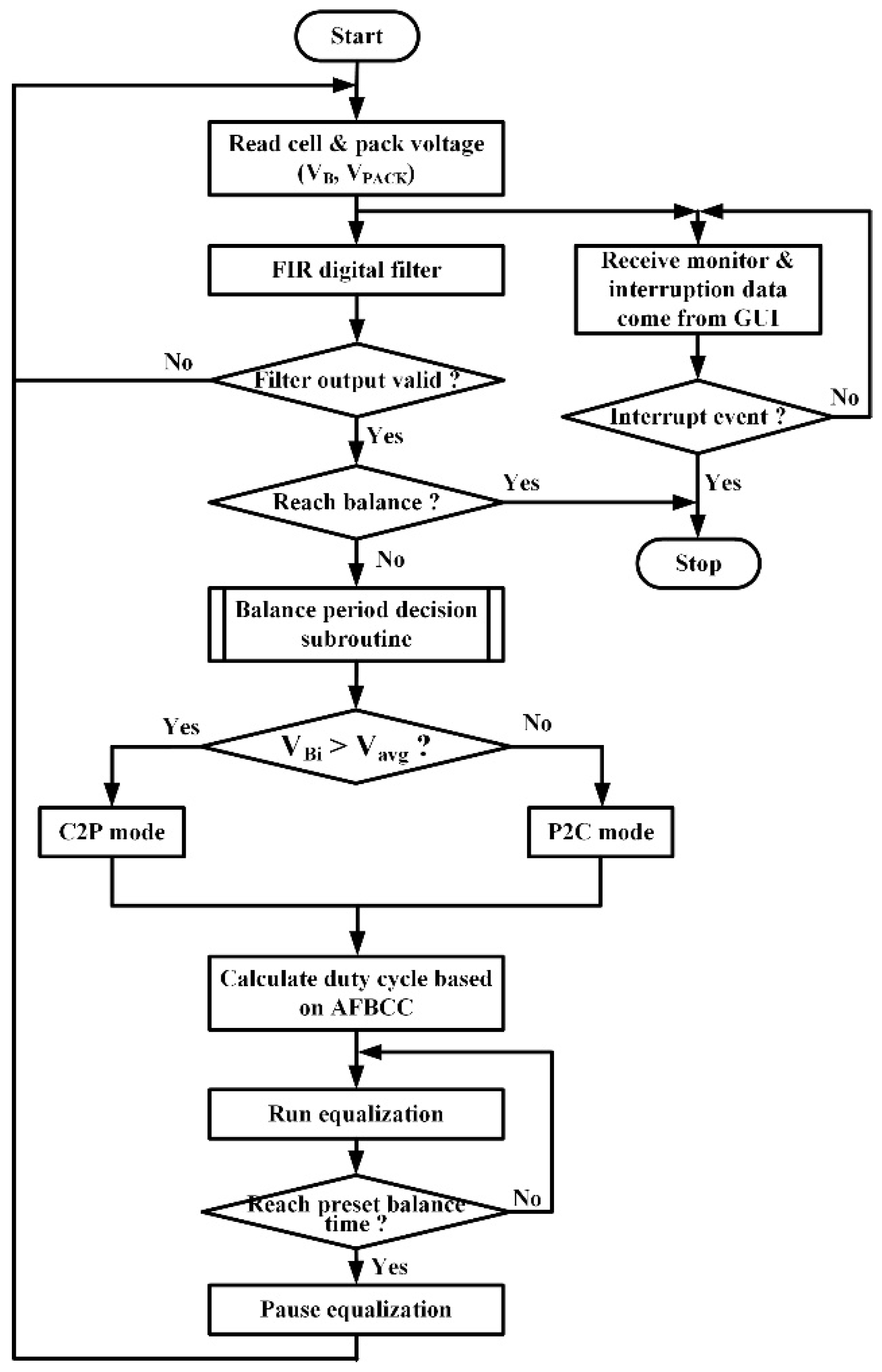
3. Adaptive Fuzzy-Logic-Based Balancing Current Control

A. Basic Concept
Conventional battery equalizers generally perform the equalization with a fixed duty cycle (FDC) [5,8,9,10,14,15,16,22,23,26,27,28,29,30,31,32,33,35]. However, when the voltage difference between the cells decreases during the later phase of the equalization process, the balancing current will reduce and the balancing speed will consequently become slower. Therefore, an adaptive way for maintaining nearly constant balancing current is essential. From Figure 1, the balancing current in the C2P mode can be derived by:
I B = V B · D 1 2 ( 1 D 1 ) 2 · R ( N 2 N 1 ) 2 = V B · D 1 2 ( 1 D 1 ) 2 · ( V P A C K / I P A C K ) ( N 2 N 1 ) 2
where VB and IB are cell voltage and current, VPACK and IPACK are pack voltage and current, N1 and N2 are the number of turns in the primary and secondary windings, D1 is the duty cycle of Q1, and R is the load resistor. From (1), the relationship between the input current, IB, and output current, IPACK, can be obtained by:
I B I P A C K = V B V P A C K · D 1 2 ( 1 D 1 ) 2 · ( N 2 N 1 ) 2
Similarly, the balancing current in the P2C mode and the relationship between the input current, IPACK, and output current, IB, can be respectively expressed by:
I P A C K = V P A C K · D 2 2 ( 1 D 2 ) 2 · R ( N 1 N 2 ) 2 = V P A C K · D 2 2 ( 1 D 2 ) 2 · ( V B / I B ) · ( N 1 N 2 ) 2
I P A C K I B = V P A C K V B · D 2 2 ( 1 D 2 ) 2 · ( N 1 N 2 ) 2
where D2 is the duty cycle of Q2. From Equations (1)–(4), when the circuit parameters such as N1 and N2 are fixed, the balancing current mainly depends on the cell voltage, battery pack voltage, and the duty cycle of the power switch.
From Equations (2) and (4), a fixed duty cycle value can be obtained by substituting the nominal value of VB and VPACK, as well as the desired current values of IB and IPACK, into Equation (2) (for C2P mode), or Equation (4) (for P2C mode). However, if the duty cycle of the main switch is kept constant during the equalization process, a reduction in voltage difference between the cell and pack will cause the decrease in balancing current and result in the extension of the balancing time. To deal with this problem, the variable duty cycle value (VDC) concept can be applied [3,12,20,24]. For the VDC method, the duty cycle value can be calculated by substituting the measured instant value of VB and VPACK into Equation (2) (for C2P mode), or Equation (4) (P2C mode). Nonetheless, the VDC method cannot take the non-idealities of the batteries and nonlinearity of the circuit parameter into account. Therefore, an adaptive balancing current control based on a fuzzy logic inference is proposed.
B. Derivation of the proposed controller
A good equalizer should have the advantages of short balancing time and low equalization loss. To improve the balancing speed, the balancing current should be regulated during the whole equalization process. However, the proper duty cycle value required for keeping the balancing current constant is difficult to obtain using simple mathematical models, due to the non-ideal and parasitic effects. Therefore, an adaptive fuzzy-logic-based balancing current control (AFBCC) algorithm is proposed in this paper. The realized AFBCC can modulate the duty cycle in real time to regulate the balancing current, based on the cell and pack voltage. Shown in Figure 5 is the architecture of the studied AFBCC. The individual cell voltage (VB) and pack voltage (VPACK) are selected as the input variables, and the duty cycle (D) is the output variable. The membership functions (MFs) of the input variables are depicted in Figure 6a,b, respectively. Figure 7a shows the output MF corresponding to the duty cycle for C2P mode, and the MF of the duty cycle for P2C mode is illustrated in Figure 7b. The linguistic variables L, ML, M, MH, and H in Figure 6 and Figure 7 represent low, medium low, medium, medium high, and high, respectively. Due to the fact that the operating voltage range of the utilized Li-ion batteries is 3.0 to 4.2 V, and the battery pack consists of four cells connected in series, the universe of discourse (UOD) of the MFs for VB and VPACK are defined on the domain [3 V, 4.2 V] and [12 V, 16.8 V], respectively.
It should be noted that the switch’s duty cycle was chosen as the controller’s output variable. This is because in C2P mode, the balancing current is determined by the duty cycle of switch Q1, yet it is controlled by the duty cycle of switch Q2 in the P2C operating mode. In addition, the gating signals of Q1 and Q2 maintain an approximate complementary relation in both the C2P and P2C modes. In this paper, the UODs of the C2P and P2C MFs are therefore defined on the domain [52%, 62%] and [43%, 47%], respectively, as shown in Figure 7. These values are determined through extensive experiments. The rule bases utilized in this study are summarized in Table 1. From Table 1, if the cell voltage, VB, decreases or the pack voltage, VPACK, increases, the controller will increase the duty cycle to maintain the balancing current, and vice versa. Finally, the weighted average defuzzification procedure was utilized in this paper to obtain a crisp output, as shown in Equation (5).
y = i = 1 n O ( U i ) · U i i = 1 n O ( U i )
where y is the crisp output (i.e., the switch’s duty cycle, D), Ui is the weight ratio of the reasoning result, O(Ui) is the output value of the inferential outcome, and n is the number of rules.
To verify the correctness of the devised controller, the fuzzy design tools in MATLAB (MATLAB 9.1, MathWorks, Natick, MA, USA) are employed to observe the correlation between the input and output variables. Figure 8 plots the three-dimensional relationship among them when operating in both modes. From Figure 8, it can be seen how the changes in the cell voltage and pack voltage dominate the modulation of the duty cycle. In C2P mode, as shown in Figure 8a, if the cell voltage, VB, drops or the pack voltage, VPACK, rises then the controller will increase the duty cycle to maintain the balancing current; on the contrary, the duty cycle will be reduced. In P2C mode, the duty cycle tended to decrease when the VB rises, or when the VPACK drops; on the other hand, the duty cycle tended to increase, as shown in Figure 8b. Therefore, the modulating mechanism of the duty cycle in the devised AFBCC controller coincides with the derivation of the rule base, as summarized in Table 1.
C. Implementation of the proposed adaptive fuzzy-logic-based balancing current control (AFBCC)
Figure 9 illustrates the system configuration of the proposed balancer. The voltages of the pack and each cell are sensed through differential amplifiers and filter circuits. The measured signals will then be filtered out by a finite impulse response (FIR) digital filter and the obtained signals will then be sent to the AFBCC. After a proper duty cycle value is calculated, the gating signals will then be outputted to drive the power switches of the bidirectional flyback converter. During the balance process, the cell voltage and temperature are recorded and monitored in real time via a developed graphic user interface (GUI), which was developed by LabVIEW (LabVIEW 2017, National Instruments, Austin, TX, USA). In this study, a low-cost MCU dsPIC33FJ16GS502 (Microchip Technology Inc., Chandler, AZ, USA) from Microchip was used to implement the proposed AFBCC. Figure 10 depicts the flowchart of the proposed AFBCC. From Figure 10, the balancing subroutine begins with reading the cell and pack voltages (VB, VPACK), and the obtained values were sent to the FIR filter. If the outputs of the filter are valid, then the controller will check whether the battery pack reaches balance or not. Next, the system will determine the required balancing mode. If the cell voltage is greater than the average battery voltage (Vavg), C2P mode should be selected; otherwise, P2C mode should be chosen. Finally, the duty cycle value required for maintaining a nearly constant balancing current is then determined via the presented AFBCC, and will be outputted to the bidirectional flyback converter to perform equalization. During the balancing process, the GUI conducts data recording and monitoring, and outputs an interrupt to the MCU to stop the equalization process if over-temperature protection or over-voltage protection events occur.

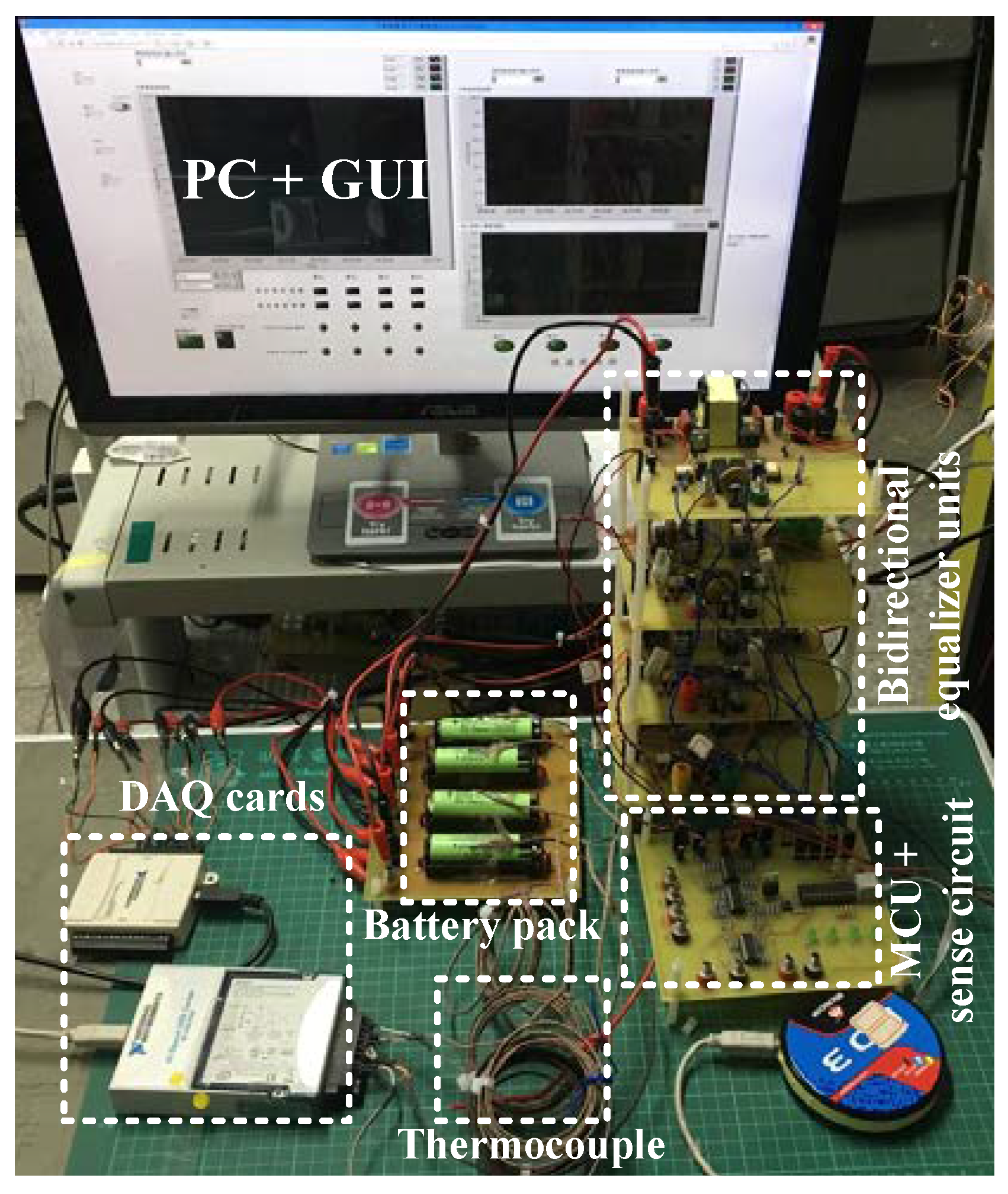
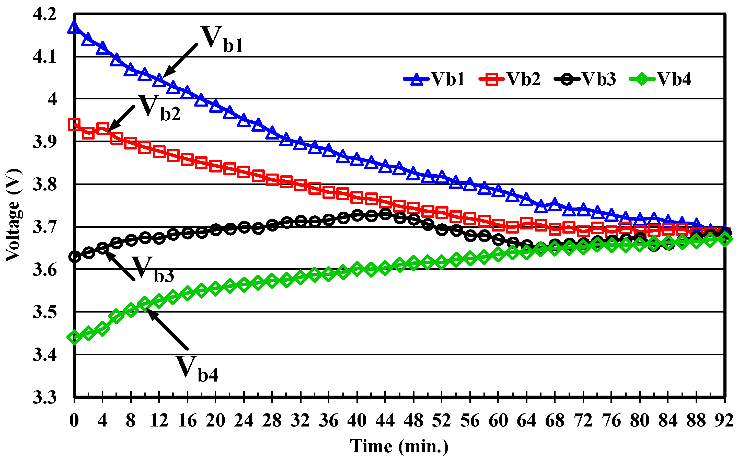
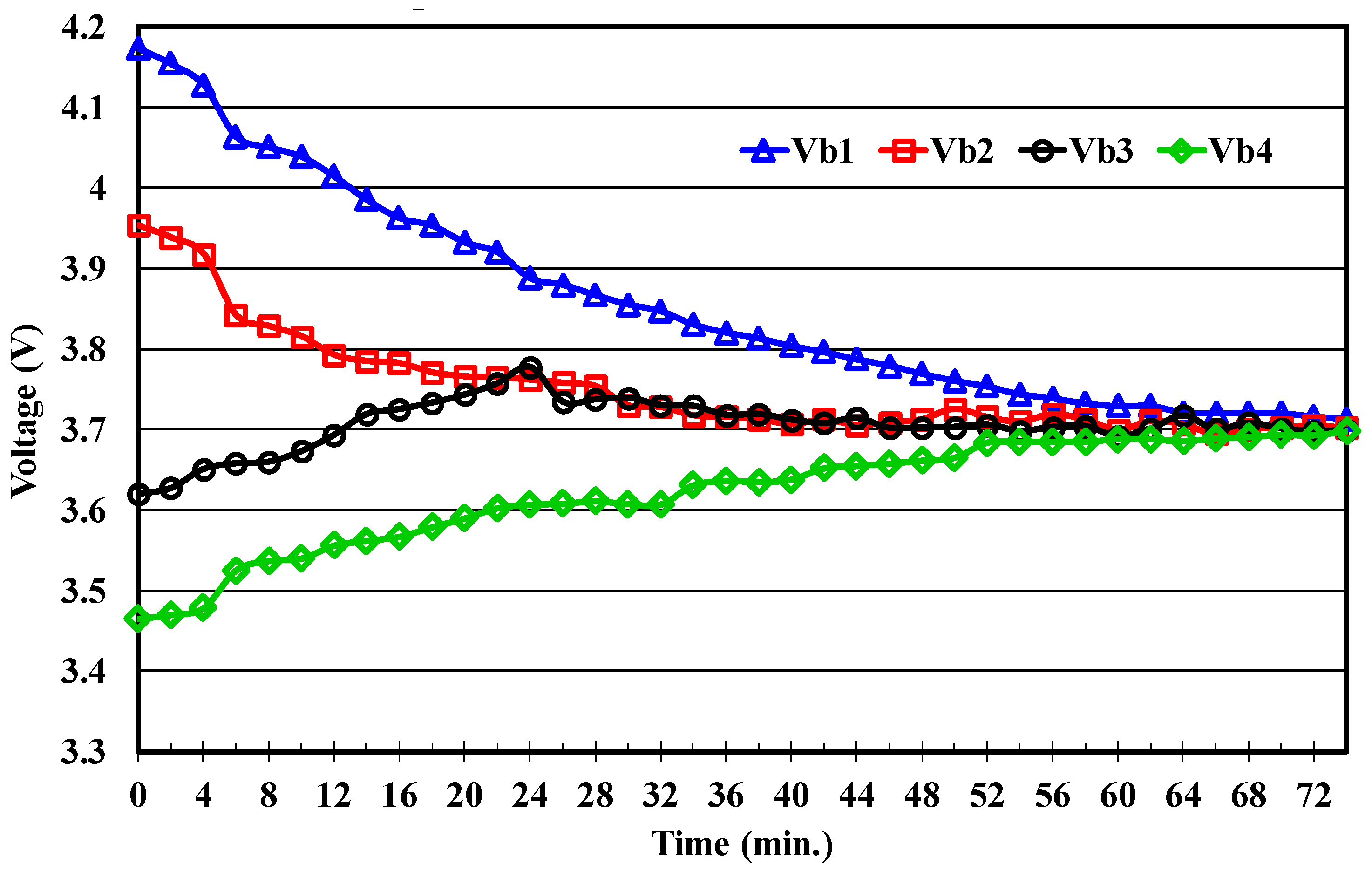
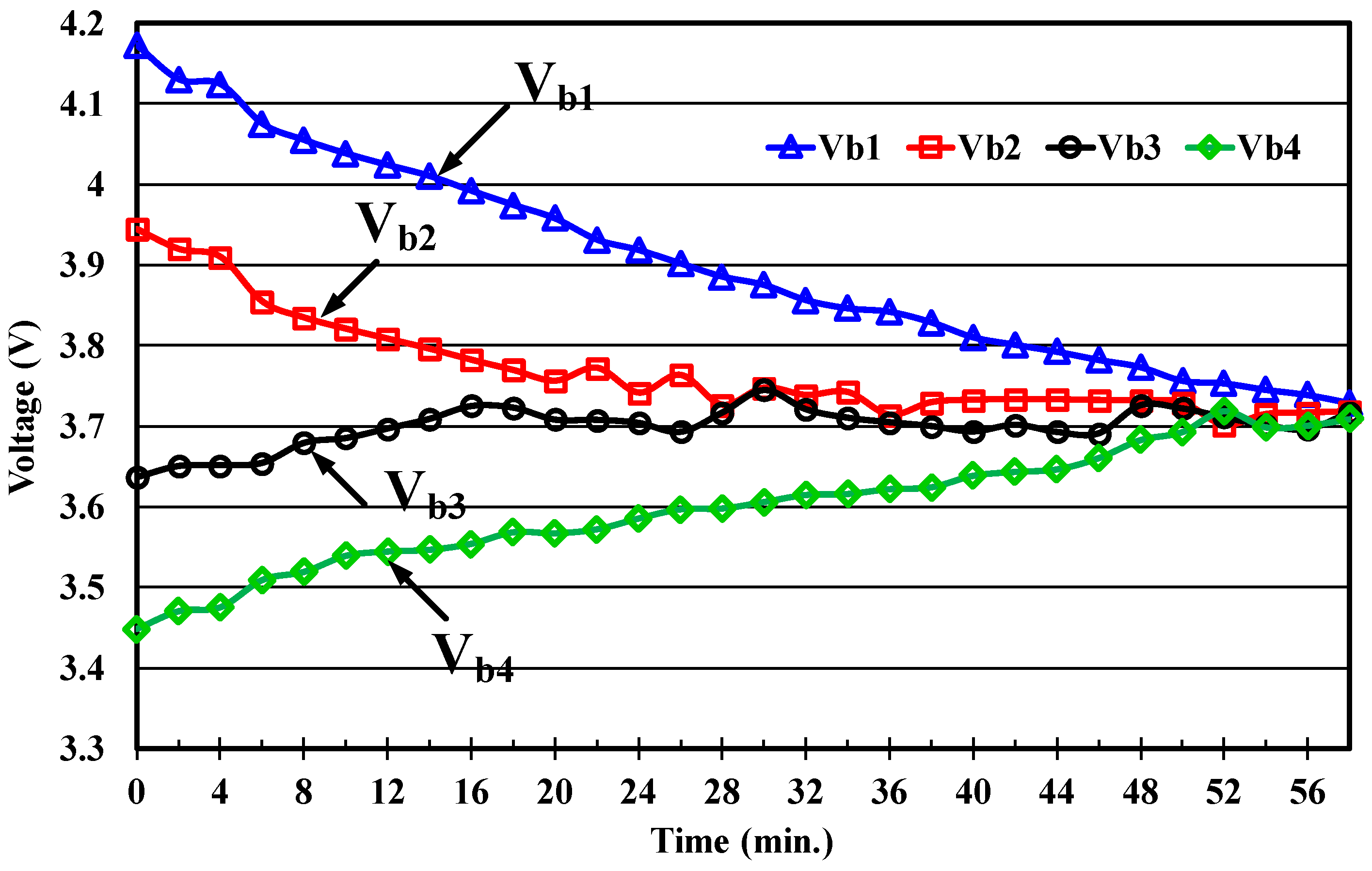
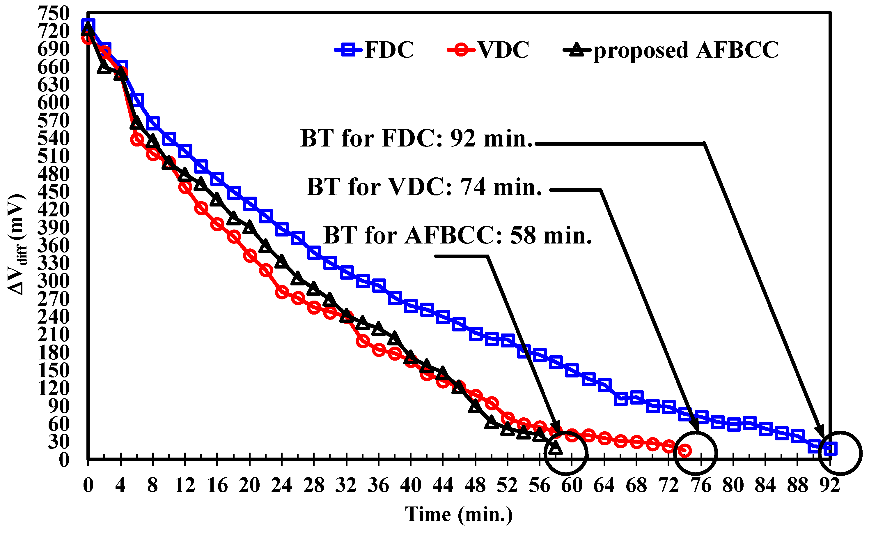
4. Experimental Results

The system specification, circuit design, and test results will be provided and analyzed in this section to confirm the correctness and feasibility of the proposed AFBCC method. In addition, the measured data obtained from two other balancing controls—the FDC method and VDC method—will also be provided for comparison to highlight the effectiveness and performance enhancement of the presented method. The duty cycle of the FDC method remains fixed throughout the equalization process. In this study, the duty cycle value of FDC method is set as 0.56 in C2P mode and 0.45 in P2C mode. These values can be obtained from Equations (2) and (4) by letting VB = 3.6 V and VPACK = 14.4 V. On the other hand, the VDC method calculates the duty cycle value using Equations (2) and (4). In this study, the MCU measures the instant voltage value of each cell (VB) and the voltage of the whole pack (VPACK), and then calculates the duty cycle value using Equation (2) or Equation (4), according to the operating modes. Figure 11 shows the photograph of the equalizer prototype implemented for performance verification.
The battery used for experiments in this study is NCR18650B (Panasonic Corporation, Gate City, Osaka, Japan) from Panasonic Corporation. Its capacity is 3400 mAh and its operating voltage range is 3.0 to 4.2 V. The battery pack used for equalization is composed of four cells connected in series. A prototyping system is also constructed for performing experiments, where the specifications and parameters of the designed bidirectional flyback converter are listed in Table 2. In order to achieve a fair comparison, the prototyping system setup and the testing condition remain unchanged, and the only difference is the balancing control techniques implemented in the MCU. In this study, the initial voltages of the test case for four cells before balancing are VB1 = 4.17 V, VB2 = 3.94 V, VB3 = 3.63 V, and VB4 = 3.44 V.
The recorded cell voltages over the entire balancing process for all three compared methods—the FDC, VDC and FABCC methods—are shown in Figure 12, Figure 13 and Figure 14, respectively. In addition, Figure 15 shows the voltage difference between the maximum voltage, Vmax, and minimum voltage, Vmin, obtained from these three methods. As described above, the voltages of VB1 and VB2 are greater than, and VB3 and VB4 are less than, the average voltage, Vavg, before equalization. Therefore, cell one and cell two will transfer energy to the battery pack (C2P mode), which results in voltage decline. At the same time, the pack will deliver energy to cell three and cell four (P2C mode), which leads to voltage rise. In this study, the preset condition for balancing termination is that the voltage difference (ΔVdiff) between Vmax and Vmin is less than 20 mV. It can be seen from Figure 12, Figure 13 and Figure 14 that all the cell voltages finally converge to the same value, and these three methods can all achieve equalization. Observing Figure 15, the voltage differences, ΔVdiff, of all the three studied approaches reduce from beyond 700 mV (imbalanced condition) to below 20 mV (balanced condition). It should be noted that the FDC, VDC, and the proposed AFBCC methods require 92, 74, and 58 min of balancing time (BT) to satisfy the specified termination condition, respectively.
Experimental results obtained by these three balancing methods will then be analyzed and compared to highlight the performance improvement of the proposed method. The main compared performance indices include the balancing time and the balancing efficiency. The cell voltages and state of charges (SOCs) of these three compared methods, before and after equalization, are measured and listed in Table 3 and Table 4, respectively. From Table 3, the cell voltages are unequal before equalization and there exists a large voltage difference, but these voltages converge to nearly the same value after equalization. From Table 3, the final cell voltages obtained by the proposed method are all higher than those of the other two methods. It should be noted that the higher the cell voltage, the lower the SOC loss during the equalization process. This fact can also be observed from Table 4. In Table 4, the SOC value of each cell is determined by the SOC versus open circuit voltage (OCV) curve of the utilized Li-ion battery, and the OCV is measured by resting the battery after equalization for one hour. From Table 4, the average SOC acquired by the proposed method after equalization is higher than those obtained by the other two methods. In other words, the proposed method has the best balancing efficiency. In addition, although this experiment utilizes the sensed cell voltage to perform equalization, it can still successfully achieve cell balancing.
Table 5 summarizes these measured results. From Table 5, the proposed AFBCC has the best performance, in terms of both balancing speed and balancing efficiency. Comparing with the FDC and VDC methods, the proposed AFBCC method can improve the balancing speed by 38.9% and 21.6%, respectively. From Table 5, although the VDC can ameliorate the balancing speed by varying the duty cycle, its ability to maintain constant balancing current in all operating conditions is limited, due to the non-ideal characteristics of the hardware circuit and battery. On the other hand, the proposed method can regulate the duty cycle in real time to maintain the balancing current, so the balancing speed is faster compared with that of the VDC method. For balancing efficiency, the proposed method can enhance the balancing efficiency by 3.3% and 0.8% compared with the FDC and VDC methods, respectively.

5. Conclusions

A fast equalizer with adaptive balancing current control and bidirectional energy transfer has been developed in this paper. To deal with the problem of decreased balancing current in the later equalization stage, and take the battery nonlinearity and circuit non-ideality into account, an adaptive balancing current control based on a fuzzy logic inference is proposed. The proposed balancing method can modulate the duty ratio adaptively, based on the cell and pack voltages, to maintain the balancing current. Therefore, the balancing time and balancing efficiency can be improved. The effectiveness and performance enhancement of the proposed method have been verified experimentally by the measured results, which were carried out on the constructed prototyping system. According to the experimental results, the proposed method owns a balancing efficiency of 89.6% and 38.9%, as well as a 21.6% reduction in the balancing time, have been achieved compared to the fixed duty cycle and variable duty cycle methods. The proposed equalizer has the advantages of modularization, fast balancing speed, and control flexibility without accurate mathematical models.

Author Contributions

This research article has three authors. Shun-Chung Wang and Yi-Hua Liu conceived the research method and designed the control strategy. Chun-Yu Liu constructed the prototyping circuits and performed the experiments. Shun-Chung Wang and Yi-Hua Liu analyzed the resulting data and wrote the manuscript.

Acknowledgments

This research was supported by the Ministry of Science and Technology (MOST), Taiwan. Under the grant number MOST-107-3113-E-110-001.

Conflicts of Interest

The authors declare no conflicts of interest.

References

  1. Zanabria, C.; Tayyebi, A.; Pröstl Andrén, F.; Kathan, J.; Strasser, T. Engineering Support for Handling Controller Conflicts in Energy Storage Systems Applications. Energies 2017, 10, 1595. [Google Scholar] [CrossRef]
  2. Zhou, F.; Xiao, F.; Chang, C.; Shao, Y.; Song, C. Adaptive Model Predictive Control-Based Energy Management for Semi-Active Hybrid Energy Storage Systems on Electric Vehicles. Energies 2017, 10, 1063. [Google Scholar] [CrossRef]
  3. Hua, C.; Fang, Y.H. A charge equalizer with a combination of APWM and PFM control based on a modified half-bridge converter. IEEE Trans. Power Electron. 2016, 31, 2970–2979. [Google Scholar] [CrossRef]
  4. Guo, X.; Kang, L.; Huang, Z.; Yao, Y.; Yang, H. Research on a Novel Power Inductor-Based Bidirectional Lossless Equalization Circuit for Series-Connected Battery Packs. Energies 2015, 8, 5555–5576. [Google Scholar] [CrossRef]
  5. Baronti, F.; Bernardeschi, C.; Cassano, L.; Domenici, A.; Roncella, R.; Saletti, R. Design and safety verification of a distributed charge equalizer for modular Li-ion batteries. IEEE Trans. Ind. Inform. 2014, 10, 1003–1011. [Google Scholar] [CrossRef]
  6. Baronti, F.; Fantechi, G.; Roncella, R.; Saletti, R. High-efficiency digitally controlled charge equalizer for series-connected cells based on switching converter and super-capacitor. IEEE Trans. Ind. Inform. 2013, 9, 1139–1147. [Google Scholar] [CrossRef]
  7. Chatzakis, J.; Kalaitzakis, K.; Voulgaris, N.C.; Manias, S.N. Designing a new generalized battery management system. IEEE Trans. Ind. Electron. 2013, 50, 990–999. [Google Scholar] [CrossRef]
  8. Lim, C.-S.; Lee, K.-J.; Ku, N.-J.; Hyun, D.-S.; Kim, R.-Y. A modularized equalization method based on magnetizing energy for a series-connected lithium-ion battery string. IEEE Trans. Power Electron. 2014, 29, 1791–1799. [Google Scholar] [CrossRef]
  9. Liu, X.; Sun, Y.; He, Y.; Zheng, X.; Zeng, G.; Zhang, J. Battery Equalization by Flyback Transformers with Inductance, Capacitance and Diode Absorbing Circuits. Energies 2017, 10, 1482. [Google Scholar] [CrossRef]
  10. Wang, S.; Kang, L.; Guo, X.; Wang, Z.; Liu, M. A Novel Layered Bidirectional Equalizer Based on a Buck-Boost Converter for Series-Connected Battery Strings. Energies 2017, 10, 1011. [Google Scholar] [CrossRef]
  11. Wu, T.; Moo, C.; Hou, C. A Battery Power Bank with Series-Connected Buck–Boost-Type Battery Power Modules. Energies 2017, 10, 650. [Google Scholar] [CrossRef]
  12. Lin, J. Development of a New Battery Management System with an Independent Balance Module for Electrical Motorcycles. Energies 2017, 10, 1289. [Google Scholar] [CrossRef]
  13. Velho, R.; Beirão, M.; Calado, M.; Pombo, J.; Fermeiro, J.; Mariano, S. Management System for Large Li-Ion Battery Packs with a New Adaptive Multistage Charging Method. Energies 2017, 10, 605. [Google Scholar] [CrossRef]
  14. Lin, C.; Mu, H.; Zhao, L.; Cao, W. A New Data-Stream-Mining-Based Battery Equalization Method. Energies 2015, 8, 6543–6565. [Google Scholar] [CrossRef]
  15. Zhang, D.; Zhu, G.; He, S.; Qiu, S.; Ma, Y.; Wu, Q.; Chen, W. Balancing Control Strategy for Li-Ion Batteries String Based on Dynamic Balanced Point. Energies 2015, 8, 1830–1847. [Google Scholar] [CrossRef]
  16. Li, W.; Kang, L.; Guo, X.; Yao, Y. Multi-Objective Predictive Balancing Control of Battery Packs Based on Predictive Current. Energies 2016, 9, 298. [Google Scholar] [CrossRef]
  17. Gallardo-Lozano, J.; Romero-Cadaval, E.; Milanes-Montero, M.I.; Guerrero-Martinez, M.A. Review: Battery equalization active methods. J. Power Sources 2014, 246, 934–949. [Google Scholar] [CrossRef]
  18. Baronti, F.; Roncella, R.; Saletti, R. Performance comparison of active balancing techniques for lithium-ion batteries. J. Power Sources 2014, 267, 603–609. [Google Scholar] [CrossRef]
  19. Manenti, A.; Abba, A.; Merati, A.; Savaresi, S.; Geraci, A. A new BMS architecture based on cell redundancy. IEEE Trans. Ind. Electron. 2011, 58, 4314–4322. [Google Scholar] [CrossRef]
  20. Kim, M.Y.; Kim, J.H.; Moon, G.W. Center-cell concentration structure of a cell-to-cell balancing circuit with a reduced number of switches. IEEE Trans. Power Electron. 2014, 29, 5285–5297. [Google Scholar] [CrossRef]
  21. Lu, R.; Zhu, C.; Tian, L.; Wang, Q. Super-capacitor stacks management system with dynamic equalization techniques. IEEE Trans. Magn. 2007, 43, 254–258. [Google Scholar] [CrossRef]
  22. Ouyang, Q.; Chen, J.; Zheng, J.; Fang, H. Optimal Cell-to-Cell Balancing Topology Design for Serially Connected Lithium-Ion Battery Packs. IEEE Trans. Sustain. Energy 2017, 3029, 350–360. [Google Scholar] [CrossRef]
  23. Imtiaz, A.M.; Khan, F.H. Time shared flyback converter based regenerative cell balancing technique for series connected Li-ion battery strings. IEEE Trans. Power Electron. 2013, 28, 5960–5975. [Google Scholar] [CrossRef]
  24. Moo, C.; Hsieh, Y.; Tsai, I. Charge equalization for series-connected batteries. IEEE Trans. Aerosp. Electron. Syst. 2003, 39, 704–710. [Google Scholar] [CrossRef]
  25. Young, C.M.; Chu, N.Y.; Chen, L.R.; Hsiao, Y.C.; Li, C.Z. A single-phase multilevel inverter with battery balancing. IEEE Trans. Ind. Electron. 2013, 60, 1972–1978. [Google Scholar] [CrossRef]
  26. Kim, C.H.; Kim, M.Y.; Park, H.S.; Moon, G.W. A modularized two-stage charge equalizer with cell selection switches for series-connected Lithium-ion battery string in an HEV. IEEE Trans. Power Electron. 2012, 27, 3764–3774. [Google Scholar] [CrossRef]
  27. Zhang, C.; Shang, Y.; Li, Z.; Cui, N. An Interleaved Equalization Architecture with Self-Learning Fuzzy Logic Control for Series-Connected Battery Strings. IEEE Trans. Veh. Technol. 2017, 66, 10923–10934. [Google Scholar] [CrossRef]
  28. Yun, J.; Yeo, T.; Park, J. High efficiency active cell balancing circuit with soft-switching technique for series-connected battery string. In Proceedings of the IEEE Applied Power Electronics Conference and Exposition (APEC), Long Beach, CA, USA, 17–21 March 2013; pp. 3301–3304. [Google Scholar]
  29. Li, S.; Mi, C.; Zhang, M. A high-efficiency active battery-balancing circuit using multi-winding transformer. IEEE Trans. Ind. Appl. 2013, 49, 198–207. [Google Scholar] [CrossRef]
  30. Kim, C.H.; Kim, M.Y.; Moon, G.W. A modularized charge equalizer using a battery monitoring IC for series-connected Li-ion battery strings in electric vehicles. IEEE Trans. Power Electron. 2013, 28, 3779–3787. [Google Scholar] [CrossRef]
  31. Ye, Y.; Cheng, K. An Automatic Switched-Capacitor Cell Balancing Circuit for Series-Connected Battery Strings. Energies 2016, 9, 138. [Google Scholar] [CrossRef]
  32. Daowd, M.; Antoine, M.; Omar, N.; van den Bossche, P.; van Mierlo, J. Single Switched Capacitor Battery Balancing System Enhancements. Energies 2013, 6, 2149–2174. [Google Scholar] [CrossRef]
  33. Shang, Y.; Zhang, Q.; Cui, N.; Zhang, C. A Cell-to-Cell Equalizer Based on Three-Resonant-State Switched-Capacitor Converters for Series-Connected Battery Strings. Energies 2017, 10, 206. [Google Scholar] [CrossRef]
  34. Zhang, Z.; Gui, H.; Gu, D.J.; Yang, Y.; Ren, X. A hierarchical active balancing architecture for lithium-ion batteries. IEEE Trans. Power Electron. 2017, 32, 2757–2768. [Google Scholar] [CrossRef]
  35. Narayanaswamy, S.; Kauer, M.; Steinhorst, S.; Lukasiewycz, M.; Chakraborty, S. Modular Active Charge Balancing for Scalable Battery Packs. IEEE Trans. Very Large Scale Integr. Syst. 2017, 25, 974–987. [Google Scholar] [CrossRef]
Figure 1. The utilized bidirectional flyback converter.
Energies 11 01052 g001
Figure 2. Cell-to-pack (C2P) mode: (a) subinterval one; (b) subinterval two.
Energies 11 01052 g002
Figure 3. Pack-to-cell (P2C) mode: (a) subinterval one; (b) subinterval two.
Energies 11 01052 g003
Figure 4. Four cells string case, (a) equalization mechanism; (b) wiring scheme.
Energies 11 01052 g004
Figure 5. Scheme of the adaptive fuzzy-logic-based balancing current control (AFBCC).
Energies 11 01052 g005
Figure 6. Membership functions (MFs) of (a) cell voltage VB; (b) pack voltage VPACK.
Energies 11 01052 g006
Figure 7. MFs of (a) C2P duty cycle; (b) P2C duty cycle.
Energies 11 01052 g007
Figure 8. Plots of the correlation among the input and output variables, (a) C2P mode; (b) P2C mode.
Energies 11 01052 g008
Figure 9. The system configuration of the proposed balancer.
Energies 11 01052 g009
Figure 10. The flowchart of the proposed AFBCC.
Energies 11 01052 g010
Figure 11. Photograph of the implemented equalizer prototype.
Energies 11 01052 g011
Figure 12. Voltage balance curve obtained by the fixed duty cycle (FDC) method.
Energies 11 01052 g012
Figure 13. Voltage balance curve obtained by the variable duty cycle value (VDC) method.
Energies 11 01052 g013
Figure 14. Voltage balance curve obtained by the proposed AFBCC method.
Energies 11 01052 g014
Figure 15. Curves of the voltage difference (ΔVdiff) variations obtained by the three methods.
Energies 11 01052 g015
Table 1. Rule Base of the proposed adaptive fuzzy-logic-based balancing current control (AFBCC).
VPACK
VB
LMLMMHH
HL
Rule1
L
Rule2
ML
Rule3
ML
Rule4
M
Rule5
MHL
Rule6
ML
Rule7
ML
Rule8
M
Rule9
M
Rule10
MML
Rule11
ML
Rule12
M
Rule13
M
Rule14
MH
Rule15
MLML
Rule16
M
Rule17
M
Rule18
MH
Rule19
MH
Rule20
LM
Rule21
M
Rule22
MH
Rule23
MH
Rule24
H
Rule25
Table 2. Specification and experimental parameter setting.
ItemSpec.ItemSpec.
Turns ration (N1:N2)8:32Dead time0.83 (μs)
Switching frequency30 (kHz)Magnetization inductance15 (μH)
Duty cycle range of C2P mode52%~62%Leakage inductance1 (μH)
Duty cycle range of P2C mode43%~47%
Table 3. Cell voltages before and after equalization.
VcellBefore EqualizationAfter Equalization
Method VB1VB2VB3VB4VB1VB2VB3VB4
FDC4.17 V3.94 V3.63 V3.44 V3.68 V3.68 V3.68 V3.67 V
VDC4.17 V3.95 V3.62 V3.46 V3.71 V3.70 V3.69 V3.69 V
AFBCC4.17 V3.94 V3.63 V3.44 V3.72 V3.71 V3.71 V3.70 V
Table 4. State of charges (SOCs) before and after equalization.
SOCBefore EqualizationAfter Equalization
Method SOC1SOC2SOC3SOC4SOC1SOC2SOC3SOC4
FDC100%81%48%20%54%54%54%53%
VDC100%82%46%22%56%55%55%55%
AFBCC100%81%48%20%56%56%56%55%
Table 5. Comparisons of the three equalization methods.
MethodBefore EqualizationAfter EqualizationResults
ΔVdiffTotal SOCΔVdiffTotal SOCTime (min)Balancing Efficiency (%)
FDC730 mV249%20 mV215%9286.3%
VDC708 mV250%20 mV222%7488.8%
AFBCC724 mV249%20 mV223%5889.6%

