Article

Open- and Short-Circuit Fault Identification for a Boost dc/dc Converter in PV MPPT Systems

by
Diego R. Espinoza Trejo
1,*,
Ernesto Bárcenas
1,
José E. Hernández Díez
1,
Guillermo Bossio
2 and
Gerardo Espinosa Pérez
3
1
Coord. Acad. Región Altiplano, Universidad Autónoma de San Luis Potosí, 78700 Matehuala, S.L.P., Mexico
2
Applied Electronics Group, Universidad Nacional de Río Cuarto, Río Cuarto 5800, Córdoba, Argentina
3
Faculty of Engineering, Universidad Nacional Autónoma de México, México City 04510, Mexico
*
Author to whom correspondence should be addressed.
Energies 2018, 11(3), 616; https://doi.org/10.3390/en11030616
Submission received: 8 February 2018 / Revised: 26 February 2018 / Accepted: 6 March 2018 / Published: 9 March 2018
(This article belongs to the Section F: Electrical Engineering)

Abstract

:
This paper proposes a fault identification system for short and open-circuit switch faults (SOCSF) for a dc/dc converter acting as a Maximum Power Point Tracker (MPPT) in Photovoltaic (PV) systems. A closed-loop operation is assumed for the boost dc/dc converter. A linearizing control plus a Proportional-Derivative (PD) controller is suggested for PV voltage regulation at the maximum power point (MPP). In this study, the SOCSF are modeled by using an additive fault representation and the fault identification (FI) system is synthesized departing from a Luenberger observer. Hence, an FI signal is obtained, which is insensitive to irradiance and load current changes, but affected by the SOCSF. For FI purposes, only the sensors used in the control system are needed. Finally, an experimental evaluation is presented by using a solar array simulator dc power supply and a boost dc/dc converter of 175 W in order to validate the ideas this study exposes.

1. Introduction

In spite of spectacular progress of the Photovoltaic (PV) solar energy in the last years, some problems remain to be solved in order to maximize the efficiency and security (on-site diagnostic functions) of PV systems. In this regard, reliability and high conversion efficiency of power electronic converters (PEC) must be taken into account for PV systems design. On the one hand, PV maximum power point tracking (MPPT) systems, based on dc/dc power converters, are responsible for high tracking efficiency. Indeed, MPPT systems are operated through a closed-loop structure such that an improved tracking efficiency is obtained in comparison with open-loop structures, [1,2,3,4,5,6]. On the other hand, switching devices are the most fragile components in PEC [7], which are mainly affected by thermal stress conditions [8]. Recently, the negative effects of conventional MPPT algorithms on the thermal stresses and reliability of PEC were presented in [9]. Therefore, a fault identification (FI) system for short- and open-circuit switch faults (SOCSF) in MPPT systems would be useful to increase the efficiency and reliability of PV systems.
With this goal in mind, some fault detection and isolation (FDI) proposals have been reported so far in the literature. In [10], an FDI technique is proposed for dc/dc converters by using the magnetic component voltage and the switch gate-driver signals. SOCSF were detected and isolated through this proposal. The magnetic component voltage is obtained by means of an auxiliary winding in the inductor element. Meanwhile, switch gate-driver signals are obtained from the control circuit. In [11], an FDI algorithm for SOCSF was presented for single-switch dc/dc power converters by considering any duty cycle and switching frequency operation. In this case, the switch gate driver signals are also used in the FDI stage in conjunction with the sign of the inductor current slope. In addition, a fault-tolerant topology was presented, where a redundant switch and a bidirectional switch are required for power converter reconfiguration ( Figure 1). More recently, an FDI system was proposed in [12] for SOCSF by using a new Rogowski coil sensor (RCS). Once more, the switch gate-driver signals are used but now in conjunction with the RCS output. An important characteristic of these FDI techniques [10,11,12] is that the fault detection time is less than one switching period. Nevertheless, the robustness of these FDI techniques against disturbances has not been detailed. Moreover, proposals such as [10,12] could be considered as invasive FDI methods. A few works have studied SOCSF diagnosis dedicated to PV systems. First, open-circuit switch FDI and fault-tolerant strategy in a three-level boost converter were proposed in [13] for a PV power system supplying batteries. In that paper, the PV power, voltage and current are required for fault detection. Meanwhile, the unbalance between the input capacitor voltages is used for fault isolation. In [14], an open-circuit switch FDI system was carried out for interleaved dc/dc converters. In that study, once more, the switch gate driver signals are used, but now the dc-link input current and the duty cycle are also required for FDI purposes. More recently, a fast Field Programmable Gate Array (FPGA) based FDI system and fault-tolerant boost converter for SOCSF was presented in [15]. Again, the switch gate-driver signals and the inductor current were used for FDI purposes. It is worth mentioning that in all these FDI techniques [13,14,15], no detailed evaluation has been considered by including actual PV scenarios, such as sudden irradiance drops. Hence, the present paper highlights the robustness of observer-based FI techniques against varying irradiance conditions. It is worth noting that, these kind of FI techniques have widely been reported in the literature, [16]. Indeed, in a recent work [17], an observer-based FI system was proposed for switching power converters described by switched linear systems. Arbitrary faults in components (passive or switching elements) and sensors were considered in that proposal. Faults in the switching devices are modeled through an additive structure. In this case, an open-loop observer (without correction terms) is employed for residual generation. Nevertheless, short-circuit switch fault conditions have not been described in the experimental results stage. Now, in the present paper, an observer-based FI system is proposed for PV MPPT systems. SOCSF can be identified through this proposal. It should be noted that, FI follows FDI as the size and time-variant behavior of the fault are determined by the FI system, [18]. The averaged nonlinear model of the boost dc/dc power converter is employed for the FI algorithm synthesis. The results are specifically illustrated for the boost converter. Nonetheless, the main idea can easily be extrapolated to another topologies. The main contributions of this work are:
  • An FI system operating under the influence of a closed-loop control system. In fact, the fault modeling is carried out by considering the nominal control algorithm.
  • An FI system which requires only the information demanded by the control system, i.e., no extra sensors are needed in the FI stage.
  • An FI system decoupled from the PV and load currents. Consequently, robust against varying irradiance conditions and disturbances in the load element.
  • An experimental evaluation carried out by taking into account varying irradiance conditions.
Finally, the remaining part of the paper is organized as follows. The nominal MPPT controller is presented in Section 2. Next, the averaged nonlinear faulty model of the boost dc/dc power converter is presented in Section 3. The FI system proposed in this work is presented in Section 4. Finally, the experimental results are illustrated in Section 5 and the conclusions are given in Section 6.

2. Nominal MPPT Controller

This study considers a boost dc/dc power converter as illustrated in Figure 1. An averaged model of this system is obtained departing from the electrical circuit, which is represented by the following nonlinear system:
x ˙ = A x + g ( x ) u o + D i p v + E i o , y = C x ,
where y = [ y 1 , y 2 , y 3 ] T , D = [ C p v - 1 , 0 , 0 ] T , E = - [ 0 , 0 , C - 1 ] T ,
A = 0 - C p v - 1 0 L - 1 0 - L - 1 0 C - 1 0 ; C = 1 0 0 0 1 0 0 0 1 ; g ( x ) = 0 L - 1 x 3 - C - 1 x 2 ,
And x = x 1 , x 2 , x 3 T = v p v , i L , v o T . Here, the input voltage in the terminals of the capacitor C p v is represented by v p v , the current of inductor L by i L and the voltage in the terminals of the output capacitor C by v o . In addition, the PV current is denoted by i p v , which is described as i p v ( t ) = χ ( x 1 , G , T , t ) , where G denotes the irradiance and T the PVM’s temperature, [19]. Moreover, the load current i o is considered as an unknown and arbitrary signal. Lastly, u o is the control action (duty cycle for the switch Q). As a consequence, it has a limited operating range, u o [ 0 , 1 ] .
The nominal MPPT controller synthesis is carried out by departing from the input-output linearization control technique [20] and by taking advantage of the model given in Equation (1). This controller design perspective was recently used in [1] for a buck dc/dc converter. Now, an extension for the boost converter is considered in this study. For this, define the error variable x ˜ 1 = x 1 - x 1 , where the voltage reference value ( x 1 ) is obtained departing from a MPP searching technique (MPP-ST). Thus, the main purpose of this section is to propose a control law for the duty cycle u o such that:
lim t x ˜ 1 ( t ) = 0 ,
guaranteeing internal stability and a desired performance. Therefore, the MPPT controller suggested in this work is given by:
u o = γ - x 3 - 1 υ , γ = x 3 - x 1 x 3 - 1 , υ = k p ( y 1 - y 1 ) + k d C p v - 1 x 2 - i p v , k p = 16 ( N c ξ c ) - 2 L C p v f s w 2 , k d = 8 N c - 1 L C p v f s w ,
where ξ c represents the damping factor, f s w is the switching frequency and the settling time is chosen as t s = N c × T s w , with T s w = 1 / f s w [2,6]. In addition, the voltage reference y 1 = x 1 required in Equation (2) can be obtained by different MPP-ST [21,22,23,24]. In the present work, the Fractional Method is used due to its simplicity [24]. Nevertheless, the control algorithm given in Equation (2) (detailed in Appendix A) is independent from the method used as MPP-ST.

3. Fault Modeling

In Figure 1, a short-circuit switch fault (SCSF) is represented by the normally open switch S s c . While, the open-circuit switch fault (OCSF) is symbolized by the normally closed switch S o c . In this study, an additive actuator fault representation is considered for SOCSF [18], i.e., the control action is modeled as:
u = u o + δ f ,
where u o is the nominal control and δ f is the additive fault effect, which is also consistent with the previous result given in [17]. In the following, a steady-state analysis is carried out for SOCSF. For this, the steady-state values involved in this analysis are defined in upper case letters. Therefore, the actuator fault representation at steady-state is represented as:
U = U o + Δ f ,
where:
  • U o : Linearizing control law (Nominal duty cycle for the switch Q at steady-state).
  • Δ f : Actuator switch fault of the switch Q at steady-state.
Remark 1.
It is worth noting that the auxiliary control law ( υ ) in Equation (2), in a free-fault scenario, converges to zero as the PV voltage converges to y 1 and the inductor current at steady-state is equal to the PV current. As a consequence, the nominal control action at steady state is given by:
U o = Γ = 1 - X 1 X 3 ,
where
Γ = lim t γ ; Y 1 = X 1 = lim t x 1 ; and X 3 = lim t x 3 .

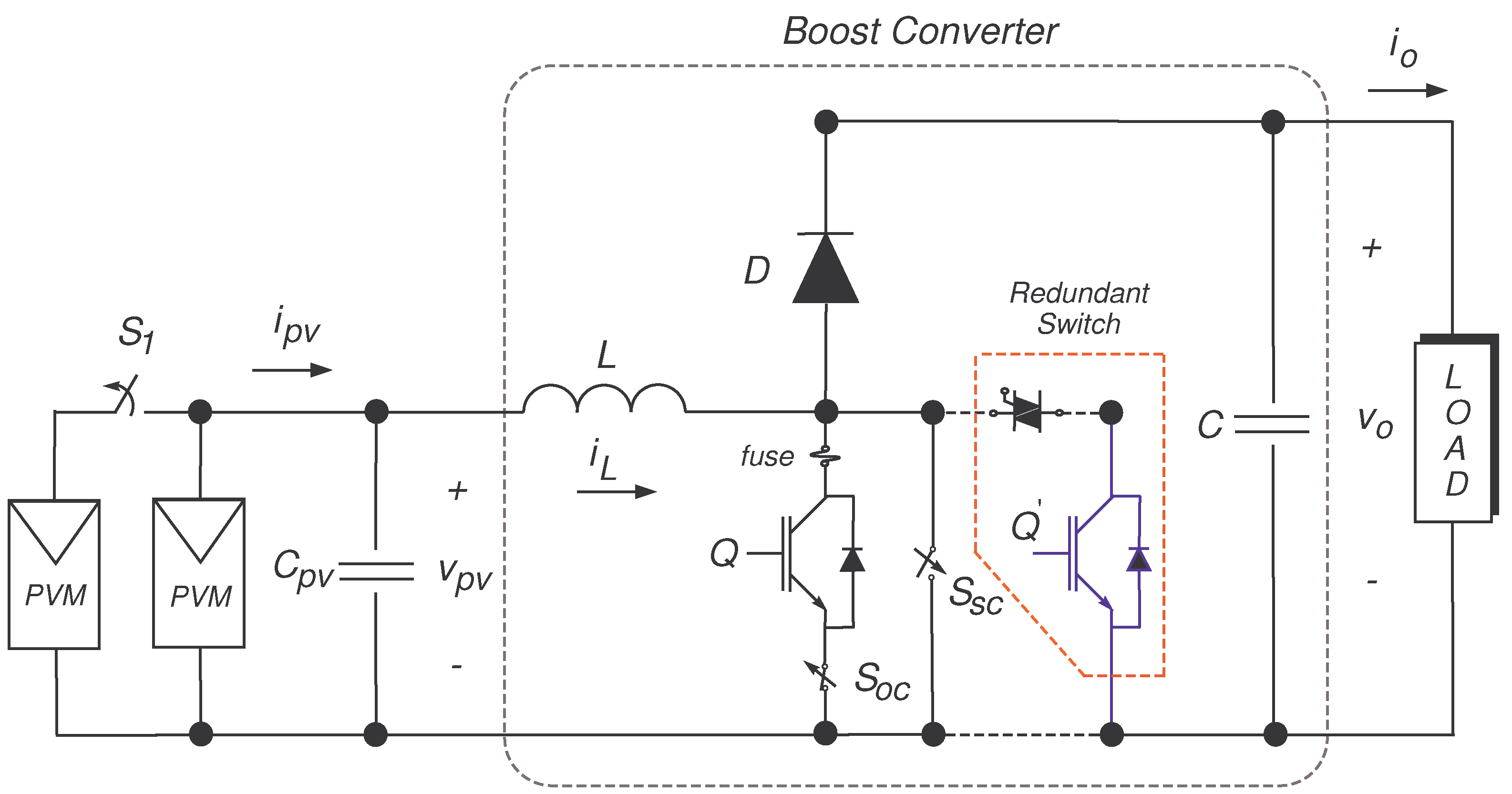
3.1. Open-Circuit Switch Fault Modeling

Under an OCSF condition the switches S o c and S s c are open. As a consequence, after the open-circuit switch fault is triggered at t = t f , the PV voltage at steady-state is equal to the open-circuit PV voltage ( V o c ) , i.e., Y 1 = V o c . In addition, the inductor current at steady state is equal to the PV current, i.e., X 2 = I p v . Hence, by taking into account the control algorithm suggested in Section 2 under an open-circuit fault scenario, the control action U at steady-state is defined by:
U = U o + ( k p - 1 ) Y 1 - Y 1 X 3 .
As such, departing from Equation (4) the open-circuit fault profile is identified as:
Δ f ( t ) ( k p - 1 ) V o c - Y 1 X 3 R + ; t t f and k p > 1 .
where Y 1 is the voltage reference.

3.2. Short-Circuit Switch Fault Modeling

Now, in an SCSF condition the switches S o c and S s c are closed. In this case, after the short-circuit fault is triggered at t = t f , the PV voltage decreases to zero, i.e., Y 1 = 0 . Once more, the inductor current at steady state satisfies that X 2 = I p v . Thus, by taking into account the control algorithm suggested in Section 2 under a short-circuit fault scenario, the control action U at steady-state is defined by:
U = U o - ( k p - 1 ) Y 1 - Y 1 X 3 .
Therefore, the short-circuit fault profile is identified as:
Δ f ( t ) - ( k p - 1 ) Y 1 X 3 R - ; t t f and k p > 1 .
Result 1.
Firstly, if the output voltage x 3 , the open-circuit voltage v o c and the voltage reference y 1 are piecewise constant time functions, then departing from Equations (7) and (9), SOCSF can be characterized by piecewise constant fault profiles. Secondly, note that SOCSF could be isolated by taking into account the sign of these fault profiles, i.e., for OCSF the fault profile Δ f will be positive and negative for SCSF.
Based on the nominal model Equation (1) and the additive fault representation Equation (3), SOCSF can be represented through the following nonlinear system:
x ˙ = A x + g ( x ) u - δ f + D i p v + E i o , y = C x .
Remark 2.
Note that Equation (10) is sensitive to the fault δ f . However, it is also sensitive to PV and load currents changes, i p v and i o respectively, which are considered in this study as disturbances and arbitrary signals. Therefore, a subsystem affected by the fault δ f but decoupled from the PV and load currents is needed to avoid false alarms in the FI system.

4. Observer-Based Fault Identification System

The FI system this work proposes is detailed in this section. This is derived in two stages. First, a decoupled subsystem from the load current i o but sensitive to the fault δ f is obtained by using two linear mappings. Then, a residual generator is constructed by designing a Luenberger observer for this subsystem. The two linear mappings, one in the state space Φ and one in the output space Ψ are given by:
z = z 1 z 2 = z 11 z 12 z 2 = Φ x = 1 0 0 0 1 0 0 0 1 x 1 x 2 x 3 ,
and
w = w 1 w 2 = w 11 w 12 w 2 = Ψ y = 1 0 0 0 0 1 0 1 0 y 1 y 2 y 3 .
It is worth noting that Φ and Ψ only establish a suitable partition in two subsystems. In this way, through these linear mappings the subsystem ( z 1 , w 1 ) given in Equation (11) is sensitive to the fault δ f but insensitive to the load current i o and represented in compact form as:
z ˙ 1 = F z 1 + h i p v , w 12 , u - p w 12 δ f , w 11 = M z 1 ,
where p w 12 = 0 , L - 1 w 12 T ,
h i p v , w 12 , u = C p v - 1 i p v L - 1 w 12 u - 1 ;
F = 0 - C p v - 1 L - 1 0 ; M = 1 0 .
Proposition 1.
Consider the subsystem Equation (11). Assume that:
A.1 
The pair ( M , F ) is observable.
A.2 
The PV current ( i p v ) , the input voltage x 1 ( w 11 in the new coordinates) and the output voltage x 3 ( w 12 in the new coordinates) are available for measurement.
A.3 
The duty cycle u is a signal available from the control algorithm.
A.4 
The parameters L, C and C p v are known and constants.
A.5 
The output voltage x 3 is a piecewise constant signal.
Then, a residual signal ( r ) is constructed departing from a Luenberger observer for subsystem Equation (11) given by:
z ^ ˙ 1 = F z ^ 1 + h i p v , w 12 , u + K w 11 - w ^ 11 , w ^ 11 = M z ^ 1 ,
where z ^ 1 and w ^ 11 are the estimate of z 1 and w 11 , respectively. Hence, the residual signal ( r ) defined as:
r = w 11 - w ^ 11 = M z 1 - z ^ 1 ,
is sensitive to the fault δ f , insensitive to the inputs ( i p v , i o ) and exponentially converges to the equilibrium point (the origin) in the absence of the fault δ f . A desired performance is achieved by choosing the observer gains K = [ k 1 , k 2 ] T as:
k 1 = 8 N o f s w , k 2 = 1 L - 16 C p v f s w 2 ( ξ o N o ) 2 ,
where the settling time is considered equal to N o times the T s w , i.e., t s o = N o × T s w and ξ o is a desired damping factor.
Proof of Proposition 1.
The proof of the above proposition can be followed by using the basic tools of dynamical system theory. Nevertheless, the observer gains selection is briefly detailed in Appendix B.  ☐
Remark 3.
From the observer dynamics Equation (12), it should be noted that for the observer implementation, the PV current ( i p v ) , the output voltage ( x 3 ) and the PV voltage ( x 1 ) have to be measurable. Nevertheless, this information is available from the nominal control algorithm given in Equation (2), i.e., no extra sensors are needed for FI purposes.

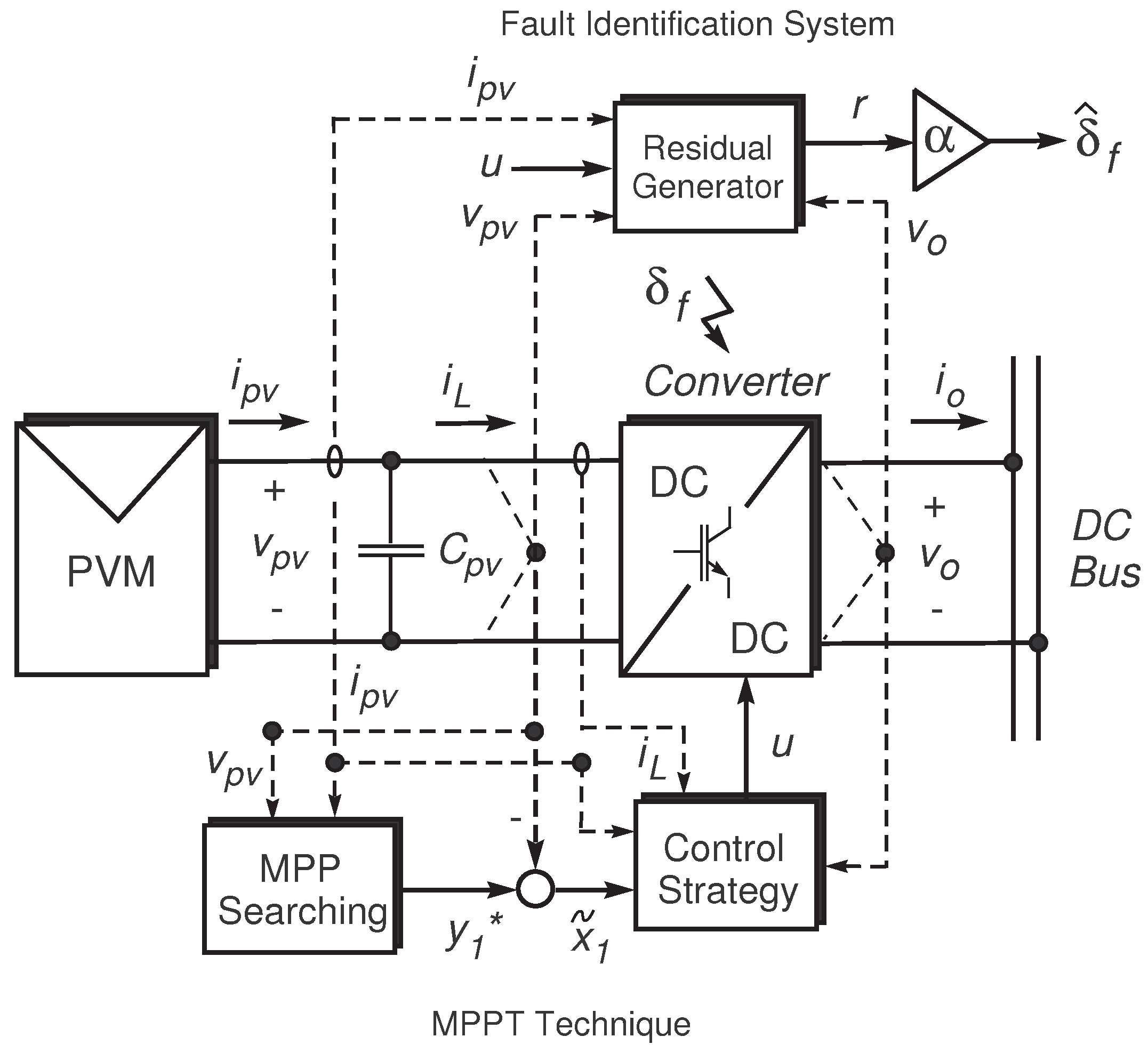
Fault Identification Stage

The FI system for SOCSF is developed in this section. For this, the error signals are defined as e 1 = z 11 - z ^ 11 , e 2 = z 12 - z ^ 12 and e = e 1 , e 2 T . Departing from this definition, the error dynamics can be written in a compact form as:
e ˙ = ( F - K M ) e - B f ˜ , r = M e ,
where B = 0 , L - 1 T and f ˜ = w 12 δ f . Note that, the error dynamics is defined by a linear and invariant time system. As a consequence, if assumption A.5. is satisfied and 0 < ξ o < 1 , then the input-output transfer function G ( s ) of the linear system Equation (13) is obtained:
G ( s ) = r ( s ) δ f ( s ) = X 3 L C p v 1 ( s + a ) 2 + w 2 ,
where
a = k 1 2 ; and w = a 1 - ξ o 2 ξ o .
As a result, the step response is given as:
r ( t ) = X 3 L C p v a 2 + w 2 1 - e - a t cos w t + a w sin w t δ f .
Therefore, the FI signal ( δ ^ f ) is achieved by scaling the residual signal ( r ) as:
δ ^ f ( t ) = α × r ( t ) ,
where the scaling factor ( α ) is given by:
α = L C p v a 2 + w 2 X 3 .
Consequently, the steady-state value of the fault identification is defined as:
Δ ^ f = lim t δ ^ f ( t ) .
In addition, the steady-state value for Δ ^ f under SOCSF can be verified departing from Equations (7) and (9). Finally, a block diagram of the FI system suggested in this paper is illustrated in Figure 2.
Remark 4.
From the error dynamics Equation (13), it is worth noting that the residual signal ( r ) is decoupled from the inputs ( i p v , i o ). As a consequence, the FI system proposed in this work is robust against irradiance and load current changes.

5. Experimental Validation

In this section, the FI system proposed in this paper is evaluated by considering a closed-loop operation and varying irradiance conditions under two fault scenarios, i.e, (E1) OCSF and (E2) SCSF.

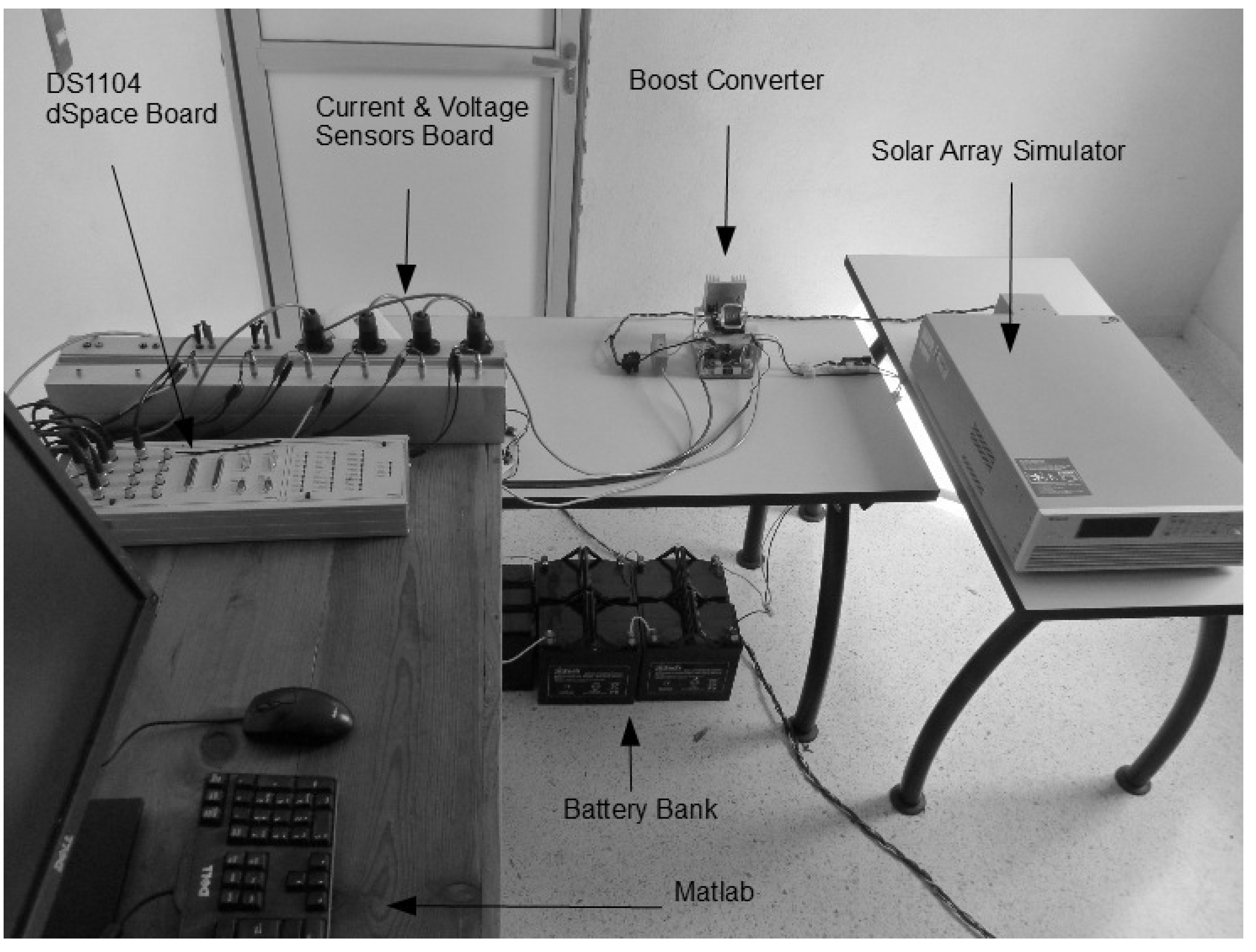
5.1. Testing Workbench

The proposed FI system is evaluated against a varying irradiance condition by using a ramp gradient of 80 W / m 2 / s with two different irradiance levels, from 100 to 500 W / m 2 (low to medium irradiance). The experimental results were carried out by using a solar array simulator dc power supply. The parameters defined in the solar array simulator are: voltage in MPP, v m p p = 35 V , and power in MPP, P m p p = 175 W . The boost dc/dc converter is operating at a switching frequency of 15 KHz and its parameters have been declared as C p v = 500 μ F , L = 4.77 m H and C = 144 μ F . A battery bank, composed by 5 lead-acid batteries of 80 Ah with a rated voltage of 12 V each, has been contemplated as load during the experiments. The nominal control and the diagnosis algorithm were implemented in a DS1104 dSpace board at a sampling frequency ( f s ) of 50 KHz . The control parameters were chosen as ξ c = 1 and N c = 8 while the observer parameters as ξ o = 1 2 and N o = 8 . The controller and observer gains are given in Table 1 and the experimental test bench is illustrated in Figure 3.

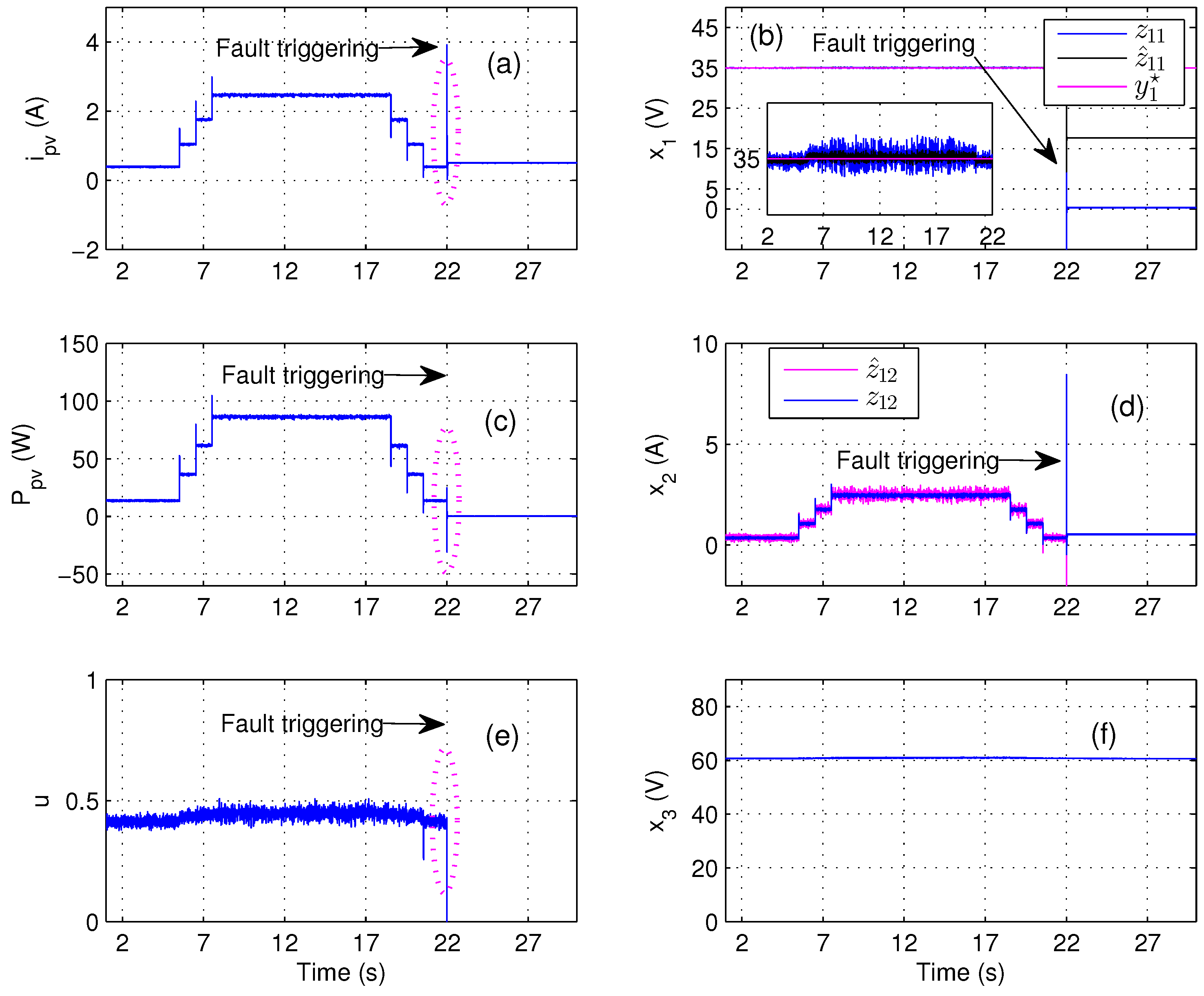
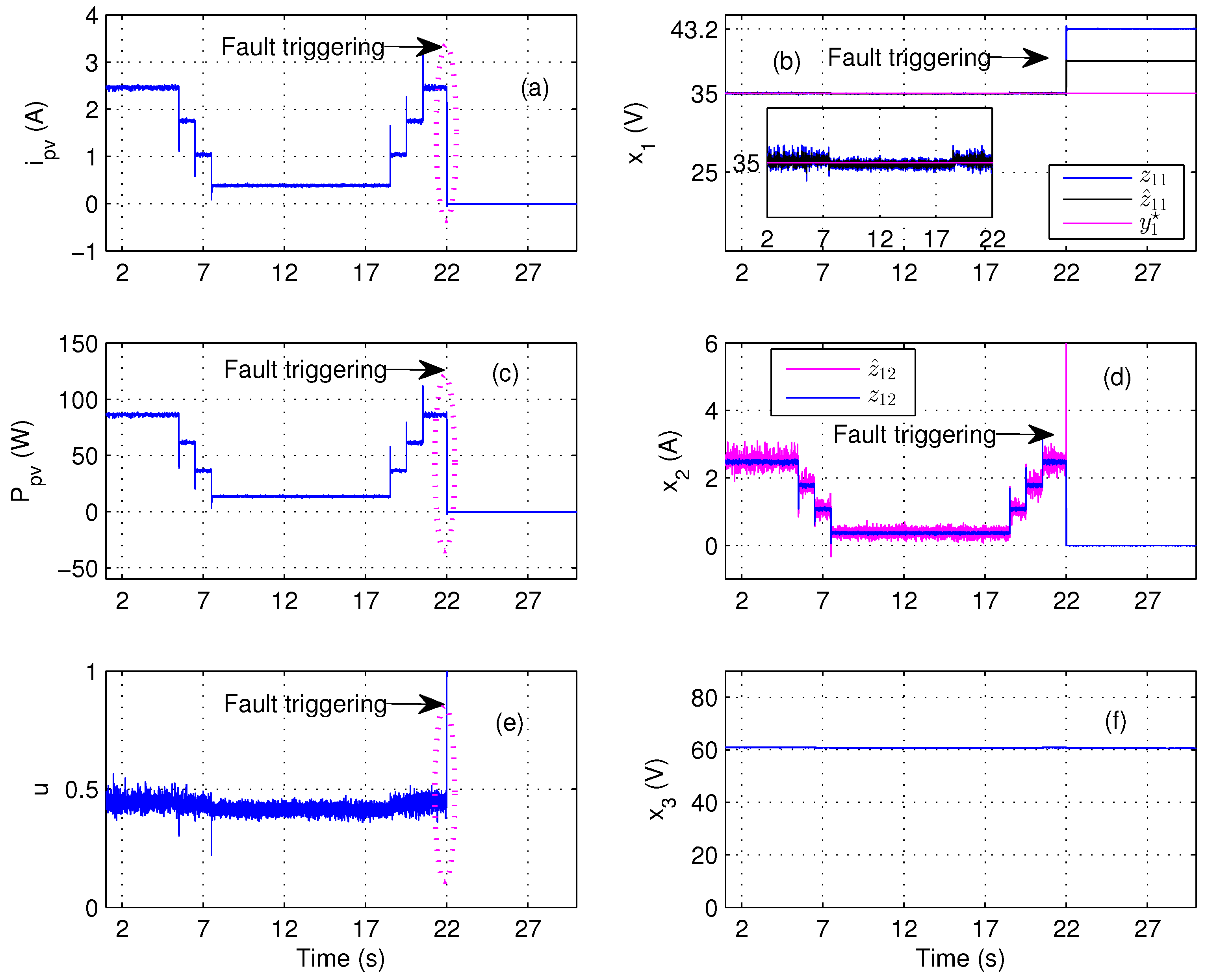
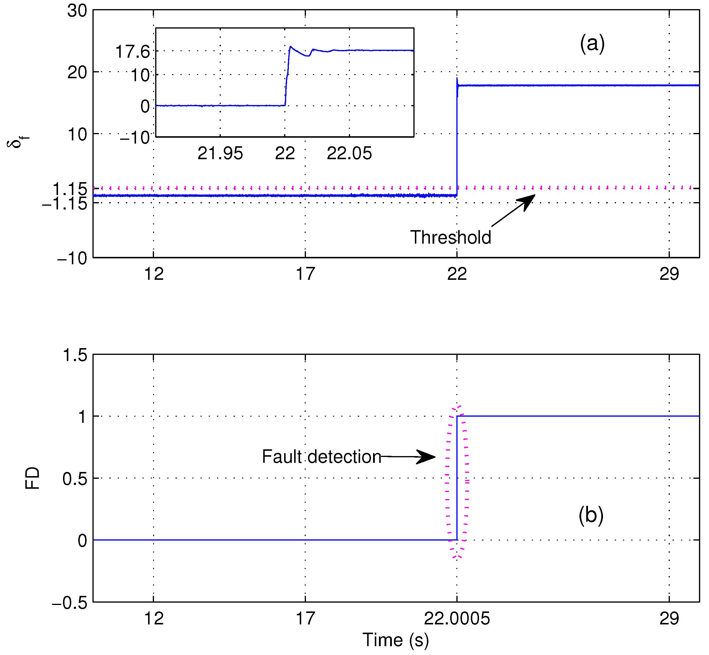
5.2. Experimental Test E1

The OCSF scenario is considered in this experiment. It is worth noting from Figure 4, that a varying irradiance condition is emulated by using a ramp gradient of 80 W / m 2 / s with two different irradiance levels, from 100 to 500 W / m 2 . This disturbance can be easily visualized through the PV current i p v (Figure 4a), the PV power P p v (Figure 4c) and the inductor current x 2 (Figure 4d). Nevertheless, in spite of this varying irradiance condition, the PV voltage x 1 (Figure 4b) is well regulated at the MPP (35 V ) through the control signal u (Figure 4e). According with the batteries array, the output voltage x 3 is kept around 60 V as visualized in Figure 4f. Additionally, the estimated states z ^ 11 and z ^ 12 are illustrated in Figure 4b,d, respectively. Note that, the states estimation is correct under a free-fault scenario. The OCSF is triggered at t = 22.0 s . Under this fault condition, the PV current i p v , the PV power P p v and the inductor current x 2 go down to zero (Figure 4). The control signal u tries to compensate the fault condition as can be observed in Figure 4e. However, the PV voltage x 1 increases up to the open-circuit voltage V o c = 43.22 V (null PV power) (Figure 4b). Meanwhile, the output voltage x 3 is kept around 60 V . The results of the FI stage are illustrated in Figure 5. Here, the FI signal δ ^ f can be observed in the Figure 5a. This signal at steady state increases up to Δ ^ f = 17.6 , as expected from the result given in (7). Note that the estimated fault profile ( δ ^ f ) is constant, which is consistent with Result 1. Also, the FI signal is never affected by the varying irradiance condition. It is worth noting that under this condition, the operation of the boost dc/dc converter presents a varying duty cycle. Therefore, the FI system is independent of the duty cycle value. In addition, as can be observed in Figure 5b, the threshold is selected as T h = 1.15 ( T h 6.6 % Δ f ) . Consequently, the fault detection time is approximately 500 μ s, which is equivalent to 8 switching periods.

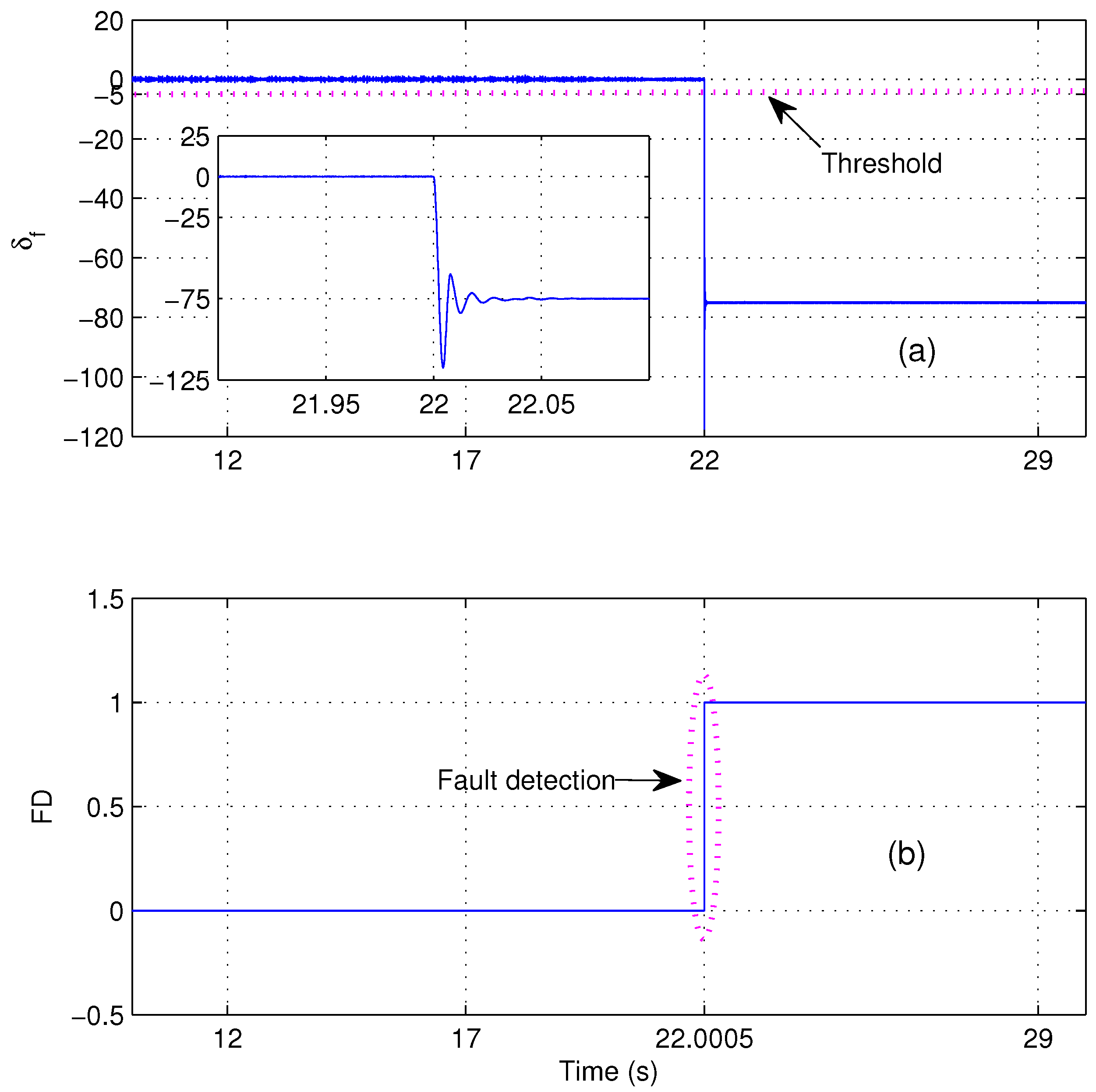
5.3. Experimental Test E 2

The short-circuit fault scenario is considered in this section. Once more, the same varying irradiance condition is emulated in this experiment. This disturbance is visualized through the PV current i p v (Figure 6a), the PV power P p v (Figure 6c) and the inductor current x 2 (Figure 6d). Despite of the varying irradiance condition, the PV voltage x 1 (Figure 6b) is regulated at the MPP (35 V ) through the control signal u (Figure 6e). Meanwhile, the output voltage x 3 (Figure 6f) is kept around 60 V . The short-circuit fault is again triggered at t = 22.0 s . Under this fault condition, the PV voltage x 1 and the PV power P p v go down to zero, as can be seen in Figure 6. On the other hand, the PV current increases up to the short-circuit current. Again, the control signal tries to compensate the fault condition as can be observed in Figure 6e. Nonetheless, the PV voltage x 1 decreases to zero (null PV power), as can be seen from Figure 6b. Meanwhile, the output voltage x 3 is kept at 60 V , as illustrated in Figure 6f. It is worth noting that under this fault condition, the PVM absorbs a peak of power as shown in Figure 6c, which is associated to the storage energy in the passive elements of the boost dc/dc converter. The results of the FI stage for short-circuit fault conditions are illustrated in Figure 7. Here, the FI signal δ ^ f can be observed in the Figure 7a. As can be seen in Figure 7, the FI signal at steady-state decreases up to approximately Δ ^ f = - 75.0 , as expected from the result given in (9). Once more, a constant fault profile can be visualized from Figure 7. Besides, note that the FI signal δ ^ f is not affected by the varying irradiance condition, which implies a varying duty cycle condition. Hence, the FI system is also being evaluated with different duty cycle values. Lastly, as can be observed in Figure 7b, the threshold is selected as T h = - 5 ( T h 6.6 % Δ f ) . As a result, the fault detection time is again approximately 500 μ s, which is equivalent to 8 switching periods.

6. Conclusions

This paper proposed a model-based FI system for SOCSF in a boost dc/dc converter acting as a PV MPPT system. Recently, closed-loop MPPT systems have been suggested in order to maximize the PV energy transferred to the load. Hence, the FI system was designed by taking into account a closed-loop operation of the boost dc/dc converter. The FI system requires only the information demanded by the controller, i.e., no extra sensors are needed in the FI stage. In addition, contrary to the previous results, the proposed FI system was validated against varying irradiance conditions. It should be noted that the efficiency is seriously degraded after SCSF or OCSF is triggered. In fact, the worst case is for an SCSF condition as the PVM absorbs a peak of power. Therefore, a fault reconfiguration strategy can be added to this FI stage [11] for increasing the availability of the global system. Finally, as future work, the proposed FI algorithm will be extrapolated to PV configurations with an MPPT-Distributed scheme.

Acknowledgments

This work is supported by the National Council of Science and Technology (CONACyT) under Research Project: CB-255729-2016 and by PRODEP-UASLP under grant 103.5/15/11048. Part of the work of G. Espinosa-Perez was supported by DGAPA-UNAM under grant PAPIIT IN116516.

Author Contributions

All authors contributed equally to the research described in this work. Diego R. Espinoza Trejo, who concieved and designed the study, also wrote the paper. José E. Hernández Díez, Diego R. Espinoza Trejo and Ernesto Bárcenas performed the experimental results, while Guillermo Bossio and Gerardo Espinosa Pérez supplied guidance and edited the manuscript. All authors read and approved the manuscript.

Conflicts of Interest

The authors declare no conflict of interest.

Abbreviations

The following abbreviations are used in this manuscript:
FIFault identification
SOCSFShort- and open-circuit switch faults
MPPTMaximum power point tracker
PVPhotovoltaic
PDProportional derivative
FDIFault detection and isolation
MPP-STMaximum power point searching technique
MPPMaximum power point
PVMPhotovoltaic module

Appendix A. MPPT Controller Derivation

First, to address the MPPT control problem, the input capacitor voltage is chosen as the control output y 1 = x 1 (voltage-oriented controller). By calculating the derivatives of the output ( y 1 ) the following expressions are obtained:
C p v y ˙ 1 = - x 2 + i p v , L C p v y ¨ 1 = - x 1 + x 3 - x 3 u o + L · D i p v ,
where D ( · ) is the linear differential operator. As can be seen from Equation (A1), the control signal u o appears up to the second derivative. Therefore, the system has a relative degree ρ = 2 in B = x R 3 | x 3 0 . As consequence, the state feedback control law
u o = 1 - x 1 x 3 - 1 x 3 υ
Reduces the input-output mapping to:
L C p v y ¨ 1 = υ + L · D i p v ,
where υ is constructed departing from a proportional-derivative (PD) controller:
υ = k p ( y 1 - y 1 ) + k d ( y ˙ 1 - y ˙ 1 ) + L C p v y ¨ 1 ,
With y 1 = x 1 . As such, y 1 is selected to guarantee the MPP in the PVM. Therefore, by substituting Equation (A4) in Equation (A3), the error dynamics ( x ˜ 1 = x 1 - x 1 ) are described by:
x ˜ ¨ 1 + k d L C p v x ˜ ˙ 1 + k p L C p v x ˜ 1 = 0 .
Hence, Equation (A5) satisfies the characteristic equation given by:
s 2 + k d L C p v s + k p L C p v = 0 .
Asymptotically stability of Equation (A5) is guaranteed simply by considering
k d > 0 & k p > 0 .
However, a desired performance is achieved by matching the error dynamics in Equation (A5) to the following second order system:
s 2 + 2 ξ c ω n s + ω n 2 = 0 .
In Equation (A7), ξ c represents the damping factor and ω n the undamped natural frequency. Therefore, the PD controller gains ( k p , k d ) are defined such that the step response of the system behaves like an overdamped system. Hence, the PD controller gains are chosen as:
k p = 4 N c 2 1 ξ c 2 L C p v f s w 2 k d = 8 N c L C p v f s w
where the settling time t s is considered equal to t s = N c × T s w , where N c 8 and T s w is the switching period [2,6]. By assuming that the voltage reference is a piecewise constant signal ( x ˙ 1 0 ) and by using the differential equation x ˙ 1 given in Equation (1), then the auxiliary control law υ results as:
υ = k p ( y - y ) + k d C p v - 1 x 2 - i p v .
Finally, the term L · D i p v in Equation (A3) is considered as a perturbation, which at steady-state is rejected by the control algorithm. On the other hand, the zero dynamics is characterized by the output capacitor dynamics. Consequently, the equilibrium point of the zero dynamics is asymptotically stable by assuming that the boost dc/dc converter is operating with load.

Appendix B. Observer Gains Selection

As can be observed from Equation (13), the error dynamics is described by a linear time-invariant system. Consequently, as the pair ( F , M ) is observable, then the eigenvalues of ( F - K M ) can be assigned arbitrarily by selecting a vector K . Thus, in the absence of the fault f ˜ = 0 , the origin of the error dynamics Equation (13) is exponentially stable if the matrix ( F - K M ) is Hurwitz. Lastly, by considering f ˜ = 0 , then the characteristic equation is given by:
s 2 + K 1 s + 1 - K 2 L C p v = 0
which is assigned to the standard second-order system
s 2 + 2 ξ o ω n s + ω n 2 = 0 ,
From this, by specifying a desired damping factor ξ o , and a settling time as t s = N o T s w the observer gains presented in Equation (13) are finally obtained.

References

  1. Espinoza-Trejo, D.R.; Bárcenas, E.; Campos-Delgado, D.U.; De Angelo, C.H. Voltage-Oriented Input-Output Linearization Controller as Maximum Power Point Tracking Technique for Photovoltaic Systems. IEEE Trans. Ind. Electron. 2015, 62, 3499–3507. [Google Scholar] [CrossRef]
  2. Kakosimos, P.E.; Kladas, A.G.; Manias, S.N. Fast Photovoltaic-System Voltage or Current-Oriented MPPT Employing a Predictive Digital Current-Controlled Converter. IEEE Trans. Ind. Electron. 2013, 60, 5673–5685. [Google Scholar] [CrossRef]
  3. Martin, A.D.; Cano, J.M.; Silva, J.F.A.; Vazquez, J.R. Backstepping Control of Smart Grid-Connected Distributed Photovoltaic Power Supplies for Telecom Equipment. IEEE Trans. Energy Convers. 2015, 30, 1496–1504. [Google Scholar] [CrossRef]
  4. Ma, S.; Chen, M.; Wu, J.; Huo, W.; Huang, L. Augmented Nonlinear Controller for Maximum Power-Point Tracking with Artificial Neural Network in Grid-Connected Photovoltaic Systems. Energies 2016, 9, 1005. [Google Scholar] [CrossRef]
  5. Robles Algarín, C.; Taborda Giraldo, J.; Rodríguez Álvarez, O. Fuzzy Logic Based MPPT Controller for a PV System. Energies 2017, 10, 2036. [Google Scholar] [CrossRef]
  6. Bianconi, E.; Calvente, J.; Giral, R.; Mamarelis, E.; Petrone, G.; Ramos-Paja, C.A.; Spagnuolo, G.; Vitelli, M. A Fast Current-Based MPPT Technique Employing Sliding Mode Control. IEEE Trans. Ind. Electron. 2013, 60, 1168–1178. [Google Scholar] [CrossRef]
  7. Yang, S.; Bryant, A.; Mawby, P.; Xiang, D.; Ran, L.; Tavner, P. An Industry-Based Survey of Reliability in Power Electronic Converters. IEEE Trans. Ind. Appl. 2011, 47, 1441–1451. [Google Scholar] [CrossRef]
  8. Neeb, C.; Boettcher, L.; Conrad, M.; De Doncker, R.W. Innovative and Reliable Power Modules: A future Trend and Evolution of Technologies. IEEE Ind. Electron. Mag. 2014, 8, 6–16. [Google Scholar] [CrossRef]
  9. Batunlu, C.; Alrweq, M.; Albarbar, A. Effects of Power Tracking Algorithms on Lifetime of Power Electronic Devices Used in Solar Systems. Energies 2016, 9, 884. [Google Scholar] [CrossRef]
  10. Nie, S.; Pei, X.; Chen, Y.; Kang, Y. Fault Diagnosis of PWM DC-DC Converters Based on Magnetic Component Voltages Equation. IEEE Trans. Power Electron. 2014, 29, 4978–4988. [Google Scholar] [CrossRef]
  11. Jamshidpour, E.; Poure, P.; Gholipour, E.; Saadate, S. Single-Switch DC-DC Converter with Fault-Tolerant Capability under Open- and Short-Circuit Switch Failures. IEEE Trans. Power Electron. 2015, 30, 2703–2712. [Google Scholar] [CrossRef]
  12. Farjah, E.; Givi, H.; Ghanbari, T. Application of an Efficient Rogowski Coil Sensor for Switch Fault Diagnosis and Capacitor ESR Monitoring in Nonisolated Single-Switch DC-DC Converters. IEEE Trans. Power Electron. 2017, 32, 1442–1456. [Google Scholar] [CrossRef]
  13. Ribeiro, E.; Marques Cardoso, A.J.; Boccaletti, C. Fault-Tolerant Strategy for a Photovoltaic dc/dc Converter. IEEE Trans. Power Electron. 2013, 28, 3008–3018. [Google Scholar] [CrossRef]
  14. Ribeiro, E.; Marques Cardoso, A.J.; Boccaletti, C. Open-Circuit Fault Diagnosis in Interleaved dc/dc Converters. IEEE Trans. Power Electron. 2014, 29, 3091–3102. [Google Scholar] [CrossRef]
  15. Jamshidpour, E.; Poure, P.; Saadate, S. Photovoltaic Systems Reliability Improvement by Real-Time FPGA-Based Switch Failure Diagnosis and Fault-Tolerant dc/dc Converter. IEEE Trans. Ind. Electron. 2015, 62, 7247–7255. [Google Scholar] [CrossRef]
  16. Yan, X.G.; Edwards, C. Nonlinear robust fault reconstruction and estimation using a sliding mode observer. Automatica 2007, 43, 1605–1614. [Google Scholar] [CrossRef]
  17. Poon, J.; Jain, P.; Konstantakopoulos, I.C.; Spanos, C.; Panda, S.K.; Sanders, S.R. Model-Based Fault Detection and Identification for Switching Power Converters. IEEE Trans. Power Electron. 2017, 32, 1419–1430. [Google Scholar] [CrossRef]
  18. Chen, J.; Patton, R.J. Robust Model-Based Fault Diagnosis for Dynamic Systems; Springer Science+Business Media: New York, NY, USA, 1999. [Google Scholar]
  19. Mahmoud, Y.; Xiao, W.; Zeineldin, H.H. A Simple Approach to Modeling and Simulation of Photovoltaic Modules. IEEE Trans. Sustain. Energy 2012, 3, 185–186. [Google Scholar] [CrossRef]
  20. Khalil, H.K. Nonlinear Systems, 3rd ed.; Prentice Hall: Upper Saddle River, NJ, USA, 2002. [Google Scholar]
  21. Tobón, A.; Peláez-Restrepo, J.; Villegas-Ceballos, J.P.; Serna-Garcés, S.I.; Herrera, J.; Ibeas, A. Maximum Power Point Tracking of Photovoltaic Panels by Using Improved Pattern Search Methods. Energies 2017, 10, 1316. [Google Scholar] [CrossRef]
  22. Chao, K.H.; Wu, M.C. Global Maximum Power Point Tracking (MPPT) of a Photovoltaic Module Array Constructed through Improved Teaching-Learning-Based Optimization. Energies 2016, 9, 986. [Google Scholar] [CrossRef]
  23. Alajmi, B.N.; Ahmed, K.H.; Finney, S.J.; Williams, B.W. A Maximum Power Point Tracking Technique for Partially Shaded Photovoltaic Systems in Microgrids. IEEE Trans. Ind. Electron. 2013, 60, 1596–1606. [Google Scholar] [CrossRef]
  24. Lyden, S.; Haque, M.E. Maximum Power Point Tracking techniques for photovoltaic systems: A comprehensive review and comparative analysis. Renew. Sustain. Energy Rev. 2015, 52, 1504–1518. [Google Scholar] [CrossRef]
Figure 1. Boost dc/dc power converter as a Photovoltaic Maximum Power Point Tracker (PV MPPT) system with fault tolerance capability, [11].
Energies 11 00616 g001
Figure 2. Fault identification system for a boost dc/dc converter.
Energies 11 00616 g002
Figure 3. Experimental Test Bench.
Energies 11 00616 g003
Figure 4. Experimental test E 1 by considering varying irradiance and open-circuit fault conditions. (a) PV current i p v ; (b) PV voltage x 1 = z 11 and PV voltage estimation z ^ 11 ; (c) PV power P p v ; (d) inductor current x 2 = z 12 and inductor current estimation z ^ 12 ; (e) control signal u; (f) output voltage x 3 .
Energies 11 00616 g004
Figure 5. Open-circuit switch fault (OCSF) Identification for experimental test E 1 : (a) FI signal δ ^ f ( t ) and (b) fault detection signal (FD).
Energies 11 00616 g005
Figure 6. Experimental test E 2 by considering varying irradiance and short-circuit fault conditions. (a) PV current i p v ; (b) PV voltage x 1 = z 11 and PV voltage estimation z ^ 11 ; (c) PV power P p v ; (d) inductor current x 2 = z 12 and inductor current estimation z ^ 12 ; (e): control signal u; (f) output voltage x 3 .
Energies 11 00616 g006
Figure 7. Short-circuit switch fault (SCSF) Identification for experimental test E 2 : (a) FI signal δ ^ f ( t ) and (b) fault detection signal (FD).
Energies 11 00616 g007
Table 1. Proportional-Derivative (PD) Controller and Observer Parameters.
ParameterValueParameterValue
k p 134.15 k d C p v - 1 71.5
k 1 15 × 10 3 k 2 - 56 × 10 3

