Electromagnetic Design and Losses Analysis of a High-Speed Permanent Magnet Synchronous Motor with Toroidal Windings for Pulsed Alternator

School of Electrical Engineering and Automation, Harbin Institute of Technology, No. 2 Yikuang Street, Nangang District, Harbin 150080, China
*
Author to whom correspondence should be addressed.
Energies 2018, 11(3), 562; https://doi.org/10.3390/en11030562
Submission received: 31 December 2017
/
Revised: 28 February 2018
/
Accepted: 2 March 2018
/
Published: 6 March 2018
(This article belongs to the Special Issue Electric Machines and Drives for Renewable Energy Harvesting 2017)
Abstract
:The configuration of conventional high-speed Permanent Magnet Synchronous Motors (PMSMs) is usually long and thin, with overlong axial end winding lengths, which is not suitable for those applications that place severe restrictions on the axial length, such as pulsed alternators. This paper first studied the key design aspects of a flat-structure high-speed PMSM. The toroidal-windings, low-conductivity material of the retaining sleeve, large airgap and segmentation of magnets were studied to reduce the axial length of the motor. The division of the stator and the employment of a non-magnetic outer stator were used to improve overall performance. Then the losses of the prototype were calculated and the factors having an influence on the losses were also investigated, after which, their effects on the total loss were evaluated. The total loss could be effectively reduced by the decrease of strand number of conductors and the division of stator, while only being slightly reduced by epoxy resin pole fillers. Metal-stack pole fillers have the same effect on the reduction of rotor loss as epoxy resin, while maintaining the good thermal-conductivity of metal. In addition, the influence of the carrier frequency of the inverter on the losses was analyzed, and it was found that high carrier frequency was helpful to reduce rotor losses. Finally, a small-scale prototype was manufactured and the experimental results were provided.
1. Introduction
Pulsed alternators are widely considered for driving electromagnetic railguns. Utilizing a primary motor to accelerate the high-speed rotor of the pulsed alternator to store the mechanical energy, it can discharge several megampere currents in a few milliseconds [1,2]. To reduce the axial length of the power, the prime motor should be designed as a flat structure [3].
Nowadays surface-mounted PMSMs are increasingly used for high-speed applications, because of the merits of simple structure and high-strength of the rotor [4,5]. The number of poles is usually designed as two or four to reduce the iron losses at high operating frequency [6]. With conventional lap windings, the overlong axial length of the end windings is unavoidable for motors of a small number of poles. This will not only result in an increase of the volume, but also problems of rotor dynamics. It will cause excessive acoustic noise emissions, high bearing loss, and even catastrophic failure of the system for a slender rotor, when the operating speed of the rotor exceeds the critical speed [7,8]. Toroidal windings have been used to reduce the axial length of the motor [9], but slotting on the outer edge of the stator will decrease the heat-dissipation capability of the motor. Besides, the windings in the outer slots increase the copper loss, which will further increase the heat dissipation difficulty. In addition, the retaining sleeves are designed thicker to improve the rotor strength, in order to withstand the high decelerations encountered during the discharge of pulsed alternator [10,11]. This will cause a huge heat dissipation challenge for the rotor due to the poor cooling conditions of the rotor [12,13], so it’s necessary to study the electromagnetic design of high-speed PMSMs with flat structures and optimize the losses.
The proximity and skin losses of the windings should be considered in high-frequency machines. Two-dimensional (2-d) analytical models were proposed to analyze the proximity losses for Permanent Magnet (PM) machines in high-speed operation [14]. The AC loss was much bigger than the DC copper loss. Induced by PWM excitation, the higher-frequency harmonic current will further increase the proximity loss. The influence of PWM on the proximity loss was analyzed for a PM brushless AC machine. The results showed that the skin and proximity losses were significantly increased, and this was confirmed both by theoretical calculations and experiments [15,16]. To predict the iron loss of high-frequency machines accurately, an iron loss model of the elliptical field was proposed, which can take the rotating magnetization into consideration [17,18], but it’s difficult to acquire the corresponding loss coefficients for the rotating magnetization model. Hence, an improved loss separation model, based on the two equivalent orthogonal alternating flux density components by using only alternating loss data, was then proposed. Based on the improved model, the no-load iron losses in the induction motor was predicted with satisfactory accuracy [19]. The electromagnetic losses of the rotor, consisting of the eddy-current losses of the magnets, retaining sleeve and pole fillers, make up a small portion of the total loss of the motor. But the heating problem of the rotor becomes even worse for the rotor wrapped with the carbon-fiber composite sleeve and powered by PWM inverter, because of the poor property of thermal conductivity and the increased rotor loss [20,21]. 2-d FEA and analytical field analysis methods were used to calculate the rotor losses. The technologies of magnet segmentation, new sleeve materials and structures were developed to reduce the eddy-current losses of the rotor [22,23,24,25]. The influence of the carrier frequency of the PWM inverter on the rotor loss was investigated by 3-d FEA method to improve the accuracy of the calculation [26].
In this paper, the key design features of a flat-structure high-speed PMSM were first studied, and a prototype with toroidal windings was designed. Then the copper loss, iron loss, rotor eddy-current losses of the prototype were calculated, based on the advanced methods, respectively, and the factors having an influence on the losses were also investigated. After that, their effects on the total loss were evaluated. Moreover, the influence of the carrier frequency of the PWM inverter on the losses was analyzed. Eventually, a small-scale prototype was manufactured and the experimental results were provided to verify the theoretical analysis.
2. Electromagnetic Design
The rated parameters of the prototype were 300 kW, 12,000 rpm. It was used to accelerate a 50-MJ alternator. The main dimensions of prototype can be expressed as [6]:
where Di is the inner diameter of the stator, Lef is the effective length, P′ is the apparent power, ap′ is the effective pole arc coefficient, KNm is the air-gap flux factor, Kdp is the stator winding factor, A is the electric loading, Bδ is the airgap flux density, nN is the rated speed.
Tangential speed of the rotor is a key criterion for the high-speed motor. It is generally restricted by the mechanical strength of the material of the rotor core. The centrifugal force at the outer edge of the rotor is expressed as:
where ρ is the density, v is the tangential speed at the outer edge of the rotor, [σ] is the allowable stress of the rotor. The terms ω, Dr are the angular velocity and outer diameter of the rotor, respectively. According to the allowable stress of the rotor core, the maximum diameter can be determined and Di can also be acquired. According o Equation (1):
The eddy-current loss of the rotor is caused by the asynchronous magnetic field of the airgap with respect to rotor, which results from the airgap permeance variation due to stator slotting, space harmonics of winding distribution and time harmonic components of the armature current. The eddy-current loss in the sleeve or magnets can be expressed as [23]:
where P is the eddy-current loss of the sleeve or magnets, ρ is the resistivity of the sleeve or magnets, rm and h are the mean radius and thickness of the sleeve or magnets, respectively, Bk is the amplitude of harmonic flux density at the region of sleeve or magnets, ωk is the relative speed between harmonics and rotor, k is the order of the harmonic. When all the dimensions of the cross-section for the prototype are fixed, the percentage of each harmonic flux density in the airgap flux density is certain, regardless of the value of the airgap flux density, so the eddy-current loss of the rotor can be further written as:
where Ploss is the eddy-current loss of the rotor. The loss density of the rotor can be expressed as:
where ρloss is the loss density of the rotor. The maximum allowable loss density of the rotor is limited with the given cooling method.
where ρmax is the maximum allowable loss density of the rotor. When the rotor loss density is higher than the allowable value, Bg should be decreased to reduce the rotor loss density, which will cause the increase of the axial length and decrease of the power density. Material of sleeve, airgap length and segment number of magnets were analyzed to reduce the axial length.
2.1. Windings
Double-layer lap windings are widely used in high-speed PMSMs, but they usually have long end windings. Toroidal windings were considered as a way to reduce the axial length of the motor, since they were like toroids around the stator, the axial length of the end windings could be made very short. Concentrated windings were also considered for the shorter length of end windings. The configurations of windings are shown in Figure 1a–c, respectively. 35WW250 and B20AT1500 were analyzed for the design of the prototype to reduce the high-frequency iron loss. Figure 1d shows the curves plotted of the iron loss versus flux density for the two materials, with the frequencies of 400 Hz and 1000 Hz. It can be seen that the iron loss of 35WW250 was much higher than B20AT1500, at the same frequency and flux density. Normally, a value of 31 W/kg was given as an acceptable limit for silicon steel sheet [27]. Beyond this limit, the cooling of the metal core poses a problem. Within this limit, the largest value of flux density is about 0.5 T, at the 1000 Hz level for 35WW250, but which is too low for the motors. For this reason it is usually used in low and medium frequency motors. In contrast, the largest value of flux density is about 0.8 T at the 1000 Hz level for B20AT1500. The B-H curves of the two materials were given in Figure 1e.
Within the limit of the iron loss density, four designs of the prototype were provided in Table 1. Do is the outer diameter of the stator. Case 1 used double-layer lap windings, case 2 and 3 used toroidal windings, and case 4 used concentrated windings. It can be seen the axial length of windings of case 1 was 290 mm, which was longer than case 2–4 of 180 mm, decreased by 37.9%. 35WW250 was used as the stator materials for the first two cases, and it was replaced by the low-loss silicon steel sheet of B20AT1500 for cases 3 and 4. As can been seen, the volume of case 2 was reduced by 7.1% compared to case 3 by replacing 35WW350 with B20AT1500.
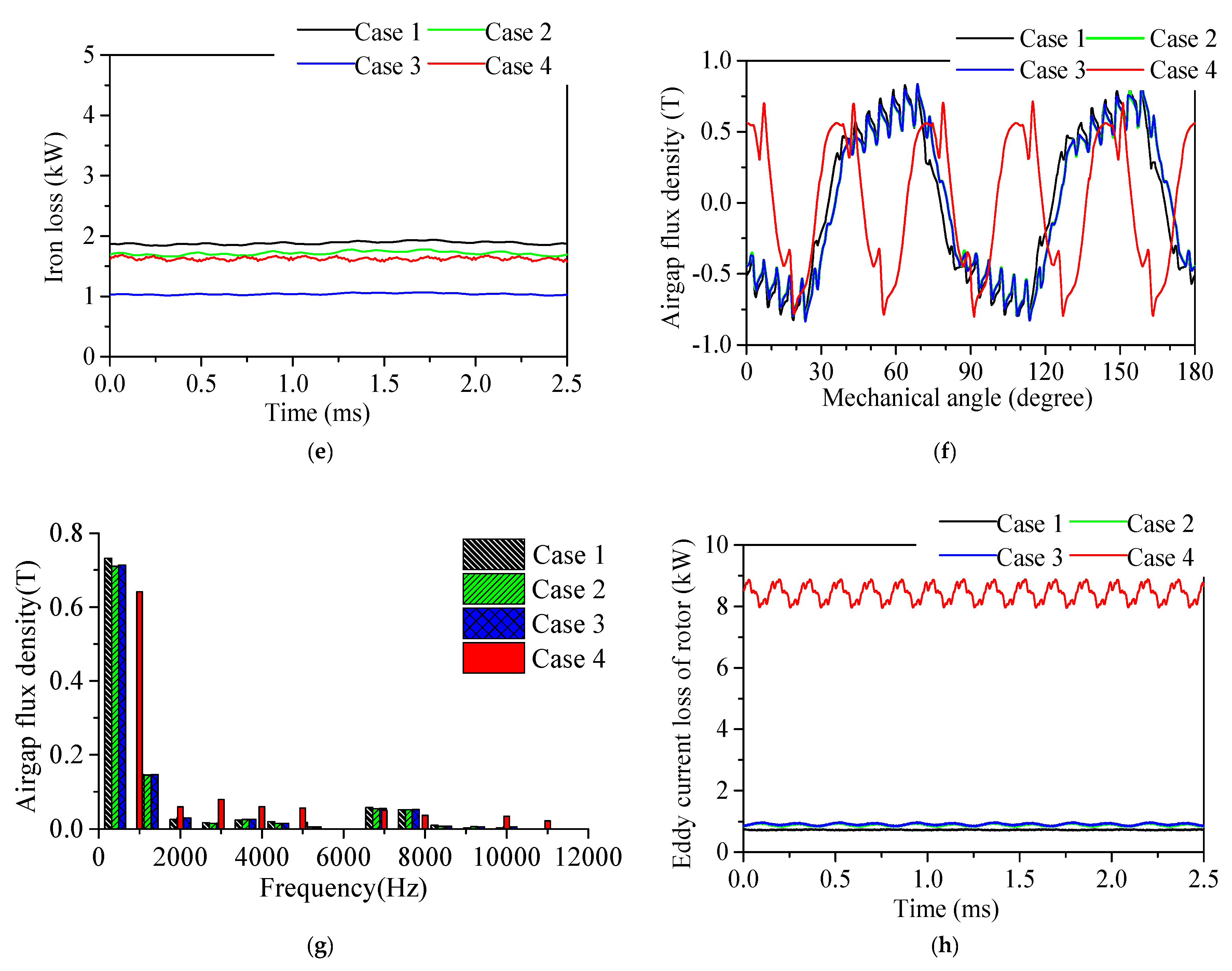
A 2-d time-stepping FEA method was used to analyze the electromagnetic performance of the prototype. The iron loss was calculated by the classic loss separation model of Bertotti, as seen in Equation (8). Here, Kh, Kc, Ke, are coefficients of hysteresis loss, eddy-current loss, and excess loss for the silicon steel sheet, respectively. f and Bm are the alternating frequency and amplitude of the magnetic flux density. By curve fitting the iron loss characteristics of the materials provided in Figure 1d, the loss coefficients are found to be 269.8, 0.403, 0.3965 for 35WW250, while they are 115.51, 0.211, 0.8441 for B20AT1500. Figure 2a–d show the FE meshes and the distributions of the flux lines and densities for the four prototypes. More leakage flux lines were observed between the poles of case 4 than the other three cases, as well as in the slot openings. The flux density of case 3 was higher than case 2 on the basis of similar value of the average iron loss density. Figure 2e shows the iron losses for the four prototypes. With low-loss silicon steel sheet, the iron loss of case 3 was smaller than case 2. The iron loss of case 4 was the highest among the four cases owing to the high operating frequency. The iron loss densities were calculated in Table 1. The radial flux densities in the middle of the airgap were plotted in Figure 2f, and the waveforms were highly distorted. Harmonic spectrum images corresponding to the radial flux density were provided in Figure 2g. As can be seen, the amplitude of the working harmonic flux density of case 4 was lower than the other cases with the same thickness of magnet, because of the fact that there was more leakage flux between the poles and in the slot openings. Besides, more high-frequency harmonics were included in case 4, ranging from 2000 to 11,000 Hz, which would have resulted in eddy-current loss in the rotor. As a result, the eddy-current losses of case 4 were much higher than the first three cases as shown in Figure 2h. And it became the dominant loss of motor, which will have resulted in overheating problems. In addition, both the efficiency and power factor of case 4 were lower than the other three cases as shown in Table 1. With the same material for the stator, the power density of case 2 was lower than case 1, while case 3 was lower than case 4, due to the increased mass of the outer teeth for the cases with toroidal windings. In contrast, the power density of a similar high-speed PMSM of a 1.12 MW, 18,000 rpm was 1.4 kW/kg (6). Consequently, four poles and toroidal windings were chosen for the prototype. Lap windings are not suitable for those applications that have any strict requirement on the axial length of the motor for the long end windings. Even though concentrated windings have short end windings, they are typically not suitable for the application due to higher eddy-current loss of the rotor.
2.2. Stator Structure
The distribution of flux lines of the prototype with toroidal windings at rated load was shown in Figure 3a. Some leakage flux lines can be seen around the outer slots. So the flux circuit was modified by the windings in the outer slots of the stator, and it will have resulted in the degradation of electromagnetic performance. Thus, the stator of the prototype was divided into two parts: inner stator and outer stator shown in Figure 3b.
The inner stator was exactly the same with the conventional stator both in the structure and function, the outer stator was made of non-magnetic materials to solve the problem of flux leakage and functioned only for placement of the windings. Aluminum alloy (al-alloy) and epoxy glass cloth laminate sheet were successively considered for the manufacture of the outer stator. The distribution of the flux lines of the prototype, with a non-magnetic outer stator at rated load, was also shown in Figure 2b. The problem of the leakage flux around the outer slots was approximately solved. So the influence of windings in the outer slots on the electromagnetic performance of the prototype could be ignored. From the calculations done, the power factor was increased from 0.9672 to 0.9761 and 0.9729 for the outer stator of al-alloy and epoxy glass cloth laminate sheet, respectively.
2.3. Retaining Sleeve
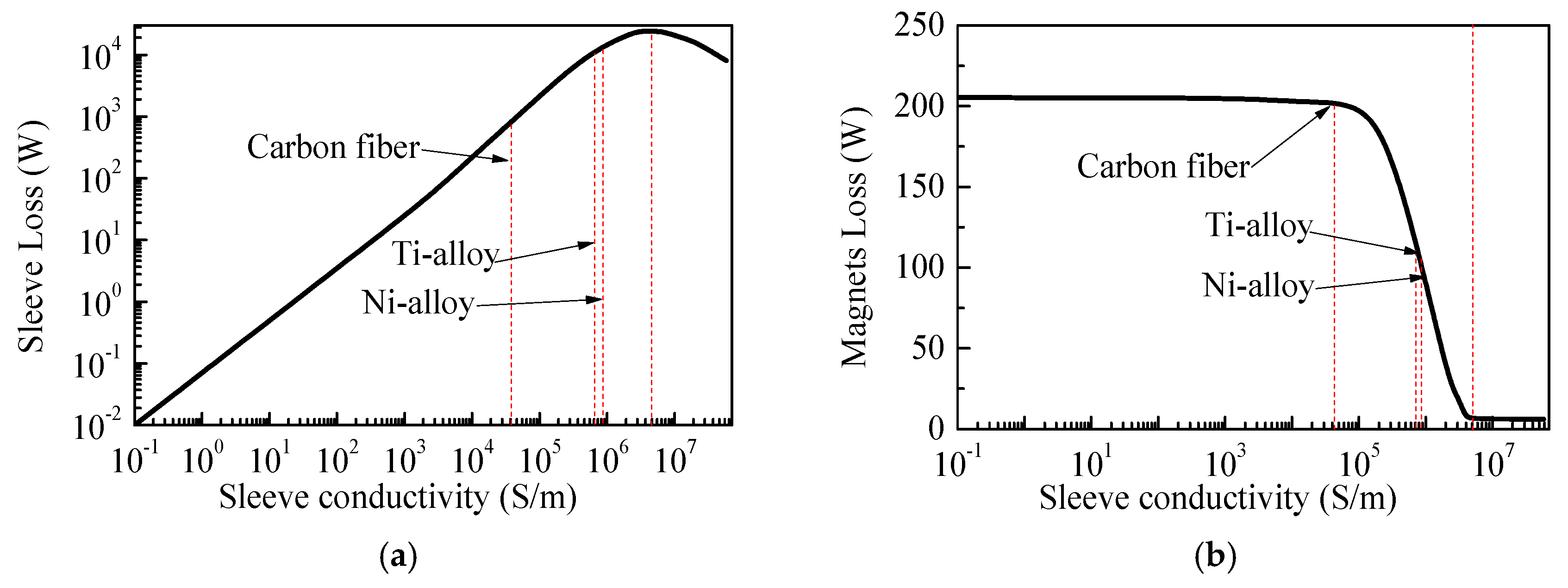
In order to shield the harmonic magnetic field in the rotor, an eddy current will be induced in the retaining sleeve and magnet, resulting in eddy-current losses. Based on the above 2-d FEA methods, the influences of the conductivity of the retaining sleeve on the losses of the sleeve and magnets are illustrated in Figure 4a,b, with the thickness of the sleeve being 10 mm. The conductivity of the magnets was 6.25 × 10⁵ S/m. As can be seen, the eddy-current loss of the sleeve first increases proportionally with the conductivity, when conductivity is lower than 4 × 10⁶ S/m, and then decreases with the conductivity. The reason is that the shielding effect of the harmonic magnetic field of the sleeve first increases with conductivity, so that the eddy current of the sleeve increases proportionally with conductivity, whereas the resistance of the sleeve decreases proportionally with conductivity, consequently, the eddy-current loss of the sleeve (product of the square of the current and resistance) increases proportionally with the conductivity. When the conductivity is higher than 4 × 10⁶ S/m, the harmonic magnetic field is completely shielded, the shielding effect of the sleeve no longer increases with conductivity, so the induced current can be viewed as constant, whereas the resistance still decreases proportionally with conductivity, so the eddy-current loss decreases with the conductivity. The changes of the eddy-current loss of the magnets with respect to conductivity are very little, when conductivity is lower than 105 S/m, because of the poor shielding effect of the harmonic magnetic field of the sleeve. As the shielding effect of the sleeve increases with conductivity, the harmonic magnetic field penetrating into the magnets decreases, so the eddy-current loss of magnets then decreases greatly. The loss of the magnets can be ignored with conductivity ranges larger than 4 × 10⁶ S/m, since the harmonic magnetic field penetrating into magnets has been completely shielded.
Nickel alloy (Ni-alloy), titanium alloy (Ti-alloy) and carbon fiber are three typical materials for use with the retaining sleeve at present, they are marked in the figures. It can be seen that the magnet losses of the rotor with Ni-alloy and Ti-alloy sleeve are about half of that of the carbon fiber sleeve, but the sleeve losses are 20 times more than that of the carbon fiber sleeve. The rotor loss with Ni-alloy or Ti-alloy sleeve is about three times more than stator loss, which will cause the overheating of the motor. To reduce the rotor loss density, the airgap flux densities should be decreased according to Equation (6). With the inner diameter of the stator fixed, the axial length of the motor will be increased to maintain the output and the torque density will be decreased. As a result, the low-conductivity carbon-fiber was beneficial improving the torque density and decreasingthe axial length of the motor, and so was chosen as the material of the retaining sleeve.
2.4. Airgap
Table 2 presents the performances of the prototype with the airgap length of 1, 2, 3, 4 mm, calculated by 2-d FEA method. In order to maintain the rated output, the thickness of the magnets was increased with the increase of the airgap length. As can be seen, the corresponding thicknesses of magnets were 16, 18, 20, 22 mm, respectively.
The distributions of the radial airgap flux density at the surface of the rotor, in no-load and rated-load conditions, were shown in Figure 5a,b. The root mean square (RMS) values of the radial airgap flux density were almost identical, with different lengths of the airgap. The no-load electromotive force (EMF) and rated current were also almost the same, as shown in Table 2. Besides, the flux density distributions showed a characteristic dip in correspondence to each slot opening. As the airgap length increased, the dip became smaller, which meant the harmonic flux density caused by the stator slotting was reduced. Moreover, the amplitude of harmonic flux density, due to space harmonics of winding distribution and time harmonic components of the armature current, would also decrease with the increasing the airgap length, because of the increase of the magnetic resistance in the airgap. Figure 5c shows the harmonic spectrum images corresponding to Figure 5b. The fundamental amplitudes were almost the same, while the amplitudes of the harmonics decreased with the airgap length, which agreed well with above analysis. According to Equation (4), the eddy-current loss of the rotor loss could be reduced. The eddy-current losses of the carbon fiber sleeve and magnets induced by the harmonic flux density were plotted in the Figure 5d. Both the sleeve and magnet losses decreased with the length of the airgap. The loss densities were computed and decrease with the airgap length, shown in Table 2. The cooling capacity was limited for a certain rotor, so the loss density would be within the maximum allowable value, otherwise the rotor will have overheated. With the given length of airgap, the flux density of the airgap would have to be decreased in order to reduce the rotor loss density according to Equation (6), when it exceeds the maximum allowable value, and which will in turn increase the volume of the motor in Equation (1). Alternatively, the loss densities could also be reduced by an increase of the airgap length and thickness of the magnets, without affecting the volume. However, there was the dilemma that the intensity of PM utilization was greatly increased, as shown in Table 2. As a comparison, it was 0.0167 kg/kW for a similar motor as illustrated in [6]. Besides, a thicker sleeve was called for in order to ensure the rotor strength remained the same, which will have further increased the difficulty of dissipation of heat for the rotor. Therefore, the increase of the airgap length is helpful to improve the torque density, and to decrease the axial length of a high-speed motor with flat structure, but at the expense of consuming more magnets. Finally, a 2-mm airgap was chosen for the prototype.
2.5. Segmentation of Magnets
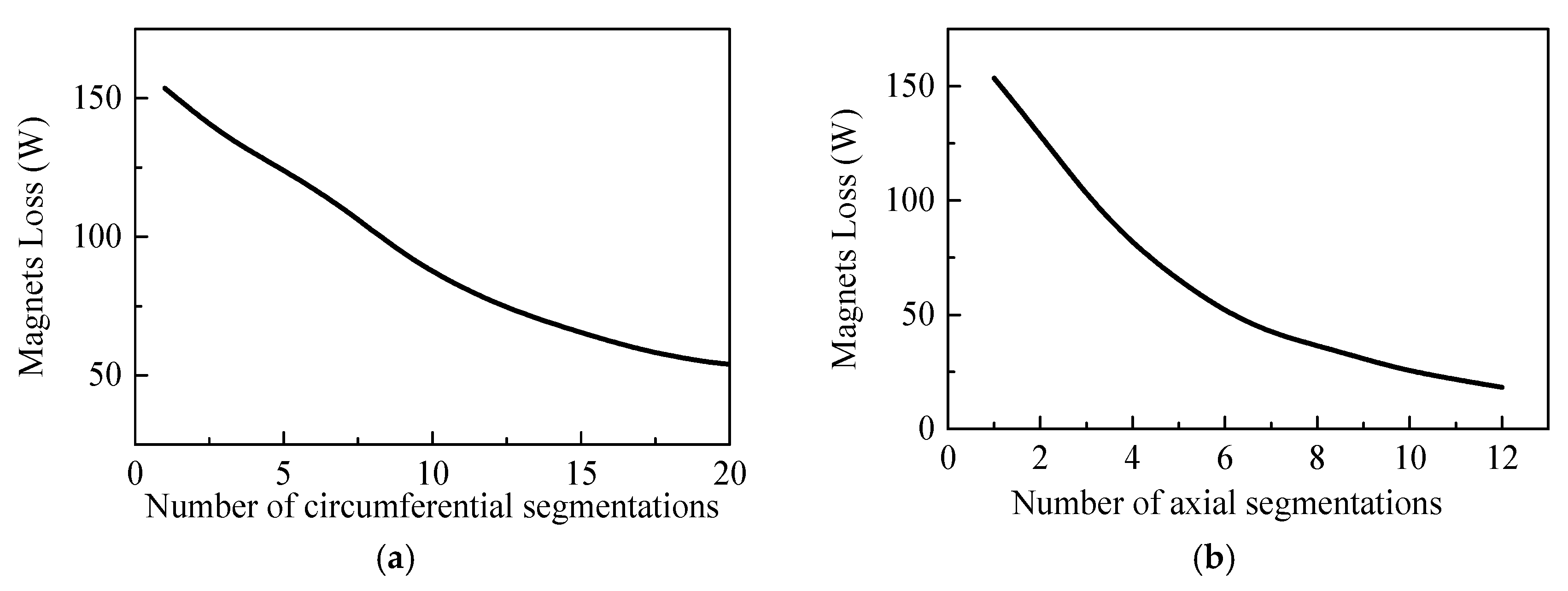
Circumferential and axial segmentations of permanent magnets were analyzed to reduce the eddy-current loss of magnets, based on the 3-d finite element (FE) model in Section 3.2. The variations of magnet loss with the number of circumferential and axial segments were plotted in Figure 6a,b.
As the number of circumferential and axial segments increases, the magnet loss decreases gradually. It means the airgap flux density can be increased with the increase of the segment number of magnets, within the maximum allowable loss density of the rotor. With the fixed diameter of the stator, the axial length of the motor will be decreased with the segment number. When the circumferential number of segments is larger than 15, the loss change becomes very small as the number increases. The loss of magnets circumferentially divided into 20 segments is nearly 35.1% of that not segmented. Likewise, the loss change becomes very small as the number increases, when the axial number of segments is larger than six. The loss of the magnets that was axially divided into 12 segments is nearly 11.9% of that not segmented. Nevertheless, the magnets cannot be divided into too small size, because it is probably fragile during the process of assembly. Thus, considering the manufacturing feasibility, the magnets were circumferentially divided into five segments, and the magnet loss was reduced by 19.1% compared with that of the non-segmented. Though the axial segment of the magnets was very effective to reduce their eddy-current loss, the axial divisions were not implemented for the prototype in order to simplify the manufacturing process.
2.6. Electromagnetic Performances
The configuration of the prototype is provided in Figure 7a and the specifications are listed in Table 3. Pole fillers were assembled between the magnets to improve the strength of the rotor. The disks were used to fix the magnets axially. The waveform of the rated torque was shown in Figure 7b. The torque ripple was about 1%. The waveforms of the line back EMF, at no load, were shown in Figure 7c. The total harmonic distortion (THD) was about 0.84%. The waveforms of rated currents were shown in Figure 7d. The THD of the current curve was only about 0.44%, hardly with any harmonics component. Thus, the prototype showed good electromagnetic performance.
3. Analysis of Losses and Evaluation of Effects of Influencing Factors
3.1. Copper Loss
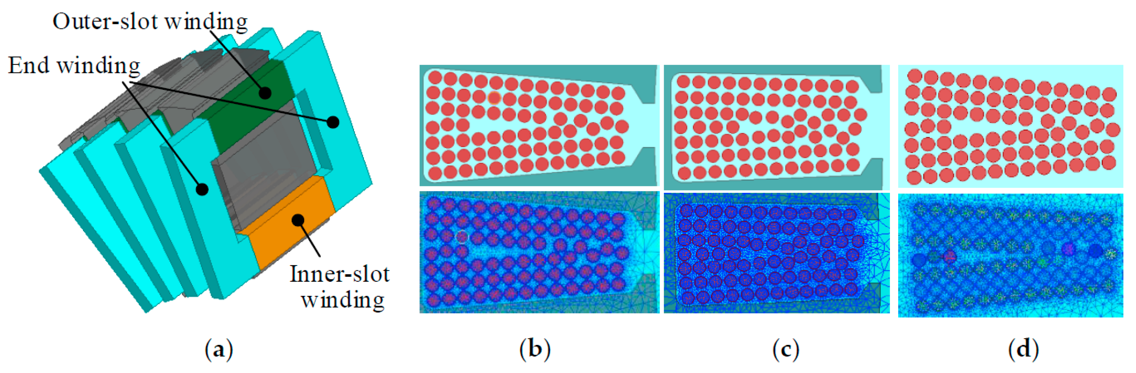
The AC loss of the windings is greatly dependent on the density of the magnetic field and the frequency at the location of the windings. As the density of the magnetic field is considerable stronger in the iron core slots, whereas very small in the air, the inner slot windings and end-windings losses need to be calculated separately. The toroidal windings were divided into three parts: the windings in the inner slots (inner-slot-wingdings), the windings in the outer slots of stator (outer-slot-wingdings), and the remaining part of the windings (end-windings), shown in Figure 8a. The strand number of each conductor was 15. The 2-d FEA models of conductors in one inner slot, outer slot and end windings were built and meshed as Figure 8b–d. Based on the models, the copper losses of the three parts were calculated and are given in Table 4, respectively, with the outer stator material of silicon steel sheet, al-alloy and epoxy glass cloth laminate. It can be seen that the end-windings loss accounts for the majority of the copper loss for the prototype. Compared with the outer stator material of silicon steel sheet, the copper loss was decreased by 226.4 W, about 10.4%, after replacement of the outer stator material with al-alloy or epoxy glass cloth laminate. And the AC copper loss was 17.4%, larger than the DC loss.
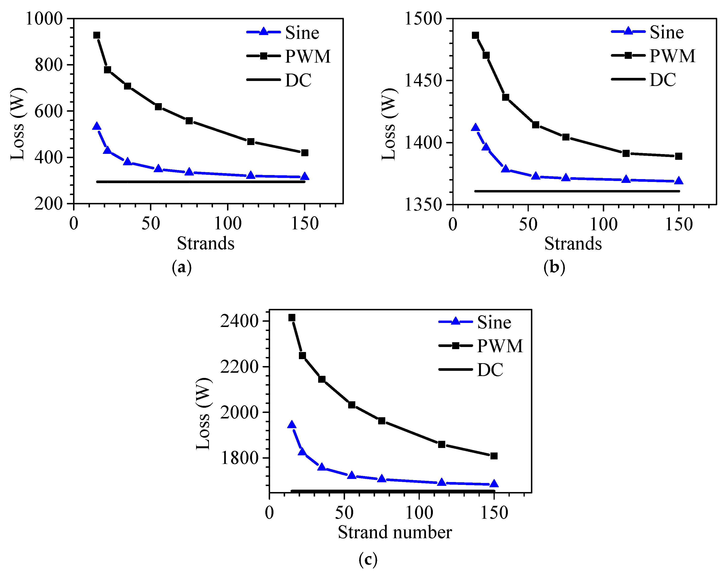
With the outer stator material of al-alloy or epoxy glass cloth laminate, the leakage magnetic field in the outer slot caused by the windings is comparable to that in the air, so the outer-slot-windings loss was included in the end-windings loss for the following analysis. The variation of copper loss with respect to strand number of the conductors was investigated under sinusoidal voltage and 8-kHz carrier-frequency PWM excitations, and then compared with DC loss as well, shown in Figure 9. The strand number of the conductors ranges from 15 to 150, so the corresponding diameters of the wire are from 2.26 mm to 0.71 mm, maintaining the same section area for the conductors. It can be seen that the copper loss powered by PWM excitation is much higher than sine excitation. The copper loss will be largely underestimated, without taking proximity and skin losses into consideration.
Under the sinusoidal voltage excitation, the copper loss decreases with the increase of strand number and the change slows down gradually. The copper loss for the slot-in-windings was decreased by 216.5 W, about 68.7%, while the end-windings loss will have been decreased by 43 W, about 3.1%, and the total copper loss will have been decreased by 15.4%, when the strand number increases from 15 to 150. The reduction of the copper loss is mainly contributed by the slot-in-windings. The change of copper loss is very small and can be ignored, when the strand number is larger than 55. Under the PWM excitation, the influence of increasing strand number on the copper loss is more obvious. And the change of copper loss is still large even when the strand number is larger than 55. The copper loss for the inner-slot-windings will have been decreased by 199 W, about 32.2%, while the end-windings loss will have been decreased by 25 W, about 1.8%, and the total windings loss will have been decreased by 11%, when the strand number increases from 55 to 150. Therefore, the copper loss can be further reduced by decreasing the strand number of the conductors under PWM excitation.
3.2. Iron Loss
The magnetization of the stator core consists of alternative magnetization and rotating magnetization. Most of the traces of magnetic flux lines are distorted elliptically rotating flux. The classic loss separation model of Equation (8) was based on the alternative magnetization and widely used in low-frequency motors for accuracy results. However, it may underestimate the iron loss in high-frequency machines, so the improved model was built as shown in [18]:
Here, Br and Bθ are the radial and circumferential components of the elliptically rotating flux density vector, and Bkmaj and Bkmin are the harmonic amplitudes of Br and Bθ, k is the harmonic order. On the basis of the improved iron loss model, the iron losses of the prototype were computed, as shown in Table 5, with the outer stator material of silicon steel sheet, al-alloy and epoxy glass cloth laminate, respectively. The iron loss is thus the least with the use of silicon steel sheet as outer stator material.
Due to the alternative leakage flux formed by the outer-slot-windings, additional eddy-current losses would be induced in the metal housing, as well as the outer stator of al-alloy. With a 20-mm thickness stainless steel housing, the losses in the housing and outer stator were also calculated in Table 5 by 3-d FEA method. Figure 10a shows the 3-d FE mesh model of the prototype, which is 1/8 of the whole region due to the symmetry. Figure 10b shows the distribution of eddy current generated in the outer stator and shell with the al-alloy outer stator. As can be seen in Table 5, the housing loss is highest with the outer stator made of silicon steel sheet. Although no eddy-current loss is generated in the outer stator of epoxy glass cloth laminate, the housing loss is still huge. Considering the poor thermal conductivity of epoxy glass cloth laminate, the losses are impossible to be dissipated by water-cooling of the housing. By contrast, the housing loss with the outer stator of al-alloy is lowest, and the outer stator loss can be conducted quickly to the housing. Therefore, al-alloy was thought to be the wisest choice of material for the outer stator.
3.3. Eddy-Current Loss of the Rotor
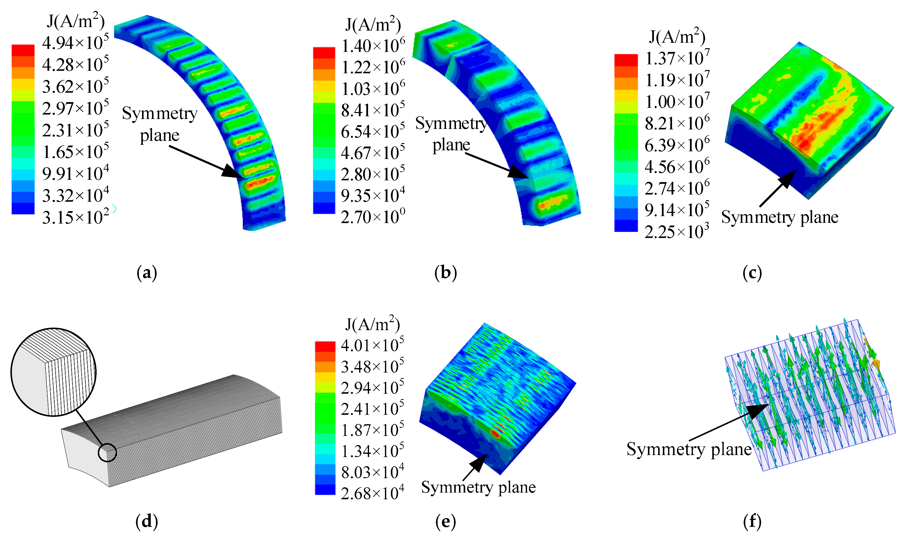
The eddy-current losses of the rotor were also analyzed based on the above 3-d FE model to take account of the influences of the variation of the eddy current of the rotor along the axial direction. With al-alloy pole fillers, the distributions of the eddy-current density on the sleeve, magnets and pole fillers were provided for the one-eighth model in Figure 11a–c. Several rings of the eddy current can be observed on these components. The density of the current is lower on the ends than middle. Due to the good conductivity of al-alloy, the density of current of the filler is higher than the sleeve and magnets. Ti-alloy, stainless steel (s-steel) and epoxy resin were also considered as candidates to reduce the eddy-current loss of the fillers. As can be seen in Table 6, the filler losses are a little different, as given for the three metal fillers. The rotor eddy-current loss is least with epoxy resin pole fillers. But the thermal conductivity of resin pole fillers is poor, so it is not helpful for heat dissipation in the rotor. With the advantageous property of mechanical strength and thermal conductivity, metal materials are competitive as pole fillers. To reduce the eddy-current loss of the metal pole fillers, and to maintain the beneficial properties of metal, metal stack technology was employed. The configuration of the metal-stack pole filler was exhibited in Figure 8d. It was made up of thin sheets of metal, which were glued under compression with a high-temperature adhesive to achieve the axial resistivity. The losses of the pole fillers constructed by 2-mm s-steel stack and 1-mm, 2-mm al-alloy stack were computed in Table 6. As a result, the eddy-current loss of pole fillers could be ignoredin the 2-mm s-steel stack and 1-mm al-alloy stack. The total eddy-current loss of the rotor was close to that of the rotor with epoxy resin fillers. With 2-mm s-steel stack, the distributions of the eddy-current density and vectors were shown in Figure 11e,f. The eddy-current densities were largely reduced, and the current that flows axially was almost eliminated.
3.4. Evaluation of Influencing Factors on Total Loss
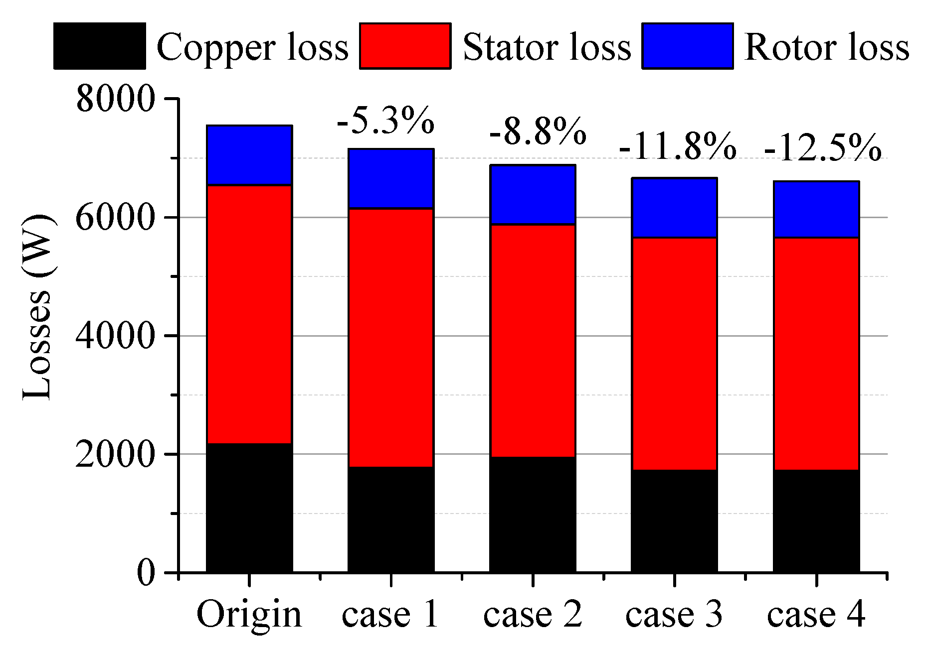
According to the above studies of the electromagnetic losses, the effects of the influencing factors (such as strand number of conductors, division of stator and employment of non-magnetic outer stator, material of pole fillers,) on the total loss were concluded in Figure 12. The stator was undivided, the strand number was 15, and al-alloy pole fillers were employed for the original prototype. The strand number was increased to 55 for the first case. The stator was divided and al-alloy was used as the outer stator for case 2. Case 3 was the sum of the above two methods. And the 2-mm s-steel stack pole fillers were adopted for case 4 on basis of case 3. Here, the stator loss includes the iron loss of the inner stator, the eddy-current losses of the outer stator and housing. The rotor loss includes eddy-current losses in the sleeve, magnets, fillers, and friction loss of the rotor [28]. It can be seen that the total loss could be decreased by 5.3% by only increasing the strand number of the conductors, 8.8% by only division of the stator and use of an al-alloy outer stator. By a combination of the two methods, the total loss would be decreased by 11.8%. And total loss can be further decreased by only 0.7% with the use of the 2-mm s-steel stack pole fillers, but it is meaningful for the rotor, due to the poor thermal conductivity of the carbon fiber sleeve.
3.5. Influences of Carrier Frequency of PWM Inverter on the Losses
Powered by the PWM inverter, lots of harmonic components of the current will be generated, which will result in an increase of the electromagnetic losses. With the carrier frequencies of 8, 12, 16 and 20 kHz, the copper loss, stator loss and rotor eddy-current loss of the optimized prototype, at rated load, were calculated in Figure 13, respectively. It can be seen that the total loss was increased largely by the PWM inverter, and the corresponding increasing percentages were 36.1%, 25.3%, 18.9% and 14.8%, compared with sinusoidal excitation. As the carrier frequency increases, the total loss was gradually close to that of the sinusoidal excitation. The copper loss and stator loss were a little different as the carrier frequency increased, but the variation of rotor eddy-current loss was very huge. As the carrier frequency increased from 8 kHz to 20 kHz, the total loss will have been decreased by 21.3%. Meanwhile, the reduction of rotor loss accounted for 17%, and the reductions of the copper loss and stator loss contributed 1.5% and 2.8%, respectively. Therefore, the rotor loss could be reduced largely by the increase of the carrier frequency, which was very helpful to reduce the temperature rise of the rotor, but its effects on copper and stator losses were not as high as the rotor loss.
4. Experiments
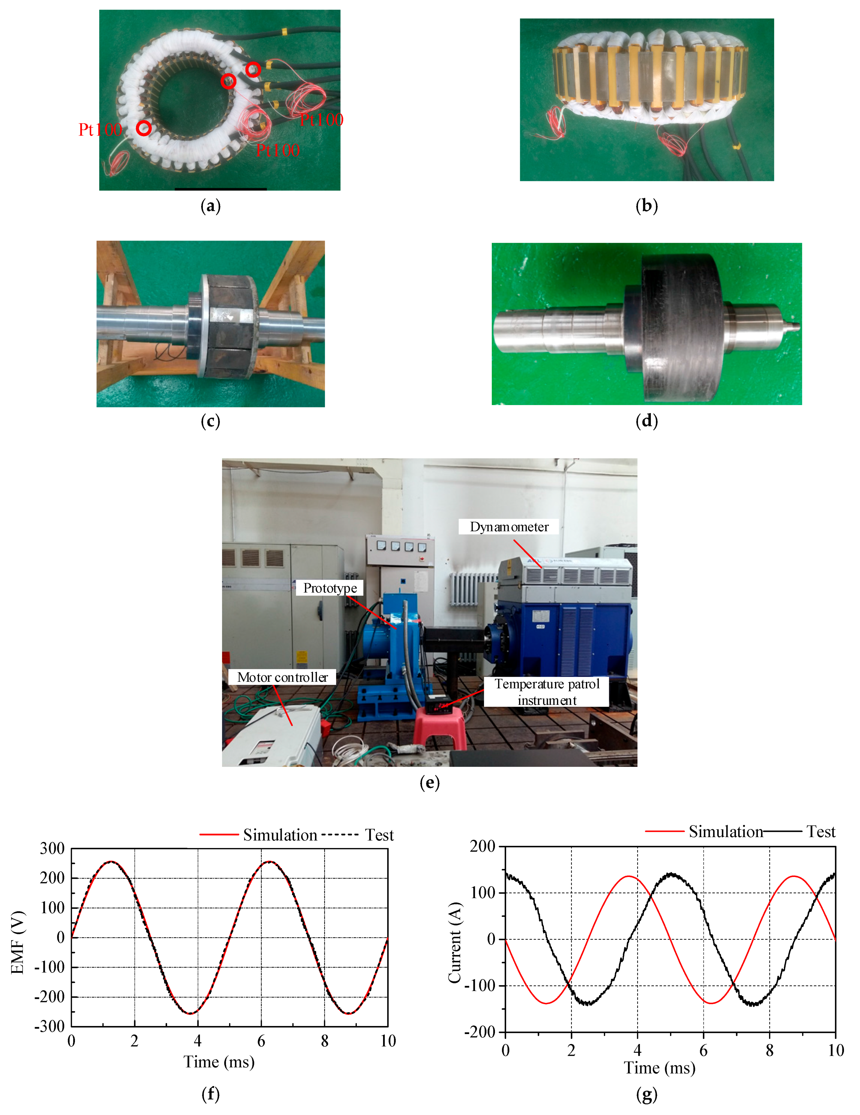
A 60 kW, 12,000 rpm small-scale prototype was manufactured based on the above studies. Toroidal windings were used, and the axial length of the ends of toroidal windings was made very short, as shown in Figure 14a,b. By calculation, the axial length of toroidal windings was reduced by 30.5% compared with double-layer lap windings. Carbon fiber retaining sleeve was mounted outside of the magnets shown in Figure 14c,d. A photograph of the complete experimental setup was shown in Figure 14e. The prototype was connected with dynamometer though a universal coupling. WT1800 power analyzer was used to record the test results.
The prototype was tested to 14,000 rpm with no load. Due to a limit put on the speed of the dynamometer, the prototype was only tested to 6000 rpm with load. The waveform of no-load back EMF of prototype driven by dynamometer at 6000 rpm was shown in Figure 14f. It agreed well with the simulation result. With the carrier frequency of 8 kHz of the inverter, the waveform of the rated current at 6000 rpm was tested, and shown in Figure 14g, and it also agreed well with the simulation result. So the electromagnetic performance of the prototype can be verified.
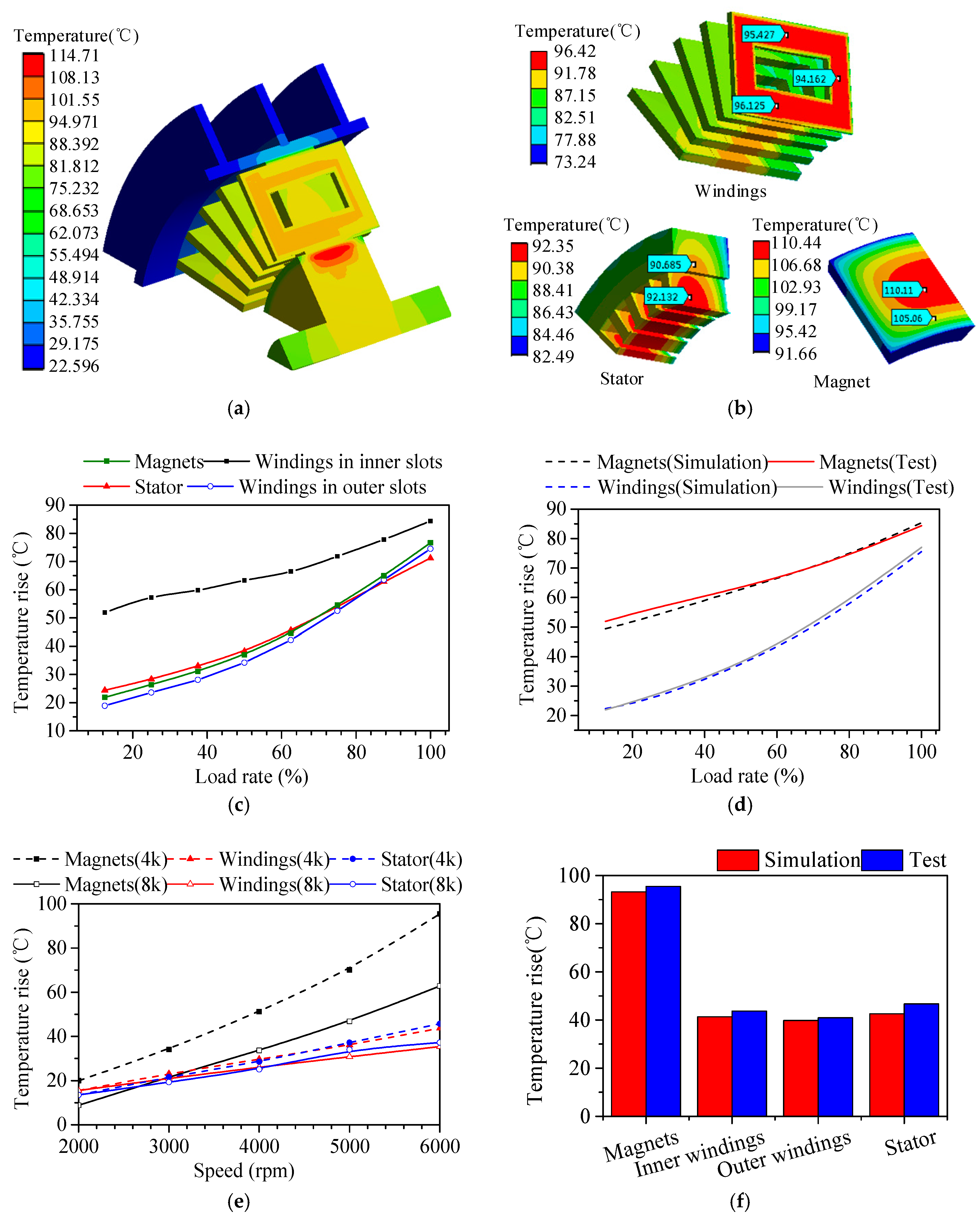
The losses of the small-scale prototype were analyzed on the basis of the above studies. Then loss densities of each part were calculated and mapped to the 3-d FEA model for thermal analysis. The convection-heat-transfer coefficients for the water jacket, airgap, surfaces of the internal end-space, such as end-windings, stator, sleeve and rotor core, were obtained by means of CFD method. The distribution of the temperature calculated by the FEA model were shown in Figure 15a,b, in which the prototype was operated at rated torque and 6000 rpm, powered by the inverter of 8 kHz, with the ambient temperature at 22 °C. As can be seen, the predicted maximum temperature was on the rotor. The temperature of the windings in the inner slot was about 1 °C higher than that in the outer slots. The highest temperature of the magnets was 110.44 °C.
To verify the losses and temperature rise, the test setup for the small-scale prototype was fabricated. The temperature rises of the stator and the windings in the inner slots and outer slots were tested by 3 pre-set Pt100 RTDs for the prototype, which were in the middle of one inner slot and one outer slot, as well as in the deep hole of the stator, respectively, shown in Figure 14a. But it was difficult to test the temperature rise of the rotor directly. It was finally predicted by the calculation of the temperature rise of the magnets, by means of the no-load back EMF tested, after the temperature was stable. The no-load EMF can be expressed as:
where, N is the number of turns in series in one phase, ϕδ0 is the airgap flux at no load. f, N, kdp, kϕ can be known for the prototype.
where, b′m0 and σ0 are the operating point of the magnets and magnetic leakage factor at no load, respectively, which also can be known for the prototype. Br is the remanence of PM material, Am is the cross-sectional area of the flux in one pole. By Equations (10) and (11), the no-load EMF could also expressed as:
Br is related with temperature and can expressed as:
where, αbr, IL are the coefficients of temperature and irreversible loss of PM materials. Br20 is the remanence of PM material at 20 °C. They can be known from the Manufacturer. t is the temperature of magnets. E0 is related with temperature due to Equations (12) and (13). Therefore, the temperature of the magnets can be predicted by means of the no-load EMF.
With the carrier frequency of 8 kHz of the inverter, the temperature rises of the prototype were tested at 6000 rpm with different load rates in Figure 15c. The highest temperature rise appeared at the magnets, and the temperature rise of the windings in the outer slots was a bit lower than that in the inner slots, which was in accordance with thermal analysis. As the load rate increased, the difference of the temperature rise between rotor and stator was smaller due to the increase of copper loss. The comparison between test and simulation of temperature rises of the magnets and windings in the inner slot was shown in Figure 15d. The test and simulation results showed good accordance, so the analysis of the losses for the toroidal-windings motor can be verified.
In order to clarify the influence of the carrier frequency on the rotor losses, the temperature rises of the prototype, under the carrier frequencies of 4 kHz and 8 kHz, were tested and compared at 50% load, respectively, shown in Figure 15e. As the speed increased, the temperature rise of the magnets was greatly influenced by the carrier frequency. The temperature rise of the magnets was decreased by 34.6%, compared the carrier frequency of 4 kHz with 8 kHz at 6000 rpm. The influences on the temperature rises of the windings and stator were not as high as on the magnets. According to the above studies, rotor loss was decreased by 39.7%, when the carrier frequency increases from 8 kHz to 16 kHz (the ratios of the carrier wave are also 20 and 40). With the same change of rotor loss, the rotor loss of the prototype at the speed of 6000 rpm under the carrier frequency of 4 kHz can be acquired, based on the known losses of carrier frequency of 8 kHz (the ratios of the carrier wave were also 20 and 40, respectively). Then the temperature rise were analyzed and compared with the test results in Figure 15f, which were in good agreement. So the influences of the carrier frequencies on the rotor losses can also be confirmed.
5. Conclusions
This paper provides the key design features of a flat-structure high-speed high-power PMSM for pulsed alternators. The toroidal-windings were used to reduce largely the axial length of the motor. The problem of leakage flux lines around the outer slots was solved by the division of stator and the use of non-magnetic material on the outer stator. Low-conductivity material of the retaining sleeve, the large airgap, the large number of segments of the magnets were together investigated to achieve the decrease in the axial length and improve the power density of a high-speed motor with flat structure. The electromagnetic design was verified by the test of a small-scale prototype.
The copper loss, iron loss and rotor loss of the toroidal-windings PMSM prototype were calculated, respectively, and the influencing factors on the losses were analyzed. The effects of the influencing factors on the total loss were then evaluated. By increasing the strand number of the conductors, the copper loss could be effectively reduced, and the total loss could be decreased by 5.3% for the prototype. By the division of the stator and the use of non-magnetic materials on the outer stator, the stator loss and copper loss could both be effectively reduced; thus, the total loss could be decreased by 8.8%. By the combination of these two methods, the total loss could be decreased by 11.8%. Replacing the aluminum alloy pole fillers with epoxy resin, the rotor loss could be decreased, and as a consequence, the total loss could be decreased by 0.7%, which is significant for the rotor. The employment of the 2-mm stainless steel stack or 1-mm aluminum alloy stack pole fillers will have had the same effect on the reduction of rotor loss as epoxy resin fillers, while maintaining the good thermal-conductivity properties of metal. The calculation of the losses was confirmed by tests of the temperature rise in the small-scale prototype.
Powered by the PWM inverter, the rotor was great influenced by the carrier frequency, whereas its influences on the losses of windings and stator were not as high as on the magnets. The employment of a high carrier frequency inverter was very helpful to decrease the rotor loss. The comparisons of the tested temperature rises in the small-scale prototype, between the carrier frequencies of 4 kHz with 8 kHz, showed the same results.
Author Contributions
Yuan Wan and Shumei Cui contributed equally to the research work described in this paper. Yuan Wan conducted the main work of design, simulation and experiments, while supervised by Shumei Cui. Shaopeng Wu reviewed and improved the paper by proofreading the paper for the correction of sentence structure and grammar. Liwei Song provided technical feedback and suggestions throughout the research.
Conflicts of Interest
The authors declare no conflict of interest.
References
- McNab, R. Large-Scale Pulsed Power Opportunities and Challenges. IEEE Trans. Plasma Sci. 2014, 42, 1118–1127. [Google Scholar] [CrossRef]
- Zhao, W.; Cheng, D.; Liu, Q.; Cui, S. Sensitivity Analysis and Regulation Strategy of Current Waveform for Two-Axis-Compensated Compulsators. IEEE Trans. Plasma Sci. 2013, 41, 1254–1259. [Google Scholar] [CrossRef]
- Wan, Y.; Cui, S.; Wu, S.; Song, L.; Milyaev, I.M.; Yuryevich, S.O. Shock-Resistance Rotor Design of A High-Speed PMSM for Integrated Pulsed Power System. IEEE Trans. Plasma Sci. 2017, 45, 1399–1405. [Google Scholar] [CrossRef]
- Gerada, D.; Mebarki, A.; Brown, N.L.; Gerada, C.; Cavagnino, A.; Boglietti, A. High-Speed Electrical Machines: Technologies, Trends, and Developments. IEEE Trans. Ind. Electron. 2014, 61, 2946–2959. [Google Scholar] [CrossRef]
- Binder, A.; Schneider, T.; Klohr, M. Fixation of buried and surface-mounted magnets in high-speed permanent-magnet synchronous machines. IEEE Trans. Ind. Appl. 2006, 42, 1031–1037. [Google Scholar] [CrossRef]
- Zhang, F.; Du, G.; Wang, T.; Wang, F.; Cao, W.; Kirtley, J.L. Electromagnetic Design and Loss Calculations of a 1.12-MW High-Speed Permanent-Magnet Motor for Compressor Applications. IEEE Trans. Energy Convers. 2016, 31, 132–140. [Google Scholar] [CrossRef]
- Ede, J.D.; Zhu, Z.Q.; Howe, D. Rotor resonances of high-speed permanent-magnet brushless machines. IEEE Trans. Ind. Appl. 2002, 38, 1542–1548. [Google Scholar] [CrossRef]
- Hong, D.K.; Woo, B.C.; Koo, D.H. Rotordynamics of 120000 r/min 15 kW Ultra high speed motor. IEEE Trans. Magn. 2009, 45, 2831–2834. [Google Scholar] [CrossRef]
- King, J.E.; Kobuck, R.M.; Repp, J.R. High speed water-cooled permanent magnet motor for pulse alternator-based pulse power systems. In Proceedings of the 2008 14th Symposium on Electromagnetic Launch Technology (EML), Victoria, BC, Canada, 10–13 June 2008; pp. 1–6. [Google Scholar]
- Spann, M.; Pratap, S.; Brinkman, W.; Perkins, D.; Thelen, R. A rapid fire, compulsator-driven railgun system. IEEE Trans. Magn. 1986, 22, 1753–1756. [Google Scholar] [CrossRef]
- Walls, W.A.; Spann, M.L.; Pratap, S.B.; Bresie, D.; Brinkman, W.; Kitzmiller, J.; Herbst, J.; Hsieh, K.; Liu, H.; Manifold, S.; et al. Design of a self-excited, air-core compulsator for a skid-mounted repetitive fire 9 MJ railgun system. IEEE Trans. Magn. 1989, 25, 574–579. [Google Scholar] [CrossRef]
- Atkinson, G.J.; Mecrow, B.C.; Jack, A.G.; Atkinson, D.J.; Sangha, P.; Benarous, M. The Analysis of Losses in High-Power Fault-Tolerant Machines for Aerospace Applications. IEEE Trans. Ind. Appl. 2006, 42, 1162–1170. [Google Scholar] [CrossRef]
- Li, W.; Qiu, H.; Zhang, X.; Cao, J.; Yi, R. Analyses on Electromagnetic and Temperature Fields of Superhigh-Speed Permanent-Magnet Generator with Different Sleeve Materials. IEEE Trans. Ind. Electron. 2014, 61, 3056–3063. [Google Scholar] [CrossRef]
- Reddy, P.B.; Zhu, Z.Q.; Han, S.H.; Jahns, T.M. Strand-level proximity losses in PM machines designed for high-speed operation. In Proceedings of the 2008 18th International Conference on Electrical Machines (ICEM), Vilamoura, Portugal, 6–9 September 2008; pp. 1–6. [Google Scholar]
- Iwasaki, S.; Deodhar, R.P.; Liu, Y.; Pride, A.Z.; Zhu, Q.; Bremner, J.J. Influence of PWM on the Proximity Loss in Permanent-Magnet Brushless AC Machines. IEEE Trans. Ind. Appl. 2009, 45, 1359–1367. [Google Scholar] [CrossRef]
- Thomas, A.S.; Zhu, Z.Q.; Jewell, G.W. Proximity Loss Study in High Speed Flux-Switching Permanent Magnet Machine. IEEE Trans. Magn. 2009, 45, 4748–4751. [Google Scholar] [CrossRef]
- Marcic, T.; Stumberger, B.; Stumberger, G.; Hadziselimovic, M.; Zagradisink, I. The impact of different stator and rotor slot number combinations on iron losses of a three-phase induction motor at no-load. J. Magn. Magn. Mater. 2008, 320, e891–e895. [Google Scholar] [CrossRef]
- Zhu, J.G.; Ramsden, V.S. Improved Formulations for Rotational Core Losses in Rotating Electrical Machines. IEEE Trans. Magn. 1998, 34, 2234–2242. [Google Scholar] [CrossRef]
- Stumberqer, B.; Hamler, A.; Gorican, V.; Jesenik, M. Accuracy of iron loss estimation in induction motors by using different iron loss models. J. Magn. Magn. Mater. 2004, 272, e1723–e1725. [Google Scholar] [CrossRef]
- Wan, Y.; Wu, S.; Cui, S. Choice of Pole Spacer Materials for a High-Speed PMSM Based on the Temperature Rise and Thermal Stress. IEEE Trans. IEEE Trans. Appl. Supercond. 2016, 26, 1–5. [Google Scholar] [CrossRef]
- Miyama, Y.; Hazeyama, M.; Hanioka, S.; Watanabe, N.; Daikoku, A.; Inoue, M. PWM Carrier Harmonic Iron Loss Reduction Technique of Permanent-Magnet Motors for Electric Vehicles. IEEE Trans. Ind. Appl. 2016, 52, 2865–2871. [Google Scholar] [CrossRef]
- Yon, J.M.; Mellor, P.H.; Wrobel, R.; Booker, J.D.; Burrow, S.G. Analysis of Semipermeable Containment Sleeve Technology for High-Speed Permanent Magnet Machines. IEEE Trans. Energy Convers. 2012, 27, 646–653. [Google Scholar] [CrossRef]
- Lazzari, M.; Miotto, A.; Tenconi, A.; Vaschetto, S. Analytical prediction of eddy current losses in retaining sleeves for surface mounted PM synchronous machines. In Proceedings of the 2010 XIX International Conference on Electrical Machines (ICEM), Rome, Italy, 6–8 September 2010; pp. 1–6. [Google Scholar] [CrossRef]
- Cho, H.W.; Jang, S.M.; Choi, S.K. A Design Approach to Reduce Rotor Losses in High-Speed Permanent Magnet Machine for Turbo-Compressor. IEEE Trans. Magn. 2006, 42, 3521–3523. [Google Scholar] [CrossRef]
- Li, W.; Qiu, H.; Zhang, X.; Cao, J.; Zhang, S.; Yi, R. Influence of Rotor-Sleeve Electromagnetic Characteristics on High-Speed Permanent-Magnet Generator. IEEE Trans. Ind. Electron. 2014, 61, 3030–3037. [Google Scholar] [CrossRef]
- Kawase, Y.; Tadashi, Y.; Tomohiro, U. Effects of carrier frequency of multilevel PWM inverter on electrical loss of interior permanent magnet motor. In Proceedings of the 2009 International Conference on Electrical Machines and Systems (ICEMS), Tokyo, Japan, 15–18 November 2009; pp. 1–15. [Google Scholar]
- Rezzoug, A.; Zaïm, M.E. High-Speed Electric Machines: Non-Conventional Electrical Machines; John Wiley and Sons: Eastbourne, UK, 2011; pp. 127–133. ISBN 978-1-84821-300-5. [Google Scholar]
- Saari, J. Thermal Analysis of High-Speed Induction Machines; Helsinki University of Technology: Helsinki, Finland, 1998; pp. 2–17. ISBN 951-22-5576-6. [Google Scholar]
Figure 1.
Configurations of, (a) double-layer lap windings; (b) toroidal windings; (c) concentrated windings; Characteristics of, (d) iron loss; (e) B-H of 35WW250 and B20AT1500.
Figure 1.
Configurations of, (a) double-layer lap windings; (b) toroidal windings; (c) concentrated windings; Characteristics of, (d) iron loss; (e) B-H of 35WW250 and B20AT1500.
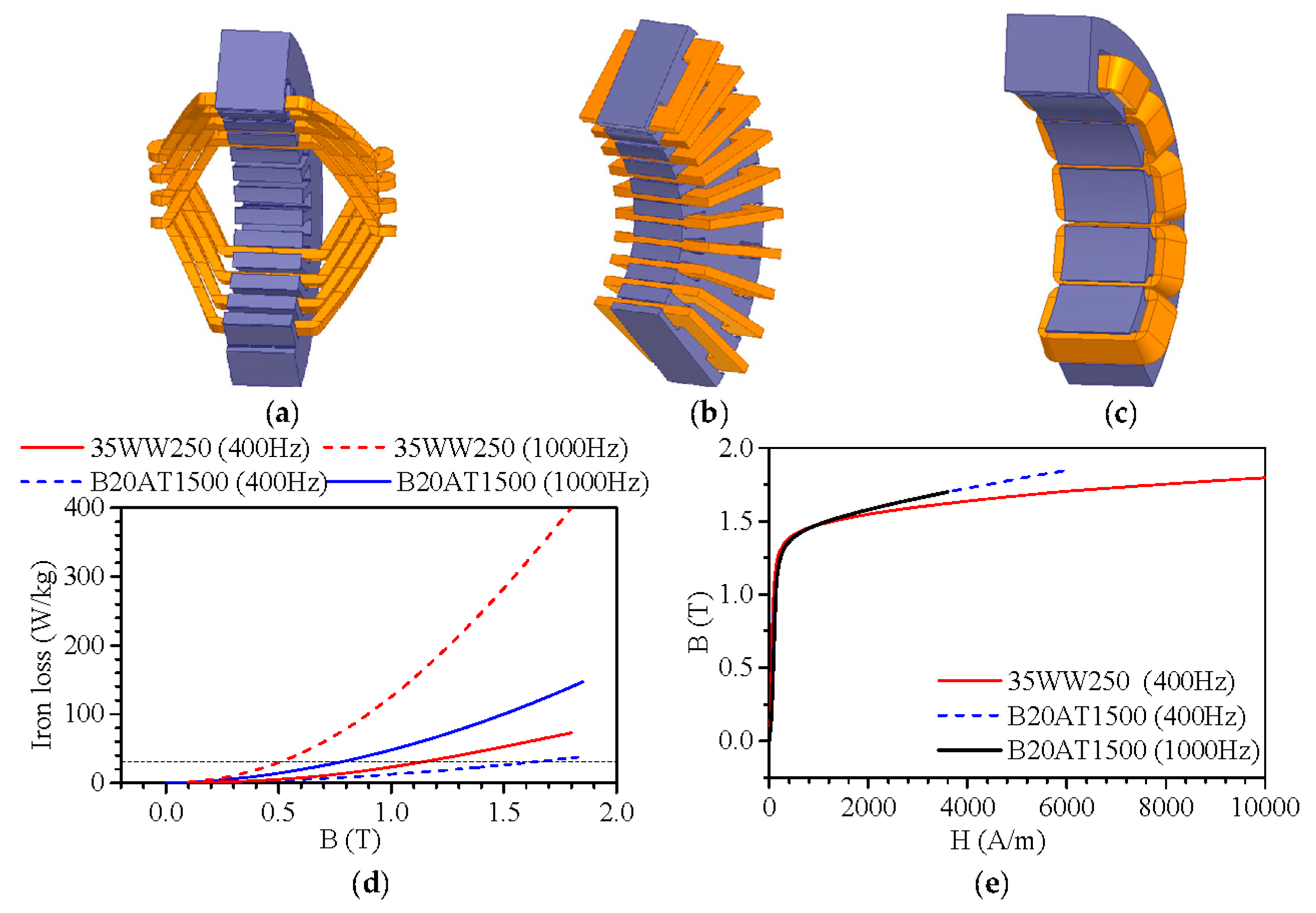
Figure 2.
FEA models of prototypes with the distribution of flux lines and densities of, (a) Case 1 (15,226 triangle elements, time step: 2.5 × 10⁻⁶ S); (b) Case 2 (26,136 triangle elements, time step: 2.5 × 10⁻⁶ S); (c) Case 3 (26,136 triangle elements, time step: 2.5 × 10⁻⁶ S); (d) Case 4 (15,107 triangle elements, time step: 5 × 10⁻⁷ S); (e) Calculated (FEM) iron loss; (f) radial flux densities in the middle of airgap; (g) harmonic spectrum of radial flux density; (h) rotor eddy-current loss.
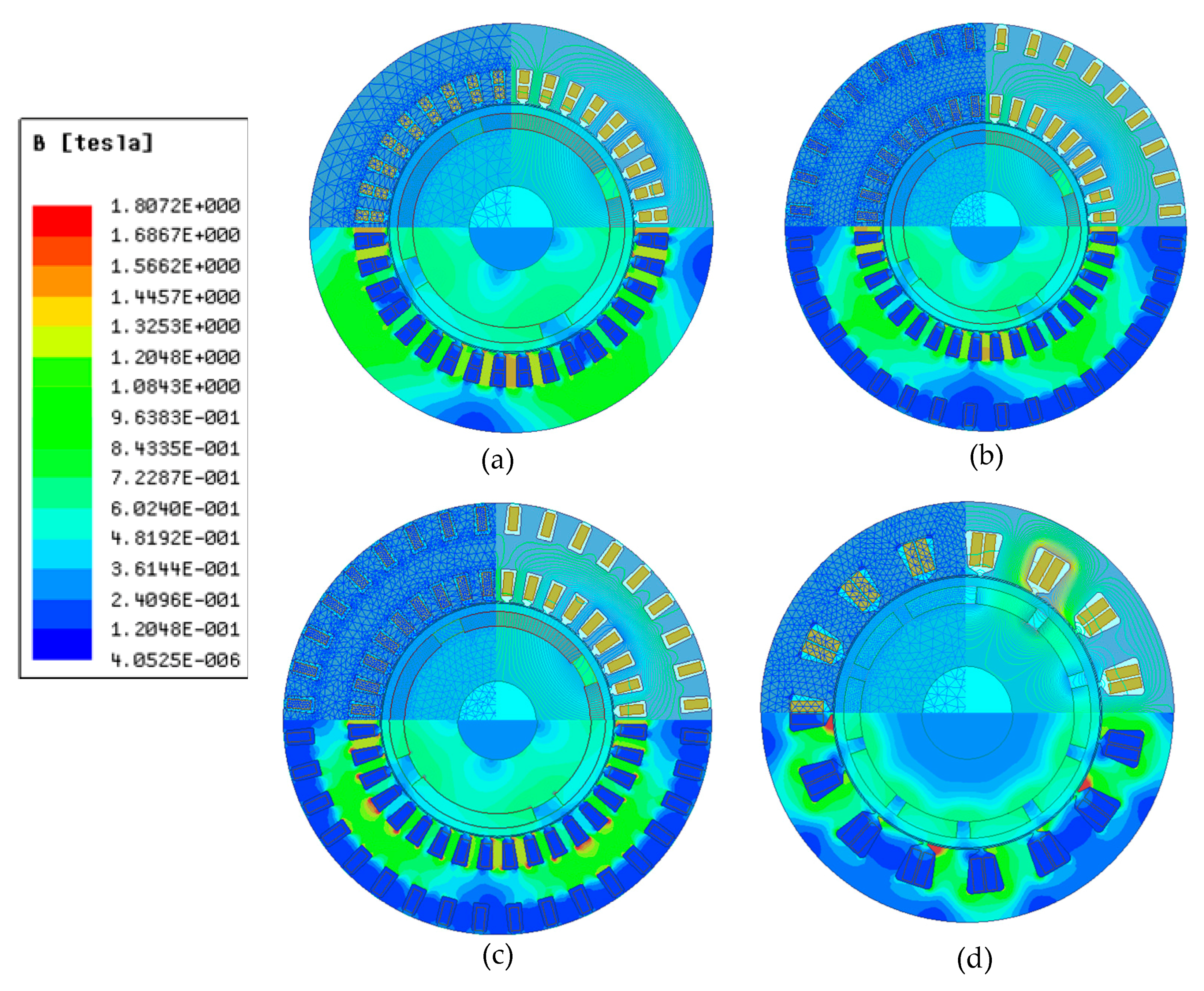

Figure 3.
(a) Distribution of flux lines of undivided stator with toroidal windings; (b) cross-section of divided stator and distribution of flux lines with outer stator of non-magnetic material.
Figure 3.
(a) Distribution of flux lines of undivided stator with toroidal windings; (b) cross-section of divided stator and distribution of flux lines with outer stator of non-magnetic material.
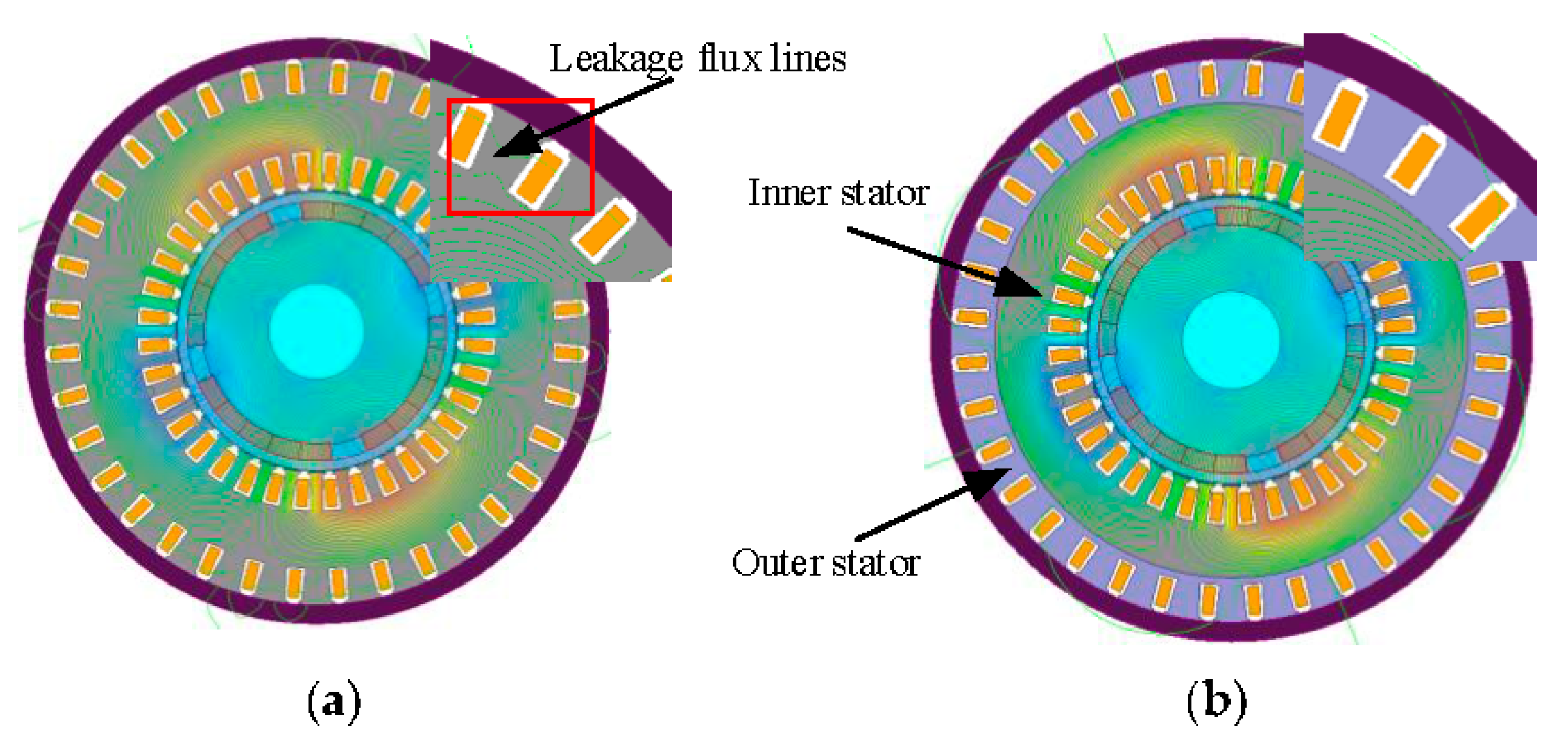
Figure 4.
Influences of conductivity of the sleeve materials on (a) sleeve loss; (b) magnet loss.

Figure 5.
Distribution of radial airgap flux densities at the surface of the rotor with different thickness of magnets (a) at no load; (b) at rated load; (c) harmonic spectrum of the radial airgap flux density at rated load; (d) eddy-current losses of retaining sleeve and magnets versus airgap length at rated load.
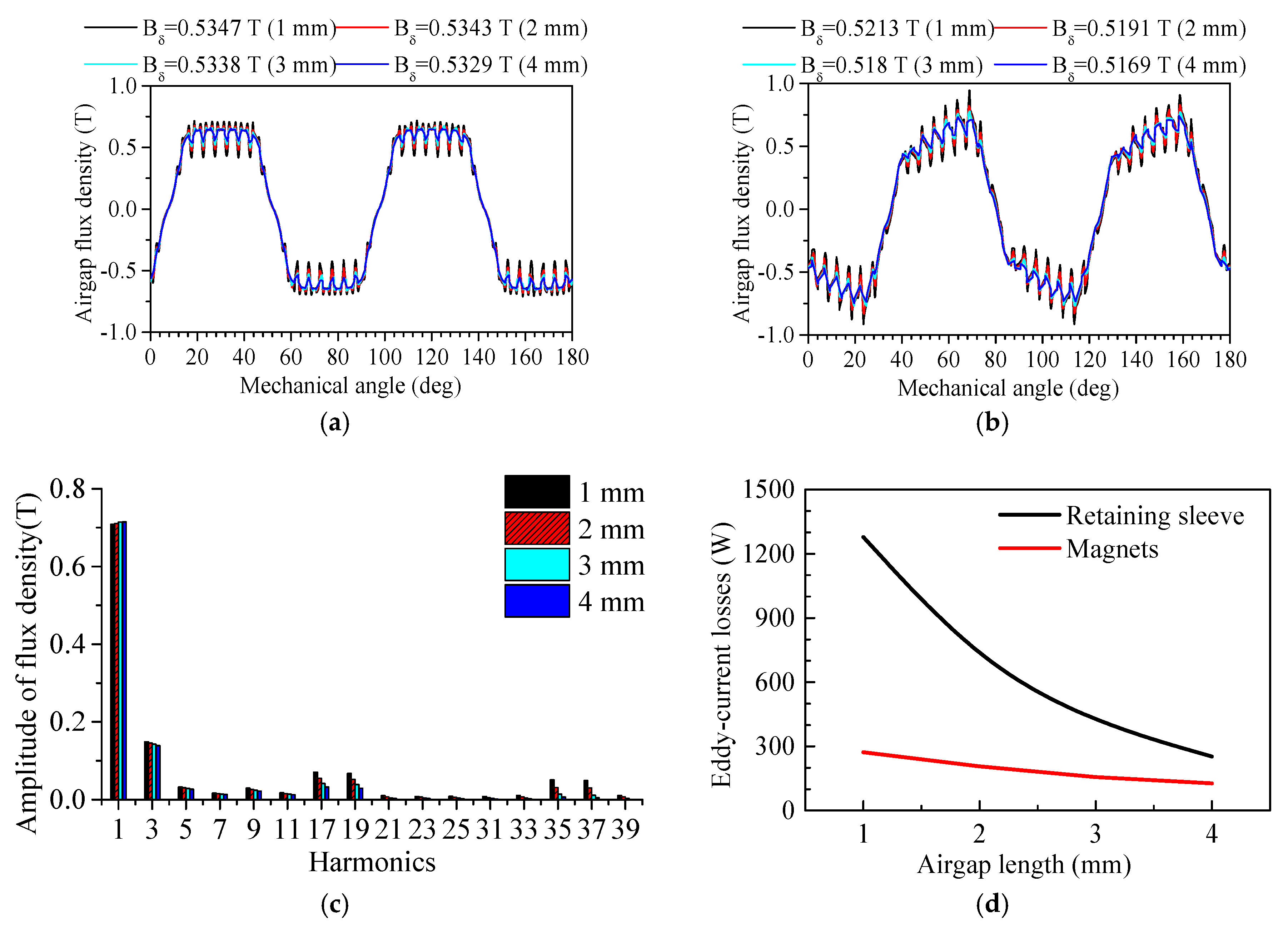
Figure 6.
(a) Eddy-current losses of magnets versus circumferential segmentation number; (b) eddy-current losses of magnets versus axial segmentation number.
Figure 6.
(a) Eddy-current losses of magnets versus circumferential segmentation number; (b) eddy-current losses of magnets versus axial segmentation number.

Figure 7.
(a) Configuration of the prototype; (b) waveform of the rated torque; (c) waveforms of no-load line back EMF; (d) waveforms of rated current.
Figure 7.
(a) Configuration of the prototype; (b) waveform of the rated torque; (c) waveforms of no-load line back EMF; (d) waveforms of rated current.
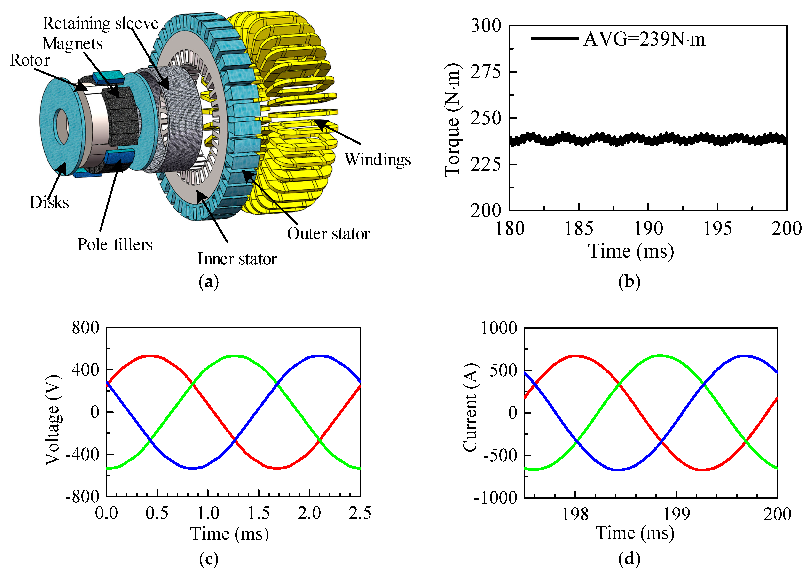
Figure 8.
(a) Coil segments for toroidal windings; FEA models and meshes the conductors of, (b) inner-slot winding; (c) outer-slot winding; (d) end winding.
Figure 8.
(a) Coil segments for toroidal windings; FEA models and meshes the conductors of, (b) inner-slot winding; (c) outer-slot winding; (d) end winding.

Figure 9.
Influences of the strand number of conductors on (a) inner-slot-windings loss; (b) end-windings loss; (c) total copper loss, under sine voltage and 8 k carrier-frequency PWM excitations, compared with DC loss as well.
Figure 9.
Influences of the strand number of conductors on (a) inner-slot-windings loss; (b) end-windings loss; (c) total copper loss, under sine voltage and 8 k carrier-frequency PWM excitations, compared with DC loss as well.

Figure 10.
(a) 3-d FE mesh model (360,409 tetrahedron element, time step: 5 × 10⁻⁶ S); (b) Distribution of eddy-current density in the shell and outer stator with outer stator material of al-alloy.
Figure 10.
(a) 3-d FE mesh model (360,409 tetrahedron element, time step: 5 × 10⁻⁶ S); (b) Distribution of eddy-current density in the shell and outer stator with outer stator material of al-alloy.
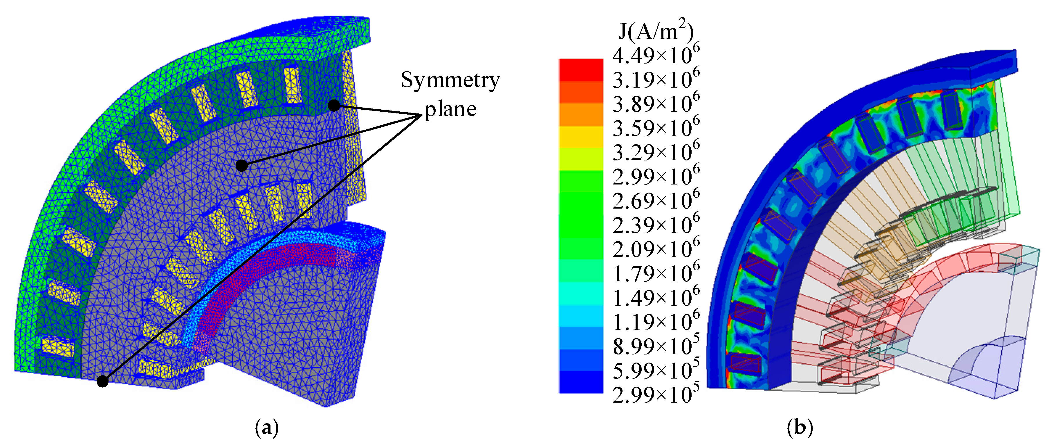
Figure 11.
Distributions of eddy-current density of (a) sleeve; (b) magnets; (c) pole filler; (d) configuration of the metal-stack pole filler; distributions of (e) eddy-current density; (f) eddy-current vectors in the metal-stack pole filler.
Figure 11.
Distributions of eddy-current density of (a) sleeve; (b) magnets; (c) pole filler; (d) configuration of the metal-stack pole filler; distributions of (e) eddy-current density; (f) eddy-current vectors in the metal-stack pole filler.

Figure 12.
Evaluation of influencing factors on the total loss.

Figure 13.
Influences of the carrier frequencies of the PWM inverter on the losses.
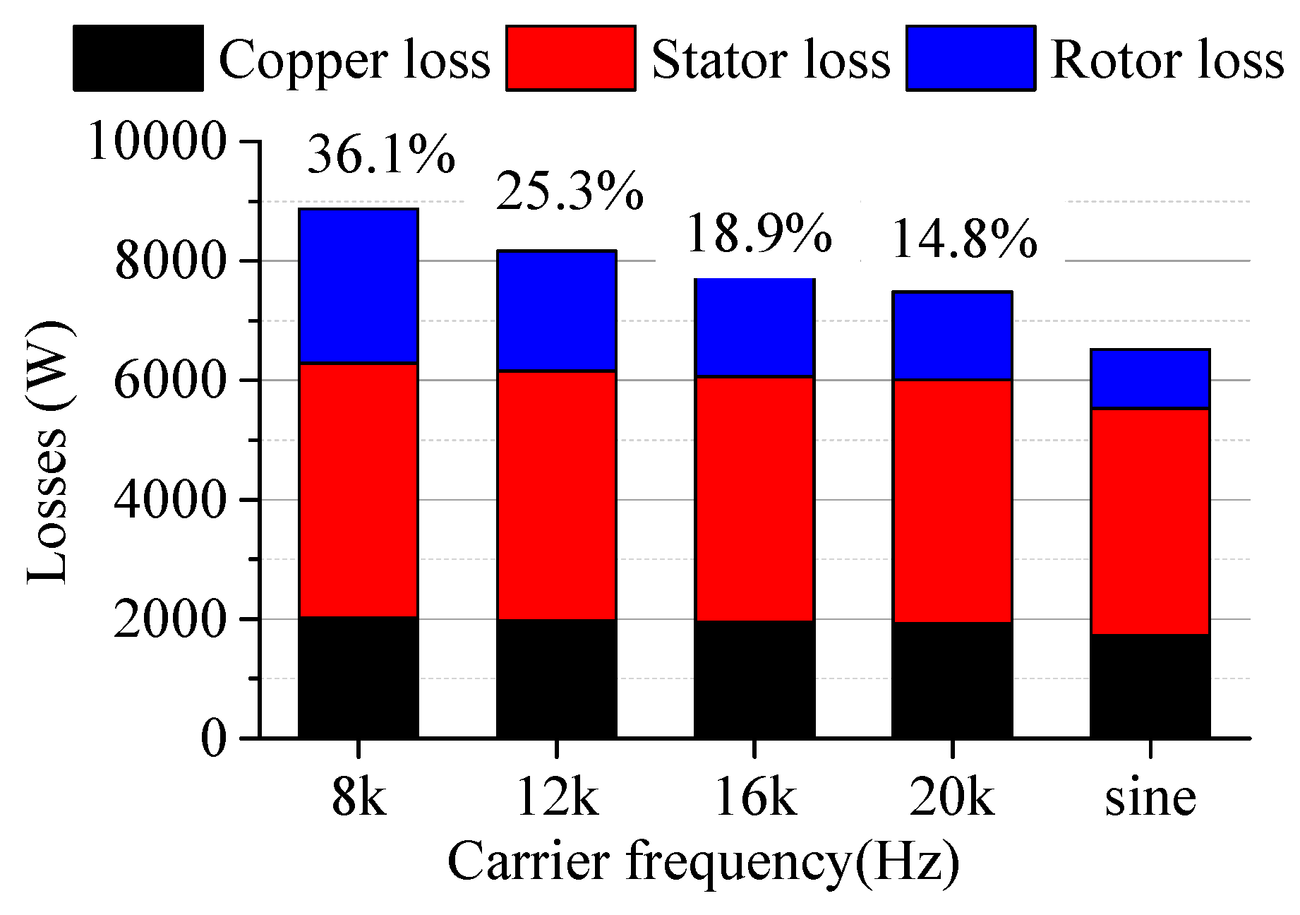
Figure 14.
Configurations of (a,b) stator of the prototype; (c) rotor with magnets mounted; (d) rotor after retaining sleeve mounted; (e) a photograph of the complete experimental setup; waveforms of (f) no-load back EMF; (g) rated current of prototype at 6000 rpm.
Figure 14.
Configurations of (a,b) stator of the prototype; (c) rotor with magnets mounted; (d) rotor after retaining sleeve mounted; (e) a photograph of the complete experimental setup; waveforms of (f) no-load back EMF; (g) rated current of prototype at 6000 rpm.

Figure 15.
Distribution of temperature rise of, (a) entire prototype; (b) different components of the prototype; (c) variation of the tested temperature rises with load rates at 6000 rpm; (d) comparison of the test and simulation temperature rises; (e) comparison of the tested temperature rises between the carrier frequencies of 4 kHz and 8 kHz; (f) comparison of the test and simulation temperature rises with carrier frequencies of 4 kHz.


Table 1.
Specifications of the four designs of the prototype.
| Cases | 1 | 2 | 3 | 4 |
|---|---|---|---|---|
| Poles number | 4 | 4 | 4 | 10 |
| Slot number | 36 | 36 | 36 | 15 |
| Rated Frequency (Hz) | 400 | 400 | 400 | 1000 |
| Winding type | Double-layer lap windings | Toroidal windings | Toroidal windings | Concentrated windings |
| Do of stator (mm) | 490 | 560 | 520 | 450 |
| Di of stator (mm) | 294 | 294 | 294 | 294 |
| Materials of stator | 35WW250 | 35WW250 | B20AT1500 | B20AT1500 |
| Effective length (mm) | 80 | 80 | 80 | 98 |
| Axial length (mm) | 290 | 180 | 180 | 180 |
| Heat loading (A2/m3) | 175.3 | 178.3 | 179.3 | 178.68 |
| EMF (V) | 216.4 | 220.1 | 220.8 | 220 |
| Rated power (kW) | 300 | 300 | 300 | 300 |
| Rated current (A) | 472.1 | 480.2 | 474.5 | 496 |
| Efficiency | 98.45% | 98.44% | 98.77% | 96.36% |
| Power factor | 0.9822 | 0.9672 | 0.9763 | 0.9554 |
| Power density (kW/kg) | 2.1914 | 1.8841 | 2.2605 | 2.5884 |
| Iron loss density (W/kg) | 30.59 | 29.14 | 26.88 | 30.14 |
Table 2.
Electromagnetic performance of the prototype with different airgap length.
| Cases | 1 | 2 | 3 | 4 |
|---|---|---|---|---|
| Airgap length (mm) | 1 | 2 | 3 | 4 |
| Magnet thickness (mm) | 16 | 18 | 20 | 22 |
| EMF (V) | 220.9 | 220 | 219.3 | 217.6 |
| Power (kW) | 300 | 300 | 300 | 300 |
| Rated current (A) | 477.4 | 475.2 | 474.2 | 475 |
| Torque ripple | 3.8 | 3.5 | 3.1 | 2.5 |
| Efficiency | 98.06% | 98.28% | 98.40% | 98.46% |
| Power factor | 0.9733 | 0.9753 | 0.9767 | 0.9741 |
| Loss density of magnets (W/m3) | 314.88 | 213.46 | 149.65 | 111.85 |
| Loss density of sleeve (W/m3) | 1803.68 | 976.03 | 582.53 | 364.77 |
| Intensity of PM utilization (kg/kW) | 0.022 | 0.0243 | 0.0266 | 0.0288 |
Table 3.
Specifications of the prototype.
| Parameters | Value | Parameters | Value |
|---|---|---|---|
| Poles number | 4 | Thickness of sleeve (mm) | 10 |
| Slots Number | 36 | Thickness of Magnet (mm) | 18 |
| Do of outer stator (mm) | 570 | Effective length (mm) | 80 |
| Di of outer stator (mm) | 490 | Material of inner stator | 35WW250 |
| Di of inner stator (mm) | 294 | Material of outer stator | Al-alloy |
| Airgap length (mm) | 2 | Material of retaining sleeve | Carbon fiber |
Table 4.
Copper loss with different materials of outer stator.
| Material of Outer Stator | Silicon Steel Sheet | Al-Alloy/Epoxy Glass Cloth Laminate |
|---|---|---|
| Inner-slot-wingdings loss (W) | 531.5 | 531.5 |
| Outer-slot-wingdings loss (W) | 531.5 | 305.1 |
| End-windings loss (W) | 1106 | 1106 |
| Total copper loss (W) | 2169 | 1942.6 |
Table 5.
Losses of stator with different materials of outer stator.
| Outer Stator Material | Silicon Steel Sheet | Al-Alloy | Epoxy Glass Cloth Laminate |
|---|---|---|---|
| Iron loss (W) | 1795 | 1901 | 1909 |
| Outer stator loss (W) | / | 1083 | 0 |
| Shell loss (W) | 2583 | 953 | 1366 |
| Total loss (W) | 4378 | 3937 | 3275 |
Table 6.
Eddy-current losses of rotor with different pole fillers.
| Material of Pole Fillers | Sleeve Loss (W) | Magnet Loss (W) | Filler Loss (W) | Total (W) |
|---|---|---|---|---|
| Al-alloy | 491.2 | 130.3 | 43.2 | 664.7 |
| Ti-alloy | 504.7 | 133.9 | 42.1 | 680.7 |
| S-steel | 500.3 | 128.6 | 58.1 | 687 |
| Epoxy resin | 504.7 | 126.2 | 0 | 630.9 |
| 2-mm s-steel stack | 499.3 | 128.5 | 0.64 | 628.4 |
| 1-mm al-alloy stack | 499.1 | 128.4 | 1.7 | 629.2 |
| 2-mm al-alloy stack | 498.6 | 128.6 | 7.6 | 634.8 |
© 2018 by the authors. Licensee MDPI, Basel, Switzerland. This article is an open access article distributed under the terms and conditions of the Creative Commons Attribution (CC BY) license (http://creativecommons.org/licenses/by/4.0/).
Share and Cite
MDPI and ACS Style
Wan, Y.; Cui, S.; Wu, S.; Song, L. Electromagnetic Design and Losses Analysis of a High-Speed Permanent Magnet Synchronous Motor with Toroidal Windings for Pulsed Alternator. Energies 2018, 11, 562. https://doi.org/10.3390/en11030562
AMA Style
Wan Y, Cui S, Wu S, Song L. Electromagnetic Design and Losses Analysis of a High-Speed Permanent Magnet Synchronous Motor with Toroidal Windings for Pulsed Alternator. Energies. 2018; 11(3):562. https://doi.org/10.3390/en11030562
Chicago/Turabian StyleWan, Yuan, Shumei Cui, Shaopeng Wu, and Liwei Song. 2018. "Electromagnetic Design and Losses Analysis of a High-Speed Permanent Magnet Synchronous Motor with Toroidal Windings for Pulsed Alternator" Energies 11, no. 3: 562. https://doi.org/10.3390/en11030562
Note that from the first issue of 2016, this journal uses article numbers instead of page numbers. See further details here.