Analysis and Design of a Maglev Permanent Magnet Synchronous Linear Motor to Reduce Additional Torque in dq Current Control


1
School of Electrical Engineering and Automation, Harbin Institute of Technology, Harbin 150001, China
2
School of Electrical Engineering, KAIST, Daejeon 34141, Korea
*
Author to whom correspondence should be addressed.
Energies 2018, 11(3), 556; https://doi.org/10.3390/en11030556
Submission received: 21 January 2018
/
Revised: 7 February 2018
/
Accepted: 28 February 2018
/
Published: 5 March 2018
(This article belongs to the Section I: Energy Fundamentals and Conversion)
Abstract
:The maglev linear motor has three degrees of motion freedom, which are respectively realized by the thrust force in the x-axis, the levitation force in the z-axis and the torque around the y-axis. Both the thrust force and levitation force can be seen as the sum of the forces on the three windings. The resultant thrust force and resultant levitation force are independently controlled by d-axis current and q-axis current respectively. Thus, the commonly used dq transformation control strategy is suitable for realizing the control of the resultant force, either thrust force and levitation force. However, the forces on the three windings also generate additional torque because they do not pass the mover mass center. To realize the maglev system high-precision control, a maglev linear motor with a new structure is proposed in this paper to decrease this torque. First, the electromagnetic model of the motor can be deduced through the Lorenz force formula. Second, the analytic method and finite element method are used to explore the reason of this additional torque and what factors affect its change trend. Furthermore, a maglev linear motor with a new structure is proposed, with two sets of 90 degrees shifted winding designed on the mover. Under such a structure, the mover position dependent periodic part of the additional torque can be offset. Finally, the theoretical analysis is validated by the simulation result that the additionally generated rotating torque can be offset with little fluctuation in the proposed new-structure maglev linear motor. Moreover, the control system is built in MATLAB/Simulink, which shows that it has small thrust ripple and high-precision performance.
1. Introduction
Linear motors are now an increasingly popular alternative solution for linear positioning applications [1,2,3,4]. In general, the linear motor-based positioning systems feature higher performance in terms of accuracy, thrust and acceleration compared with rotating motor based systems [5]. Three common support methods are available for the linear movement, namely mechanical method [6,7,8], air floatation method [9,10,11] and magnetic levitation method [12,13,14,15]. The mechanical method has the advantage of low cost and has been widely used in simple linear movement applications. However, the friction force is inevitable, which limits the control accuracy. The air flotation method has no physical contact and thus has no friction force as the mechanical method. The disadvantage of this method is that the high-pressure air causes high-frequency vibration. Moreover, this method is subject to disturbance vulnerability and low stiffness. Some ultra-precision equipment needs to work in the vacuum state, which further limits the application of the air flotation method. The maglev permanent magnet synchronous linear motor has the advantages of no mechanical friction and high stiffness and being suitable for working in a vacuum state. Thus, it has been researched by many scholars for wide applications in high-speed, large-acceleration and high-precision linear positioning movement [16,17,18].
The maglev linear motor has three degrees-of-freedom (DOF). They are realized by the thrust force in the x-axis, the maglev force in the z-axis and the torque around the y-axis respectively. The commonly adopted traditional linear motor control method is based on dq decoupling, which can realize the decoupling control of the thrust and levitation force through the respective iq and id. With the dq transformation, ABC three-phase currents can be obtained from the needed iq and id. The three phase currents under the magnetic field can generate respective position dependent force on the three winding. Both the thrust force and levitation force can be seen as the sum of the forces on the three windings. The resultant thrust force and resultant levitation force are independently controlled by iq current and id current respectively. Thus, the commonly used dq transformation control strategy is suitable for realizing the control of the resultant force, either thrust force and levitation force. However, the forces on the three windings also generate additional torque. For the levitation force, they act on the three different points and thus generate that torque. For the thrust force in the direction of x-axis, that torque still exists because it does not go in line with the center the mover mass, it can also generate torque which is not dependent on the mover position.
The traditional linear motor adopting the linear guide and sliding module has only single DOF, thus the imposed torque has little influence on the system due to the mechanical constraint. However, the imposed torque will change the gap of the maglev linear motor at the two ends due to the lack of mechanical constraint. The gap change can make it extremely difficult to realize the proper control of the electromagnetic force. Therefore, how to decrease the imposed torque is the key factor to realize the precise control of the maglev linear motor. The three forces on the three-phase windings are the function of the position in the magnetic field.
To decrease the disturbance torque paper [19] has proposed to use two permanent magnet arrays which are placed opposite to each other. When two movers are mounted back-to-back and moved in between the permanent magnet arrays, the torques produced by the movers cancel each other out. This arrangement, however, cannot be used to preload aerostatic bearings or in single side magnetic levitation. A commutation and switching algorithm for multi DOF moving magnet actuators with permanent magnets and integrated active magnetic bearing has been proposed in [20]. Wrench current decoupling method has been applied in the multi DOF control of the linear motor. However, this method requires a full-bridge drive unit to drive one winding, which increases the hardware cost and complexity. Paper [21] has proposed three DOF control strategy for an iron core linear permanent magnet motor, which is based on the dq decomposition. To realize the three DOF control, however, the conventional dq control strategy cannot realize the desired performance and thus more complex decoupling control algorithm needs to be designed.
To decrease the disturbance torque caused by the conventional dq control strategy, this paper proposed a new structure of maglev linear motor. The mover has two sets of three-phase windings which are arranged with a phase difference of 90 electrical degrees. When the sets of windings have an initial phase difference of 90 electrical degrees, the disturbance torques in the two sets of windings are in the opposite direction, which can cancel each other out. Traditional dq control strategy can be used to realize the three DOF control without complex decoupling and compensation. Therefore, the traditional drive consisting of three half-bridges can be used to the proposed new-structure maglev linear motor. The proposed new-structure maglev linear motor features advantages such as additional torque offset, simple control strategy and simple hardware requirement.
The structure of the paper is as follows. In Section 2, the three DOF electromagnetic model of ironless maglev permanent magnet synchronous linear motor is introduced. It includes the coordinate system definition of maglev system, the analytic formula of Halbach magnetic field and the analytic formula of the electromagnetic force and torque. In Section 3, the disturbance torque around the center of the mover mass caused in the conventional dq decoupling strategy is explored. In Section 4, the new-structure linear motor is proposed to offset the disturbance torque; moreover, the motor structure is optimally designed. In Section 5, the simulation has been done to validate the disturbance torque offset and the effectiveness of the dq decoupling strategy in the control system. Section 6 presents a simple conclusion of this paper.
2. Maglev Permanent Magnet Linear Motor Electromagnetic Model
2.1. Coordinate Definition
Figure 1 show the model of a maglev linear motor which consists of the stator, air gap and the mover. The stator is made of ABC three-phase windings and backplane. The three-phase windings are arranged in the direction of x. The three-phase winding arrangement width is 4τ (τ is the pole pitch). The stator is made of magnetic conductive plate and permanent magnets. The permanent magnets are arranged in the form of Halbach.
Two coordinate systems are defined in Figure 1. The first one is the stator coordinate system denoted by the superscript s, which is shown as:
The other one is the mover coordinate system denoted by the superscript m. It can be expressed as:
The vector p is the position vector that is defined as pointing from the stator coordinate system to the mover coordinate system. It can be expressed as:
The two coordinate systems can be converted into each other with the coordinate transformation through the following equations [22]:
The orientation transformation matrix is defined as:
where ϕ, θ and φ are the rotation angles about the sx-, sy-, and sz-axes, respectively.
2.2. Magnetic Field Analysis
The literature review shows that the magnetic field of the Halbach permanent magnet array is predicted by either the harmonic model [23] or the transfer relationship [24], which can be eventually solved as boundary-value problems using the Maxwell equation and the scalar potential. The magnetic field analysis of the linear motor can be done under several hypotheses, such as the neglection of the end effects and the magnetic field saturation, etc. [22,25]. In Figure 1, the magnetic flux density B can be decomposed in the x and z directions as follows [26]:
where μ0 and M0 denote the permeability of the free space and the peak magnetization magnitude of permanent magnets, respectively. hm represents height of a single permanent magnet.
To make the above equations more concise, we assume that
Based on the above assumption, Equations (11) and (12) can be rewritten as:
The above equations can be transformed into those in the mover coordinate system which are shown as:
2.3. Electromagnetic Force and Torque Analysis
There are three common analytical ways to solve magnetic force in his research report, namely virtual work method, Maxwell stress method, and the Lorentz force equation method [27]. Among them, Lorentz force equation method is the most straightforward and simple one, which is shown as [28,29]:
where B is the magnetic flux density of the magnet array, J is the volume current density in the coil, V is the volume of the coil, r is the vector from the point about which the torque is calculated.
The volume current density is dependent on the current, which is shown as:
where N is the turns of the winding, wc and hc are the winding width and height respectively as shown in Figure 2.
In the mover local coordinate system, the electromagnetic force and torque on the straight segment of the coil can be derived as:
According to the model in Figure 2, The model simplification method is paper [23] is used to simplify the winding into 2 filaments with current i replacing current density J, thus the electromagnetic force and torque in the j-th winding (when lcw = τ) can be expressed as:
According to the calculation results, the electromagnetic force and torque can be derived as:
where, rz is the equivalent force arm in the mz-direction from the coil to the mover mass center. Kz can be expressed as:
3. Additional Torque Analysis and Offset
3.1. dq Coordinate Transformation
The control of the three-phase AC motor can be seen as that of DC motor through the coordinate transformation. The three-phase currents can be transformed into force current iq and magnetic field excitation current id. Thus, the thrust force and the levitation force of linear motor can be independently controlled by the current iq and id respectively.
The current transformation from the dq coordinate to the ABC coordinate system is shown as:
Through Equation (29), it can be known that the needed three-phase currents can be calculated from the desired id and iq.
3.2. Torque Analysis
Once the coil is fixed on the mover, the relative position between the windings becomes a known constant, and the force and torque on the mass center of the mover can be calculated by substituting the coordinates of each coil into Equations (25)–(27) separately and then add them up.
The electromagnetic force generated by three-phase winding is expressed as:
Substituting the current in Equation (29) and the position of the coil in the mover coordinate system into Equation (30), we can get
Through mathematical analysis it can be known that
Thus, Equation (31) can be rewritten as:
In a similar way, we can get
The torque of the three-phase winding on the center of mass is
Substituting the current in Equation (29) into Equation (35), we can get
It can be seen from Equations (33) and (34) that the required Fx and Fz forces can be obtained from the given currents iq and id. From Equation (36) it can be seen that both the d-axis current and the q-axis current can produce a torque which varies with the position, and the thrust force Fx generated by the q-axis current can generate a constant torque related to the arm rz.
3.3. Finite Element Analysis of AdditionalTorque
The finite element simulation software is used to model and simulate the motor structure in Figure 1 with the main parameters shown in Table 1. In the simulation, two groups of excitation, id = 3.7 A, iq = 0 A and id = 0 A, iq = 3.7 A, are applied respectively. The simulation results are shown in Figure 3. When id = 3.7 A, iq = 0 A, the torque Td (blue curve in Figure 3) to the centroid of the mover changes from −0.33 N·m to 0.33 N·m, and the period is τ. When id = 0 A, iq = 3.7 A, the torque Tq (red curve in Figure 3) to the center of the mover varies from −0.22 N·m to 0.42 N·m, and the period is also τ, but a constant offset is generated. This offset results from the thrust Fx in Equation (36).
4. Optimal and Design of Motor Structure
4.1. Structure Design
In order to keep the thrust force and levitation force constant at a magnetic field-free position, the force generated by each of the coils varies at different relative magnetic field positions, thus giving rise to a torque relative to the centroid of the mover. According to the torque fluctuations with respect to positions caused by current id and iq, the use of two motor units is proposed to generate the opposite torque ripple to cancel each other out to achieve optimal additional torque. Electromagnetic force is generated by the current and the magnetic field together, and the current and magnetic field varies nearly sinusoidal (cosine) and their period is both twice the pole pitch τ. From Equation (36), it can be known that the period of torque is a pole pitch τ. Figure 3 also shows that the undulating period of the additional torque is a pole pitch τ. Therefore, it is necessary to maintain the relative phase difference 1/2τ of the two motor units to achieve the offset of the additional torque ripple.
Figure 4 shows the designed three DOF maglev linear motor, which is mainly composed of the mover and stator. The mover adopts ironless structure and consists of two sets of ABC three-phase winding and the backplane. The stator is composed of with a uniformly arranged Halbach permanent magnet and a yoke plate made from magnetic material. The arrangement of the two sets of windings is as follows. The mover is divided into two parts by its mass center in the thrust x direction, and each part is equipped with a set of three-phase windings to form a complete three-phase motor unit, with the corresponding phase difference between the initial phase of the winding being 4.5τ, as shown in Figure 5.
4.2. Optimization of Halbach Permanent Magnet Array
The size of the main permanent magnet and the auxiliary permanent magnet can affect the distribution of the magnetic induction intensity in the air gap, thus the structure optimization of the permanent magnet is necessary for the desired performance. When the pole pitch is fixed, the variable structure dimensions wm1, wm2, hm of permanent magnet array, which affect the distribution of the magnetic induction intensity in the air gap, are shown in Figure 6.
The wm1, wm2 and hm in Figure 6 are set as variables to optimize the force coefficient k of the linear motor. The width of the main permanent magnet wm1 is in the range of 1–14 mm, the width of the auxiliary permanent magnet wm2 is in the range of 14–1 mm, and the thickness of the permanent magnet hm is in the range of 1–25 mm. Besides, the relation of wm1 + wm2 = τ should be satisfied. The finite element simulation software is used and the force coefficient k of different sizes of structures with in different variable values is calculated. The simulation results are shown in Figure 7.
It can be seen from Figure 7 that the main permanent magnet width wm1 and the auxiliary permanent magnet width wm2 have influence on the force coefficient k. The force coefficient is small in the initial stage during the change of wm1. The force coefficient keeps increasing with the increase of wm1 until a certain critical point. After this critical point, the force coefficient begins to decrease when wm1 continues to increase. In Figure 7, the maximum value of force coefficient k appears when wm1 is in the range of 8–9 mm, so the simulation is further carried out in the interval of 8–9 mm with steps of 0.1 mm. The optimal force coefficient is achieved when the width of the permanent magnet is wm1 = 8.7 mm and wm2 = 6.3 mm. The relationship between the force coefficient k and the height of the permanent magnet hm with the above optimized width of the permanent magnet is shown in Figure 8.
It can be seen from Figure 8 that the influence permanent magnet thickness on the force coefficient k and can be roughly divided into three ranges. In the range of 1–10 mm for the permanent magnet thickness, the change of force coefficient k increases almost linearly with the increase of the permanent magnet thickness. In the range of 1–25 mm, the force coefficient increases slowly with the increase of the thickness of the permanent magnet. When the thickness is larger than 20 mm, and the force coefficient is nearly constant with the increase of the thickness of the permanent magnet. The selection of the thickness of the permanent magnet should depend on the type of motor and specific requirements. As the motor is moving-coil type maglev permanent magnet synchronous linear motor, the stator mass does not affect the ratio of the thrust to the moving parts, the thickness of the permanent magnet is selected as 20 mm.
4.3. Optimization of Coil Thickness
After the optimization of the permanent magnet size, the thickness of the coil in the z-direction is selected from 1–20 mm, and the simulation result is shown in Figure 9.
Figure 9 shows the relationship between a motor unit thrust coefficient and the thickness of the coil. It is seen from Figure 9 that in the initial stage, the force coefficient k increases significantly with the increase of the coil thickness. When the coil thickness is beyond 12 mm, the increase of the coil thickness has little influence on the coil thrust output, which is caused by the attenuation of the magnetic field, thus the coil thickness hc is selected to be 12 mm.
5. Simulation Result and Analysis
The proposed motor structure has been explored using finite element simulation software. In the simulation, the open-loop current is given to the motor based on the relative position between the magnetic field and the motor mover to validate the offset of the additional torques. Moreover, MATLAB/Simulink has been used to build the motor control system to explore its control accuracy in the three DOF and its robustness.
5.1. Finite Element Simulation
The proposed maglev linear motor is simulated in the finite element software based on the motor parameters given in Table 2.
The amplitude of three phases current is 2 A. The motor mover can move in the range of 0–6τ (0–90 mm). The simulation result is shown in Figure 10 and Figure 11.
Figure 10 shows the electromagnetic torques of the two winding units. The blue line represents the electromagnetic torque of winding unit I while the red line represents that for winding unit II. It can be seen from Figure 10 that the electromagnetic torque is dependent on the mover position in x-axis, moreover they are in opposite directions. Figure 11 shows the simulation results of the proposed new-structure maglev linear motor with d-axis and q-axis currents fed. It can be seen from Figure 11a that the thrust force and levitation force generated by linear motor are the sum of two winding units. Fx and Fz are kept constant when q-axis and d-axis currents are kept constant. Figure 11b shows that the mover position dependent periodic part of the additional torque has been offset with a constant part left and it fluctuates around 0.455 N·m. The torque of 0.455 N·m reflects the last part in Equation (36). This constant part is because the thrust force Fx does not go in line with the center of the mass. Its height can be affected by the mover load shape and its mass. Nevertheless, it can be further offset by adjusting the levitation forces in the two sets of winding units, which is explored in next section.
5.2. Position Closed Loop Verification
The control system is shown in Figure 12. xr, zr and θr are the given references in the three DOF. They are compared with the practical values, after which the proportional-integral-derivative (PID) controller is used to regulate the needed force. Currents id1, id2, iq1 and iq2 are then calculated from the regulated signals through the force distribution unit. The dq currents can be then further transformed into three-phase currents through the coordinate transformation. Finally, the real three-phase currents can be given to the maglev linear motor through the current source inverter. The controller parameters are shown in Table 3.
The forces and torque in the three DOF are shown as:
where, L is the equivalent force arm between the winding unit and the mover center of mass.
The control system for the proposed maglev linear motor is built in MATLAB/Simulink. The simulation time is set to be 0.2 s. At 0 s, the given reference in z-direction is 1 mm and at 0.05 s the given reference in x-direction step rises to 0.1 m. The rotation angle θ is kept to be 0. The simulation result is shown in Figure 13.
It has been seen from Figure 13a that the control system for the proposed maglev linear motor based on dq decoupling strategy has good positioning accuracy in the three DOF. When the linear motor moves in the direction of x-axis, the rotation angle θ fluctuates between −2.89 μrad and 2.63 μrad with a very small torque change. 300 N is the largest thrust that can be generated by the motor. The simulation result shows that the mover position dependent periodic part can be offset with the two sets of winding units, moreover the constant part, not dependent on the mover position, can be further offset by adjusting the levitation forces in the two sets of winding units through position close-loop control.
6. Conclusions
This paper has proposed a new-structure maglev linear motor that has thee DOF. The main innovation of this motor is to offset the mover position dependent periodic part of the additional torque caused in the typical dq decoupling control method through designing two winding units with the relative phase difference that can make the torques caused by d-axis current and q-axis current have the opposite direction and thus can offset each other. The conventional dq decoupling control strategy and three-phase motor driver can be used for the control system adopting this new-structure maglev linear motor. The finite element simulation has been done to prove that the proposed motor can offset the mover position dependent periodic part of additional. Moreover, the control system is designed to control it with the conventional dq decoupling control strategy. It has been found that the constant part, not dependent on the mover position, can be further offset by adjusting the levitation forces in the two sets of winding units through position close-loop control. The thrust and torque ripples are very small, which guarantees high positioning precision.
Acknowledgments
This work was supported in part by the State Key Program of National Natural Science of China under Grant (51537002), in part by the National Natural Science Foundation of China (51607044), in part by the China Postdoctoral Science Foundation Funded Project (2015M80262), in part by “the Fundamental Research Funds for the Central Universities” (Grant No. HIT. NSRIF. 2017010), and in part by the National Science and Technology Major Project (2009ZX02207-001).
Author Contributions
Design of the research scheme and research supervision: Feng Xing, Baoquan Kou and Tiecheng Wang. Performing of the research and writing of the manuscript: Lu Zhang, Chaoning Zhang.
Conflicts of Interest
The authors declare no conflict of interest.
References
- Tutelea, L.N.; Kim, M.C.; Topor, M.; Lee, J.; Boldea, I. Linear Permanent Magnet Oscillatory Machine: Comprehensive Modeling for Transients with Validation by Experiments. IEEE Trans. Ind. Electron. 2008, 55, 492–500. [Google Scholar] [CrossRef]
- Abdollahi1, S.E.; Mirzayee, M.; Mirsalim, M. Design and Analysis of a Double-Sided Linear Induction Motor for Transportation. IEEE Trans. Magn. 2015, 51, 8106307. [Google Scholar] [CrossRef]
- Boldea, I.; Tutelea, L.N.; Parsa, L.; Dorrell, D. Automotive Electric Propulsion Systems with Reduced or No Permanent Magnets: An Overview. IEEE Trans. Ind. Electron. 2014, 61, 5696–5711. [Google Scholar] [CrossRef]
- Lu, L.; Chen, Z.; Yao, B.; Wang, Q.F. A Two-Loop Performance-Oriented Tip-Tracking Control of a Linear-Motor-Driven Flexible Beam System with Experiments. IEEE Trans. Ind. Electron. 2013, 60, 1011–1022. [Google Scholar] [CrossRef]
- Profumo, F.; Tenconi, A.; Gianolio, G. Design and Realization of a PM Linear Synchronous Motor with a Very High Thrust/Normal Force Ratio. In Proceedings of the 2001 IEEE Industry Applications Conference (36th IAS Annual Meeting), Chicago, IL, USA, 30 September–4 October 2001; pp. 1984–1988. [Google Scholar]
- Cao, R.; Cheng, M.; Zhang, B. Speed Control of Complementary and Modular Linear Flux-Switching Permanent-Magnet Motor. IEEE Trans. Ind. Electron. 2015, 62, 4056–4064. [Google Scholar] [CrossRef]
- Lu, Q.F.; Zhang, X.M.; Chen, Y.; Huang, X.Y.; Ye, Y.Y.; Zhu, Z.Q. Modeling and Investigation of Thermal Characteristics of a Water-Cooled Permanent-Magnet Linear Motor. IEEE Trans. Ind. Appl. 2015, 51, 2086–2096. [Google Scholar] [CrossRef]
- Chen, H.; Wang, Q. Electromagnetic Analysis on Two Structures of Bilateral Switched Reluctance Linear Motor. IEEE Trans. Appl. Supercond. 2016, 26, 5205109. [Google Scholar] [CrossRef]
- Chung, M.J.; Yee, Y.H.; Kim, Y.J.; Kwak, S.B. Development of High Precision X-Y Stage Using for Production and Inspection Equipment of Organic Electro Luminescence Display. In Proceedings of the SICE Annual Conference 2007, Takamatsu, Japan, 17–20 September 2007; pp. 1649–1652. [Google Scholar]
- Mori, S.; Hoshino, T.; Obinata, G.; Ouchi, K. Air-Bearing Linear Actuator for Highly Precise Tracking. IEEE Trans. Magn. 2003, 39, 812–818. [Google Scholar] [CrossRef]
- Rothenhöfer, G.; Slocum, A. Reducing Pitch Error of a Linear Motion System Actuated by a Permanent Magnet Open Face Linear Motor. J. Precis. Eng. 2009, 33, 305–309. [Google Scholar] [CrossRef]
- Khong, P.C.; Leidhold, R.; Mutschler, P. Magnetic Guidance of the Mover in a Long-Primary Linear Motor. IEEE Trans. Ind. Appl. 2011, 47, 1319–1327. [Google Scholar] [CrossRef]
- Nguyen, V.H.; Kim, W.J. Two-Phase Lorentz Coils and Linear Halbach Array for Multiaxis Precision-Positioning Stages with Magnetic Levitation. IEEE/ASME Trans. Mech. 2017, 22, 2662–2672. [Google Scholar] [CrossRef]
- Guo, Y.G.; Jin, J.X.; Zhu, J.G.; Lu, H.Y. Design and Analysis of a Prototype Linear Motor Driving System for HTS Maglev Transportation. IEEE Trans. Appl. Supercond. 2007, 17, 2087–2090. [Google Scholar]
- Boldea, I. Linear Electric Machines, Drives and MAGLEVs Handbook; CRC Press: Boca Raton, FL, USA, 2013. [Google Scholar]
- Lim, J.; Jeong, J.H.; Kim, C.H.; Ha, C.W.; Park, D.Y. Analysis and Experimental Evaluation of Normal Force of Linear Induction Motor for Maglev Vehicle. IEEE Trans. Magn. 2017, 53, 8300504. [Google Scholar] [CrossRef]
- Overboom, T.T.; Smeets, J.P.C.; Jansen, J.W.; Lomonova, E.A. Semianalytical Calculation of the Torque in a Linear Permanent-Magnet Motor with Finite Yoke Length. IEEE Trans. Magn. 2012, 48, 3575–3578. [Google Scholar] [CrossRef]
- Lu, Q.F.; Li, Y.X.; Ye, Y.Y.; Zhu, Z.Q. Investigation of Forces in Linear Induction Motor Under Different Slip Frequency for Low-Speed Maglev Application. IEEE Trans. Energy Convers. 2013, 28, 145–153. [Google Scholar] [CrossRef]
- Overboom, T.T.; Smeets, J.P.C.; Jansen, J.W.; Lomonova, E. Topology Comparison for a Magnetically Suspended Ceiling Actuator. In Proceedings of the 2011 IEEE International Electric Machines & Drives Conference (IEMDC11), Niagara Falls, ON, Canada, 15–18 May 2011; pp. 296–301. [Google Scholar]
- Van Lierop, C.M.M.; Jansen, J.W.; Damen, A.A.H.; Lomonova, E.A.; van den Bosch, P.P.J.; Vandenput, A.J.A. Model-Based Commutation of a Long-Stroke Magnetically Levitated Linear Actuator. IEEE Trans. Ind. Appl. 2009, 45, 1982–1990. [Google Scholar] [CrossRef]
- Overboom, T.T.; Smeets, J.P.C.; Jansen, J.W.; Lomonova, E. Torque Decomposition and Control in an Iron Core Linear Permanent Magnet Motor. In Proceedings of the 2012 IEEE Energy Conversion Congress and Exposition (ECCE), Raleigh, NC, USA, 15–20 September 2012; pp. 2662–2669. [Google Scholar]
- Kou, B.Q.; Xing, F.; Zhang, L.; Zhang, C.N.; Zhou, Y.H. A Real-Time Computation Model of the Electromagnetic Force and Torque for a Maglev Planar Motor with the Concentric Winding. Appl. Sci. 2017, 7, 98. [Google Scholar] [CrossRef]
- Jansen, J.W.; van Lierop, C.M.M.; Lomonova, E.A.; Vandenput, A.J.A. Modeling of Magnetically Levitated Planar Actuators with Moving Magnets. IEEE Trans. Magn. 2007, 43, 15–25. [Google Scholar] [CrossRef]
- Trumper, D.L.; Kim, W.J.; Williams, M.E. Design and Analysis Framework for Linear Permanent-Magnet Machines. IEEE Trans. Ind. Appl. 1996, 32, 371–379. [Google Scholar] [CrossRef]
- Liu, X.; Gao, J.; Huang, S.D.; Lu, K.Y. Magnetic Field and Thrust Analysis of the U-Channel Air-Core Permanent Magnet Linear Synchronous Motor. IEEE Trans. Magn. 2017, 53, 8201504. [Google Scholar] [CrossRef]
- Teo, T.J.; Zhu, H.Y.; Pang, C.K. Modeling of a Two Degrees-of-Freedom Moving Magnet Linear Motor for Magnetically Levitated Positioners. IEEE Trans. Magn. 2014, 50, 8300512. [Google Scholar] [CrossRef]
- Hamers, H.R. Actuation Principles of Permanent Magnet Synchronous Planar Motors: A Literature Survey; Working Paper; Eindhoven University of Technology: Eindhoven, The Netherlands, 2005. [Google Scholar]
- Xing, F.; Kou, B.Q.; Zhang, L.; Yin, X.R.; Zhou, Y.H. Design of a Control System for a Maglev Planar Motor Based on Two-Dimension Linear Interpolation. Energies 2017, 10, 1132. [Google Scholar] [CrossRef]
- Jansen, J.W. Magnetically Levitated Planar Actuator with Moving Magnets: Electromechanical Analysis and Design. Ph.D. Thesis, Eindhoven University of Technology, Eindhoven, The Netherlands, November 2007. [Google Scholar]
Figure 1.
Coordinate system of maglev linear motor.
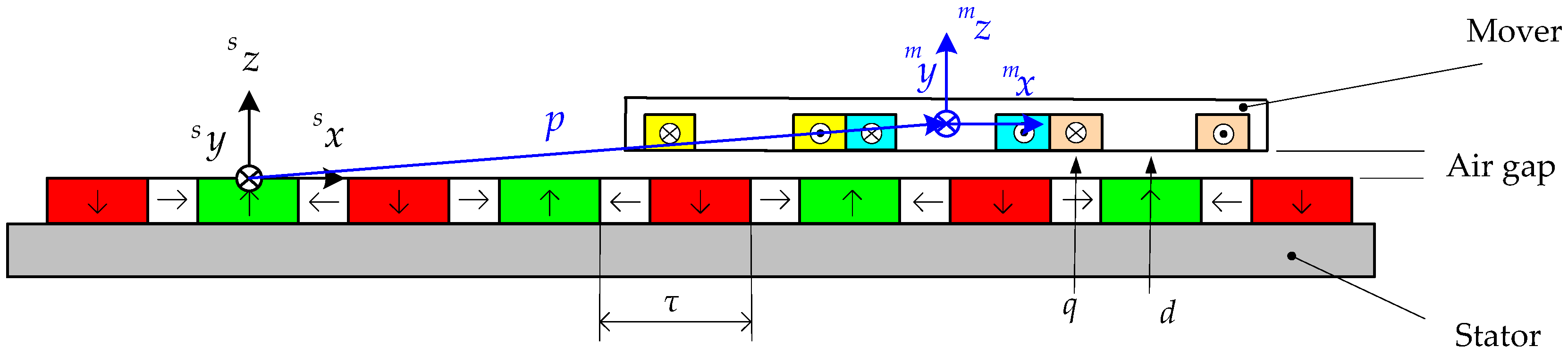
Figure 2.
Top views and A-A view of the components of a maglev linear motor: a Halbach array and a coil. Point Mj is the position in the local coordinate system.
Figure 2.
Top views and A-A view of the components of a maglev linear motor: a Halbach array and a coil. Point Mj is the position in the local coordinate system.
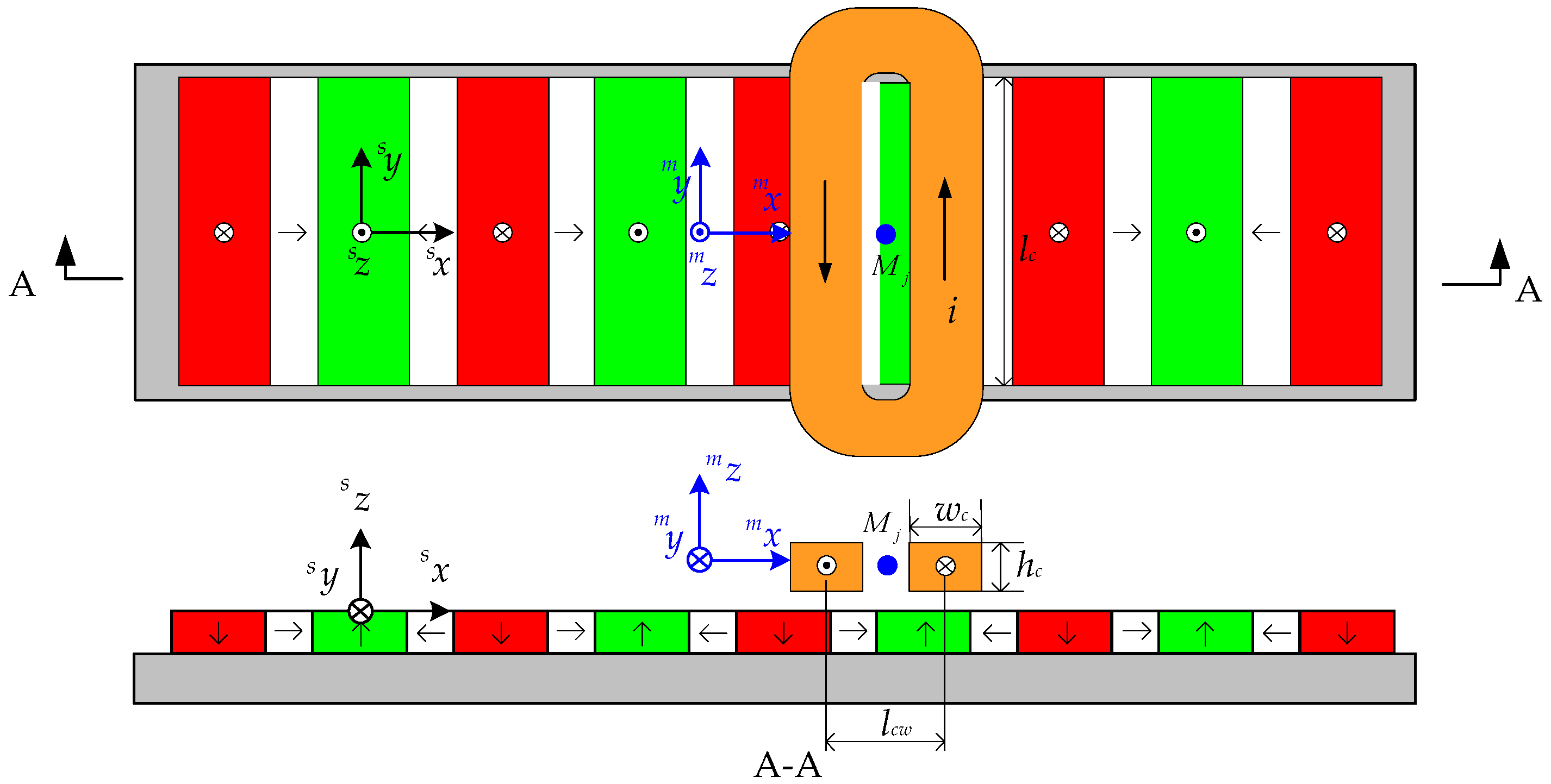
Figure 3.
Additional torque caused by id and iq.
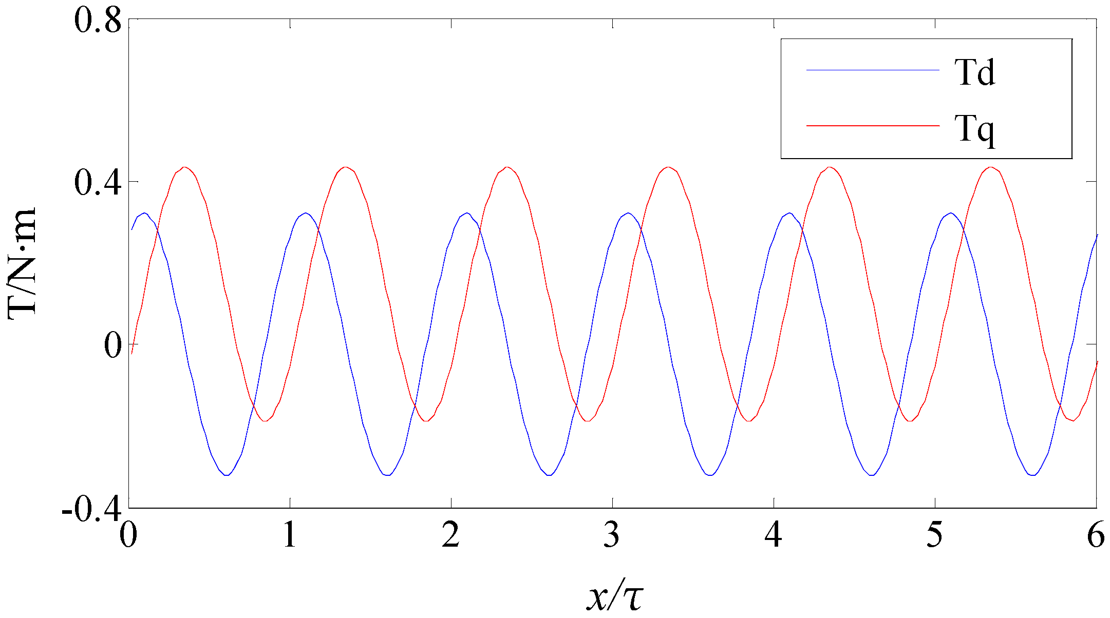
Figure 4.
Basic structure of the proposed maglev linear motor.

Figure 5.
Structure and arrangement of the two sets of windings.

Figure 6.
Selection of the permanent magnet array variable.

Figure 7.
Force coefficient curve in terms of permanent magnet size.

Figure 8.
Force coefficient k curve with respect to the thickness of permanent magnet.

Figure 9.
Force coefficient k curve with respect to the thickness of coil.

Figure 10.
Additional torque generated by the unit I and the unit II.
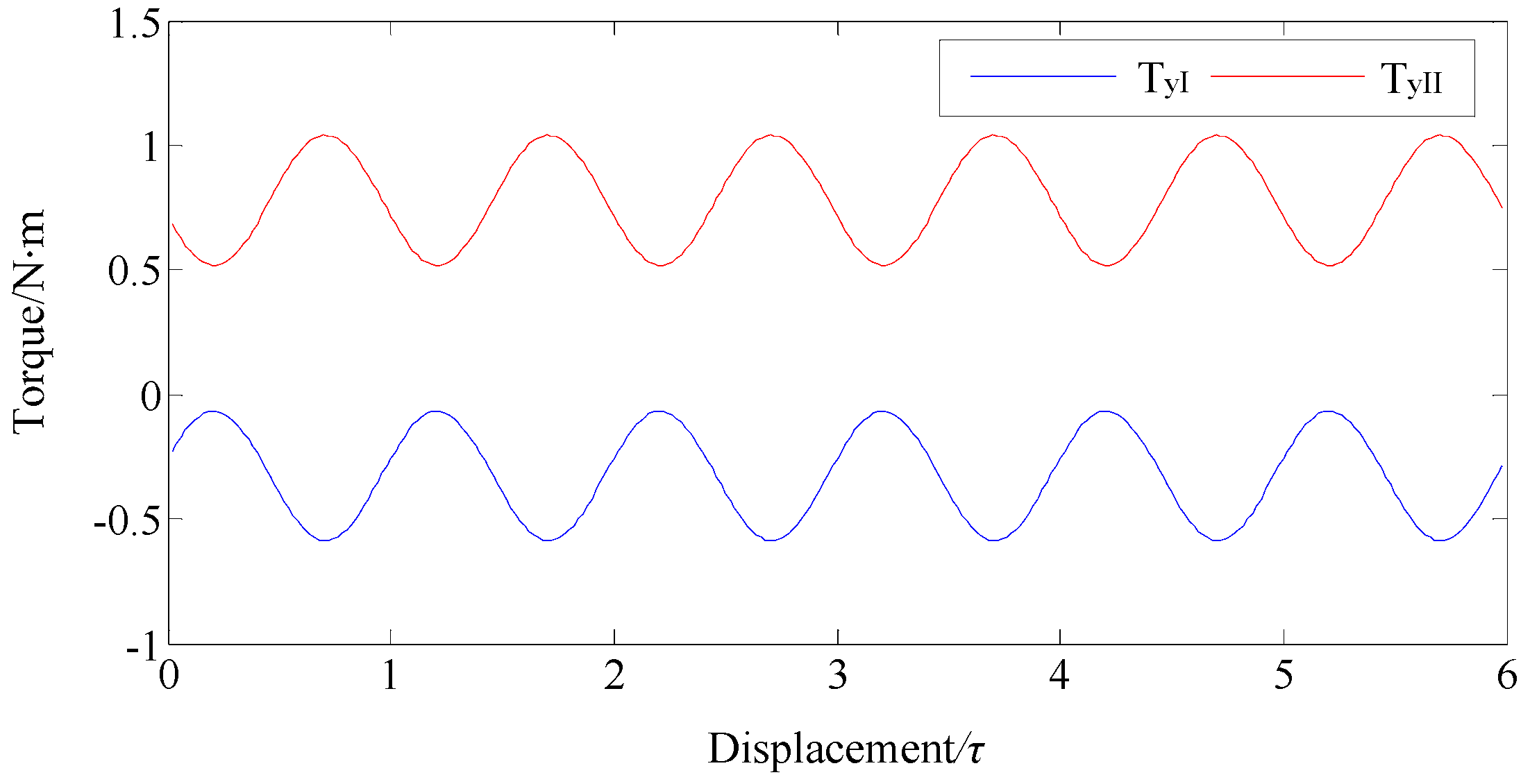
Figure 11.
Electromagnetic force and torque: (a) electromagnetic thrust force Fx and levitation force Fz; (b) torque Ty.
Figure 11.
Electromagnetic force and torque: (a) electromagnetic thrust force Fx and levitation force Fz; (b) torque Ty.

Figure 12.
Control system structure.

Figure 13.
Three degrees-of-freedom (DOF) position close-loop simulation result: (a) position and angle; (b) electromagnetic force and torque.
Figure 13.
Three degrees-of-freedom (DOF) position close-loop simulation result: (a) position and angle; (b) electromagnetic force and torque.


Table 1.
Motor major parameters.
| Parameter | Value | Unit |
|---|---|---|
| Pole pitch τ | 15 | mm |
| Winding size (lc × wc × hc) | 100 × 5 × 10 | mm |
| Major permanent magnet size (lm1 × wm1 × hm) | 100 × 10 × 8 | mm |
| Auxiliary permanent magnet size (lm2 ×wm2 × hm) | 100 × 5 × 8 | mm |
| Air gap δ | 1 | mm |
Table 2.
Motor major parameters.
| Parameter | Value | Unit |
|---|---|---|
| Pole pitch τ | 15 | mm |
| Air gap δ | 1 | mm |
| Winding size (lc × wc × hc) | 100 × 5 × 12 | mm |
| Major permanent magnet size (lm1 × wm1 × hm) | 100 × 8.7 × 20 | mm |
| Auxiliary permanent magnet size (lm2 × wm2 × hm) | 100 × 6.3 × 20 | mm |
| Mover size (l × w × h) | 150 × 120 × 20 | mm |
| Mover mass | 2.1 | kg |
| Number of turns N | 100 | - |
Table 3.
Proportional-integral-derivative (PID) controller parameters.
| Parameter | Controller I | Controller II | Controller III |
|---|---|---|---|
| Kp | 98 | 98 | 223 |
| Ki | 0.1 | 0.1 | 0.07 |
| Kd | 1.5 | 1.5 | 3.6 |
© 2018 by the authors. Licensee MDPI, Basel, Switzerland. This article is an open access article distributed under the terms and conditions of the Creative Commons Attribution (CC BY) license (http://creativecommons.org/licenses/by/4.0/).
Share and Cite
MDPI and ACS Style
Xing, F.; Kou, B.; Zhang, L.; Wang, T.; Zhang, C. Analysis and Design of a Maglev Permanent Magnet Synchronous Linear Motor to Reduce Additional Torque in dq Current Control. Energies 2018, 11, 556. https://doi.org/10.3390/en11030556
AMA Style
Xing F, Kou B, Zhang L, Wang T, Zhang C. Analysis and Design of a Maglev Permanent Magnet Synchronous Linear Motor to Reduce Additional Torque in dq Current Control. Energies. 2018; 11(3):556. https://doi.org/10.3390/en11030556
Chicago/Turabian StyleXing, Feng, Baoquan Kou, Lu Zhang, Tiecheng Wang, and Chaoning Zhang. 2018. "Analysis and Design of a Maglev Permanent Magnet Synchronous Linear Motor to Reduce Additional Torque in dq Current Control" Energies 11, no. 3: 556. https://doi.org/10.3390/en11030556
Note that from the first issue of 2016, this journal uses article numbers instead of page numbers. See further details here.