An Experimental Investigation of Hydraulic Fracturing in Shale Considering Anisotropy and Using Freshwater and Supercritical CO2


1
Key Laboratory of Shale Gas and Geoengineering, Institute of Geology and Geophysics, Chinese Academy of Sciences, Beijing 100029, China
2
Institutions of Earth Science, Chinese Academy of Sciences, Beijing 100029, China
3
University of Chinese Academy of Sciences, Beijing 100049, China
*
Authors to whom correspondence should be addressed.
Energies 2018, 11(3), 557; https://doi.org/10.3390/en11030557
Submission received: 10 November 2017
/
Revised: 25 January 2018
/
Accepted: 1 March 2018
/
Published: 5 March 2018
Abstract
:The process of hydraulic fracturing makes use of a liquid to fracture reservoir rocks for the exploitation of unconventional resources. Hence, it is vital to understand the processes that produce the fracture networks that occur during hydraulic fracturing. A shale reservoir is one of the largest unconventional resources and it displays obvious anisotropic characteristics due to its inherent sedimentary structures. The viscosity and flow ability of the fracturing fluid plays an important role in this process. We conducted a series of hydraulic fracturing tests on shale cores (from the southern Sichuan Basin) using freshwater and supercritical CO2 (SCO2) as fracturing fluids to investigate the different modes of fracture propagation. The pump pressure curves that we obtained during the fracturing experiment show how the shale responded to each of the fracturing fluids. We examined the influence of the anisotropic characteristics on the propagation of hydraulic fractures by conducting a series of hydraulic fracturing experiments on the shale cores using different bedding orientations. The bedding orientation of the shale had a profound influence on the fracture propagation when using either freshwater or a SCO2 fluid. The breakdown pressure of the shale core was affected not only by the bedding orientation but also by the fracturing fluid. A macroscopic observation of the fractures revealed different fracture geometries and propagation patterns. The results demonstrated that the anisotropic structures and the fracturing fluids could influence the path of the hydraulic fracture.
1. Introduction
The poor permeability of shale rock [1,2] and different boundary conditions present many challenges during shale gas exploitation. Hydraulic fracturing has become a common and widespread technique for reservoir stimulation. Therefore, it is vital to understand the processes that produce the fracture networks that occur during hydraulic fracturing [3]. One of the most widely used fracturing fluids is freshwater. However, problems or concerns, such as water shortages [4], clay mineral swelling [5], and flowback water pollution [6], are associated with freshwater fracturing. Alternative fracturing fluids include CO2 foams, supercritical CO2 (SCO2), conventional liquid CO2, gelled fluids, viscoelastic surfactant (VES)-based fluids, and nitrogen-based foam, each with its own advantages and disadvantages (see [7]).
Both SCO2 and conventional liquid CO2 fracturing use 100% CO2 as the fracturing fluid. One of the most important advantages of liquid CO2 fracturing is the elimination of the formation damage common with fracturing fluids. Above its critical temperature of 31.10 °C and pressure of 7.39 MPa, CO2 acts like a supercritical fluid. Above this critical temperature and pressure, CO2 will expand like a gas but retain the density of a liquid. SCO2 is a promising alternative to freshwater for shale reservoir fracturing, because of its characteristic low viscosity and strong diffusivity. Furthermore, SCO2 can flow into many of the micro-fractures that liquid CO2 cannot infiltrate, and connect additional fractures to form a network. Furthermore, Middleton [8] observed that “using SCO2 can result in up to five times more gas production compared to aqueous fluids”. Li et al. [9] “conducted hydraulic fracturing in shale using different fracturing fluids (H2O, CO2, and N2)”. The authors obtained results that showed how these three stimulation fluids affect the breakdown pressure and the subsequent morphology of the fracture networks. Ishida et al. [10,11] conducted fracturing experiments using SCO2 and liquid CO2 in cubic granite blocks. The results indicated that the SCO2 and the liquid CO2 injections, when compared with a freshwater injection, spread over a larger area. Kizaki et al. [12] conducted fracturing experiments with SCO2 and freshwater on cubic Inada granite and Ogino tuff. The results suggested that both “the viscosity of the fracturing fluid and the weak planes of the rocks had an influence on the formation of the fractures”. Inui et al. [13] found that a “low viscosity fluid, such as SCO2, could induce a shear dominant fracture, while a high viscosity fluid could induce a tensile dominant fracture”. Chen et al. [14] microscopically observed the induced fractures of granite, further confirming that the viscosity of the fracturing fluid affects the fracture propagation, and that the fracture induced by SCO2 has more branches along the fracture than a fracture produced by freshwater and viscous oil. Skurtveit et al. [15] investigated the SCO2 breakthrough and the flow mechanisms in shale. They discovered that the pressure-induced micro-fractures that occurred during the breakthrough process, in addition to the capillary displacement, are important flow mechanisms.
For decades, laboratory experiments have been used to study hydraulic fracturing using freshwater as a fracturing fluid [3,16,17,18,19,20,21,22]. Various studies [23,24,25,26,27,28,29] investigated important factors (such as rock structure, in situ stress, viscosity, and the injection rate of a fracturing fluid) that affect the hydraulic fracturing process. Most of the aforementioned studies focused on the interactions between hydraulic fractures and pre-existing fractures, or the influence of boundary conditions on the subsequent fracture network. Renard et al. [30] showed that the propagation of hydraulic fractures in a limestone core was a result of the linkage of the pores. According to [31], the induced cloud of acoustic emission was due to a hydraulic fracture in the direction parallel to the bedding plane occurring faster than the fractures perpendicular to the bedding plane, which was attributed to the anisotropy of the sandstone. Chitrala et al. [32] revealed the effects of the bedding plane and the scale of the anisotropy of the reservoir rocks on the direction of the fracture propagation.
Shale is a typical anisotropic rock. Previous studies have shown that properties such as the compressive strength, Young’s modulus, and Poisson’s ratio vary with the variation of the bedding orientation [33,34,35]. The results of a Brazilian test [36,37] on shale also showed that the bedding orientation has an effect on the failure strength of shale. Because of the potential of SCO2 to create more complex fractures with a larger fracturing area in shale, in this study fracturing experiments using SCO2 as a fracturing fluid were carried out in order to investigate the influence of the transverse anisotropy of shale on the fracture propagation. To achieve this, we conducted fracturing tests on shale cores with a dimension of about 100 mm (height) × 50 mm (diameter). This paper presents: (a) the results of the fracturing experiments on the shale cores conducted using freshwater and SCO2; (b) the influence of the anisotropy on the fracture propagation; (c) an analysis of the different fracture morphologies obtained in the fractured shale cores.
2. Experimental Methodology
2.1. Sample Preparation
Laboratory experiments serve as a common method to study the mechanisms of fracture propagation and allow boundary conditions to be controlled in a more flexible way. In our experimental design, hydraulic fracturing experiments using freshwater and SCO2 were conducted on shale cores with different bedding angles to investigate the fracture propagation. As remarked by [38]: “The depth of the shale formation to be hydraulically fractured is usually thousands of meters, so proper retrieval of shale cores is sometimes impossible and quite costly. In addition, the size of the cores may also be too small to meet the requirements of the experimental apparatus”. Therefore, to overcome these challenges, we obtained tight shale samples from the outcrops of a Longmaxi formation in Chongqin, China. According to [37], the shale formation has a well-defined bedding structure with a dip angle of about 70°. The laminations, which could be observed through an electron microscope, formed as a consequence of sedimentation in the shale having a thickness of approximately 1.0 mm and normally occurring as parallel planar structures, as shown in Figure 1a. Shale blocks of about 400 mm × 400 mm × 400 mm were taken for the coring.
The fracturing experiments were conducted on shale cores. The dimension of the shale core was about 100 mm in height and 50 mm in diameter. A water-cooled diamond core drill was used to drill the shale cores. We used a water-flushed diamond saw blade to cut the end surfaces of the shale cores. In addition, the end surfaces were ground coplanar to a maximum deviation of ±0.02 mm. Shale cores with different bedding orientations (Figure 1b) were drilled from the shale blocks using different orientation angles (0°, 15°, 30°, 45°, 60°, 75°, and 90°). The intersection between the orientation plane and the drilling direction was easy to determine because the bedding planes were easily observable on the surfaces of the blocks. A borehole with a diameter of 5 mm was drilled from the top of the shale core to a depth of 50 mm along the central axis of the shale core for the injection of the fracturing fluid, as shown in Figure 2a. The photograph of the shale core with a borehole in place is shown in Figure 2b.
2.2. Experimental Procedures
We conducted the experiments through a triaxial rock testing system with pump pressurization for hydraulic fracturing using freshwater and SCO2 as the fracturing fluids. Before fracturing the shale cores, the samples were subjected to preset stress conditions (axial loading σv = 10 MPa, for the induction of the fracture development and confining pressure = 20 MPa, representing the uniform horizontal stress). The device used for injecting the fracturing fluid is shown in Figure 3a. The end side with the open borehole on the shale core was sealed with epoxy to ensure the reliability of the connection and to avoid any leakage of the fracturing fluid during the fracturing experiment. After the shale core was fixed on the loading frame of the testing system, we increased the axial stress to 10 MPa at a rate of 0.2 MPa/s. Then, we kept the stress state constant throughout the experiment. This was followed by injecting either freshwater or SCO2 at a constant rate of 10 mL/min into the shale core through the centrally placed borehole.
The testing system allowed for a triaxial loading of the shale cores with a simultaneous injection of fracturing fluid. Freshwater or SCO2, was injected into the borehole through the syringe pump, which had a maximum pressure and a flow capacity of 68.94 MPa and 50 mL/min, respectively. To attain the supercritical state needed for fracturing, liquid CO2 was initially pressurized and then heated to a temperature greater than 31.10 °C (Figure 4). The temperature of the pipeline for the transportation of heated SCO2 could be controlled to guarantee that the CO2 remains in a stable, supercritical state. In order to hydraulically fracture the shale core, the constant injection of the fracturing fluid lasted for several seconds after the peak pump pressure was attained. During the loading process, the axial stress and pump pressure were recorded every 0.1 s.
3. Results and Discussion
3.1. Anisotropic Characteristics of the Shale
The wave velocity and the anisotropic characteristics of the shale formation were measured using P and S as wave velocities. Ultrasonic tests were conducted to measure the P and S waves in the vertical direction for each shale core before drilling the borehole. Figure 5 shows the relationship between the wave velocities and the inclination angle of the bedding planes. The plot shows that the wave velocities varied from one bedding plane to another. In shale cores with a bedding plane of 90°, the average P and S wave velocities were 4171 m/s and 2767 m/s. In shale cores with a bedding plane of 0°, the average P and S wave velocities were 4049 m/s and 2752 m/s, respectively. These values were slightly lower than those measured in with shale cores with a bedding plane of 90°. Vernik and Liu [39] obtained similar results. The lowest values of P and S wave velocities were obtained when the orientation of the lamination was 60°. The wave velocities depend on the material properties of the rock, such as its elastic properties, which are also influenced by the mineralogical composition and the bedding orientation.
Unconfined compressive strength (UCS) is the capacity of a rock to resist compression without confining pressure. Brazilian Tensile Strength (BTS) is the capacity of a rock to resist tension, which can be indirectly measured. BTS and UCS are elementary mechanics performance indexes and an important basis for the anisotropy of rocks. Table 1 shows the UCS and BTS of the shale cores. The table demonstrates that the average BTS decreased with an increase in the orientation of the lamination. However, the BTS slightly increased when the orientation of the lamination was increased from 75° to 90°. The lowest average BTS value was obtained when the orientation of the lamination was 75°. The average UCS of the shale core ranged from 111.85 MPa to 52.29 MPa, showing an increasing trend with an increasing orientation of the lamination from 0° to 30°; when the maximum value was attained, a further increase in the orientation of the lamination from 45° to 60° corresponded to a decrease of the trend. When the orientation of the lamination was 75°, the average UCS increased, then slightly reduced when the orientation of the lamination reached 90°. The lowest UCS value was obtained when the orientation of the lamination was 60°. Wasantha et al. [40] also observed the lowest UCS when the joint orientation was 60°. The breakdown pressure of the rock shale core with different bedding orientations, during the hydraulic fracturing experiment, was influenced by the mechanical properties of the rock shale core.
3.2. Experimental Monitoring of Hydraulic Fracturing
Figure 6 shows the relationship between the pump pressure and time during the hydraulic fracturing process under the axial stress of 10 MPa and an injection rate of 10 mL/min using freshwater as the fracturing fluid. Injecting the fracturing fluid (freshwater) at a constant flow rate increased the wellbore pressure, which peaked at the breakdown pressure, then fractured the samples and led to the failure of the samples. At the beginning of the fracturing process (Figure 6), the pump pressure was zero. It increased sharply as a result of the filling of the borehole. The pump pressure then increased rapidly with time until the peak pressure was attained (breakdown pressure). As soon as the sample was fractured (at the breakdown pressure), there was a rapid reduction in the pressure in the borehole because of the high permeation along the visible fractures. We stopped the fluid injection once the shale core had been fractured. The peak pump pressure and its corresponding time varied with the bedding orientation of the shale core.
Figure 7 shows the relationship between the pump pressure and time during the fracturing process using SCO2 as the fracturing fluid. The axial stress and injection rate were 10 MPa and 10 mL/min, respectively. The SCO2 fracturing process was similar to the freshwater fracturing process. The obvious difference between SCO2 and freshwater fracturing was the time gap in the fracturing process between the shale cores with different bedding orientations. The fracturing time using SCO2 was greater than the fracturing time using freshwater. This was mainly caused by the volume contraction of the SCO2 with the increase of the pump pressure.
Figure 8 shows the plot of the breakdown pressure against the bedding orientation. The graph shows that an inverse relationship exists between the breakdown pressure and the bedding plane orientation. The maximum breakdown pressure occurred when the bedding plane was perpendicular to the loading direction. However, there was a slight increase in the breakdown pressure when the bedding plane orientation increased from 60° to 90°.
This trend was observed while using both fracturing fluids. This phenomenon can be explained as follows: when the bedding plane orientation angles are low, the fractures largely propagate through the rock matrix. By increasing the bedding orientation, the fracturing processes make use of the bedding planes, which should have a weaker tensile strength than the rock matrix. In addition, the breakdown pressure of the samples fractured using freshwater was higher than the breakdown pressure of the samples fractured using SCO2. The disparities between the breakdown pressure of samples fractured by freshwater and SCO2 were in the range of 6.3–11.2 MPa. The maximum and minimum values corresponded to the shale core with a bedding orientation of 45° and 90°, respectively.
3.3. Fracture Propagation of Hydraulic Fracturing
Fracture propagation is crucial for understanding the mechanism behind the formation of hydraulic fractures. The influence of the bedding plane orientation on the fractures formed during hydraulic fracturing, using freshwater and SCO2, are shown in Table 2. Macroscopic fractures induced by the pump pressure on the surface of the shale cores were observed and marked with red lines. Different types of fracture propagation modes (Table 2) were formed because of the different bedding orientations and fracturing fluids. The types of fracture propagation observed after the shale cores’ failure were:
- Curved fractures: these cracks are slightly curved and deviated from the loading direction.
- Layer-activated fractures: these are straight or slightly straight fractures that propagated along the bedding plane and the rock matrix.
- Central-linear fractures: fractures that propagated along the loading direction.
Curved fractures are tensile in nature, propagated through the rock matrix, and were commonly observed when SCO2 was used as the fracturing fluid. Layer-activated fractures are mixed tensile–shear cracks and were observed when freshwater was used as the fracturing fluid. The mode of propagation of layer-activated fractures along the bedding plane and the rock matrix are shearing and tension, respectively. Central-linear fractures propagated in the tensile mode and through the rock matrix when the bedding plane orientation was 0°, and propagated along the bedding plane when the bedding plane orientation was 90°. The rock matrix was replaced by the bedding plane as the main controlling factor in the shale for the hydraulic fracturing process of the shale.
3.4. Assessment of the the Fracture Surface
We selected tortuosity as the main parameter to quantitatively measure the morphology of the hydraulic fractures. Chen et al. [14] defined tortuosity “as the total fracture length along a pathway divided by the direct length of the two ends in the reference area”. In a three-dimensional (3D) situation, the area, instead of the fracture length, can be used for measuring the tortuosity of the fractured surface. We used a 3D scanner to generate a point cloud of the surface of the shale samples. A laser was used to generate a pulse of light, and we measured the time it took for the reflection to be detected by a detector. The distance of a surface is determined using the scanner, and this is achieved by timing the round-trip time of a pulse of light. These points can then be used to reconstruct the shape of the fracture surface by joining neighboring points together with straight lines to create a continuous surface. The scanning results were used for the tortuosity quantification of the fractures. The tortuosity Rc can be defined as:
where Rz and Rt are the real and projected areas of the fracture surface, respectively.
All the projected areas of the fractured surfaces were the same, with a value of 5000 mm2. Only the shale cores with a bedding orientation of 30° and 90° were scanned. We compared the tortuosity of the fractures produced by the different fracturing fluids. The results are presented in Table 3. The tortuosity of the fractures produced by SCO2 fracturing was greater than the tortuosity of the fractures produced by freshwater fracturing. This result is displayed using reconstructed contour plots of the fracture surfaces (Figure 9). The contour plots of the fracture surfaces reflect their tortuosity. The fluctuation of the contour elevation in Figure 9a is greater than in Figure 9b, which can be attributed to the different modes of the fracture propagation. The fracture propagation in the shale core with a bedding orientation of 30° was mainly in mixed mode (tensile and shearing) across the layered rock matrix. On the other hand, the fracture propagation in the shale core with a bedding orientation of 90° was mainly in tension mode along the bedding plane. The contour lines in the plots shown in Figure 9 indicate: (1) the fracture surface produced by SCO2 fracturing was more irregular, with a bigger tortuosity, than the fracture surface produced by freshwater fracturing, regardless of the bedding orientation; (2) the fracture surface formed in the shale core with a bedding orientation of 90° developed along the bedding plane, regardless of the fracturing fluid.
4. Conclusions
In this study, hydraulic fracturing tests were conducted to study the effect of shale anisotropic characteristics on the fracture propagation using two different fracturing fluids. The anisotropy caused by bedding orientations and different fracturing fluids can influence the pathway of the fracture. Irrespective of the fracturing fluid, the bedding orientation of the shale has an obvious influence on the fracture propagation. Different fracture modes, such as curved, layer-activated, and central–linear fractures were observed during the fracturing process. The breakdown pressure of the shale cores was affected not only by the bedding orientation but also by the fracturing fluid. Generally, it decreased with an increase in the bedding orientation and slightly increased when the bedding plane orientation was increased from 60° to 90°. In addition, the breakdown pressure of the shale cores fractured by freshwater was higher than the breakdown pressure of the shale cores fractured by SCO2. Finally, the fracture surface of the fractures produced by the SCO2 was irregular and with a higher value of tortuosity, regardless of the bedding orientation.
Acknowledgments
This work was supported by the National Natural Science Foundation of China (Grant Nos. 41572310 and 41227901), the Strategic Priority Research Program of the Chinese Academy of Sciences (Grant Nos. XDB10030301 and XDB10030304) and the National Science and Technology Major Project (Grant No. 2016ZX05034-003).
Author Contributions
Jianming He conceived and designed the experiments; Chong Lin and Xiaole Wan performed the experiments and analyzed the data; Lekan Olatayo Afolagboye and Jianming He analyzed the data and wrote the paper.
Conflicts of Interest
The authors declare no conflict of interest.
References
- Chen, L.; Kang, Q.; Dai, Z.; Viswanathan, H.S.; Tao, W. Permeability prediction of shale matrix reconstructed using the elementary building block model. Fuel 2015, 160, 346–356. [Google Scholar] [CrossRef]
- Singh, H.; Javadpour, F. Langmuir slip-Langmuir sorption permeability model of shale. Fuel 2016, 164, 28–37. [Google Scholar] [CrossRef]
- Warpinski, N.R.; Teufel, L.W. Influence of geologic discontinuities on hydraulic fracture propagation (includes associated papers 17011 and 17074). J. Pet. Technol. 1987, 39, 209–220. [Google Scholar] [CrossRef]
- Scanlon, B.R.; Reedy, R.C.; Nicot, J.-P. Comparison of water use for hydraulic fracturing for unconventional oil and gas versus conventional oil. Environ. Sci. Technol. 2014, 48, 12386–12393. [Google Scholar] [CrossRef] [PubMed]
- Wang, H.; Li, G.; Shen, Z. A Feasibility analysis on shale gas exploitation with supercritical carbon dioxide. Energy Sources Part A Recover. Util. Environ. Eff. 2012, 34, 1426–1435. [Google Scholar] [CrossRef]
- Jackson, R.E.; Gorody, A.W.; Mayer, B.; Roy, J.W.; Ryan, M.C.; Van Stempvoort, D.R. Groundwater protection and unconventional gas extraction: The critical need for field-based hydrogeological research. Groundwater 2013, 51, 488–510. [Google Scholar] [CrossRef] [PubMed]
- Li, H.; Lau, H.C.; Huang, S. Coalbed Methane Development in China: Engineering Challenges and Opportunities. In Proceedings of the SPE/IATMI Asia Pacific Oil & Gas Conference and Exhibition (APOGCE), Jakarta, Indonesia, 17–19 October 2017. [Google Scholar]
- Middleton, R.; Viswanathan, H.; Currier, R.; Gupta, R. CO2 as a fracturing fluid: Potential for commercial-scale shale gas production and CO2 sequestration. Energy Procedia 2014, 63, 7780–7784. [Google Scholar] [CrossRef]
- Li, X.; Feng, Z.; Han, G.; Elsworth, D.; Marone, C.; Saffer, D. Hydraulic Fracturing in Shale with H2O, CO2 and N2. In Proceedings of the 49th US Rock Mechanics/Geomechanics Symposium, San Francisco, CA, USA, 28 June–1 July 2015. ARMA 15-786. [Google Scholar]
- Ishida, T.; Aoyagi, K.; Niwa, T.; Chen, Y.; Murata, S.; Chen, Q.; Nakayama, Y. Acoustic emission monitoring of hydraulic fracturing laboratory experiment with supercritical and liquid CO2. Geophys. Res. Lett. 2012, 39, L16309. [Google Scholar] [CrossRef]
- Ishida, T.; Nagaya, Y.; Inui, S.; Aoyagi, K.; Nara, Y.; Chen, Y.; Chen, Q.; Nakayama, Y. AE Monitoring of Hydraulic Fracturing Experiments Conducted Using CO2 and water. In Rock Mechanics for Resources, Energy and Environment; CRC Press: Boca Raton, FL, USA, 2013; pp. 957–962. ISBN 978-1-138-00080-3. [Google Scholar]
- Kizaki, A.; Tanaka, H.; Ohashi, K.; Sakaguchi, K.; Matsuki, K. Hydraulic Fracturing in Inada Granite and Ogino Tuff with Super Critical Carbon Dioxide. In Proceedings of the ISRM Regional Symposium-7th Asian Rock Mechanics Symposium (ARMS7), Seoul, Korea, 15–19 October 2012. [Google Scholar]
- Inui, S.; Ishida, T.; Nagaya, Y.; Nara, Y.; Chen, Y.; Chen, Q. AE monitoring of Hydraulic Fracturing Experiments in Granite Blocks Using Supercritical CO2, Water and Viscous Oil. In Proceedings of the 48th U.S. Rocks Mechanics/Geomechanics Symposium, Minneapolis, MN, USA, 1–4 June 2014. [Google Scholar]
- Chen, Y.; Nagaya, Y.; Ishida, T. Observations of Fractures Induced by Hydraulic Fracturing in Anisotropic Granite. Rock Mech. Rock Eng. 2015, 48, 1455–1461. [Google Scholar] [CrossRef]
- Skurtveit, E.; Aker, E.; Soldal, M.; Angeli, M.; Wang, Z. Experimental investigation of CO2 breakthrough and flow mechanisms in shale. Pet. Geosci. 2012, 18, 3–15. [Google Scholar] [CrossRef]
- Lamont, N.; Jessen, F.W. The effects of existing fractures in rocks on the extension of hydraulic fractures. J. Pet. Technol. 1963, 15, 203–209. [Google Scholar] [CrossRef]
- Blanton, T.L. An Experimental Study of Interaction between Hydraulically Induced and Pre-Existing Fractures. In Proceedings of the SPE Unconventional Gas Recovery Symposium, Pittsburgh, PA, USA, 6–18 May 1982; pp. 559–571. [Google Scholar]
- Gale, J.F.W.; Reed, R.M.; Holder, J. Natural fractures in the Barnett Shale and their importance for hydraulic fracture treatments. AAPG Bull. 2007, 91, 603–622. [Google Scholar] [CrossRef]
- Zhou, J.; Chen, M.; Jin, Y.; Zhang, G. Analysis of fracture propagation behavior and fracture geometry using a tri-axial fracturing system in naturally fractured reservoirs. Int. J. Rock Mech. Min. Sci. 2008, 45, 1143–1152. [Google Scholar] [CrossRef]
- Dehghan, A.N.; Goshtasbi, K.; Ahangari, K.; Jin, Y. Experimental investigation of hydraulic fracture propagation in fractured blocks. Bull. Eng. Geol. Environ. 2015, 74, 887–895. [Google Scholar] [CrossRef]
- Liu, Z.; Chen, M.; Zhang, G. Analysis of the influence of a natural fracture network on hydraulic fracture propagation in carbonate formations. Rock Mech. Rock Eng. 2014, 47, 575–587. [Google Scholar] [CrossRef]
- Chuprakov, D.; Melchaeva, O.; Prioul, R. Injection-sensitive mechanics of hydraulic fracture interaction with discontinuities. Rock Mech. Rock Eng. 2014, 47, 1625–1640. [Google Scholar] [CrossRef]
- Gupta, A.P.; Gupta, A.; Langlinais, J. Feasibility of Supercritical Carbon Dioxide as a Drilling Fluid for Deep Underbalanced Drilling Operation. In Proceedings of the SPE Annual Technical Conference and Exhibition, Dallas, TX, USA, 22–25 October 1995. [Google Scholar]
- Olson, J.E.; Bahorich, B.; Holder, J. Examining Hydraulic Fracture: Natural Fracture Interaction in Hydrostone Block Experiments. In Proceedings of the 2012 SPE Hydraulic Fracturing Technology Conference, The Woodlands, TX, USA, 6–8 February 2012. [Google Scholar]
- Guo, T.; Zhang, S.; Qu, Z.; Zhou, T.; Xiao, Y.; Gao, J. Experimental study of hydraulic fracturing for shale by stimulated reservoir volume. Fuel 2014, 128, 373–380. [Google Scholar] [CrossRef]
- Fan, T.; Zhang, G. Laboratory investigation of hydraulic fracture networks in formations with continuous orthogonal fractures. Energy 2014, 74, 164–173. [Google Scholar] [CrossRef]
- Bennour, Z.; Ishida, T.; Nagaya, Y.; Chen, Y.; Nara, Y.; Chen, Q.; Sekine, K.; Nagano, Y. Crack extension in hydraulic fracturing of shale cores using viscous oil, water, and liquid carbon dioxide. Rock Mech. Rock Eng. 2015, 48, 1463–1473. [Google Scholar] [CrossRef] [Green Version]
- Alabbad, E.A.; Olson, J.E. Examining the Geomechanical Implications of Pre-Existing Fractures and Simultaneous-Multi-Fracturing Completions on Hydraulic Fractures: Experimental Insights into Fracturing Unconventional Formations. In Proceedings of the 2016 SPE Hydraulic Fracturing Technology Conference, The Woodlands, TX, USA, 9–11 February 2016; pp. 6–8. [Google Scholar]
- Liu, E. Effects of fracture aperture and roughness on hydraulic and mechanical properties of rocks: Implication of seismic characterization of fractured reservoirs. J. Geophys. Eng. 2005, 2, 38. [Google Scholar] [CrossRef]
- Renard, F.; Bernard, D.; Desrues, J.; Ougier-Simonin, A. 3D imaging of fracture propagation using synchrotron X-ray microtomography. Earth Planet. Sci. Lett. 2009, 286, 285–291. [Google Scholar] [CrossRef]
- Stanchits, S.; Mayr, S.; Shapiro, S.; Dresen, G. Fracturing of porous rock induced by fluid injection. Tectonophysics 2011, 503, 129–145. [Google Scholar] [CrossRef]
- Chitrala, Y.; Moreno, C.; Sondergeld, C.H.; Rai, C.S. Microseismic Mapping of Laboratory Induced Hydraulic Fractures in Anisotropic Reservoirs. In Proceedings of the 2010 Tight Gas Completions Conference, San Antonio, TX, USA, 2–3 November 2010. [Google Scholar]
- Niandou, H.; Shao, J.F.; Henry, J.P.; Fourmaintraux, D. Laboratory investigation of the mechanical behaviour of Tournemire shale. Int. J. Rock Mech. Min. Sci. 1997, 34, 3–16. [Google Scholar] [CrossRef]
- Sayers, C.M. The effect of anisotropy on the Young’s moduli and Poisson’s ratios of shales. Geophys. Prospect. 2013, 61, 416–426. [Google Scholar] [CrossRef]
- Chuanliang, Y.; Jingen, D.; Lianbo, H.; Zijian, C.; Xinjiang, Y.; Hai, L.; Qiang, T.; Baohua, Y. Brittle failure of shale under uniaxial compression. Arab. J. Geosci. 2015, 8, 2467–2475. [Google Scholar] [CrossRef]
- Cho, J.-W.; Kim, H.; Jeon, S.; Min, K.-B. Deformation and strength anisotropy of Asan gneiss, Boryeong shale, and Yeoncheon schist. Int. J. Rock Mech. Min. Sci. 2012, 50, 158–169. [Google Scholar] [CrossRef]
- He, J.; Afolagboye, L.O. Influence of layer orientation and interlayer bonding force on the mechanical behavior of shale under Brazilian test conditions. Acta Mech. Sin. 2017, 1–10. [Google Scholar] [CrossRef]
- He, J.; Lin, C.; Li, X.; Wan, X. Experimental investigation of crack extension patterns in hydraulic fracturing with shale, sandstone and granite cores. Energies 2016, 9, 1018. [Google Scholar] [CrossRef]
- Vernik, L.; Liu, X. Velocity anisotropy in shales: A petrophysical study. Geophysics 1997, 62, 521–532. [Google Scholar] [CrossRef]
- Wasantha, P.L.P.; Ranjith, P.G.; Viete, D.R. Effect of joint orientation on the hydromechanical behavior of singly jointed sandstone experiencing undrained loading. J. Geophys. Res. Solid Earth 2014, 119, 1701–1717. [Google Scholar] [CrossRef]
Figure 1.
(a) Laminations in the shale due to sedimentation; and (b) schematic diagram of the shale coring.
Figure 1.
(a) Laminations in the shale due to sedimentation; and (b) schematic diagram of the shale coring.
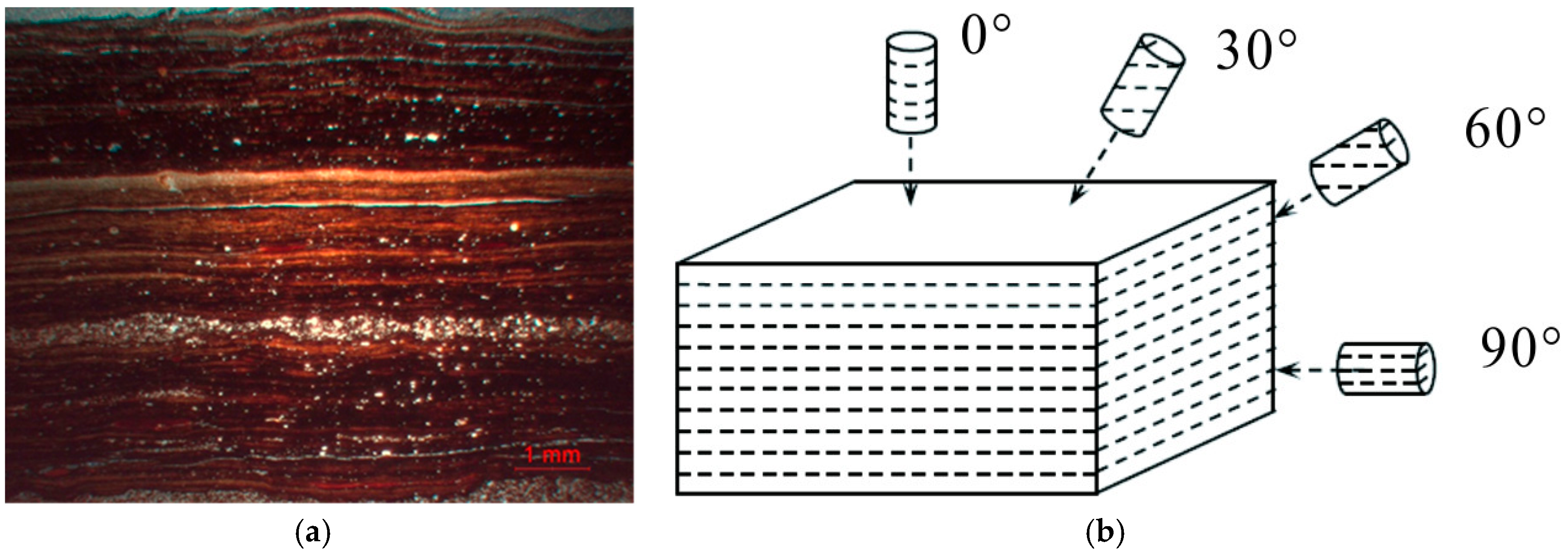
Figure 2.
(a) Profile of the shale core; and (b) photograph of the shale core.

Figure 3.
(a) The device that was used to inject the fracturing fluid; and (b) the shale core that was sealed with epoxy.
Figure 3.
(a) The device that was used to inject the fracturing fluid; and (b) the shale core that was sealed with epoxy.

Figure 4.
Preparation and transportation of the supercritical CO2 (SCO2) for the fracturing experiment.
Figure 4.
Preparation and transportation of the supercritical CO2 (SCO2) for the fracturing experiment.
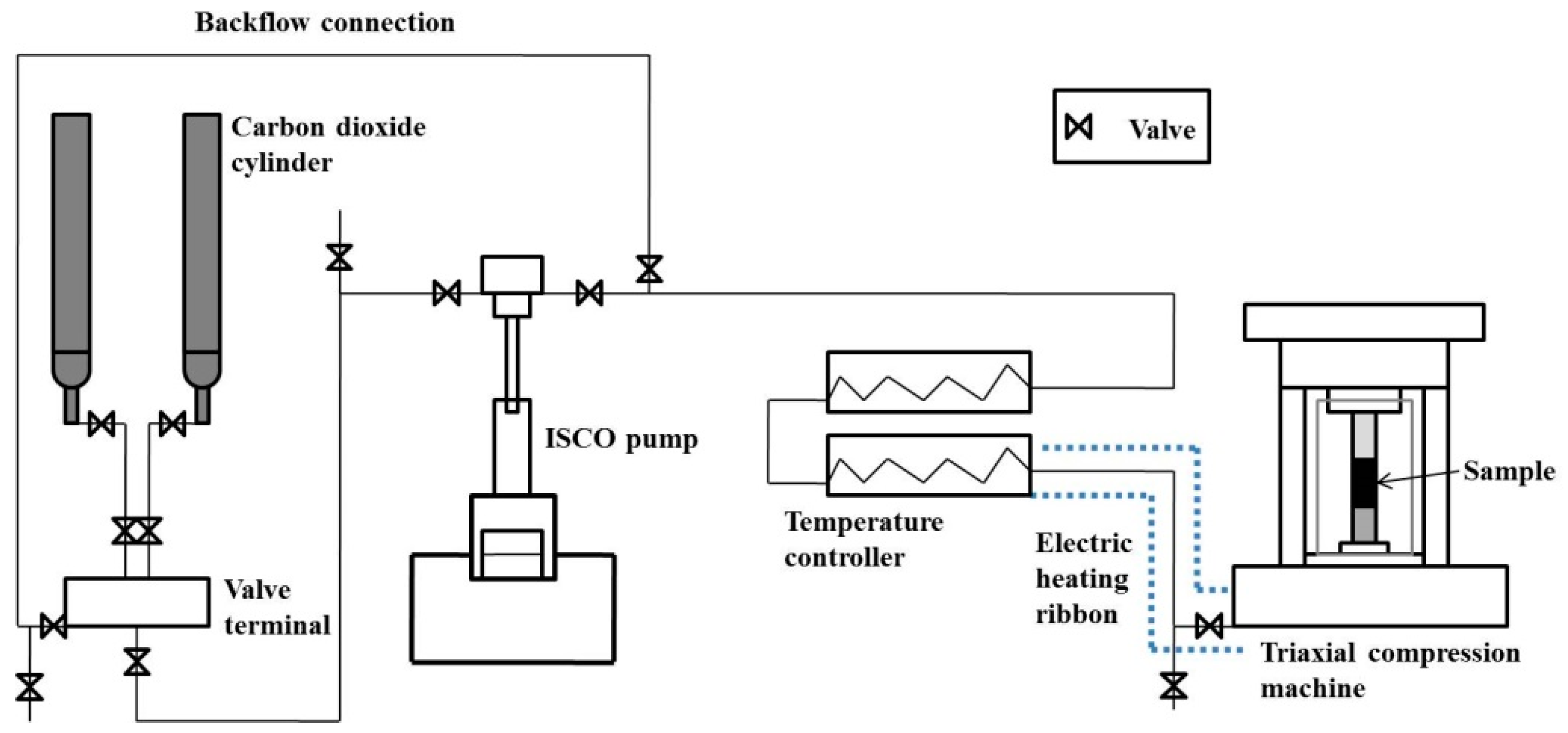
Figure 5.
The P and S wave velocities of the shale cores with different bedding orientations.
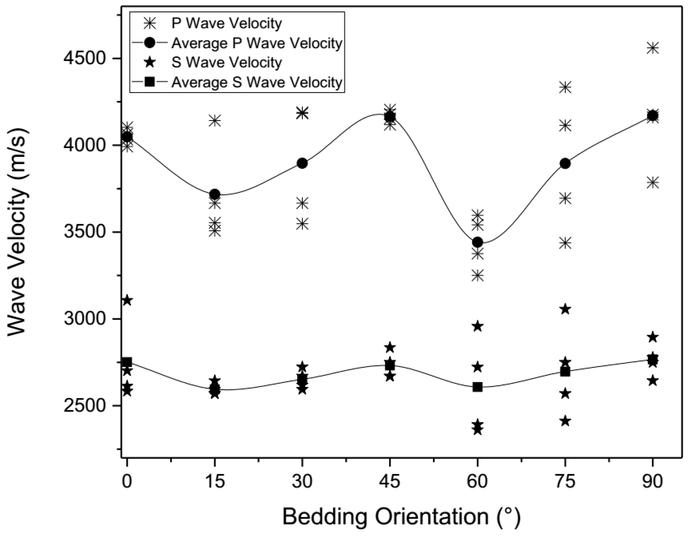
Figure 6.
Pump pressure development versus time under different bedding plane angles (freshwater as fracturing fluid).
Figure 6.
Pump pressure development versus time under different bedding plane angles (freshwater as fracturing fluid).
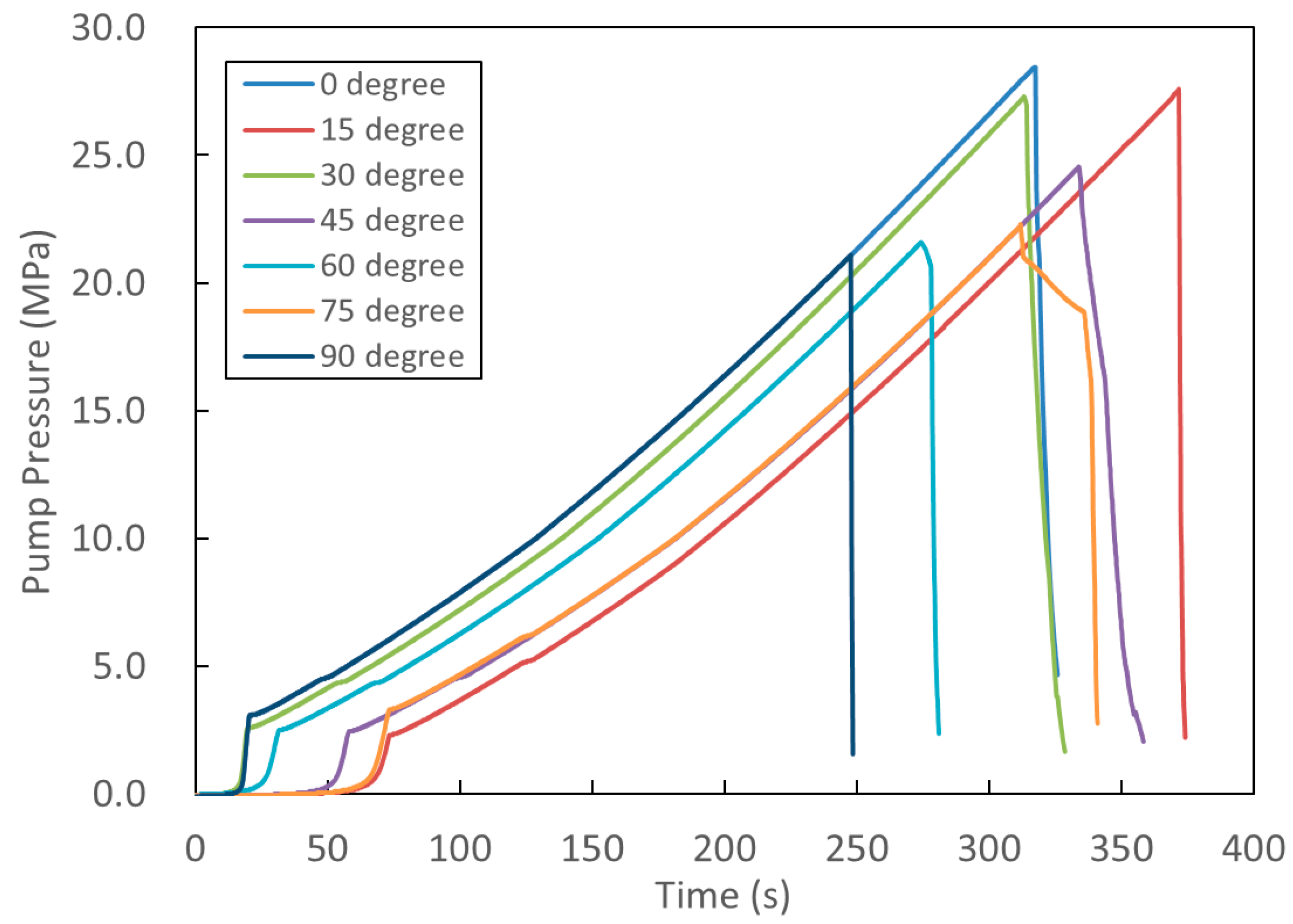
Figure 7.
Pump pressure development versus time under different bedding plane angles (SCO2 as the fracturing fluid).
Figure 7.
Pump pressure development versus time under different bedding plane angles (SCO2 as the fracturing fluid).
Figure 8.
Influence of the bedding orientation on the breakdown pressure.
Figure 9.
Contour plots of fracture surfaces with a bedding orientation of 30° and 90°. (a) Fractured by freshwater (30°); (b) fracture by SCO2 (30°); (c) fractured by freshwater (90°); and (d) fractured by SCO2 (90°).
Figure 9.
Contour plots of fracture surfaces with a bedding orientation of 30° and 90°. (a) Fractured by freshwater (30°); (b) fracture by SCO2 (30°); (c) fractured by freshwater (90°); and (d) fractured by SCO2 (90°).

Table 1.
Mechanical parameters of the anisotropic shale.
| Bedding Orientation | Average P Wave Velocity (m/s) | Average S Wave Velocity (m/s) | Uniaxial Compressive Strength (MPa) | Tensile Strength (MPa) |
|---|---|---|---|---|
| 0° | 4049 ± 46.6 | 2752 ± 242.3 | 108.06 ± 1.74 | 7.07 ± 0.99 |
| 15° | 3717 ± 290.8 | 2595 ± 39.4 | 110.85 ± 2.30 | 6.67 ± 1.01 |
| 30° | 3897 ± 337.6 | 2652 ± 57.1 | 111.85 ± 1.95 | 5.63 ± 1.06 |
| 45° | 4164 ± 36.8 | 2731 ± 78.9 | 97.06 ± 1.81 | 4.35 ± 0.98 |
| 60° | 3441 ± 158.0 | 2608 ± 284.6 | 52.29 ± 1.68 | 3.49 ± 0.66 |
| 75° | 3895 ± 404.3 | 2697 ± 276.0 | 91.78 ± 1.43 | 2.91 ± 0.43 |
| 90° | 4171 ± 316.4 | 2767 ± 102.9 | 90.37 ± 1.18 | 3.09 ± 0.37 |
Table 2.
Fractured shale cores by freshwater and SCO2 with different bedding orientations.
| Bedding Orientation | Fractured Using Freshwater | Fractured Using SCO2 | ||
|---|---|---|---|---|
| Photograph | Sketch | Photograph | Sketch | |
| 0° |  |  |  |  |
| 15° |  |  |  |  |
| 30° |  |  |  |  |
| 45° |  |  |  |  |
| 60° |  |  |  |  |
| 75° |  |  |  |  |
| 90° |  |  |  |  |
Table 3.
Tortuosity of the shale cores by freshwater and SCO2 fracturing with different bedding orientations.
Table 3.
Tortuosity of the shale cores by freshwater and SCO2 fracturing with different bedding orientations.
| Bedding Orientation | Fractured Using Freshwater | Fractured Using SCO2 | ||
|---|---|---|---|---|
| Real Area | Tortuosity | Real Area | Tortuosity | |
| 30° | 5428.50 | 1.09 | 6229.2 | 1.25 |
| 90° | 5176.44 | 1.04 | 5608.72 | 1.12 |
© 2018 by the authors. Licensee MDPI, Basel, Switzerland. This article is an open access article distributed under the terms and conditions of the Creative Commons Attribution (CC BY) license (http://creativecommons.org/licenses/by/4.0/).
Share and Cite
MDPI and ACS Style
He, J.; Afolagboye, L.O.; Lin, C.; Wan, X. An Experimental Investigation of Hydraulic Fracturing in Shale Considering Anisotropy and Using Freshwater and Supercritical CO2. Energies 2018, 11, 557. https://doi.org/10.3390/en11030557
AMA Style
He J, Afolagboye LO, Lin C, Wan X. An Experimental Investigation of Hydraulic Fracturing in Shale Considering Anisotropy and Using Freshwater and Supercritical CO2. Energies. 2018; 11(3):557. https://doi.org/10.3390/en11030557
Chicago/Turabian StyleHe, Jianming, Lekan Olatayo Afolagboye, Chong Lin, and Xiaole Wan. 2018. "An Experimental Investigation of Hydraulic Fracturing in Shale Considering Anisotropy and Using Freshwater and Supercritical CO2" Energies 11, no. 3: 557. https://doi.org/10.3390/en11030557
Note that from the first issue of 2016, this journal uses article numbers instead of page numbers. See further details here.