On Field Weakening Performance of a Brushless Direct Current Motor with Higher Winding Inductance: Why Does Design Matter?


1
Electrical Engineering Department, Istanbul Technical University, Istanbul 34467, Turkey
2
Electrical and Electronics Engineering Department, Istanbul Okan University, Istanbul 34959, Turkey
3
ABB UK Engineering Centre, Leicestershire LE67 4JP, UK
*
Author to whom correspondence should be addressed.
†
These authors contributed equally to this work.
‡
Current address: Akfirat, Istanbul 34959, Turkey.
Energies 2018, 11(11), 3119; https://doi.org/10.3390/en11113119
Submission received: 14 October 2018
/
Revised: 4 November 2018
/
Accepted: 8 November 2018
/
Published: 12 November 2018
(This article belongs to the Special Issue Permanent Magnet Synchronous Machines)
Abstract
:This paper comprises the design, analysis, experimental verification and field weakening performance study of a brushless direct current (BLDC) motor for a light electric vehicle. The main objective is to design a BLDC motor having a higher value d-axis inductance, which implies an improved performance of field weakening and a higher constant power speed ratio (CPSR) operation. Field weakening operation of surface-mounted permanent magnet (SMPM) BLDC motors requires a large d-axis inductance, which is characteristically low for those motors due to large air gap and PM features. The design phases of the sub-fractional slot-concentrated winding structure with unequal tooth widths include the motivation and the computer aided study which is based on Finite Element Analysis using ANSYS Maxwell. A 24/20 slot–pole SMPM BLDC motor is chosen for prototyping. The designed motor is manufactured and performed at different phase-advanced currents in the field weakening region controlled by a TMS320F28335 digital signal processor. As a result of the experimental work, the feasibility and effectiveness of field weakening for BLDC motors are discussed thoroughly and the contribution of higher winding inductance is verified.
1. Introduction
BLDC motor drive systems have been greatly used in a wide range of applications, ranging from servo applications to electric vehicle (EV) propulsion systems due to their higher torque capability, minimum maintenance requirement, better controllability, and higher efficiency [1]. Implementing BLDC motors in electric power trains requires an exploitation of their superior features by means of various control strategies. In EV drive systems, higher torque at starting and higher speed at cruising are essential targets to satisfy the requirements of a road vehicle. This feature is named the constant power speed ratio (CPSR) and is the ratio of the maximum speed to the ultimate speed value of the constant torque region, i.e., base speed [2,3]. For most of the passenger cars, propulsion electric motor drive systems have 5:1 or higher CPSR values to provide both extreme operation modes in smaller electric motor structures, i.e., high torque at starting and high speed at flat road cruising [4]. Even for in-wheel applications, higher cruising speed is required to fulfill the driver requirements [5]. However, it is not possible to obtain higher torques at higher speeds for a certain power value without a dedicated control method [2,3]. In addition, terminal voltage is a fundamental constraint for electric motor drives in EV applications [6]. To obtain a design of a desirable electric motor for EV applications with a given output power, flux weakening performance is essential, i.e., a higher flux for a higher torque, and a lower flux for a higher speed. Due to the operational principles of an electric motor, the flux weakening control is substantially different [2,7]. However, the field weakening operation is highly applicable in interior permanent magnet synchronous motors (IPMSMs) and induction motors [8]. The field weakening performance of surface mounted permanent magnet (SMPM) motors is not satisfactory because of non-varying dq-axis inductance, whilst IPM synchronous motor field weakening performance relies mainly on the difference between the inductance values of dq-axes [9]. For BLDC motors, the fundamental principle is simple; the flux weakening is accomplished by the help of high inductance. However, in BLDC motors, winding inductance is generally low due to large air gaps and the permeability of PM materials. Thus, the winding inductance value, which seems to be a relatively unimportant design parameter formerly, becomes an objective for motor design studies [10].
Studies generally focus on control methods and motor design in order to increase the field weakening capability of BLDC motors in the literature. Previous studies on SMPM motors propose that using fractional-slot-concentrated windings with specific slot–pole combinations enhances the value of winding inductance [11,12]. The designs show the practical upper limit of the winding inductance value. It is not possible to design a winding inductance exceeding a certain value due to the physical constraints of motor dimensions and materials. Flux weakening of conventional SMPM machines with traditional winding distributions is mostly inefficient for achieving higher CPSR values [13,14]. Additionally, the main drawback of the conventional surface PM machines is the well-known low winding inductance leading to a high characteristic current [15]. The prior intention has been to reduce the characteristic current to rated value by increasing d-axis inductance for an optimum field weakening operation [3,16]. Studies in the literature indicate several approaches based on improved winding configurations and stator pole geometries in order to enhance the d-axis inductance of surface PM machines, to improve the field weakening capability [9]. Additionally, some alternative approaches have been developed to increase the BLDC motor field weakening performance in the literature. In the study described in [17], a current profiling scheme using the instantaneous power method is implemented with respect to an SMPM motor. In addition, the phase current value will increase with a higher speed; in this case, there will be inevitable stresses on the power electronic circuit and some limitations due to supply. The low frequency current components cause a reduction in the system efficiency due to higher power losses, which also provoke overheating and performance instability. Moreover, as shown in [16], including the addition of external inductance in series with the stator winding enhances the field weakening capability of the machine. However, an external inductance is not a reliable option for electric vehicles because of its bulky structure. In [18], an angular displacement estimation is presented using hall-effect sensors in order to operate at an above rated speed for a BLDC motor. However, measurement sensitivity and estimation error depending on motor speed are serious problems. In the study described in [19], a double-bridge winding switching technique is used to widen the speed range of an SMPM synchronous motor. Performing flux weakening operation is also feasible by applying a fractional-slot-concentrated winding structure to SMPM machines. Increasing d-axis inductance also lowers copper losses due to an alternate teeth-wound-concentrated winding structure, which enables more space for winding. Moreover, using unusual winding layouts and unequal tooth widths maximizes the machine performance substantially [20].
In this study, a field weakening controller was designed for a specially designed BLDC motor. The design phase includes the development of a motor with sub-fractional slot-concentrated winding and unequal tooth geometry for a direct drive EV application. In fact, the proposed technique based on stator structure and winding design enable high torque density, decreased copper losses, a reduction in cogging torque, and an overall enhancement of machine performance. The remainder of this paper is organized as follows: The principles of the proposed sub-fractional slot-concentrated windings technique and design approach are presented in Section 2 with simulation results. The design phase includes the development of a motor with sub-fractional slot-concentrated winding and unequal tooth geometry for an outer rotor BLDC motor. In Section 3, the control approach and experimental results of the proposed method are presented. Additionally, the findings and comparative results are provided in Section 4. Finally, the conclusion is presented in Section 5. The results of the experimental study on field weakening operations provide some important clues for the driving range of the designed motor.
2. Materials and Methods
2.1. Principle of the Field Weakening Operation of SMPM Motors
Because they have no rotor saliency, SMPM machines are subjected to some limitations arising from terminal voltage constraint. Hence, within voltage-limited operation, an SMPM motor provides a higher value electromotive force (emf) [13]. Due to the lack of a flux control parameter, SMPM motors can achieve higher speeds only by providing a negative inductance voltage that is contributing to the back-emf, and this slope depends on the d-axis inductance. The basic voltage equation of a BLDC motor regarding its equivalent circuit is given in Equation (1) [5].
where and are equivalent stator resistance and inductance, respectively; is the current of phase-a, and is back-emf. It is evident that BLDC motors with low winding inductance values can only demand fast decaying advanced currents which hamper higher CPSR values [2]. Thus, the field weakening capability of SMPM depends on its characteristic current, which is inversely proportional to d-axis inductance in Equation (2) [21].
where , , and are the magnet flux linkage, the d-axis inductance, and the motor characteristic current, respectively. The characteristic current and its role in field weakening are shown in Figure 1. The intersection area of the voltage limit circle and current limit circle represents useful output power. The only way to provide a wider operation region for higher speeds is to make the characteristic current smaller, i.e., to make the d-axis inductance value higher [3,13]. However, the main bottleneck of the traditional SMPM motor design is the well-recognized low and non-changing winding inductance which leads to a higher characteristic current [5,16].
2.2. The Proposed Sub-Fractional Slot-Concentrated Windings Structure
In order to overcome the lower winding inductance problem, the sub-fractional design approach shown in Figure A1 is introduced. This design brings the above-mentioned advantages for a certain range of q value, i.e., the number of stator slots per pole per phase ratio, which is less than or equal to 1/2 for the increased number of poles [5]. In addition, this specific range of q gives the highest fundamental component of the winding factor, , which results in a higher torque production capability. Because a suitable design for field weakening operation has been obtained, the design study is focused on machines with q = 2/5 and an alternate teeth-wound stator [22]. Figure 2 is the demonstration of a sub-fractional slot-concentrated winding with all teeth-wound and alternate teeth-wound stator structure versions, where is the fill factor, and A is the slot area.
“All teeth-wound” means each stator tooth has a winding around it, and “alternate teeth-wound” means that only one tooth in a two-teeth sequence has a winding around it. The winding fills all stator slot area and does not leave space for another winding. A larger slot space enables an increased number of turns, as demonstrated in Figure 2, and allows a wider range of field weakening operation by leading to a higher value of winding inductance. All teeth-wound motors are promoted as enabling slimmer motor designs because of their smaller winding overhangs. However, besides having larger winding overhangs, all teeth-wound motors outperform them due to their superior performances in field weakening and regenerative braking operations, which mainly rely on higher winding inductances. Using unequal teeth design, i.e., making thinner teeth alternatively, provides winding space, which contributes to higher inductance. The flux linkage per phase due to the magnet poles is given in Equations (3) [23].
where N, c, , , p, d, and are the number of turns per coil, the number of coils per phase connected in series, the maximum fundamental winding factor, the peak fundamental flux density, the pole pair, the air gap diameter, and the machine active length. Various winding configurations are compared to each other by assuming that they have the same magnet flux-linkage limitation per phase for the same rotor design [20]. A 24/20 slot–pole machine with alternate teeth-wound, non-overlapping, concentrated windings having = 4 coils/phase and number of turns, a 24/20 slot–pole motor with an all teeth-wound non-overlapping concentrated winding with = 8 coils/phase and number of turns, and a 60/20 slot–pole motor having q = 1 overlapping integer-slot-concentrated winding with = 10 coils/phase and number of turns can be compared due to their winding inductances. Assuming all three designs have the same flux linkage value, in Equation (4). The winding number of turns of these designs can be found via Equation (5).
The winding inductance is proportional to the square of the number of turns by assuming no saturation in the stator core where the reluctance is not a function of excitation level. The theoretical inductance values of alternate teeth and all teeth-wound machines, i.e., and , respectively, are given in Equation (6).
From the general theory of PM machines, it is obvious that the highest torque production can be accomplished by using designs which have an entirely overlapped coil pitch and pole pitch [22]. However, this type of design cannot produce a rotating motion. An optimized solution for higher torque production capability includes a maximum possible value of overlapping between those measures. This combination plays a critical role in balanced three-phase winding designs shown in Figure 3 and in machine electromagnetic performance [12,24]. In addition, the rectangular shape stator teeth enable easy insertion of coils to the slots. A comparative finite element method study on back-emf waveforms of the same rotor flux linkage limitation is presented in Figure 4.
At this point, there is a trade-off between the motor electromagnetic performance and manufacturability. While the rectangular shaped tooth ensures a simple structure, the flat portion of the induced back-emf is relatively reduced. In light of above approach, for stator design, a 24/20 slot–pole combination is chosen in order to achieve a higher winding factor and simplified winding layers. A 2D magnetic analysis using Ansys Maxwell (ANSYS, Inc., Canonsburg, PA, USA) is performed with an adaptive mesh option, which is presented in Figure 5. The considerable advantage of the adaptive mesh option enables the determination of optimal mesh numbers and types for the machine structure. A 3D magnetic analysis using Ansys Maxwell is implemented by means of a 3D model of the designed motor, which is demonstrated in Figure 6. Moreover, the design specifications and machine materials are given in Table A1 and Table A2, respectively.
To investigate the key parameter, i.e., winding inductance, numerous calculations, analyses, and experiments are conducted. As a result of the 3D analysis, winding inductance values of the unequal-teeth winding with pole shoes and rectangular unequal-teeth winding are calculated as 157.5 and 133.4 H, respectively. Moreover, as a result of the 2D analysis, equal-teeth winding and unequal-teeth winding with pole shoes are calculated as 90.8 and 132.4 H, respectively. Measured rectangular unequal-teeth winding is obtained as 130.3 H. The magnetic field distribution analysis of the motor is presented in Figure 7. Moreover, the stator pole design is based on the rectangular shaped unequal teeth pole geometry for simplicity in manufacturing. Some manufacturing steps of the designed motor are presented in Figure 8.
3. Results
The experimental setup consists of a motor prototype, a PM synchronous generator, a torque-speed measurement system, an eZdsp board with TMS320F28335 DSP, the signal conditioning boards, and an inverter. The proposed subfractional slot-concentrated winding structure motor is verified using the virtual hall signal generation method, which is coupled with the overall system, as shown in Figure 9 and Figure 10. The BLDC motor is loaded (to 20 N·m) by a generator, providing a variable braking torque. The overall control strategy is applied using TMS320F28335 DSP. All required voltage and current waveforms are measured using voltage and current sensors, and these values are transmitted to the controller by the signal conditioning circuits. The proposed method is illustrated in Figure 11. The PI controller is operated solely up to the base speed to satisfy the controlling requirements. If the error indicates that the reference speed is higher than the base speed, the system changes the commutation signals due to the field weakening demand.
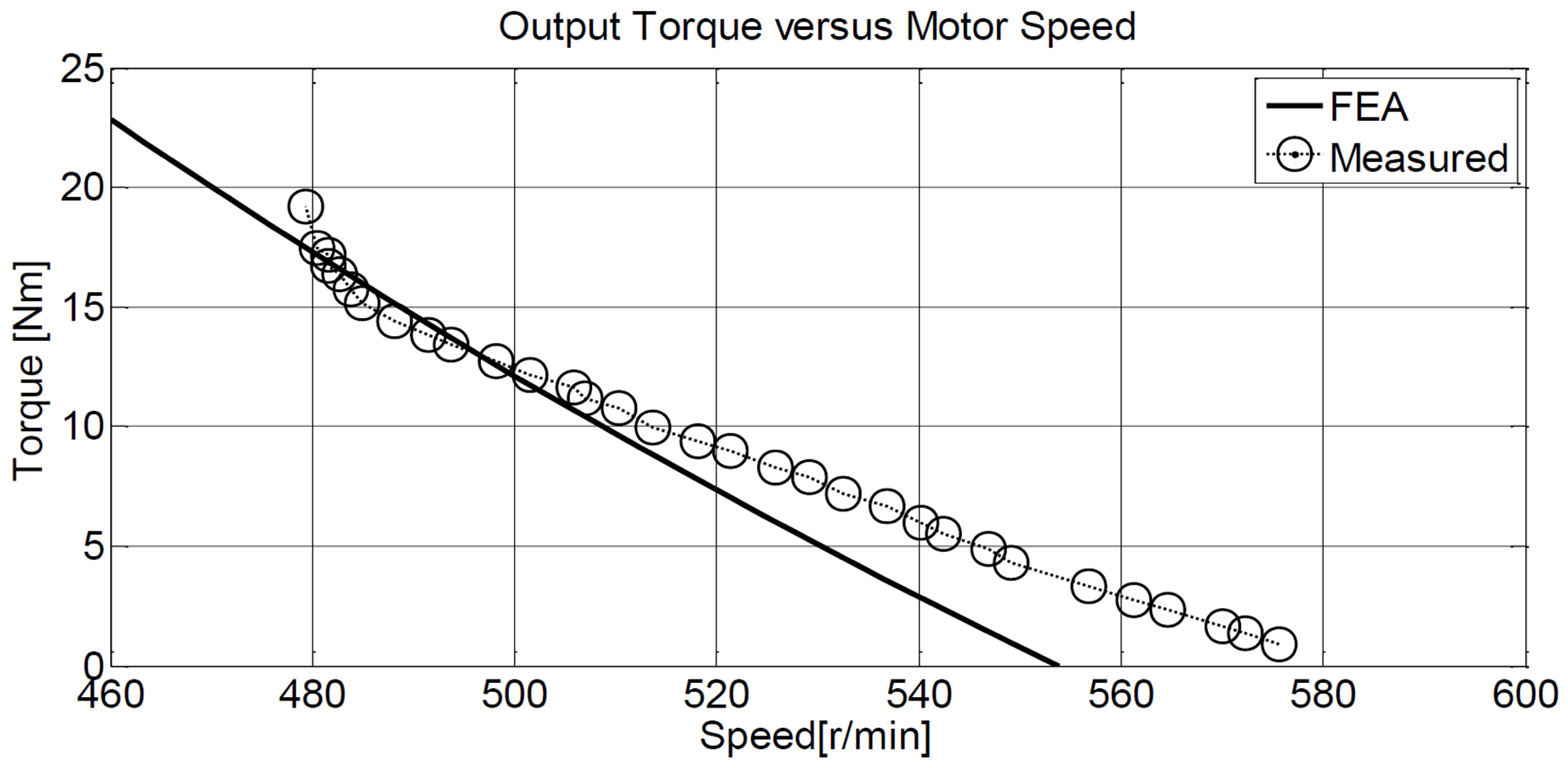
The field weakening control is implemented by considering two different operation regions: first, a conventional control for below base-speed and, second, a phase-advanced control for constant power region [25,26]. The operation region is defined by using an function which reflects the speed information according to reference speed, , and rated speed, , values. Up to the base speed, the motor speed is controlled by adjusting PWM according to the controller output. In this situation, the phase current is in phase with an allegedly flat portion of back-emf, which is assumed an interval duration of . The captured waveform of the phase current is presented in Figure 12 for the constant torque operation region. As can be seen in Figure 12, the phase current flows through a high inductance winding. The measured efficiency and torque-speed characteristics of the motor in the constant torque region are illustrated in Figure 13 and Figure 14, respectively. The analyses and tested results are in agreement.
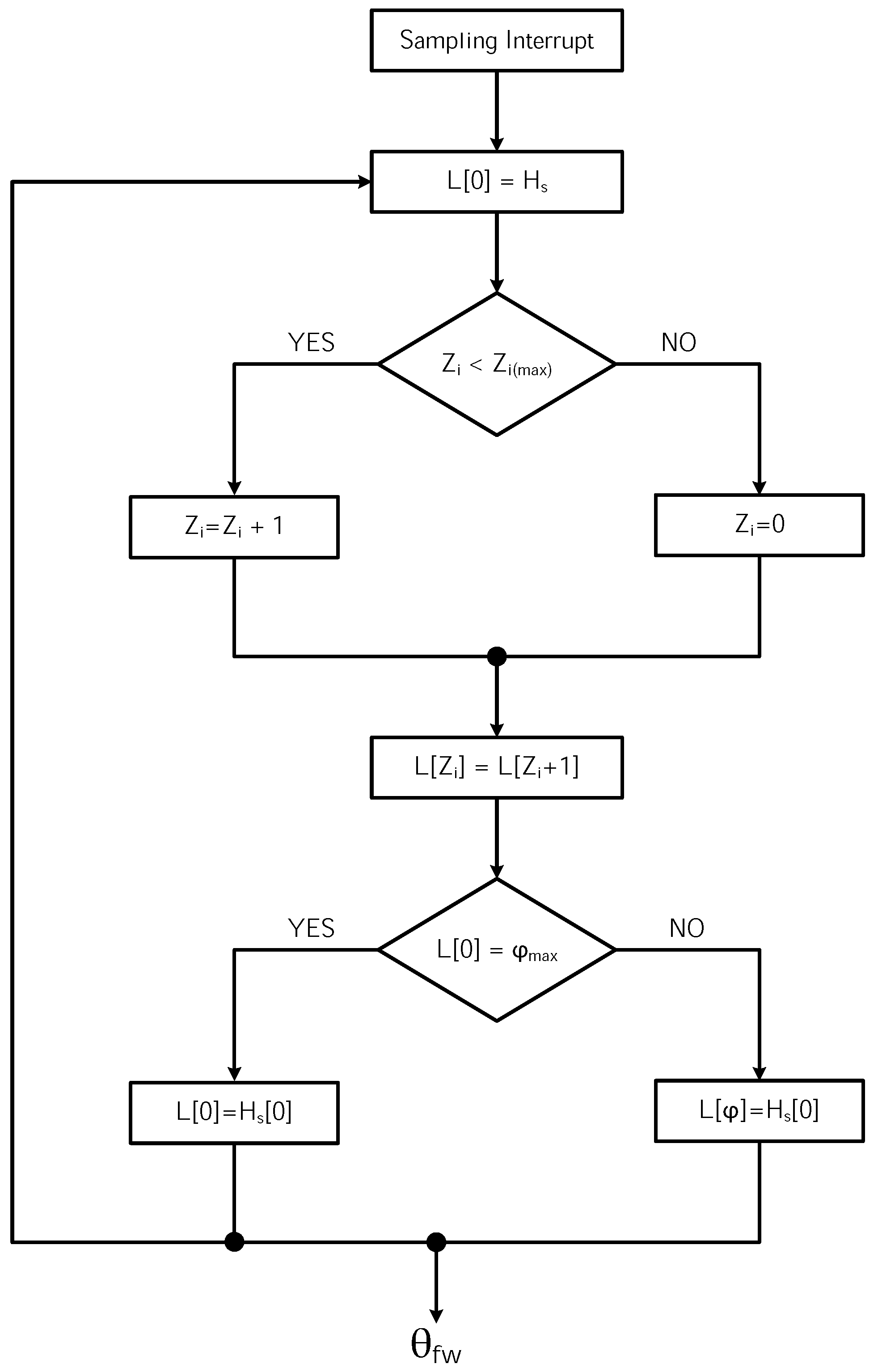
When the electric machine reaches its constant power region, the advance in phase current causes a current leap because of the lack of back-emf. This situation is the essence of field weakening operation: The current will decay slowly due to the higher valued phase inductance, and the back-emf will exceed the terminal voltage. If the value is chosen in the field weakening operation region, the shifting angle, i.e., time shift, is obtained by using the algorithm given in Figure A2. The real hall signals and the actual hall sensor data representing the aimed speed are used as inputs of the algorithm. The output of the algorithm is a set of virtual hall sensor signals which provide the advanced commutation. This task is accomplished by using a look-up table with the relation of speed and angle. After this operation, the hall signals are shifted, as (360 − ) the new virtual hall signals are transmitted to the switching logic circuit [14]. A subroutine to update the process is given in Equation (7).
where n is a factor which defines the ratio between the electrical period and the loop period of the sub-routine. is a conversion ratio carrying the information of new virtual hall signals. Additionally, and are the shifted hall signal angle information and the actual hall signal information, respectively. The real hall signals are stored in a vector presented in Equation (8) in order to create the virtual hall signals. The vector must be at least in an n-dimension. The real hall signals, , are assigned to the shifted indices, , as illustrated in the vector according to the variation of and . Moreover, as mentioned before, over-currents are highly possible due to the lack of a sufficient back-emf value at advanced angle switching. Thus, the current must be checked continuously to overcome any problem due to the over-current operation.
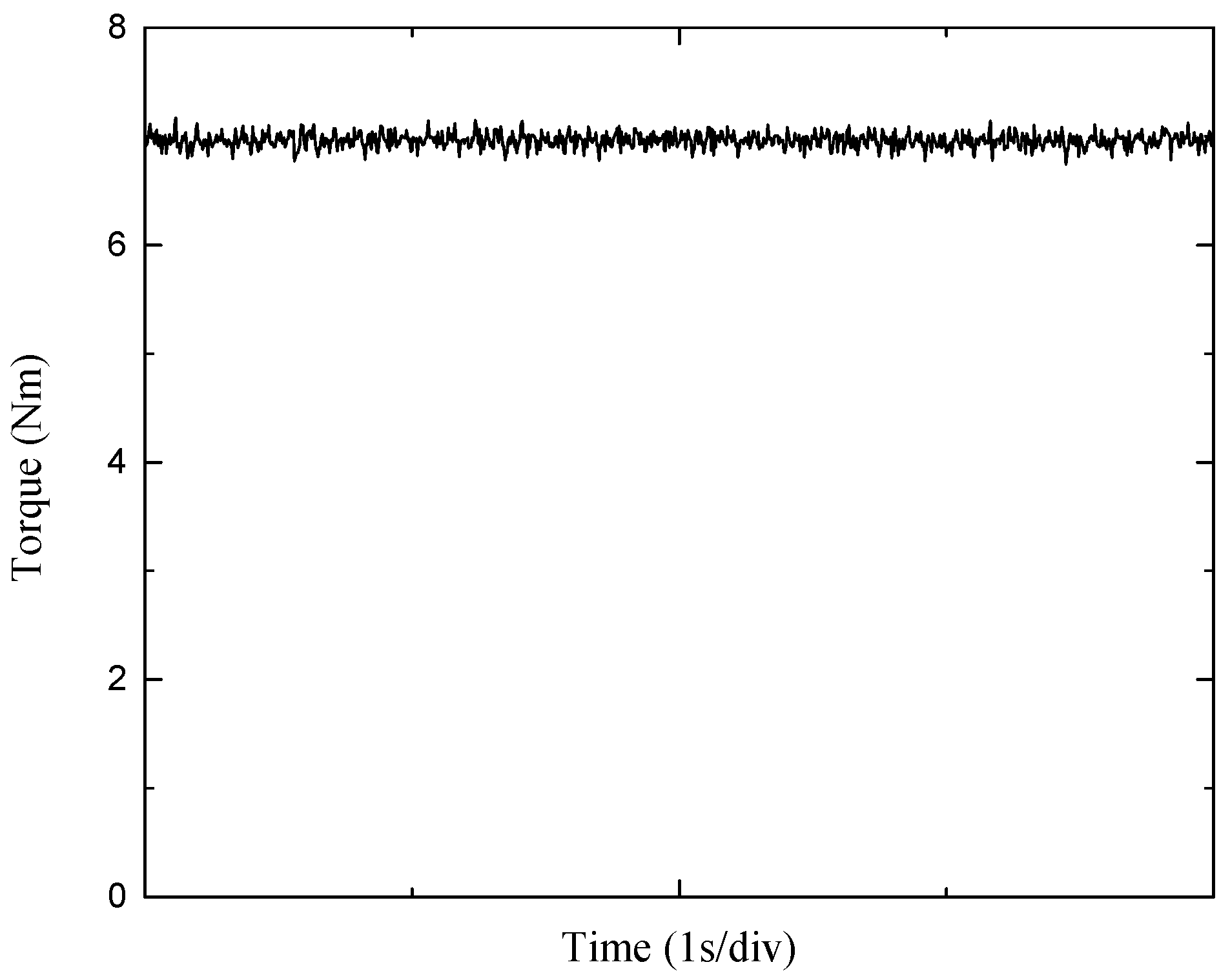
In Figure 15, the hall signal, phase current, and back-emf waveforms are given for the speed of 1012 min and the shaft torque of 5 N·m, whose waveform is shown in Figure 16. The current starts with a leap because of the low back-emf, and it decays slowly because of the high inductance. This slow decay causes an increased back-emf due to the negative current change rate. Thus, the fundamental idea underlying the field weakening operation of the BLDC motor can be comprehended via this figure. Similar results are given in Figure 17. The hall signal and phase current waveforms are given for the speed of 960 min and the shaft torque of 7 N·m, whose waveform is shown in Figure 18, while the phase-advanced angle is 25. As the advanced angle increases the speed of motor, the shaft torque is decreased to satisfy the constant power value. A nonlinear relation is observed between the speed and the angle as is expected. After 20 of phase-advanced angle, the speed is increased dramatically. At the value of 30, the motor has reached a 1047 min speed under the loading of 9 N·m. The maximum speed obtained is 1624 min at the loading of 4 N·m and with 60.
4. Discussion
The results show that there are some essential limitations in the field weakening control of SMPM BLDC motors. As can be seen, the difference of current waveforms given in Figure 15 and Figure 17 shows the effect of the phase-advanced current drive, which causes a high start-up current. These current pulses are somewhat limited by phase inductance. Another limitation is that a substantially high value of phase inductance is not applicable by considering the limitations of the electric motor structure and materials. Another important diminishing factor is the circulating current which occurs as a bumping current waveform. These current lumps deteriorate the field weakening operation and cause very high RMS currents, which are increased by ascending values of phase angles. As can be seen in Figure 19, the CPSR value, a critical criterion for EV propulsion applications, is smaller than those of IPMSM and induction motors.
The findings also uncover the features of unequal tooth structure: a low contribution to winding inductance improvement and, on the other hand, an enhanced torque production resulting from an inherent high winding factor. The experimental results show an adequate motor design that allows for higher winding inductance. However, it is also revealed that the field weakening capability of SMPM BLDC motors has certain limits. In Figure 20, the field weakening performance of an industrial BLDC motor with relatively lower winding inductance is shown. As can be seen, the current is decayed quickly after the advanced commutation due to a lower inductance. If the advanced angle is increased, it causes an abrupt current jump which is dangerous for semiconductor devices and winding heating. Moreover, the similar advanced angle method is implemented in [18]. In that study, the authors achieved a CPSR value of 2.94. The CPSR value is limited by the low winding inductance and the current is almost decayed to zero at the end of the 60 commutation interval. This performance shows the importance of higher winding inductance that can be achieved by a sub-fractional concentrated winding design.
For the studied motor, the obtained CPSR value after the performance tests was found to be 3.24, which shows slight incompetence for this type of motor. For electrical vehicle applications, these motors can function in limited speed-light electric vehicles such as electric scooters and e-tricycles rather than conventional electric passenger cars. Some studies which show optimistic results rely on theoretical bases. However, these results show limited performance.
5. Conclusions
The presented study includes the design, analysis, and experimental work of a sub-fractional slot-concentrated winding BLDC motor with higher winding inductance. The designed SMPM motor possesses unequal rectangular tooth widths, which infer easy manufacturing and enhanced torque production. The object of the study is to develop a BLDC motor design that contributes to drive performance, i.e., field weakening control. This contribution is yielded by the implementation of inductance value of higher stator windings. For a given motor topology, the higher winding inductance can be accomplished by using an alternate teeth-wound sub-fractional slot-concentrated winding structure. The value of winding inductance was calculated by FEA, and an experimental measurement was performed. The test results verify the intended design study. The implemented field weakening control strategy is presented in detail. The results of the experimental study on field weakening operations provide some important clues for the driving range of the designed motor. Considering all of the increased prospects from drive systems, the controller design effort is tightly correlated to the electric motor design.
Author Contributions
O.U. conceived of the idea of the research, participated to all study phases, and provided guidance and supervision. O.C.K. developed software and wrote the original draft preparation; S.S. performed FEM analysis; B.F. developed software. All authors have contributed significantly to this work.
Funding
This research received no external funding.
Conflicts of Interest
The authors declare no conflict of interest.
Appendix A
Figure A1.
Design methodology flowchart.

Figure A2.
Proposed field weakening algorithm.


Table A1.
Specifications and parameters of the manufactured BLDC motor.
| Parameters | Value |
|---|---|
| Rated Power | 1 (kW) |
| Rotor Length | 40 (mm) |
| Rated Voltage | 24 (V) |
| Outer Diameter | 180.5 (mm) |
| Rated Speed | 500 (min) |
| Winding Factor of the Stator | 0.965 |
| Fill Factor of the Stator | 65.94 (%) |
| d-axis Inductance | 98.41 ( + ) (H) |
Table A2.
Material Description.
| Part of BLDC Motor | Material |
|---|---|
| Rotor Yoke | Stell 1010 |
| Magnets | NdFe35 |
| Stator | M36-29G |
| Coils | Copper |
| Inner and Outer Regions | Vacuum |
References
- He, C.; Wu, T. Permanent magnet brushless DC motor and mechanical structure design for the electric impact wrench system. Energies 2018, 11, 1360. [Google Scholar] [CrossRef]
- Jahns, T.M. Flux-weakening regime operation of an interior permanent-magnet synchronous motor drive. IEEE Trans. Ind. App. 1987, IA-23, 681–689. [Google Scholar] [CrossRef]
- Schiferl, R.; Lipo, T.A. Power Capability of Salient Pole Permanent Magnet Synchronous Motors in Variable Speed Drive Applications. In Proceedings of the Industry Applications Society Annual Meeting, Pittsburgh, PA, USA, 2–7 October 1988. [Google Scholar]
- Patil, N.A.; Lawler, J.S.; McKeever, J.W. Determining Constant Power Speed Ratio of the Induction Motor from Equivalent Circuit Parameters. In Proceedings of the IEEE SoutheastCon, Huntsville, AL, USA, 3–6 April 2008. [Google Scholar]
- Senol, S.; Ustun, O. Study on a BLDC Motor Having Higher Winding Inductance: A Key to Field Weakening. In Proceedings of the XXth International Conference on Electrical Machines (ICEM), Marseille, France, 2–5 September 2012. [Google Scholar]
- Chaithongsuk, S. Optimal design of permanent magnet motors to improve field-weakening performances in variable speed drives. IEEE Trans. Ind. Electron. 2012, 59, 2484–2494. [Google Scholar] [CrossRef]
- Kong, H.; Cui, G.; Zheng, A. Field-Weakening Speed Extension of BLDCM Based on Instantaneous Theory. In Proceedings of the International Conference on Electrical and Control Engineering, Wuhan, China, 25–27 June 2010. [Google Scholar]
- Jung, S.; Mi, C.C.; Nam, K. Torque control of IPMSM in the field-weakening region with improved DC-link voltage utilization. IEEE Trans. Ind. Electron. 2015, 62, 3380–3387. [Google Scholar] [CrossRef]
- Junlong, L.; Yongxiang, X.; Jibin, Z.; Baochao, W.; Qian, W.; Weiyan, L. Analysis and design of SPM machines with fractional slot concentrated windings for a given constant power region. IEEE Trans. Magn. 2015, 51, 1118–1125. [Google Scholar] [CrossRef]
- Hanselman, D.C. Brushless Permanent Magnet Motor Design, 2nd ed.; The Writers’ Collective: Columbus, OH, USA, 2003; ISBN 978-1932133639. [Google Scholar]
- El-Refaie, A.M.; Jahns, T.M.; Novotny, D. Analysis of surface permanent magnet machines with fractional-slot concentrated windings. IEEE Trans. Energy Convers. 2006, 21, 34–43. [Google Scholar] [CrossRef]
- Cros, J.; Viarouge, P. Synthesis of high performance PM motors with concentrated windings. IEEE Trans. Energy Convers. 2002, 17, 248–253. [Google Scholar] [CrossRef]
- Soong, W.L.; Miller, T. Field-weakening performance of brushless synchronous AC motor drives. IEE Proc. Electr. Power Appl. 1994, 141, 331–340. [Google Scholar] [CrossRef]
- Dorrell, D.G. A Review of the design issues and techniques for radial-flux brushless surface and internal rare-earth permanent-magnet motors. IEEE Trans. Ind. Electron. 2011, 58, 3741–3757. [Google Scholar] [CrossRef]
- Chan, C.C.; Jiang, J.Z.; Xia, W.; Chan, K.T. Novel wide range speed control of permanent magnet brushless motor drives. IEEE Trans. Pow. Electron. 1995, 10, 539–546. [Google Scholar] [CrossRef] [Green Version]
- Bianchi, N.; Bolognani, S.; Chalmers, B.J. Salient-rotor PM synchronous motors for an extended flux-weakening operation range. IEEE Trans. Ind. Electron. 2000, 36, 1118–1125. [Google Scholar] [CrossRef]
- Miti, G.K.; Renfrew, A.C.; Chalmers, B.J. Field-weakening regime for brushless DC motors based on instantaneous power theory. IEE Proc. Electr. Power Appl. 2001, 148, 265–271. [Google Scholar] [CrossRef]
- Yang, Y.; Ting, Y. Improved angular displacement estimation based on hall-effect sensors for driving a brushless permanent-magnet motor. IEEE Trans. Ind. 2014, 61, 504–511. [Google Scholar] [CrossRef]
- Hemmati, S.; Lipo, T.A. Field Weakening of a Surface-Mounted Permanent Magnet Motor by Winding Switching. In Proceedings of the International Symposium on Power Electronics Power Electronics, Electrical Drives, Automation and Motion, Sorrento, Italy, 20–22 June 2012. [Google Scholar]
- El-Refaie, A.M.; Zhu, Z.Q.; Jahns, T.M.; Howe, D. Winding Inductances of Fractional Slot Surface-Mounted Permanent Magnet Brushless Machines. In Proceedings of the Industry Applications Society Annual Meeting IAS’08, Edmonton, AB, Canada, 5–9 October 2008. [Google Scholar]
- Soong, W.; Ertugrul, N. Field-weakening performance of interior permanent-magnet motors. IEEE Trans. Ind. Appl. 2002, 38, 1251–1258. [Google Scholar] [CrossRef] [Green Version]
- Li, G.J.; Zhu, Z.Q. Analytical modeling of modular and unequal tooth width surface-mounted permanent magnet machines. IEEE Trans. Magn. 2015, 51, 8107709. [Google Scholar] [CrossRef]
- Ishak, D.; Zhu, Z.; Howe, D. Permanent Magnet Brushless Machines With Unequal Tooth Widths and Similar Slot and Pole Numbers. In Proceedings of the 39th IAS Annual Meeting Industry Applications Conference, Seattle, WA, USA, 3–7 October 2004. [Google Scholar]
- Ishak, D.; Zhu, Z.; Howe, D. Comparison of PM brushless motors, having either all teeth or alternate teeth wound. IEEE Trans. Energy Convers. 2006, 21, 95–103. [Google Scholar] [CrossRef]
- Lawler, J.; Bailey, J.M.; McKeever, J.W.; Pinto, J. Extending the constant power speed range of the brushless DC motor through dual-mode inverter control. IEEE Trans. Power Electron. 2004, 19, 783–793. [Google Scholar] [CrossRef]
- Rong, L.; Weiguo, L. A Novel PM BLDC Motors Inverter Topology for Extending Constant Power Region. In Proceedings of the 33rd Annual Conference of the IEEE Industrial Electronics Society, Taipei, Taiwan, 5–8 November 2007. [Google Scholar]
Figure 1.
Current limit circle and characteristic current.

Figure 2.
The demonstration of stator slots with alternate teeth winding and all teeth winding configuration.
Figure 2.
The demonstration of stator slots with alternate teeth winding and all teeth winding configuration.

Figure 3.
(a) Equal teeth, (b) rectangular shaped unequal teeth, (c) unequal teeth windings with pole shoe.
Figure 3.
(a) Equal teeth, (b) rectangular shaped unequal teeth, (c) unequal teeth windings with pole shoe.

Figure 4.
Finite element analysis back-emf waveforms for Figure 3 designs.
Figure 4.
Finite element analysis back-emf waveforms for Figure 3 designs.

Figure 5.
Adaptive mesh plot for magnetostatic analysis.

Figure 6.
3D model of the 1 kW 24/20 slot–pole machine.

Figure 7.
Magnetic flux lines of unequal teeth stator with rectangular shaped stator poles.

Figure 8.
Manufacture of a 1 kW 24/20 slot–pole surface mounted permanent magnet (SMPM) motor.

Figure 9.
Experimental test-bed: prototype 24/20 slot–pole BLDC motor coupled to generator.

Figure 10.
Experimental test-bed: inverter, DSP control unit and torque transducer.

Figure 11.
Overall block diagram of the proposed BLDC motor drive in the field weakening operation.

Figure 12.
Constant torque region experimental results: motor phase current waveform (10 A/div, 2 ms/div).
Figure 12.
Constant torque region experimental results: motor phase current waveform (10 A/div, 2 ms/div).

Figure 13.
Efficiency versus motor speed.

Figure 14.
Output torque versus motor speed.

Figure 15.
Phase–a current and hall–a signal under 5 N·m load with 25 reference delay angle.

Figure 16.
Torque response under 5 N·m load with 25.

Figure 17.
Phase–a current and hall–a signal under 7 N·m load with 25 reference delay angle.

Figure 18.
Torque response under 7 N·m load with 25.

Figure 19.
Output torque versus motor speed for different advanced angles.

Figure 20.
Phase–a current and hall–a signal under 5 N·m load with 10 reference delay angle.

© 2018 by the authors. Licensee MDPI, Basel, Switzerland. This article is an open access article distributed under the terms and conditions of the Creative Commons Attribution (CC BY) license (http://creativecommons.org/licenses/by/4.0/).
Share and Cite
MDPI and ACS Style
Ustun, O.; Kivanc, O.C.; Senol, S.; Fincan, B. On Field Weakening Performance of a Brushless Direct Current Motor with Higher Winding Inductance: Why Does Design Matter? Energies 2018, 11, 3119. https://doi.org/10.3390/en11113119
AMA Style
Ustun O, Kivanc OC, Senol S, Fincan B. On Field Weakening Performance of a Brushless Direct Current Motor with Higher Winding Inductance: Why Does Design Matter? Energies. 2018; 11(11):3119. https://doi.org/10.3390/en11113119
Chicago/Turabian StyleUstun, Ozgur, Omer Cihan Kivanc, Seray Senol, and Bekir Fincan. 2018. "On Field Weakening Performance of a Brushless Direct Current Motor with Higher Winding Inductance: Why Does Design Matter?" Energies 11, no. 11: 3119. https://doi.org/10.3390/en11113119
Note that from the first issue of 2016, this journal uses article numbers instead of page numbers. See further details here.