Node Mapping Criterion for Highly Saturated Interior PMSMs Using Magnetic Reluctance Network
by
 , ,
, ,
Damian Caballero
1,2,* ,
,
Borja Prieto
1,2,
Gurutz Artetxe
1,2,
Ibon Elosegui
1,2 and
Miguel Martinez-Iturralde
1,2 1
Ceit, Manuel Lardizabal 15, 20018 Donostia/San Sebastian, Spain
2
Universidad de Navarra, Tecnun, Manuel Lardizabal 13, 20018 Donostia/San Sebastian, Spain
*
Author to whom correspondence should be addressed.
Energies 2018, 11(9), 2294; https://doi.org/10.3390/en11092294
Submission received: 19 July 2018
/
Revised: 24 August 2018
/
Accepted: 27 August 2018
/
Published: 31 August 2018
(This article belongs to the Special Issue Permanent Magnet Synchronous Machines)
Abstract
:Interior Permanent Magnet Synchronous Machine (IPMSM) are high torque density machines that usually work under heavy load conditions, becoming magnetically saturated. To obtain properly their performance, this paper presents a node mapping criterion that ensure accurate results when calculating the performance of a highly saturated IPMSM via a novel magnetic reluctance network approach. For this purpose, a Magnetic Circuit Model (MCM) with variable discretization levels for the different geometrical domains is developed. The proposed MCM caters to V-shaped IPMSMs with variable magnet depth and angle between magnets. Its structure allows static and dynamic time stepping simulations to be performed by taking into account complex phenomena such as magnetic saturation, cross-coupling saturation effect and stator slotting effect. The results of the proposed model are compared to those obtained by Finite Element Method (FEM) for a number of IPMSMs obtaining excellent results. Finally, its accuracy is validated comparing the calculated performance with experimental results on a real prototype.
1. Introduction
The demand for Permanent Magnet Synchronous Machines (PMSM) is rapidly increasing in high-performance applications, such as electric vehicles [1,2,3,4], due to their high power density. In particular, the configuration of buried magnets inside the rotor is becoming very popular, because of the additional torque made available to saliency, their wide constant power speed region, and their high demagnetization withstand capability, among others [5,6].
The design process of a PMSM frequently involves the aid of software based on Finite Elements Methods (FEM) [7,8,9,10,11,12,13]. Although accuracy of the results is very high, it requires a high computational cost, together with an elevated amount of time to define the problem. This makes FEM more suitable for validation purposes rather than for preliminary machine design by iterative process. Consequently, the use of analytical design tools that rely on magnetic circuits instead of FEM is becoming widespread.
Different authors have presented simple magnetic circuits for different PMSM topologies [14,15,16]. The results are acceptable as a first estimation of the machine performance, but they are not comprehensive enough if a transient analysis or a deeper study is required. For this purpose, complex magnetic circuit models based on magnetic reluctance network, known as Magnetic Circuit Model (MCM), have been proposed [17]. The methodology is very similar to simple magnetic equivalent circuits; the main difference lies in the larger number of elements that the machine’s geometry is discretized.
In the literature, different MCMs have been proposed [18,19,20,21,22,23]. However, a clear meshing criterion that guarantees accurate results regardless of the size or geometry of the machine, i.e., a node mapping criterion for different machine regions, is not provided. In general, the reluctance element’s distribution is set according to the main flux paths [20,24]. However, in machines that work at heavy load conditions, the flux paths are in most cases unpredictable, especially in IPMSMs, where the complex geometry of the rotor makes difficult their analytical modelling [8,25,26]. In addition, the fact that the magnetic flux can only pass through an element in a unique defined direction makes it advisable to establish a general node mapping criteria for IPMSMs.
In this paper, a general node mapping criterion for IPMSMs of any geometry and size is presented. To that end, MCM with variable discretization levels for the different geometric domains is developed. The proposed MCM models V-shaped IPMSMs, with variable magnet depth and angle between magnets. A suitable MCM structure composed of generic cells, named nodal elements, as modelling element for any part of the machine is proposed. The nodal elements contain geometric and electromagnetic information of the modelled physical domain. The model contemplates rotor motion, allowing dynamic analysis, i.e., time stepping simulations. The MCM takes into account the effects of stator slotting, the airgap magnetomotive force (MMF) waveform due to armature current, and cross-magnetizing saturation effects due to an improved magnetic flux path definition. This, in turn, leads to more accurate results than other simpler magnetic circuit models shown in the bibliography.
This paper is organized as follows. First, the MCM developed for IPMSMs is described. Next, the magnetic phase flux linkage at heavy load conditions for different V-shaped IPMSMs is calculated. Then, an analysis of the accuracy of the results from using different node mappings in the MCM is conducted, and the results are compared to those obtained by the FEM software. This analysis provides a node mapping criterion to ensure sufficient accuracy when calculating the performance of an IPMSM with a magnetic reluctance network. Finally, once the node mapping criterion is described, the presented methodology is validated by comparing the calculated performance to tests on a real traction IPMSM working under heavy load conditions.
2. Definition of the Magnetic Circuit Model
In this section, the MCM developed for IPMSM is described. The MCM allows the number of nodes the machine is discretized into to be selected. The proposed MCM is divided into three regions: stator, rotor and airgap. A generic nodal element, shown in Figure 1, is proposed.
The node is set in the center of the nodal element. Each nodal element has its own coordinates (i,j), so it may be stored in a nodal elements matrix. Appropriate row and column are assigned to each nodal element according to its location on the associated discretized geometrical domain being modelled. Information regarding the associated geometry (identifier, row, column, region, position, etc.) is stored as well. Each nodal element has four sub-elements that capture both the radial and orthoradial magnetic fluxes and, therefore, possible cross-coupling effects [27,28]. The sub-element geometrical domain can be rectangular, trapezoidal or even triangular. Sub-element information that is held is fundamental for the solving process: orientation length L, transversal section , permeance, permeability , MMF source, etc. Magnetic permeance, , is employed for convenience in the solving process; it is the inverse of magnetic reluctance, , which is calculated by Equation (1) [29].
To reduce the computational effort, if periodicities exist within the machine, just part of it is modelled. The number of periodicities is obtained according the number of pole pairs and slots (Equation (2)).
where is the number of stator slots, p the number of pole pairs and GCD stands for Greatest Common Divisor.
The geometric positioning of the nodal elements that model different regions of the machine, is established according to the existing main magnetic flux paths. In addition, it facilitates the connection between nodal elements, and therefore, the different regions of the machine can be accurately meshed.
2.1. Stator
The stator yoke, slots, slot-openings, teeth, and tooth-tip are modelled separately. The MCM parameters that define the stator node mapping are presented in Table 1. As an illustrative example, the values given in the table result in the node mapping shown in Figure 2.
Presented parameters in Table 1 define the number of node columns and rows in stator regions, as can be observed in Figure 2. For open slot machines, is null. The armature current MMF sources are located at the north and south sub-elements of each element belonging to the teeth and are calculated by Equation (3).
where is the winding sequence matrix that relates the teeth wound by each coil to the corresponding phase winding [30]. is the phase current vector. is the number of turns per slot and layer. Finally, is the number of parallel connected winding groups.
2.2. Rotor
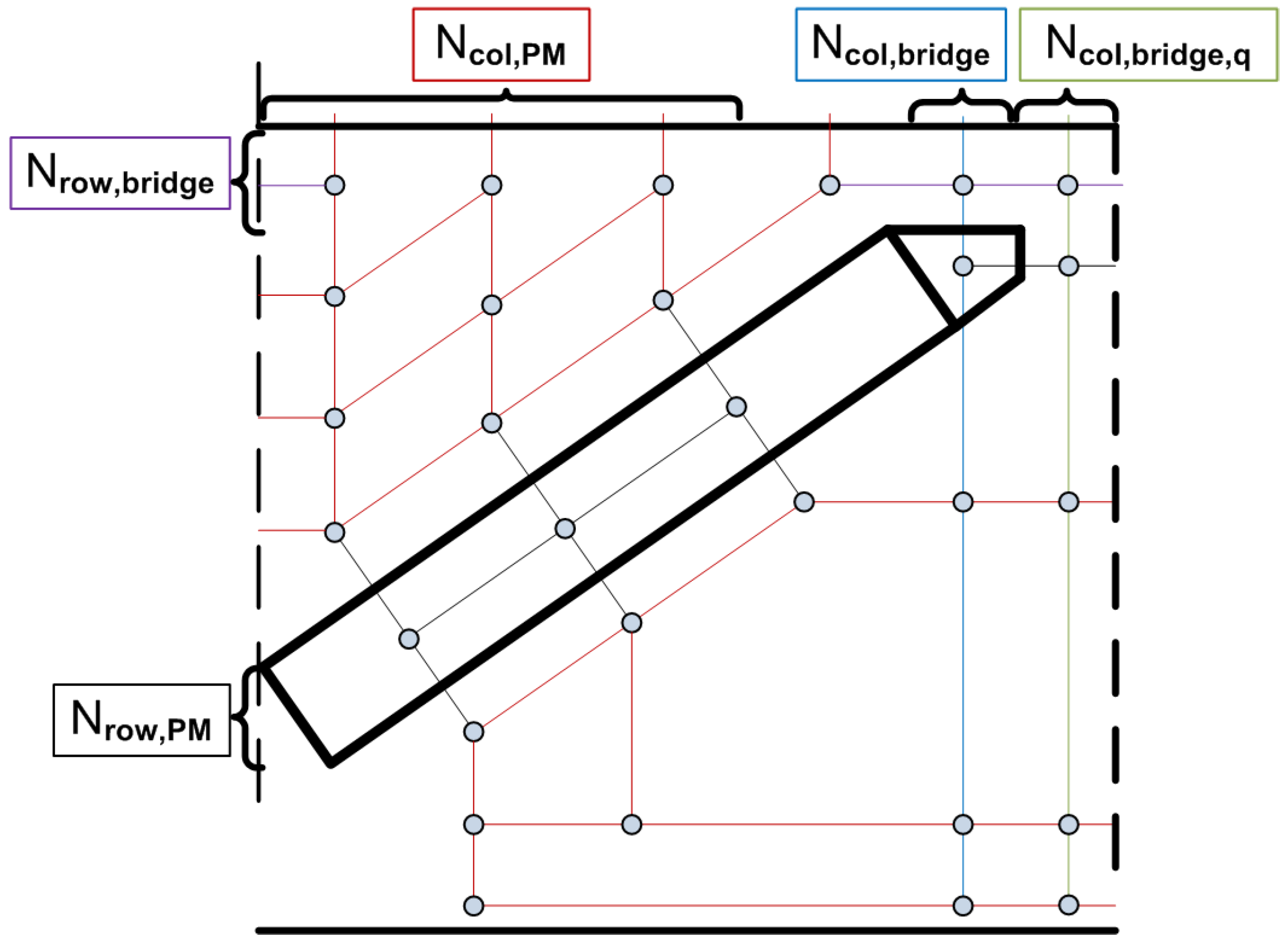
The parameters that define the reluctance network for IPMSM rotors are presented in Table 2. Due to the existing symmetry, only the mapping for half a pole needs to be defined. To ease the comprehension, the values given in the table result in the node mapping shown in Figure 3.
In Figure 4, the whole pole node mapping scheme for V-shaped IPMSMs is shown.
Regarding the rotor nodal mapping, some nuances must be taken into consideration:
- also define the number of node rows in the non-magnetic material and in the q-axis magnetic bridge.
- :
- -
- It defines rotor yoke’s node mapping: over and below PM side. These node distributions are “triangular”, with columns and as we move away from d-axis, the number of rows decreases from to one.
- -
- It defines with other parameters as and and one necessary extra node (for node connection purposes), the number of columns in the upper rotor nodal rows, belonging to an arc whose thickness is the bridge height.
It is remarkable that the same nodal mapping defined by Table 2 may be established for extreme cases of IPMSM. As an example, V-shaped in Figure 5 and embedded in Figure 6 are shown.
The magnets, the rotor yoke, the magnetic bridge and the rotor slot non-magnetic material, which is responsible for preventing a large magnetic flux leakage, are modelled by a selectable number of elements. The MMF contribution is computed by Equation (4) and assigned to the north and south sub-elements corresponding to permanent magnets.
is the magnet height, and the coercive field strength.
2.3. Airgap
This region is the most significant part of the MCM and the overall precision of the model depends on its modelling. Moreover, it is the link between the stator and rotor models, thus a correct modelling of the airgap is necessary. Therefore, the airgap model is built by taking into account the relative position between the stator and the rotor. Since machine rotation is considered, airgap node mapping is varied for each time step. An airgap element is placed at the same angular position of each stator and rotor nodal element in contact with the airgap, as shown in Figure 7. It is important to note that more finely discretized stator and/or rotor models entail a more detailed airgap region node mapping.
The number of airgap row elements is determined by the parameter . In Figure 7, the proposed airgap node mapping is visually displayed for a equal to 2.
To link the airgap with stator and rotor entities, auxiliary nodes are placed in the airgap region boundaries, as shown in Figure 7 with small yellow circles. They only have north and south sub-elements, and an infinite permeance. Therefore, it is a mathematical element that is introduced in the circuit matrix system. Its necessity is due to the inter-entities borders, where the airgap sub-elements are connected to the nearest auxiliary node (Figure 8). If they are connected simultaneously to various airgap nodes, the existence of these auxiliary nodes guarantees that each nodal element belonging to any machine entity is connected to other nodes by no more than four sub-elements. Thus, it is possible to generate the flux and permeanace matrix, according to the defined nodal element structure (Figure 1).
2.4. Solving Process
Once all the nodes are linked and the branches defined, the MCM is completely set. Owing to the non-linear magnetic behavior of the stator and rotor materials, whose B-H curve are imported from materials database and used as a lookup table, the MCM needs to be solved iteratively. Firstly, permeance and magnetic source flux matrices, and , are calculated for each sub-element. The matrix circuit is solved in terms of Kirchoff’s Voltage Law (KVL), and the scalar magnetic potential at each node is obtained by:
The magnetic flux that crosses each corresponding branch from node i to node j is calculated by:
where MMF is the addition of different MMF sources at each branch. A weighted average of the updated and previous iteration magnetic permeability is used in the following iteration step by the corresponding permeance sub-element, rewriting data in and recalculating Equations (5) and (6) [20].
The iteration process is finished when the following convergence criterion is met:
where is the committed mean error in sub-element permeability at iteration k.
2.5. Data Post-Processing
A key parameter for determining machine behavior is the phase magnetic flux linkage, [31]. The magnetic flux linked by each phase winding can be computed by Equation (8).
where is the number of symmetries which the problem has been divided due to the existing geometry periodicity, is the number of turns per slot and layer, and is the number of pole groups in parallel. The matrix is the magnetic flux that crosses each pair of slot-teeth. This is easily obtained once the MCM is solved.
Depending on whether the MCM is solved for a load operating point or at no-load condition, the phase magnetic flux linkage is denoted as and , respectively. Using Park’s transformation matrix, it is possible to work at d-q rotational reference system, whose main advantage is the fact that the different variables are time invariant. The electromagnetic torque is computed by Equation (9).
3. Results Using MCM with Different Node Mapping
The described MCM is implemented in MATLAB. To obtain a MCM node mapping criterion that guarantee an acceptable balance between results accuracy and computational costs, an analysis of the influence of the discretization level obtained by the model was conducted.
Furthermore, to assess the validity of the proposed MCM, three different size IPMSMs, whose characteristics are presented in Table 3, were evaluated.
The analysed machines have very different geometries to validate the proposed MCM and establish a node mapping criterion, regardless of the size of the machine.
The load conditions for each machine are presented in Table 4.
As Table 5 and Figure 9 illustrate, the three machines operate under heavy load conditions for the considered operating points. In the case of Motor C (Figure 9c), although the stator is not highly saturated, it can be observed that the armature current MMF is comparable to permanent magnet MMF, thereby establishing the magnetic axis almost in the q-axis. Besides, the machine comprises wide slots that behaves as barriers to the magnetic flux and, therefore, increasing the magnetic saturation at the rotor bridges. Altogether, this makes not only the magnetic flux paths more unpredictable but also the cross-coupling effect appreciable.
To establish a general node mapping criterion, the presented motor geometries have been evaluated with the aid of the developed MCM and the discretization level presented in Table 6. Each column defines a whole machine node mapping and is defined so that a specific machine’s modelled part is studied, i.e., in the case of Stator X, the node mapping parameters that define the stator are modified while the rest of parameters are kept at their lowest possible value. The parametric analysis carried out allows to separately analyse the influence of each model. The Xs in Table 6 refer to values that have been evaluated in each analysis, ranging from 1 to 6. For the parameter controlling the rotor discretization (Rotor X), the Xs values are evaluated in threes due to the complexity of the IPMSM rotor geometry and the difficulties to predict the magnetic flux paths at heavy load conditions.
As explained in Section 2.5, the key parameter to determine the machine performance is the magnetic flux linkage, . Thus, it is carried out a further analysis on this parameter obtaining.
In Table 7, results obtained by FEM are presented.
In Table 8, the relative errors between the results of the MCM and FEM are presented for the first and third time harmonics of the waveforms. Each row corresponds to results obtained when a MCM node mapping defined in Table 6 is employed with a determined X value. For example, Stator 1 means one value for all the stator parameters, and the other parameters are set to the default value.
In Figure 10, the error tendency for the first harmonic is graphically plotted.
The discrepancies between the results obtained by the MCM and the FEM are fairly low, especially taking into account the deep saturation of the iron parts for the considered operating points.
To show graphically the great accuracy obtained by the developed MCM, some important magnetic calculated characteristics are presented and compared with obtained by FEM simulation.
In Figure 11, the corresponding to Motor A is presented. Its time distribution at an electric cycle for a given stator phase is shown.
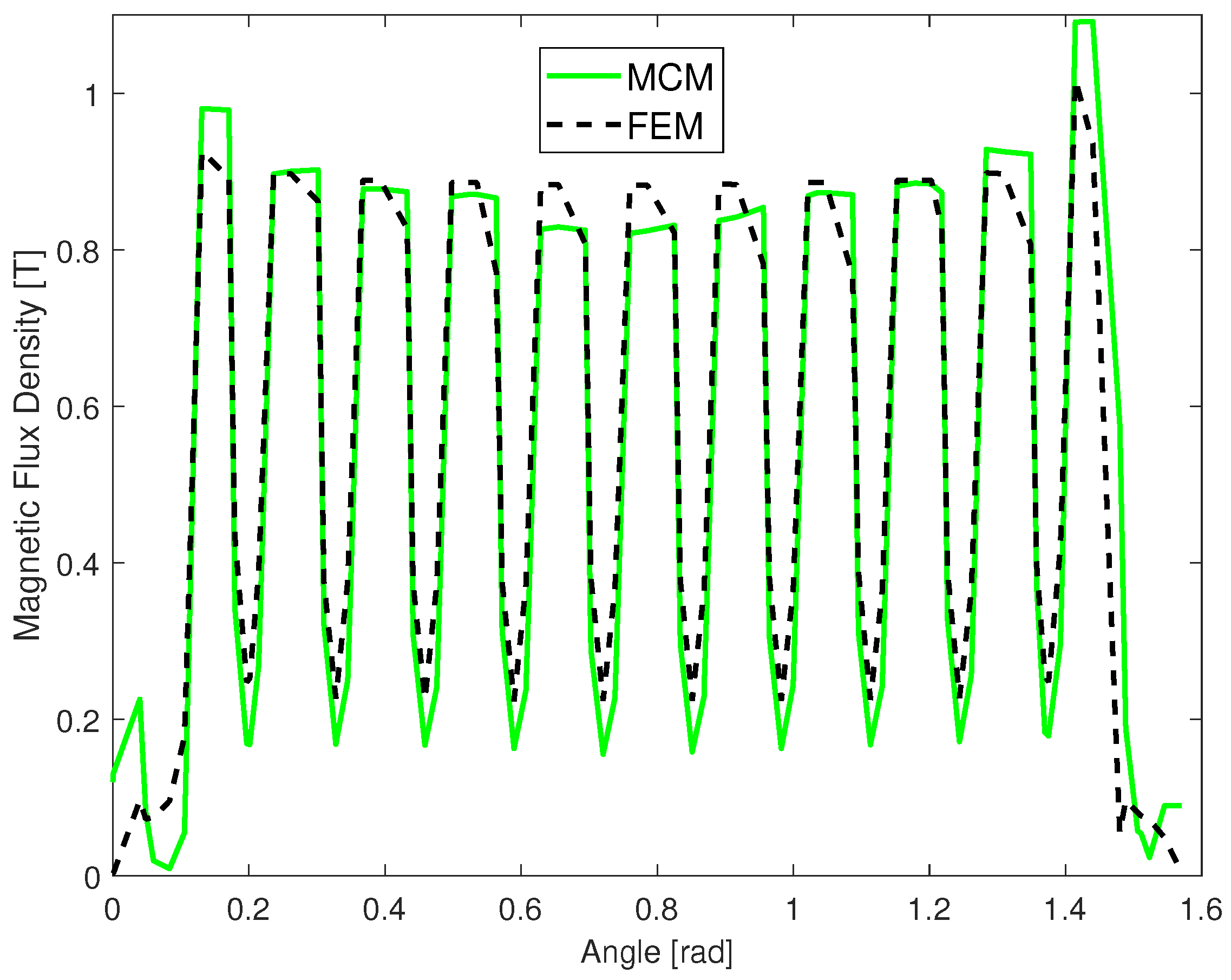
In Figure 12, the spatial distribution of airgap magnetic flux density along a pole for Motor A at no load operation point is shown. It reflects the accuracy obtained in terms of taking into account the slotting effect, noticing the well calculated magnetic flux density ripple, and also, in terms of the well calculated beginning and ending of the mentioned waveform, which means that the bridge’s model works correctly.
The MCM node mapping used is the one termed “”, due to the excellent results obtained.
4. Results Discussion and Node Mapping Criterion
When a machine is modelled by a magnetic reluctance network, it is usually not clear which node mapping configuration offers the optimal balance between accuracy and simulation time. With the aim of establishing a node mapping criterion, the results collected in Table 8 and plotted in Figure 10 are examined in greater detail in the following paragraphs:
Stator (Figure 10 a)
As can be observed, the higher is the number of stator nodal elements, the better is the accuracy of the results. The main reason is that, when the number of stator elements increases, so does the number of airgap elements.
Rotor (Figure 10 b)
Although the rotor has a considerable number of nodal elements, the stator is poorly meshed. This means that the linking between airgap and stator is not good enough, especially in terms of taking the slotting effect into account.
For Motor A and Motor B, the number of airgap nodes does not increase as much when is increased, unlike the case where the stator is more finely discretized. Nevertheless, for Motor C, the number of airgap nodes is significantly increased, because the number of slots per pole is low, and therefore the effect of stator discretization in the airgap meshing is lower.
Bridge (Figure 10 c)
Because of the high magnetic saturation in the bridge, the number of nodes does not affect the results.
Airgap (Figure 10 d)
The airgap meshing is controlled by the number of existing nodal elements at the stator–airgap border, and the rotor–airgap border. A different number of , does not involve a thorough whole machine physical domain modelling. Therefore, the obtained results are invariant.
Additionally, the computational time was measured for the different mapping configurations. In Figure 13, the normalized simulation time is displayed for Motor B using different node densities.
For the analysis called BridgeX, the defined MCM has a slightly higher computational cost due to the increasing number of deeply saturated permeance sub-elements. In addition, it should be noted that the high computational cost for the RotorX analysis is due to the fact that the number of rotor elements increases three times faster than parameter X.
The reflected data in Table 10 show the required computation time using FEM and MCM corresponding to Stator1 node mapping. The time data relate to one time step solving process.
It should be highlighted that the required computation time for solving MCM shown in Table 10 is up to seven times less than the required time for solving FEM. This together with the fact that, in contrast to FEM, MCM is instantaneously generated, makes our proposed MCM a suitable and fast designing tool.
Based on the accuracy of the results and the required solving time, it can be stated that a good node mapping choice is in the range of configurations to .
In Table 11, the airgap node mapping densities are presented for all three machine configurations under study. The information corresponds to a single airgap row. Various airgap node row details are given: number of nodes per pole pair, average distance between two consecutive nodes, and number of nodes per slot pitch.
Next, an analysis to obtain a general node mapping criterion was carried out.
- The number of nodes per pole pair is increased because of the higher value of X. Additionally, the difference between different geometries is due to the fact that the number of slots per pole are different, and the stator mapping is modelled for each slot-tooth pair. In this regard, setting a number of nodes per pole is not sufficient to establish a general node mapping criterion.
- The average distance between consecutive nodes depends on the number of airgap nodes and especially on the airgap diameter, i.e., motor size. As can be seen in Motor C, despite having very low values, it does not guarantee excellent results.
- The number of nodes per slot pitch for Motor A and Motor B with at least a value of 5 is sufficient for obtaining acceptable results. Nevertheless, when analysing rotor mappings, although this ratio is reached, the stator magnetic flux paths are not very well defined. In the case of Motor C, due to the lower number of nodes per pole pair, a value of at least 10 (Stator3) is needed. This value is also reached at rotor analysis, but, as explained previously, the stator node mapping is not very well defined.
The analysis presented here leads to the next node mapping criterion for modelling IPMSM by MCM.
- The key point is that the number of nodes per slot in the airgap must be at least seven.As stated in Table 8 and the airgap region nodal information in Table 11, specifically those displayed in the third column (defined with the heading Nodes per slot and pitch), the best results are obtained for MCM node mappings with a ratio value of at least seven nodes per slot in the airgap region.
- There must be at least three equidistant nodes in the stator slot and the tooth span.To consider the slotting effect and hence obtain accurate results, according to Table 8, the nodal configuration named Stator 3, that guaranties having at least three equidistant nodes in the stator slot and the tooth span, is enough.
- At least three rows of nodal elements show be employed at both rotor yokes.
By applying these criteria, an adequate connection between the stator and rotor models can be generated, leading to accurate results.
5. Experimental Validation
With the aim of validating the proposed methodology, a real traction motor with embedded magnets was tested. Its main characteristics are shown in Table 12.
The prototype machine has been previously simulated via FEM at rated load. In Figure 14, it can be appreciated that the motor is magnetically saturated, reaching more than 2 T at some points.
After applying the node mapping criteria, the main characteristics were obtained and compared with FEM simulations, as shown in Table 13. The operation point is set by defining the same current values for both numerical models.
The prototype performance was obtained by standard IEC testing in the test bench shown in Figure 15.
In Table 14, the experimental results at rated load conditions are presented.To allow for a fair comparison, the MCM was evaluated at an operating point corresponding to the rated power.
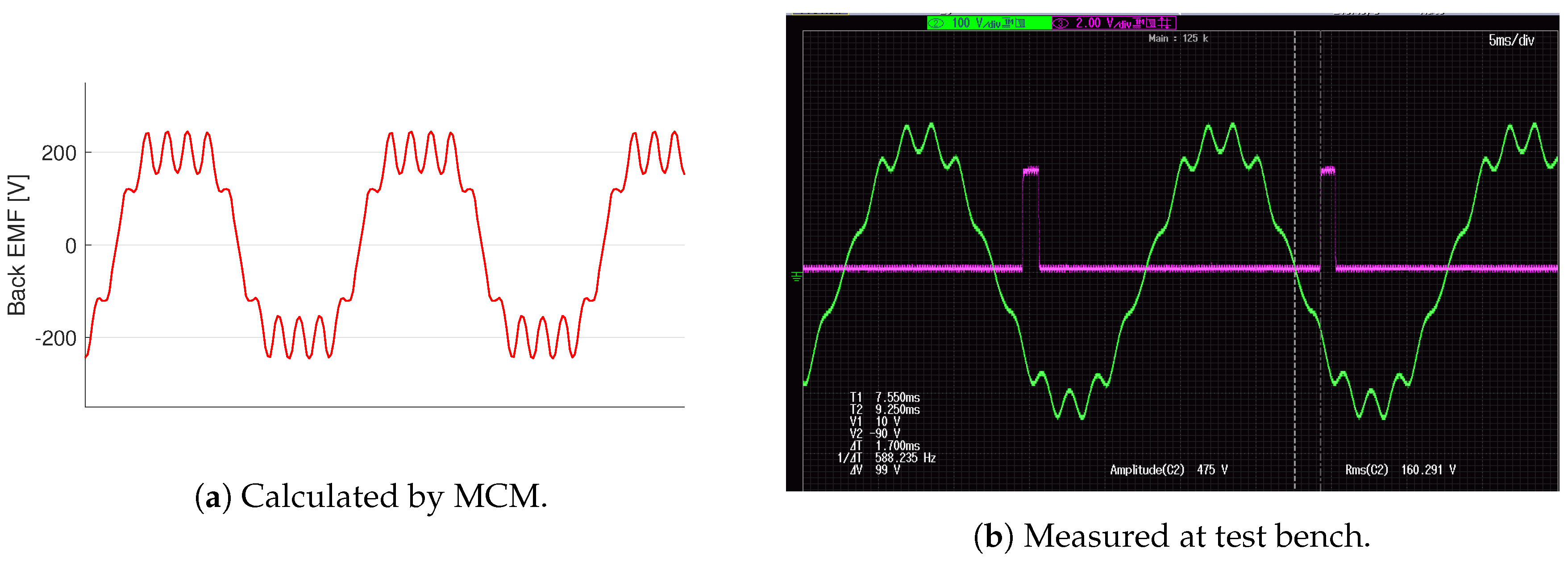
Finally, to visually compare the carried out measurements, in Figure 16, the obtained Back electromotive force waveform at tests and MCM is shown.
6. Conclusions
Nowadays, the use of PMSMs is exponentially increasing, with a specific interest in its use at very demanding conditions. Consequently, taking into account the different electromagnetic phenomena that take place inside the machine is crucial to predict in a very precise manner machine performance.
To this aim, in this paper, a general node mapping criterion for modelling highly saturated IPMSM using a magnetic reluctance network has been proposed. A MCM model, based on a magnetic reluctance network, is developed to model V-shaped interior mounted magnet rotors. The proposed MCM model allows selecting the discretization levels for the different machine parts. Furthermore, it not only allows simulating rotor motion but also considers the magnetic cross-coupling effect, the slotting effect and the iron magnetic saturation.
To validate the MCM model, Several V-shaped machines of different sizes and geometries were used together with FEM simulations. The results from these validations were remarkably accurate and efficient, requiring less time to complete the process. Finally, aiming to validate the MCM model with the suggested node mapping criterion, a real IPMSM prototype was tested. The comparison of the obtained results shows a great correspondence, proving the validity of the proposed method to determine highly saturated Interior PMSMs performance.
Overall, the present study expands the field of magnetic circuit models for highly saturated machines. Specifically, it provides the means to evolve within this area towards using the node mapping criterion to apply it to other highly demanded PMSM rotor solutions such as the Spoke type or the multilayer IPMSM. In addition, it would be interesting to analyse the way to optimize the implemented software code, as well as to study the use of other numerical analysis methods for solving nonlinear systems since it could lead to the development of an even faster machine designing tool.
Author Contributions
The presented work was carried out through the cooperation of all authors. D.C., B.P. and G.A. conducted the research and wrote the paper. I.E. and M.M.I. edited the manuscript and supervised the study.
Acknowledgments
This work was financially supported by the Basque Country Government Economic Development and Infraestructure Department, by means of grants program “ELKARTEK” (project KK20170095 Electromagnetic, mechanical and thermal study of light motors-MOTLIG).
Conflicts of Interest
The authors declare no conflict of interest.
Abbreviations
The following abbreviations are used in this manuscript:
| IPMSM | Interior mounted Permanent Magnet Synchronous Machine |
| MCM | Magnetic Circuit Model |
| FEM | Finite Elements Methods |
| EMF | Electromotive Force |
References
- Burress, T.; Campbell, S. Benchmarking EV and HEV power electronics and electric machines. In Proceedings of the 2013 Transportation Electrification Conference and Expo (ITEC), Detroit, MI, USA, 16–19 June 2013. [Google Scholar]
- Sun, L.; Cheng, M.; Jia, H. Analysis of a Novel Magnetic-Geared Dual-Rotor Motor With Complementary Structure. IEEE Trans. Ind. Electron. 2015, 62, 6737–6747. [Google Scholar] [CrossRef]
- Zheng, P.; Wang, W.; Wang, M.; Liu, Y.; Fu, Z. Investigation of the Magnetic Circuit and Performance of Less-Rare-Earth Interior Permanent-Magnet Synchronous Machines Used for Electric Vehicles. Energies 2017, 10, 2173. [Google Scholar] [CrossRef]
- Gu, W.; Zhu, X.; Quan, L.; Du, Y. Design and optimization of permanent magnet brushless machines for electric vehicle applications. Energies 2015, 8, 13996–14008. [Google Scholar] [CrossRef]
- Wu, W.; Zhu, X.; Quan, L.; Du, Y.; Xiang, Z.; Zhu, X. Design and Analysis of a Hybrid Permanent Magnet Assisted Synchronous Reluctance Motor Considering Magnetic Saliency and PM Usage. IEEE Trans. Appl. Supercond. 2018, 28, 1–6. [Google Scholar] [CrossRef]
- Yue, L.; Yulong, P.; Yanjun, Y.; Yanwen, S.; Feng, C. Increasing the saliency ratio of fractional slot concentrated winding interior permanent magnet synchronous motors. Electr. Power Appl. IET 2015, 9, 439–448. [Google Scholar] [CrossRef]
- Bai, J.; Zheng, P.; Tong, C.; Song, Z.; Zhao, Q. Characteristic Analysis and Verification of the Magnetic-Field- Modulated Brushless Double-Rotor Machine. IEEE Trans. Ind. Electron. 2015, 62, 4023–4033. [Google Scholar] [CrossRef]
- Sizov, G.; Ionel, D.; Demerdash, N. Modeling and Parametric Design of Permanent-Magnet AC Machines Using Computationally Efficient Finite-Element Analysis. IEEE Trans. Ind. Electron. 2012, 59, 2403–2413. [Google Scholar] [CrossRef]
- Parasiliti, F.; Villani, M.; Lucidi, S.; Rinaldi, F. Finite-Element-Based Multiobjective Design Optimization Procedure of Interior Permanent Magnet Synchronous Motors for Wide Constant-Power Region Operation. IEEE Trans. Ind. Electron. 2012, 59, 2503–2514. [Google Scholar] [CrossRef]
- Ruuskanen, V.; Nerg, J.; Pyrhonen, J.; Ruotsalainen, S.; Kennel, R. Drive Cycle Analysis of a Permanent-Magnet Traction Motor Based on Magnetostatic Finite-Element Analysis. Veh. Technol. IEEE Trans. 2015, 64, 1249–1254. [Google Scholar] [CrossRef]
- Zheng, P.; Zhao, J.; Liu, R.; Tong, C.; Wu, Q. Magnetic characteristics investigation of an axial-axial flux compound-structure PMSM used for HEVs. Magn. IEEE Trans. 2010, 46, 2191–2194. [Google Scholar] [CrossRef]
- Chong, L.; Rahman, M. Saliency ratio derivation and optimisation for an interior permanent magnet machine with concentrated windings using finite-element analysis. IET Electr. Power Appl. 2010, 4, 249–258. [Google Scholar] [CrossRef]
- Cavagnino, A.; Bramerdorfer, G.; Tapia, J.A. Optimization of Electric Machine Designs—Part I. IEEE Trans. Ind. Electron. 2017, 64, 9716–9720. [Google Scholar] [CrossRef]
- Hwang, C.C.; Cho, Y. Effects of leakage flux on magnetic fields of interior permanent magnet synchronous motors. IEEE Trans. Magn. 2001, 37, 3021–3024. [Google Scholar] [CrossRef]
- Zhu, L.; Jiang, S.; Zhu, Z.; Chan, C. Analytical Modeling of Open-Circuit Air-Gap Field Distributions in Multisegment and Multilayer Interior Permanent-Magnet Machines. IEEE Trans. Magn. 2009, 45, 3121–3130. [Google Scholar] [CrossRef] [Green Version]
- Chen, Q.; Liu, G.; Zhao, W.; Shao, M. Nonlinear adaptive lumped parameter magnetic circuit analysis for spoke-type fault-tolerant permanent-magnet motors. Magn. IEEE Trans. 2013, 49, 5150–5157. [Google Scholar] [CrossRef]
- Perho, J. Reluctance Network for Analysing Induction Machines; Helsinki University of Technology: Otaniemi, Finland, 2002. [Google Scholar]
- Vincent, R.; Emmanuel, V.; Lauric, G.; Laurent, G. Optimal sizing of an electrical machine using a magnetic circuit model: application to a hybrid electrical vehicle. IET Electr. Syst. Transp. 2015, 6, 27–33. [Google Scholar] [CrossRef]
- Raminosoa, T.; Rasoanarivo, I.; Meibody-Tabar, F.; Sargos, F.M. Time-Stepping Simulation of Synchronous Reluctance Motors Using a Nonlinear Reluctance Network Method. IEEE Trans. Magn. 2008, 44, 4618–4625. [Google Scholar] [CrossRef]
- Tangudu, J.K.; Jahns, T.M.; El-Refaie, A.; Zhu, Z. Lumped parameter magnetic circuit model for fractional-slot concentrated-winding interior permanent magnet machines. In Proceedings of the Energy Conversion Congress and Exposition, San Jose, CA, USA, 20–24 September 2009; pp. 2423–2430. [Google Scholar]
- Farooq, J.; Srairi, S.; Djerdir, A.; Miraoui, A. Use of permeance network method in the demagnetization phenomenon modeling in a permanent magnet motor. Magn. IEEE Trans. 2006, 42, 1295–1298. [Google Scholar] [CrossRef]
- Kuttler, S.; Benkara, K.; Friedrich, G.; Vangraefschepe, F.; Abdelli, A. Analytical model taking into account the cross saturation for the optimal sizing of IPMSM. In Proceedings of the 2012 XXth International Conference on Electrical Machines (ICEM), Marseille, France, 2–5 September 2012; pp. 2779–2785. [Google Scholar]
- Aden, A.; Amara, Y.; Barakat, G.; Hlioui, S.; De La Barriere, O.; Gabsi, M. Modeling of a radial flux PM rotating machine using a new hybrid analytical model. In Proceedings of the 2014 International Conference on Electrical Sciences and Technologies in Maghreb (CISTEM), Tunis, Tunisia, 3–6 November 2014; pp. 1–5. [Google Scholar]
- Amrhein, M.; Krein, P. Induction Machine Modeling Approach Based on 3-D Magnetic Equivalent Circuit Framework. IEEE Trans. Energy Convers. 2010, 25, 339–347. [Google Scholar] [CrossRef]
- Rasmussen, C.; Ritchie, E. A magnetic equivalent circuit approach for predicting PM motor performance. In Proceedings of the Conference Record of the 1997 IEEE Industry Applications Conference Thirty-Second IAS Annual Meeting, New Orleans, LA, USA, 5–9 October 1997; pp. 10–17. [Google Scholar]
- Lovelace, E.; Jahns, T.; Lang, J.H. A saturating lumped-parameter model for an interior PM synchronous machine. IEEE Trans. Ind. Appl. 2002, 38, 645–650. [Google Scholar] [CrossRef] [Green Version]
- Yamazaki, K.; Kumagai, M. Torque Analysis of Interior Permanent-Magnet Synchronous Motors by Considering Cross-Magnetization: Variation in Torque Components With Permanent-Magnet Configurations. IEEE Trans. Ind. Electron. 2014, 61, 3192–3201. [Google Scholar] [CrossRef]
- Lee, S.; Jeong, Y.S.; Kim, Y.J.; Jung, S.Y. Novel Analysis and Design Methodology of Interior Permanent-Magnet Synchronous Motor Using Newly Adopted Synthetic Flux Linkage. IEEE Trans. Ind. Electron. 2011, 58, 3806–3814. [Google Scholar]
- Ostovic, V. Dynamics of Saturated Electric Machines; Springer: New York, NY, USA, 1989. [Google Scholar]
- Han, S.H.; Jahns, T.; Soong, W. A Magnetic Circuit Model for an IPM Synchronous Machine Incorporating Moving Airgap and Cross-Coupled Saturation Effects. In Proceedings of the Electric Machines & Drives 2007 International Conference, Antalya, Turkey, 3–5 May 2007; pp. 21–26. [Google Scholar]
- Ong, C.M. Dynamic Simulation of Electric Machinery: Using MATLAB/SIMULINK; Upper Saddle River: Bergen, NJ, USA, 1998. [Google Scholar]
Figure 1.
Nodal element structure.
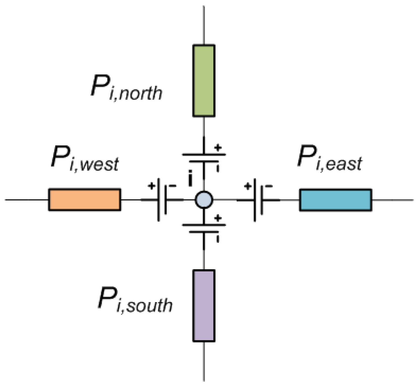
Figure 2.
Stator nodal model.
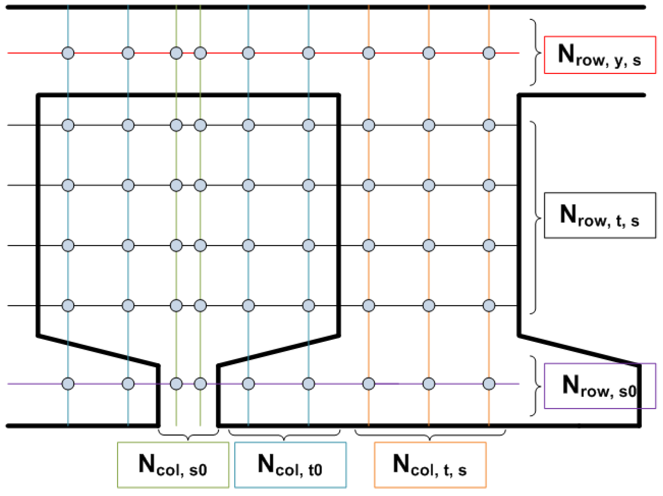
Figure 3.
Half pole rotor nodal model for V-shaped PMSMs.

Figure 4.
Whole pole rotor nodal model for V-shaped PMSMs.

Figure 5.
Rotor nodal model for V-shaped PMSMs.

Figure 6.
Rotor nodal model for embedded PMSMs.

Figure 7.
Airgap nodal model.

Figure 8.
Airgap multinode linking.

Figure 9.
Magnetic flux density distribution for the three motors.

Figure 10.
MCM node mapping relative error.
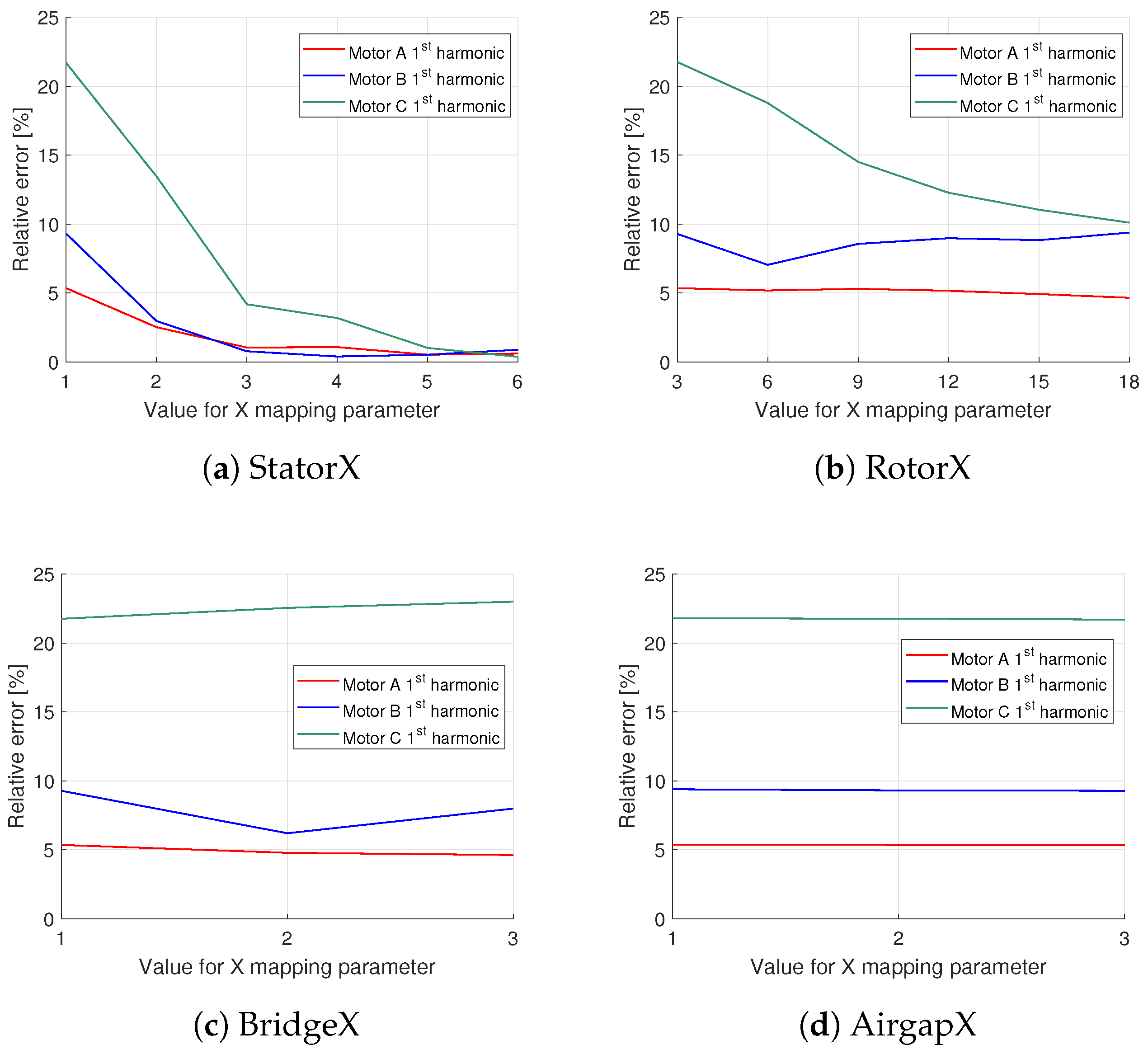
Figure 11.
Phase magnetic flux linkage (Motor A).
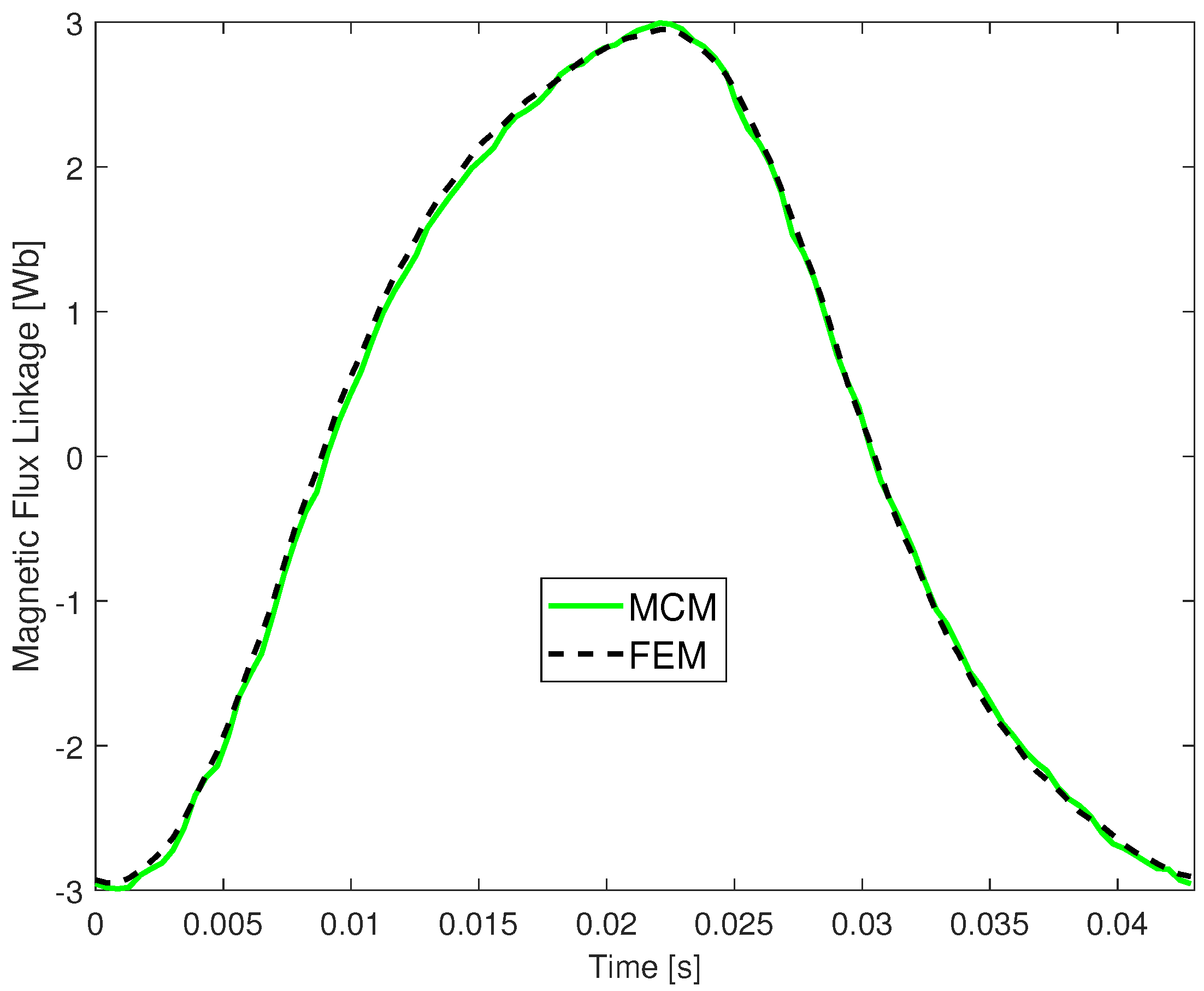
Figure 12.
Airgap magnetic flux density at no load condition (Motor A).

Figure 13.
Normalized time simulation vs MCM node map.
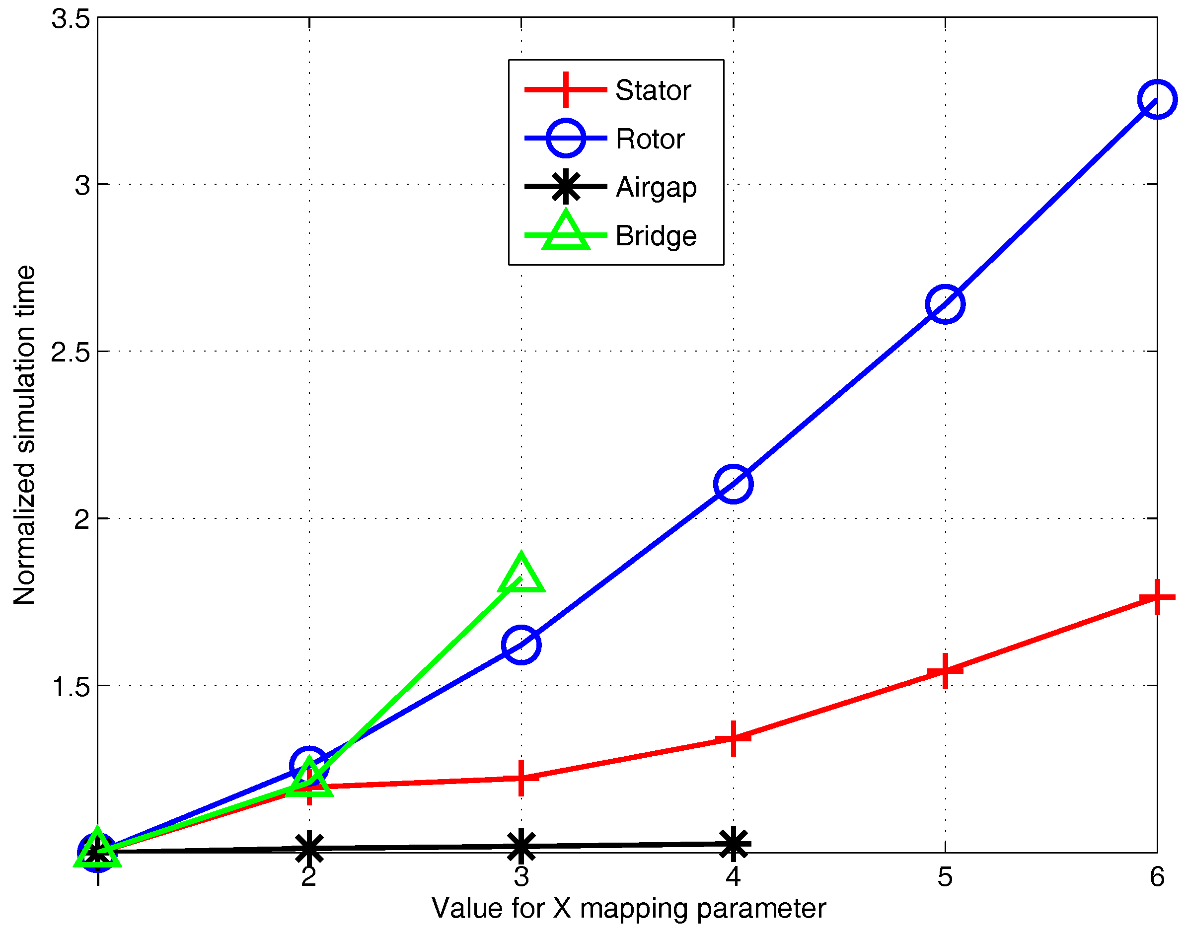
Figure 14.
Prototype’s Magnetic flux density distribution.
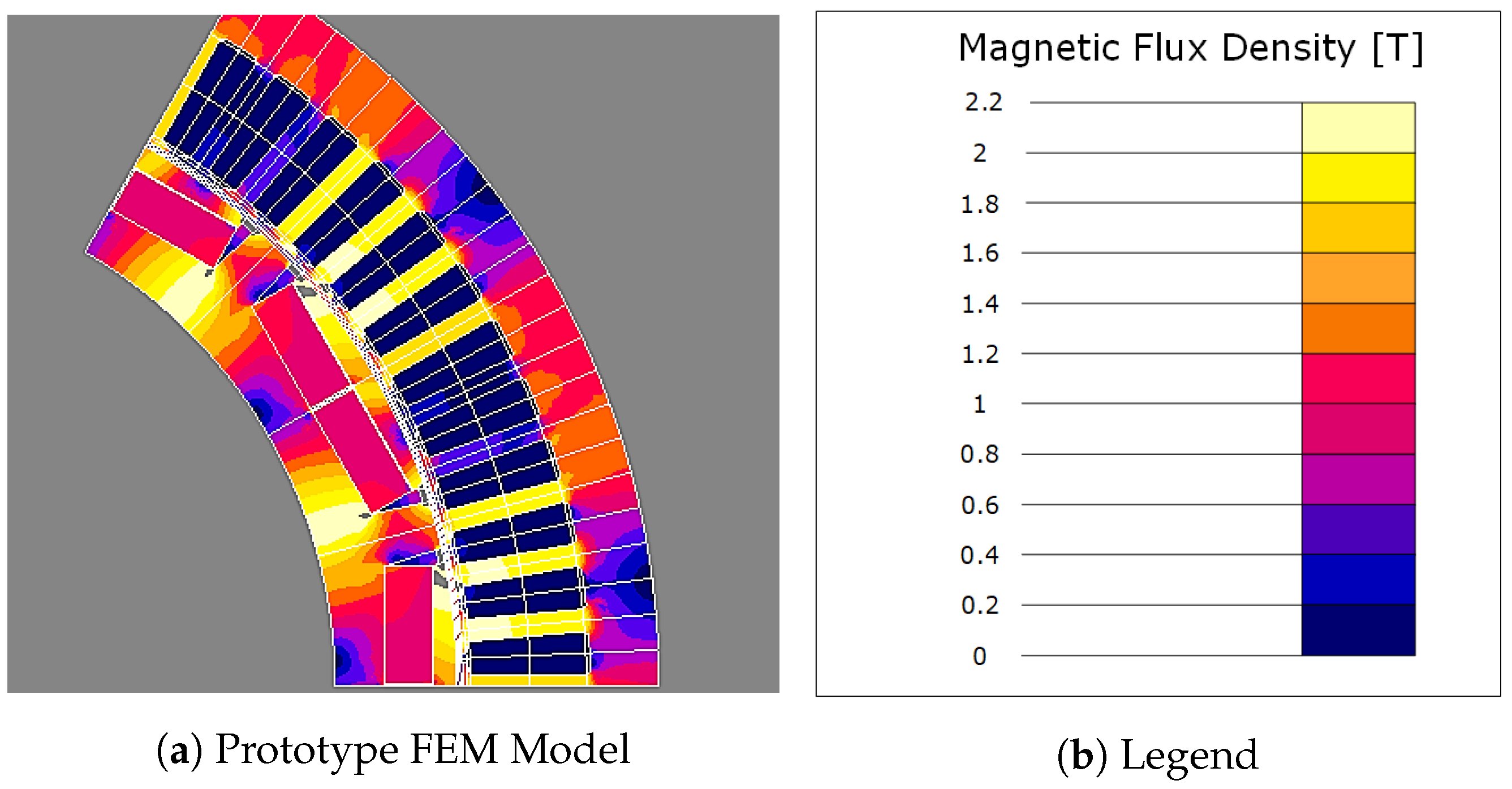
Figure 15.
IPMSM Prototype at test bench.
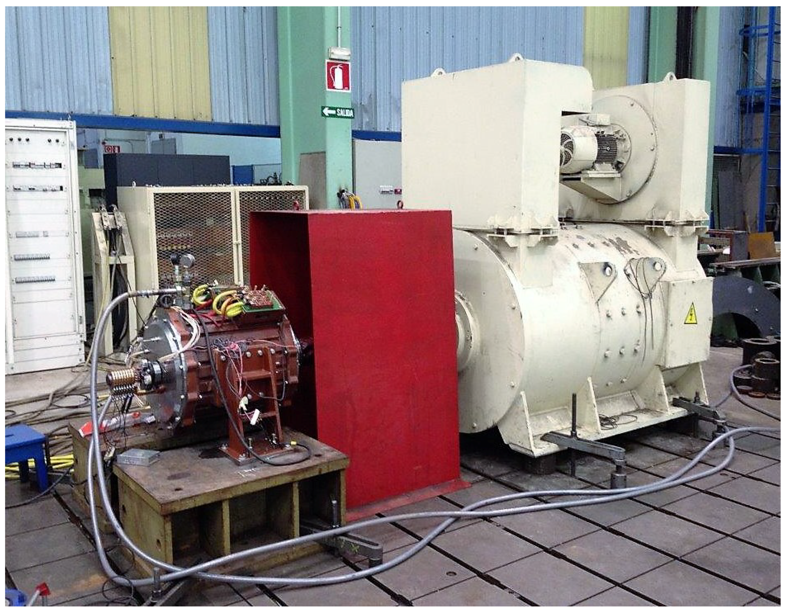
Figure 16.
Protype’s Back EMF at 50% rated speed.


Table 1.
Stator reluctance network parameters.
| Definition | Parameter | Value (See Figure 2) |
|---|---|---|
| Yoke rows | 1 | |
| Tooth rows | 4 | |
| Tooth-tip rows | 1 | |
| Tooth columns | 3 | |
| Tooth-tip columns (One side) | 2 | |
| Slot-opening columns | 2 |
Table 2.
IPMSM rotor reluctance network parameters.
| Definition | Parameter | Value (See Figure 3) |
|---|---|---|
| PM rows | 1 | |
| Bridge rows | 1 | |
| Bridge columns | 1 | |
| Bridge inter pole columns | 1 | |
| PM columns | 3 |
Table 3.
V-shaped IPMSM characteristics.
| Parameter | Motor A | Motor B | Motor C |
|---|---|---|---|
| Number of poles | 4 | 6 | 8 |
| Number of slots | 48 | 54 | 24 |
| Airgap length [mm] | 2 | 2 | 1 |
| Stator outer diameter [mm] | 820 | 370 | 150 |
| Rotor outer diameter [mm] | 570 | 276 | 108 |
| Stack length [mm] | 820 | 404 | 300 |
| V-shaped PM depth [mm] | 100 | 24 | 10 |
| V-shaped PM height [mm] | 9 | 5 | 3.5 |
| Stator yoke height [mm] | 64 | 28 | 10 |
| Stator slot width [mm] | 15 | 6.5 | 6 |
| Magnet remanence [T] | 1.304 | 1.304 | 1.13 |
| Magnet relative permeability | 1.06 | 1.06 | 1.04 |
Table 4.
Load operation point.
| Parameter | Motor A | Motor B | Motor C |
|---|---|---|---|
| Output power [kW] | 147 | 180 | 50 |
| Speed [r/min] | 700 | 1250 | 2500 |
| Phase current RMS [A] | 160 | 400 | 130 |
| q-component current [A] | 148 | 392 | 125 |
| d-component current [A] | −60 | −79 | −34 |
Table 5.
FEM measured .
| Region | Motor A | Motor B | Motor C |
|---|---|---|---|
| Stator Tooth [T] | 1.8 | 2.0 | 1.5 |
| Stator Core [T] | 1.9 | 1.9 | 1.6 |
| Rotor Bridge [T] | 2.3 | 2.5 | 2.6 |
| Rotor Core [T] | 1.6 | 1.5 | 1.4 |
Table 6.
MCM node mapping employed in the analysis.
| Parameter | StatorX | AirgapX | BridgeX | RotorX |
|---|---|---|---|---|
| X | 1 | 1 | 1 | |
| X | 1 | 1 | 1 | |
| X | 1 | 1 | 1 | |
| X | 1 | 1 | 1 | |
| X | 1 | 1 | 1 | |
| 1 | 1 | X | 1 | |
| 2 | 2 | 2 | 2 | |
| 3 | 3 | 3 | ||
| 1 | 1 | X | 1 | |
| 1 | 1 | X | 1 | |
| 2 | X | 2 | 2 |
Table 7.
FEM results.
| 1st Harmonic | 3rd Harmonic | |
|---|---|---|
| Motor A | 2988 mWb | 250 mWb |
| Motor B | 702 mWb | 29.4 mWb |
| Motor C | 246 mWb | 14 mWb |
Table 8.
MCM node mapping relative error values.
| 1st Harmonic [%] | 3rd Harmonic [%] | |||||
|---|---|---|---|---|---|---|
| Motor | A | B | C | A | B | C |
| Stator1 | 5.3 | 9.3 | 21.7 | 9.1 | 12.2 | 15.1 |
| Stator2 | 2.5 | 3.0 | 13.5 | 7.7 | 12.9 | 11.8 |
| Stator3 | 1.0 | 0.8 | 4.2 | 2.6 | 15.3 | 7.4 |
| Stator4 | 1.1 | 0.4 | 3.2 | 0.8 | 13.7 | 8.4 |
| Stator5 | 0.5 | 0.5 | 1.0 | 2.1 | 15.2 | 6.3 |
| Stator6 | 0.6 | 0.4 | 0.4 | 0.4 | 13.8 | 7.2 |
| Rotor3 | 5.4 | 9.3 | 21.8 | 9.1 | 12.6 | 15.0 |
| Rotor6 | 5.2 | 7.0 | 18.8 | 7.2 | 25.5 | 14.2 |
| Rotor9 | 5.3 | 8.6 | 14.5 | 1.3 | 15.8 | 9.5 |
| Rotor12 | 5.2 | 9.0 | 12.3 | 10.0 | 22.9 | 8.1 |
| Rotor15 | 4.9 | 8.8 | 11.0 | 12.3 | 27.2 | 12.6 |
| Rotor18 | 4.6 | 9.4 | 10.1 | 13.9 | 28.1 | 6.1 |
| Bridge1 | 5.4 | 9.3 | 21.8 | 9.2 | 12.6 | 15.0 |
| Bridge2 | 4.8 | 6.2 | 22.5 | 16.7 | 13.5 | 15.0 |
| Bridge3 | 4.6 | 8.0 | 23.0 | 12.3 | 7.2 | 15.1 |
| Airgap1 | 5.4 | 9.4 | 21.8 | 9.1 | 12.0 | 14.7 |
| Airgap2 | 5.3 | 9.3 | 21.8 | 9.2 | 12.2 | 15.0 |
| Airgap3 | 5.3 | 9.3 | 21.7 | 9.3 | 12.2 | 15.0 |
Table 9.
Load performance.
| Value | Relative Error [%] | ||||||
|---|---|---|---|---|---|---|---|
| Motor | A | B | C | A | B | C | |
| Torque [N· m] | 2005 | 1370 | 173 | 0.2 | −0.5 | −4.8 | |
| [V] | 1st harm | 434.0 | 285.8 | 285.2 | −0.7 | 3.6 | 6.3 |
| 3rd harm | 103.1 | 38.9 | 42.8 | −7.1 | 5.0 | −2.7 | |
Table 10.
Computational time MCM vs FEM.
| Number of Elements | Computation Time [s] | |||
|---|---|---|---|---|
| MCM | FEM | MCM | FEM | |
| Motor A | 424 | 53154 | 1.3 | 9.1 |
| Motor A | 364 | 21149 | 1.2 | 3.6 |
| Motor A | 208 | 25067 | 1.4 | 5.1 |
Table 11.
Airgap region nodal information.
| Node Map | Nodes per Pole Pair | Average Nodes Distance [mm] | Nodes per Slot Pitch | ||||||
|---|---|---|---|---|---|---|---|---|---|
| A | B | C | A | B | C | A | B | C | |
| Stator1 | 72 | 60 | 36 | 12.4 | 4.8 | 2.4 | 3 | 3.3 | 6 |
| Stator2 | 120 | 96 | 48 | 7.5 | 3.0 | 1.8 | 5 | 5.3 | 8 |
| Stator3 | 168 | 132 | 60 | 5.3 | 2.2 | 1.4 | 7 | 7.3 | 10 |
| Stator4 | 216 | 168 | 72 | 4.2 | 1.7 | 1.2 | 9 | 9.3 | 12 |
| Stator5 | 264 | 204 | 84 | 3.4 | 1.4 | 1.0 | 11 | 11.3 | 14 |
| Stator6 | 312 | 240 | 96 | 2.9 | 1.2 | 0.9 | 13 | 13.3 | 16 |
| Rotor3 | 72 | 60 | 36 | 12.4 | 4.8 | 2.4 | 3 | 3.3 | 6 |
| Rotor6 | 84 | 72 | 48 | 10.6 | 4.0 | 1.8 | 3.5 | 4 | 8 |
| Rotor9 | 96 | 84 | 60 | 9.3 | 3.5 | 1.4 | 4 | 4.6 | 10 |
| Rotor12 | 108 | 96 | 72 | 8.3 | 3.0 | 1.2 | 4.5 | 5.3 | 12 |
| Rotor15 | 120 | 108 | 84 | 7.5 | 2.7 | 1.0 | 5 | 6 | 14 |
| Rotor18 | 132 | 120 | 96 | 6.8 | 2.4 | 0.9 | 5.5 | 6.6 | 16 |
Table 12.
Tested IPMSM characteristics.
| Parameter | Value |
|---|---|
| Output power [kW] | 225 |
| Voltage [V] | 318 |
| Stator outer diameter [mm] | 420 |
| Rotor outer diameter [mm] | 317 |
| Stack length [mm] | 380 |
| Magnet quality | N40UH |
Table 13.
Prototype’s performance calculated via proposed MCM and FEM.
| Parameter | MCM | FEM | Relative Error [%] |
|---|---|---|---|
| Back EMF [V] | 329 | 315 | 4.4 |
| Electromagnetic Power [kW] | 230 | 224 | 2.7 |
| Phase current [A] | 434 | 434 | 0.0 |
| Power factor | 0.99 | 0.99 | 0.9 |
| Line Voltage [V] | 316 | 305 | 3.3 |
| D-axis load Magnetic flux linkage [mWb] | 316 | 300 | 5.4 |
| Q-axis load Magnetic flux linkage [mWb] | 271 | 273 | 0.8 |
| Stator Tooth load Magnetic flux density [T] | 2.2 | 2.1 | 6.3 |
| Stator Core load Magnetic flux density [T] | 1.4 | 1.4 | 2.9 |
| Rotor Bridge load Magnetic flux density [T] | 2.5 | 2.8 | 10.7 |
| Rotor Core load Magnetic flux density [T] | 2.0 | 2.1 | 3.4 |
Table 14.
Prototype measured performance at test bench.
| Parameter | MCM | Test | Relative Error [%] |
|---|---|---|---|
| Back EMF [V] | 329 | 302 | 8.9 |
| Mechanical Power [kW] | 225 | 223 | 0.9 |
| Phase current [A] | 434 | 425 | 2.1 |
| Power factor | 0.99 | 0.99 | 0.8 |
| Line Voltage [V] | 318 | 318 | 0.0 |
© 2018 by the authors. Licensee MDPI, Basel, Switzerland. This article is an open access article distributed under the terms and conditions of the Creative Commons Attribution (CC BY) license (http://creativecommons.org/licenses/by/4.0/).
Share and Cite
MDPI and ACS Style
Caballero, D.; Prieto, B.; Artetxe, G.; Elosegui, I.; Martinez-Iturralde, M. Node Mapping Criterion for Highly Saturated Interior PMSMs Using Magnetic Reluctance Network. Energies 2018, 11, 2294. https://doi.org/10.3390/en11092294
AMA Style
Caballero D, Prieto B, Artetxe G, Elosegui I, Martinez-Iturralde M. Node Mapping Criterion for Highly Saturated Interior PMSMs Using Magnetic Reluctance Network. Energies. 2018; 11(9):2294. https://doi.org/10.3390/en11092294
Chicago/Turabian StyleCaballero, Damian, Borja Prieto, Gurutz Artetxe, Ibon Elosegui, and Miguel Martinez-Iturralde. 2018. "Node Mapping Criterion for Highly Saturated Interior PMSMs Using Magnetic Reluctance Network" Energies 11, no. 9: 2294. https://doi.org/10.3390/en11092294
Note that from the first issue of 2016, this journal uses article numbers instead of page numbers. See further details here.