A Hybrid Building Power Distribution System in Consideration of Supply and Demand-Side: A Short Overview and a Case Study

College of Architecture and Urban Planning, Tongji University, Shanghai 200092, China
*
Author to whom correspondence should be addressed.
Energies 2018, 11(11), 3082; https://doi.org/10.3390/en11113082
Submission received: 8 October 2018
/
Revised: 3 November 2018
/
Accepted: 6 November 2018
/
Published: 8 November 2018
(This article belongs to the Special Issue Selected Papers from the 9th Edition of the International SOLARIS Conference)
Abstract
:As the quantity of direct current (DC) load and wireless power transmission (WPT) devices are continuously increasing in building, in order to efficiently utilize renewable energy (which outputs DC power) such as photovoltaic (PV), especially for building integrated photovoltaic (BIPV), and regeneration energy from elevators (which also outputs DC power), a novel building power distribution system architecture is explored in consideration of the characteristics of supply and demand-side in this paper. The proposed architecture is a hybrid framework integrated with conventional alternating current (AC) power distribution system, DC power distribution and WPT system. The applied AC and DC hybrid power distribution system has higher conversion efficiency than a single AC power system, which indicates that the former is becoming an important trend of building power distribution. In addition, the results of experimental test in a case study suggest that the proposed architecture can provide fine service for efficient application of renewable energy and regeneration energy in building. The obtained results also can serve as a foundation to promote the development of building power distribution system and related practical application in building.
1. Introduction
Since the 1880s, Tesla and Edison have had a drastic debate on the technology of direct current (DC) or alternating current (AC) power distribution. In addition, the AC power distribution system predominates eventually.
Nowadays, huge changes have taken place. From the point of the demand-side, there are plenty of loads in building that require DC power supply, such as computer and network equipment, Light Emitting Diode (LED) lighting, elevators, inverter air-conditioners, and electric vehicle batteries which will be widely used in future. In addition, the wireless power transmission (WPT) technology has been applied to the field of household appliances and electric vehicles. From the point of supply-side, there is a significant increase in the field of distributed energy [1,2,3,4,5,6,7] resources. These sources include renewable energy of elevators, photovoltaic power, micro turbines, wind power, and fuel cells, all of which can provide DC power to the building. Especially for elevators and building integrated photovoltaic (BIPV) [8,9,10,11,12,13], they generate DC power directly. However, the existing building power distribution system is based on AC system, so that DC energy should be converted from DC to AC, then AC to DC. If DC power is fed to the DC bus directly, the power conversion efficiency can be greatly improved. Therefore, it is urgent to develop a DC distribution system to adapt to the needs of DC renewable energy and DC load.
For the application of DC renewable energy distributed generation, scholars have proposed concept of micro-grid [14,15,16]. DC micro-grid is a branch of the general micro-grid. DC micro-grid [17,18,19] is a combination of a grid in the form of DC power, DC loads and control devices. It includes elevator renewable power generation, micro turbines, wind power, solar power, fuel cells and some other distributed power and energy storage devices [20,21,22,23]. With a common DC system, all the individually controllable micro-power devices are connected together.
There has been a large amount of research on micro-grids from many scholars of various countries, but much less of the study on DC micro-grid or building distribution systems. The research on micro-grid in the U.S. is mainly carried out through three projects [24]: (1) Micro-grid research program fund financed by the U.S. Department of Energy’s Office of Energy Reliability Transmission and California Energy Commission (CEC); (2) cooperation by the U.S. Department of Energy and the GE Company, the control, protection and energy management in one integrated micro-grid; (3) Distributed Utility Integrated Test (DUIT) project financed by CEC. Micro-grid research of EU [25] is divided into two stages: The first stage is the Fifth Framework Programme (FP5), which has made some enlightening research results; the second stage is the Sixth Framework Programme (FP6), whose research spread into controllers, better control strategies, control and integration, standards, impact of micro-grid communications, and some tests. Currently, the European micro-grid demonstration projects are the Greek Island Snow micro-grid, Germany Mannheim residential demonstration project, Spain LABEIN project, Portugal Distribuição e parceiros Europeus (EDP) project, Italy Clean Energy Solutions, Inc. (CESI) project and Denmark ELTRA project [25]. Researches on micro-grids in Japan [26] stress the diversification of energy supply, reducing pollution, meeting the user’s individual power needs, emphasizing micro-grid control and electrical energy storage. So far, Japan is the world’s leader in building micro-grid demonstration projects.
DC micro-grid research in China is just starting out. On September 14 of 2012, the National Energy Board issued a declaration of distributed PV on large-scale demonstration zone notice of distributed photovoltaic power generation projects (including the construction of BIPV) to implement a fixed unit of electricity subsidies, spontaneous own use and excess electricity grid electricity subsidies unified standard.
In addition, WPT technology can be traced back to a century ago when Nicola Tesla introduced near-field coupling of two loop resonators based on magnetic resonance. Due to the strong attenuation of energy transfer efficiency with the increase of distance, the wireless power transfer technology is only suitable for the application in short distances (millimeter sized). In household electrical appliances (such as notebook computers, mobile phones), it requires electric energy in the distance (meter sized) to achieve efficient and reliable non-contact transmission [27]. In 2007, Massachusetts Institute of Technology (MIT) Assistant Professor Marin Soljacic and his research team contributed their achievements to “Science” in the field of wireless power transmission [28]. With adjusting the resonant frequency of the transmitter and receiver coils, they achieved the electromagnetic resonance and utilized a self-made device to lighten 60 W electric lamp over distances in excess of meters away. The transmission efficiency is approximately 40%, and it makes a breakthrough of wireless power transmission. The implementation of this technology has aroused great interest in academia and the industry.
In recent years, with the development of electronic equipment (intelligent mobile phones, tablet computers), the actual demand for wireless charging and the development of smart home furnishing and electric vehicle charging, people increasingly hope to remove the final cable of electrical equipment. Therefore, the trend of the wireless demand [29,30,31] of electrical equipment will be significant in the future. In traditional AC systems, WPT technology requires that low frequency AC is transformed to DC power, and then DC power is converted to high frequency AC. If WPT technology is applied in DC system directly, rectifier [32,33,34] (AC/DC) can be cut down and the power conversion efficiency can be greatly improved. Therefore, the DC system is suitable for WPT technology.
Taking the characteristics of supply and demand-side as well as the demand of WPT into account, the architecture of AC-DC hybrid building power distribution system with a wired/wireless system is proposed in this paper. This hybrid building power distribution system can promote efficiency, which is the tendency of building power distribution system.
The remainder of the paper is organized as follows: Section 2 and Section 3 present the characteristics of distributed energy and elevator regeneration energy in supply-side and DC load in the demand-side, respectively. Based on supply-side and demand-side, the DC power distribution system is presented in Section 4. In Section 5, the fundamental principle and applicative architecture of WPT in the AC system are presented. On the basis mentioned above, the architecture of the AC-DC hybrid building power distribution system is proposed in Section 6. The designed micro-grid is verified by experiments in a high-rise building in Section 7. Finally, concluding remarks are offered in Section 8.
2. The Characteristics of Energy Supply-Side in Building
This section presents the characteristics of distributed energy and elevator regeneration energy, for which DC system is suitable.
2.1. Renewable Energy and Distributed Generation
At present, the renewable energy is mainly solar energy, wind energy, hydropower, biomass, geothermal energy, ocean energy, etc., and the distributed generation is mainly photovoltaic power generation, wind power generation, hydropower generation, gas power generation, fuel cell, etc.
Photovoltaic (PV) power generation and fuel cell directly generate electricity in the form of DC. It is direct DC power supply. It needs a DC/AC inverter [35,36,37] to integrate into the traditional AC distribution network.
The wind power generation [38,39,40,41,42] and gas turbine [43,44,45] generate electricity in the form of AC. Due to the different rotation frequency of the impeller, the frequency of the AC power is not 50/60 Hz and not directly incorporated into the AC-grid. It is necessary that the distributed generation is incorporated into the AC-grid through AC/DC/AC. In a sense, it can be considered as an indirect DC power supply.
How to use the renewable energy and distributed generation efficiently is critical to energy conservation [46,47]. Therefore, if the DC distribution system is used, the use of a DC/AC converter in the distribution link can be greatly reduced, which not only reduces the cost of the grid construction and improves the reliability of the grid, but also reduces the loss in the transformation of power and the transmission process.
With the rapid and comprehensive application of the renewable energy and the distributed generation, the advantages of DC distribution are highlighted. It is urgent to develop a DC distribution system and DC microgrid to adapt the needs of energy development.
2.2. Elevator Regeneration Energy
In the electric drive system, motor inevitably has the braking state, namely the power generation process. In this process, because of the motor rotor with external load or the its moment of inertia, the actual speed of the motor is more than the synchronous speed of the output of inverter. Similarly, the elevator as a potential load frequently could be in the energy generating state while the elevator is running. In the elevator with AC-DC-AC frequency conversion, the regenerative energy is stored in a filter capacitor in the variable frequency DC bus, so that the voltage in the DC bus will gradually increase, and if DC power is not timely released from the capacitor, it will cause the lift to stop running due to overvoltage.
At present, there are three methods for dealing with regeneration electricity from an elevator [48]. First, the regeneration energy can be consumed in the brake unit or the brake resistor. Second, the regeneration electricity can be transformed to AC power into public grid. Third, the elevator regeneration energy can be stored for other electrical equipment.
(1) To be consumed in the brake unit or the brake resistor
At present, more than 98% of elevators consume DC energy stored in filter capacitor, by heating the regenerative resistor. The regenerative resistor is pre-linked up to the DC bus. When the voltage of the DC bus exceeds the preset value, the regenerative resistor is linked up to the DC bus, and regeneration energy, which is stored in filter capacitor, is consumed by heating the regenerative resistor, until the voltage of the DC bus is lower than the pre-set value. However, it will not only cause energy waste, but also increase the room temperature, so that the room needs to have a heat abstractor installed for cooling, which results in energy waste. Jun Guo and Jinwei Fan introduce an automatic diagnostic method of the coil wearing state through measuring the acceleration curve of the running coil, which is vital for the safety maintenance of the elevator [49].
(2) To be transformed to AC power into public grid
DC power, which is stored in the capacitor, can be transformed to AC power into public grid, so that there is an obvious energy saving effect. Due to no resistor, the room temperature will not increase, which can save the energy consumption of air conditioning or cooling equipment. Marsong and Plangklang design an energy-regenerative unit for an elevator system, which can feed electricity back into a power grid [50]. However, the renewable energy of the elevator, as distributed energy, has the characteristics of randomness and intermittence, which will cause a certain degree of impact on the quality of electricity. In addition, the renewable energy of the elevator works with the building distribution network, so that it will change the characteristic of unidirectional power flow in a traditional building distribution system. Therefore, the technology has matured, but it is difficult to popularize this technology. Mesemanolis et al. introduce the energy management system, which is implemented through an adaptive neuro-fuzzy controller that adjusts the acceleration/deceleration and rotational speed of the motor according to a fuzzy rale set governed by the travel distance of the elevator and the load [51].
(3) To be stored for other electrical equipment
When the elevator is in the state of power generation, the technology of energy feedback can transform mechanical energy of the elevator into electricity, and it can be stored in the energy storage device, then the stored power through the DC-to-AC inverter can be supplied to other electrical equipment. This technology can be in not only on-grid but also off-grid operation with relative flexibility. However, a set of energy storage devices needs to be installed for every elevator, and the cost of the energy storage device is relatively higher. Therefore, this technology has a poor economy, which restricts its popularization and application.
In summary, transforming renewable electricity to AC power into public grid has obvious effect of energy saving, but the regenerative energy has randomness and intermittence, which will cause a certain degree of impact on the quality of electricity. At present it cannot be widely applied. Storing renewable energy for other electrical equipment because of the energy storage device, has poor economy. Therefore, it is necessary to further search after the technology of utilization for elevator regeneration energy with better economics for solving the problem of elevator regeneration energy waste.
In this paper, we suggest the elevator regeneration energy feed to a DC system which is highly efficient and energy saving.
3. The Change of Terminal Load on the Demand-Side
This section presents the development of DC load and WPT demand, which is conductive to being plugged in DC system.
3.1. The Increase of the Proportion of DC Load on the Demand-Side
In recent years, with the development of electronic technology and network communication technology, the proportion of DC load on the demand-side has increased. The result of research showed that certain types of buildings and even the DC load proportion is more than 90% [52], and these changes are mainly in two aspects.
First, the quantity of the electrical appliances with DC increases. The most common and most representative electrical appliance is the frequency conversion device. In recent years, with the maturity of frequency conversion technology and the reduction of product cost, a large number of frequency conversion electrical appliances have been developed, produced, promoted and applied, such as elevators, air conditioners, refrigerators, washing machines and other frequency conversion devices.
Second, an increasing number of electrical equipment are essentially DC-driven appliances, which need to transform traditional AC power into DC, such as the common electric cars, electric bicycles, LCD TVs, LED lighting, computers, network equipment, mobile phones and so on.
The increase of DC load in the user terminal is the inner driving force for developing DC power distribution and DC micro-grid.
3.2. The Development of WPT on the Demand-Side
In recent years, wireless power transmission (WPT) has rapidly developed. WPT technology is mainly based on the electromagnetic induction, electromagnetic radiation, electromagnetic resonance and so on. There are three technical schemes based on wireless power transmission in intelligent buildings [53].
(1) Microwave radio energy transmission technology usually adopts S band and C band (wavelength is from hundreds of meters to thousands of meters), and is suitable for high-precision directional energy transmission and long-distance transmission, such as low orbit and synchronous orbit satellites, power supply for aerospace vehicles, etc.
(2) WPT technology based on the principle of electromagnetic induction is easily realized. The working frequency is from tens to hundreds of kHz, and the transmission distance from several millimeters to several meters. The transmission power is large, and transmission efficiency with short distance is high, up to 99%, but energy transfer efficiency has the strong attenuation with the increase of distance [54]. It has a wide range of applications, such as electric vehicles and medical micro robots.
(3) WPT based on the principle of the electromagnetic resonance is still in the experimental stage. The frequency is from several MHz to dozens of MHz, and the transmission distance is from several centimeters to several meters with less electromagnetic radiation and electromagnetic interference.
Therefore, the transmission distance of WPT based on electromagnetic resonance is longer than electromagnetic induction. If there is a breakthrough in the transmission efficiency in future, it would be possible to apply WPT based on electromagnetic resonance in many fields. It is predictable, WPT technology will be derived from the wireless home appliances, wireless power supply equipment, especially mobile phones, portable computers and mobile power.
4. DC Power Distribution System in Buildings
According to Section 2 and Section 3, the DC power distribution system is presented in this section.
4.1. Architecture
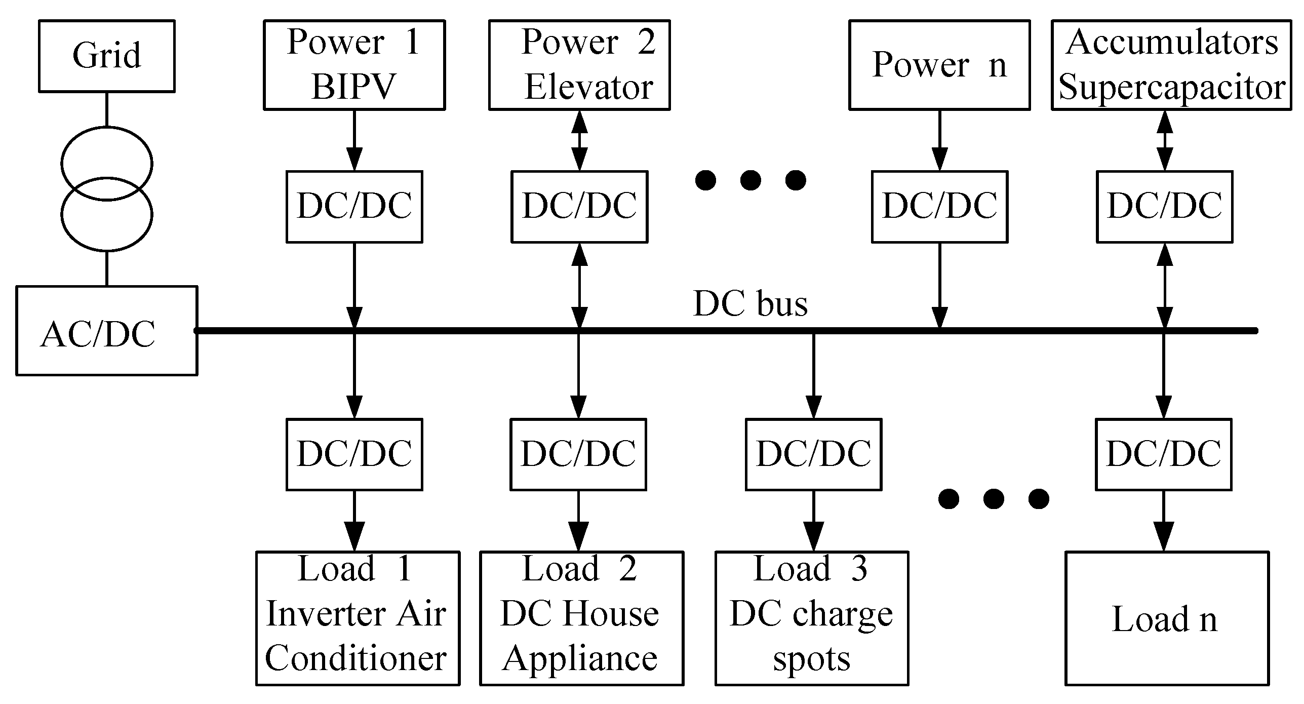
DC power distribution system structure is configured as shown in Figure 1 [55]. It can be divided as AC/DC converter, the DC bus, the distributed power supply, DC loading, storage, switching and protective devices (not shown in the following figure).
Article [56] gave an overview of the key technology of DC power distribution systems. Japanese researchers consider taking 380 V DC bus voltage is more appropriate and has been recognized by the relative American organizations, and also a dual bus system including using a DC/DC converter to get a 45 V low voltage [56,57], that means a large high voltage to the power DC load to provide power, while low-voltage to low-power appliances. However, DC power distribution system should particularly pay attention. Protective devices, such as circuit breakers, can improve the reliability of the system. Additionally, there has already been some mature practical application [58].
The AC/DC converter with six insulated gate bipolar transistors (IGBT) can be constructed into a bidirectional converter. Its role is the rectifier to provide controlled power to the DC bus when the distributed power supply in the building cannot meet the current load of electricity. The IGBT rectifier overcomes the problem of low power factor and harmonics which exists in conventional diode bridge rectifier circuits, and electromagnetic compatibility (EMC) harmonics to a minimize point. When distributed power generation has an excess load, the AC/DC converter can transport DC side of the inverter to the grid electricity. However, if the distributed power capacity is small, which means that the power grid may not allow feedback, this time the AC/DC converter can be used as a simple inexpensive bridge rectifier circuit, with only one-way transmission of AC power to the DC load. AC/DC converter output voltage should be lower than the normal DC bus voltage, and only work when the bus voltage is below the set threshold.
4.2. Voltage Levels
The voltage level is one of the important factors of the DC distribution system. The inappropriate voltage level could have a significant impact on the economy, safety and development of power grid construction and operation. According to DC voltage levels of rail transportation, communications, shipbuilding and so on (Table 1), with considering the relevant factors of DC distribution system, article [59] selected 240 V, 336 V, 380 V preliminarily as the voltage level of low voltage distribution; then the article used the fuzzy comprehensive evaluation method to evaluate the three voltage levels (Table 2); finally, the article came to the conclusion that the optimal scheme for low voltage distribution is 380 V. The problem of the disunity of voltage level and small capacity DC load can be solved by commutation technology.
5. WPT in Building AC Distribution System
The fundamental principle and applicative architecture of WPT in the AC system are presented in this section.
5.1. The Fundamental Principle of WPT
The wireless power transfer technology has its unique advantages which do not exist in the traditional wired power supply because of the complete electrical isolation between power supply and electrical equipment. So, there was a lot of analysis and research on the mechanism and implementation of wireless power transfer, which can be generalized into three means in the following: Microwave radiation, inductive coupled and magnetically-coupled resonance.
(1) Microwave radiation (Figure 2): WPT through radio waves can be more directional, and it is possible to possess the characteristic of the longer distance beaming and shorter electromagnetic radiation wavelength, which is usually within the microwave range [60,61,62]. The rectifying antenna can convert microwave energy into electrical energy, and now it has achieved more than 95% conversion efficiency.
For most of the space applications, microwave power beaming requires the huge aperture sizes because of limited direction of diffraction antenna. For example, in 1978, National Aeronautics and Space Administration (NASA) received a 2.45 GHz microwave through a transmitting antenna with a diameter of 1 km and a receiving antenna of 10 km in diameter [63].
After World War II, researchers started to study the WPT via microwaves with the development of cavity magnetrons. In 1964, a helicopter was driven by microwave power for the first time [64]. Experiments in the tens of kilowatts have been performed in California in 1975 [65,66]. These methods reach distances of a kilometer.
In 2013, Hatem Zeine presented how to transmit wireless power within the distance of 9 m through phased array antennas with utilization of the same radio frequency of Wi-Fi. In 2015, researchers introduced Wi-Fi power, which can charge batteries from a Wi-Fi router and provide power for camera and temperature sensors within 6 m.
(2) Inductive coupled (Figure 3): The power is transmitted between the coils in a magnetic field. A transformer is formed with the transmitter coil with receiver coil [67,68]. An oscillating magnetic field (B) is generated with AC power in transmitter coil (L1). By Faraday law, induced AC is received by the receiver coil (L2). Induced AC can not only directly drive loads, but also be transferred through rectification to DC. In most systems, the transmission efficiency increases as the frequency increases [68].
Inductive coupling is the most extensive method of WPT, and it is almost the only technology which is used commercially. It is applied to not only electric appliances in humid environments, but also biomedical prosthetic devices [69,70,71].
(3) Magnetically-coupled resonance (Figure 4): Magnetically-coupled resonance [72] is a type of inductive coupling, which is transmitted between two resonant circuits in magnetic field, one in the transmitter and the other one in the receiver. Each resonant circuit is composed of a coil with a capacitor, or a self-resonant coil, or a resonator with an internal capacitor. These two circuits resonate at the same resonant frequency.
By using resonance, the same levels of power can be transmitted at longer distance in weaker magnetic fields [72]. The magnetically-coupled resonance can realize high WPT efficiency in the range, which is 4 to 10 times the diameter of coil [73]. In addition, the interaction between the resonant circuits is stronger than the interaction between them and other non-resonant objects, so that the power loss by reason of the absorption of other objects can be ignored.
However, a disadvantage of magnetically-coupled resonance is that, when two resonant circuits are closely coupled, the resonant frequency is not constant, but it will split into two resonant peaks [74,75], so that maximum WPT efficiency will not occur at the primitive resonant frequency. The frequency of oscillator needs to be adjusted to a new resonance peak.
Resonant technology is now widely applied to modern WPT systems. In future, this technology is applied to regional WPT coverage. The coil in the room can provide power for household appliances, which can significantly reduce obsolete batteries.
5.2. The Architecture of WPT in AC Distribution System
For the application of WPT technology, it is necessary to transform the industrial frequency into the high frequency. Under the existing technology conditions, it is necessary to transform the industrial frequency AC into DC, and then transform it into the required high frequency AC. Therefore, for the application of WPT technology in the traditional building AC distribution system, its architecture is inevitable to increase the rectification link (AC/DC) as shown in Figure 5 [76,77].
6. The Proposed Architecture of Building Power Distribution System and Building Micro-Grid
In this section, in consideration of the application of distributed energy and elevator regeneration energy as well as the development of DC load and WPT demand, building power distribution system is optimized to adapt to the tendency, then the architecture of the AC-DC hybrid power distribution system is proposed.
6.1. The Research Approach to Building Power Distribution System Architecture
As mentioned above, for transforming DC power into AC, the traditional AC system requires the utilization of a DC/AC inverter, which brings the loss of efficiency. Furthermore, it is inevitable to draw support from the DC system or the DC bus in the application of WPT. It could be seen that the traditional AC system has the lower energy efficiency in access of DC load and WPT technology.
Therefore, in order to adapt the building power distribution system to the development and change of DC load and WPT technology, it is necessary to build the hybrid system, which can promote the overall efficiency and enhance the compatibility and complementarity among AC, DC and WPT. Figure 6 presents the comparison between the traditional AC system and proposed architecture of the hybrid system.
6.2. The Architecture of the Power Distribution System
According to the analysis of the distributed generation (especially photovoltaic) characteristic, DC electric appliances (especially electric vehicle charging) and the development of WPT technology, it is predictable that there will be a series of significant changes in power distribution system in intelligent buildings in future.
(1) The relationship among energy supply, load, distribution system and storage: The terminal users become more complex, because they increase not only the distributed generation, but also the energy storage device. It could form the buildings electric micro-grid and the energy micro-grid of the combined cooling heating and power system.
(2) Power distribution system: It is transformed from the traditional single AC system to the AC and DC hybrid power distribution system. In some applications it could build principally DC system or pure DC system, such as a data center.
(3) Power transmission mode: It is transformed from the traditional single wired power distribution mode to the wired and wireless hybrid power distribution system. The mobile and portable devices will adopt wireless mode.
Therefore, in order to meet the needs of users and consider the change of distributed generation, the architecture of power supply and distribution needs to be developed and perfected. In this paper, the architecture of the building power distribution system based on the demand-side is presented, as shown in Figure 7. It is a hybrid structure including an AC and DC power distribution sub-system, wired and wireless power distribution sub-system. In this hybrid structure system, the DC bus is the basic sub-system, and the wireless power distribution sub-system is based on the DC bus at the terminal with the wireless charging device.
In addition, based on this hybrid structure, a building micro-grid can be obtained which is an AC and DC hybrid micro-grid. In this building micro-grid, there are power sources such as PV, BIPV or/and wind power and energy storage devices such as a battery or supercapacitor, so the building micro-grid is an independent energy system which can run under grid-connected and grid-unconnected models. This building will benefit from power reliability, energy saving and high efficiency from the building micro-grid.
6.3. The Efficiency Promotion of the DC System Compared to the AC System
According to article [78], the AC system would have an Uninterrupted Power Supply (UPS) with about 85% efficiency, and power supplies with 73% efficiency. The efficiency of the DC system compared with the AC system is shown in Table 3. Therefore, it is possible to realize an efficient enhancement of over 28%.
6.4. The Advantages of WPT Application in the DC System Compared to the AC System
As mentioned above in Section 5.2, for the application of WPT, it is inevitable to increase the rectification link (AC/DC) in the traditional AC system. If there is a DC bus in the building, it can spare the hardware of rectification link and improve the utilization efficiency of electric energy.
7. Application Case Study of a DC Micro-Grid in a Building
7.1. The Case of q DC Micro-Grid in a Building
The system within our proposal method is verified by experiments in a high-rise building named Zhongheng Design Center Building (Figure 8), which is located in the Dushu Lake Science and Education Innovation Zone, Suzhou Industrial Park, Suzhou City (close to Shanghai City). This building is a high-rise office building with 23 ground floors, three underground floors and a total construction area of 77,000 m2, which is the national three-star green-building design project.
The characteristics of supply-side and demand-side match each other, so the DC micro-grid system with a small-sized 0.6 kW wind power generation, 2 kW photovoltaic, gas turbine, etc., was built, which can highly energy-efficiently accommodate the distribution energy and supply energy for load. On the basis of weather data in Suzhou, the annual power generation of wind and solar energy is respectively 1971 kWh and 2336 kWh, which is totally equivalent to the diminution of 6.16 tons of CO2. In this experiment, we focus on the regeneration energy. There are not all devices (PV, wind turbines, etc.) plugged into the DC micro-grid. Additionally, we will connect elevators with distributed energy by use of the DC micro-grid in the following experiment. The elevator can be regarded as the power supply and load by reason of its operation characteristic. Additionally, the experiment system of the elevator is easy to construct and realize in engineering. Therefore, taking the elevator as an example, it is used to verify building power distribution system for renewable and regeneration energy application.
7.2. Application of Elevator Regeneration Energy
The experiment is carried out in the elevator engine room located on the 23rd floor, and there are four Variable Voltage and Variable Frequency (VVVF) elevators installed in the room. For each elevator, the permanent magnet synchronous traction machine power is 28 kW, the Variable Frequency Drive (VFD) power is 37 kW, the elevator rated speed is 3 m/s and the elevator load is 1350 kg.
The design of the elevator DC micro-grid (Figure 9) is based on supercapacitors. When regeneration energy is generated, it can be fed to other elevators by use of a DC bus, and then the rest of the regeneration energy is stored in supercapacitors. When the voltage of the DC bus drops, supercapacitors can feed energy to elevators quickly. The utilization of the supercapacitor reduces the waste of regeneration energy as well as the energy consumption of air-conditioning in the elevator engine room. The legends ①~④ are VFD, and the meter V1 is a multi-functional electricity meter, which can record voltage, current, power, energy consumption and other parameters. The capacity of supercapacitor should be no less than the discharging electrical work of an elevator in a cycle period with full load. After calculation, the total electrical work of supercapacitor should be more than 0.358 kWh, and the capacity of supercapacitor (C3) should be more than 10.46 F.
To ascertain the relationship between the change in the carrying capacity and the energy efficiency in the elevator operation, the following experiment is formulated to simulate the actual operation of the elevator with and without an elevator energy-efficient device. One person (75 kg) without any weight is simulated as an empty load, one person (75 kg) with 500 kg weight is simulated as a half load, and one person (75 kg) with 1000 kg weight is simulated as a full load. We operate the elevator separately 10 times with three load states. The elevator energy consumption with an energy-efficient device is expressed as E1, and the elevator energy consumption without an energy-efficient device is expressed as E2. To simulate the randomness of elevator operation, the elevator goes upward each time from the 1st floor to the 10th floor, then to the 12th floor, finally to the 20th floor, and then goes downward from the 20th floor to the 12th floor, then to the 10th floor, finally to the 1st floor. Figure 10 shows one of the input/output electrical power of the energy-efficient device in the upgoing state.
7.3. The Results of the Experiment
The energy-saving rate is in the form:
where E1 is the elevator energy consumption with an energy-efficient device and E2 is the elevator energy consumption without an energy-efficient device. As shown in Figure 11, the energy-efficient rate is respectively 15.87%, 18.74% and 23.1% under three test situations, and 19.24% on average.
7.4. The Discussion
This design of the elevators DC micro-grid system based on a supercapacitor reduces about 19.24% energy consumption, compared to using a heating resistor in elevator operation, which means highly efficient utilization of elevator regeneration energy.
From the point of the comparison of the DC and AC system, the DC system is more efficient than the AC system. When elevators are in the AC system, regeneration energy needs to be transformed to AC by use of an inverter, which brings about 2% efficiency loss. Besides, when regeneration energy is fed to elevators, it needs to be transformed to DC by use of a rectifier, whose efficiency is about 98% [78]. In general, the total efficiency of AC system is about 4% less than the DC system.
The DC micro-grid of elevators has expansibility, which can be connected to other DC micro-grids in building, such as BIPV and wind power generation system. In the following experiment, we will connect elevators with distributed energy by use of a DC micro-grid.
In addition, a supercapacitor has the characteristic of high power level, which is used under the condition of fast charging/discharging (such as elevators, cars and trains) rather than energy storage for a long time. On the contrary, traditional batteries are adapted to the storage of distributed energy. The hybrid energy storage system based on supercapacitors and traditional batteries could handle incompatibility between the distributed energy and elevator regeneration energy, which will contribute to the wide application of the hybrid building power distribution system. In following research, we will focus on the hybrid energy storage system.
8. Conclusions and Expectations
This paper analyzes the three major changes in building power distribution system based on the demand-side: (1) The characteristics of distributed energy; (2) the increase of DC load; (3) the trend of WPT demand. This paper puts forward the architecture of building power distribution system based on supply and demand-side, which is the trend for the development of the building power distribution system in future.
This building power distribution system is AC-DC hybrid power distribution system/hybrid micro-grid system and wired/wireless hybrid power transmission system. The diversity of system ensures not only efficiency, but also meet the needs of different demands. In the proposed building power distribution architecture, the DC micro-grid is the core and the link of system, which connects with the AC power distribution grid and distributed generation, and links with the WPT system. The hybrid power distribution system can promote about 4% greater efficiency than the traditional AC power system, is suitable for the access of distributed energy and regeneration energy, and is conducive to the plug-in of DC load and WPT demand, which means the saving of rectification hardware. In this experiment, the DC micro-grid system of elevators can reduce about 19.24% energy consumption.
However, the proposed framework of the DC micro-grid system in buildings is still at the exploratory stage. This paper verified the elevator DC micro-grid system. In the next experiment, we will further verify the interconnection between elevator micro-grid and distributed energy micro-grid. Besides, because elevator regeneration energy and distributed energy differ in power level and work level, the hybrid energy storage system based on supercapacitors and traditional batteries needs to be further studied. In addition, it should be noted that the construction of radio transmission needs to pay attention to the electromagnetic compatibility of equipment and the safety of building electromagnetic environment.
Author Contributions
Methodology, Y.Z., L.L. and J.Y.; Writing-Original Draft Preparation, Y.Z.; Investigation, Y.Z.; Funding Acquisition, Y.Z. and J.Y.; Writing-Review & Editing, Z.Y.; Visualization, Z.Y.; Data curation, Z.Y.
Funding
This research was funded by the National 13th Five-year Plan Key Project of Ministry of Science and Technology of China, grant number 2017YFB0903404, the Fundamental Research Funds for the Central Universities, grant number 102472015118, Jiangsu Province Science and Technology Support Plan Project, grant number BE2014830, China Postdoctoral Science Foundation Funded Project, grant number2018M632162 and Open Projects Fund of Key Laboratory of Shanghai Urban Renewal and Spatial Optimization Technology, grant number 201810101.
Acknowledgments
This research in experiment was supported by ARTS Group Co., Ltd. ARTS Group Co., Ltd. provided not only experimental sites and equipment, but also provided convenience in the progress of the experiment.
Conflicts of Interest
The authors declare no conflict of interest.
References
- Ma, W.; Fang, S.; Liu, G.; Hou, R. Modeling of district load forecasting for distributed energy system. Appl. Energy 2017, 204, 181–205. [Google Scholar] [CrossRef]
- Mavromatidis, G.; Orehounig, K.; Carmeliet, J. A review of uncertainty characterisation approaches for the optimal design of distributed energy systems. Renew. Sustain. Energy Rev. 2018, 88, 258–277. [Google Scholar] [CrossRef]
- Ming, Z.; Ouyang, S.; Hui, S.; Ge, Y.; Qian, Q. Overall review of distributed energy development in China: Status quo, barriers and solutions. Renew. Sustain. Energy Rev. 2015, 50, 1226–1238. [Google Scholar] [CrossRef]
- Twaha, S.; Ramli, M.A.M. A review of optimization approaches for hybrid distributed energy generation systems: Off-grid and grid-connected systems. Sustain. Cities Soc. 2018, 41, 320–331. [Google Scholar] [CrossRef]
- Abdmouleh, Z.; Gastli, A.; Ben-Brahim, L.; Haouari, M.; Al-Emadi, N.A. A Review of optimization techniques applied for the integration of distributed generation from renewable energy sources. Renew. Energy 2017, 113, 266–280. [Google Scholar] [CrossRef]
- Zhang, Y.; Deng, S.; Ni, J.; Zhao, L.; Yang, X.; Li, M. A literature research on feasible application of mixed working fluid in flexible distributed energy system. Energy 2017, 137, 377–390. [Google Scholar] [CrossRef]
- Mehigan, L.; Deane, J.P.; Gallachóir, B.P.Ó.; Bertsch, V. A review of the role of distributed generation (DG) in future electricity systems. Energy 2018, 163, 822–836. [Google Scholar] [CrossRef]
- Mani, M.; Reddy, B.V.V.; Sreenath, M.; Lokabhiraman, S.; Anandrao, A. Design of a Climate-Responsive BIPV Research Facility in Bangalore. In Proceedings of ISES World Congress 2007 (Vol. I–Vol. V); Springer: Berlin/Heidelberg, Germany, 2008; pp. 356–360. [Google Scholar] [CrossRef]
- Jelle, B.P. Building Integrated Photovoltaics: A Concise Description of the Current State of the Art and Possible Research Pathways. Energies 2016, 9, 21. [Google Scholar] [CrossRef] [Green Version]
- Shukla, A.K.; Sudhakar, K.; Baredar, P. Recent advancement in BIPV product technologies: A review. Energy Build. 2017, 140, 188–195. [Google Scholar] [CrossRef]
- Rauf, S.; Wahab, A.; Rizwan, M.; Rasool, S.; Khan, N. Application of Dc-grid for Efficient use of solar PV System in Smart Grid. Procedia Comput. Sci. 2016, 83, 902–906. [Google Scholar] [CrossRef]
- U.S. Energy Information Administration. Modeling Distributed Generation in the Buildings Sectors. Available online: https://www.eia.gov/outlooks/aeo/nems/2013/buildings/ (accessed on 29 August 2013).
- Saretta, E.; Caputo, P.; Frontini, F. A review study about energy renovation of building facades with BIPV in urban environment. Sustain. Cities Soc. 2019, 44, 343–355. [Google Scholar] [CrossRef]
- Lasseter, R.H.; Paigi, P. Microgrid: A conceptual solution. In Proceedings of the 2004 IEEE 35th Annual Power Electronics Specialists Conference, Aachen, Germany, 20–25 June 2004; Volume 6, pp. 4285–4290. [Google Scholar] [CrossRef]
- Lasseter, R.H. MicroGrids. In Proceedings of the IEEE Power Engineering Society Winter Meeting, New York, NY, USA, 27–31 January 2002; Volume 1, pp. 305–308. [Google Scholar] [CrossRef]
- Shi, J.; Ai, Q. Application of DC micro-grid in modern building. Modern Archit. Electr. 2010, 1, 47–51. (In Chinese) [Google Scholar]
- Zhang, R.; Lee, F.C.; Boroyevich, D.; Liu, C.; Chen, L. AC load conditioner and DC bus conditioner for a DC distribution power system. In Proceedings of the 2000 IEEE 31st Annual Power Electronics Specialists Conference, Galway, Ireland, 23 June 2000; Volume 1, pp. 107–112. [Google Scholar] [CrossRef]
- Neam, M.M.; El-Sousy, F.F.M.; Ghazy, M.A.; Abo-Adma, M.A. DC-bus voltage control of three-phase AC/DC PWM converters for renewable energy applications. In Proceedings of the IEEE International Electric Machines and Drives Conference, Miami, FL, USA, 3–6 May 2009; pp. 1682–1691. [Google Scholar] [CrossRef]
- Candelaria, J.M. Fault Detection and Isoloation in Low-Voltage DC-Bus Microgrid Systems. Bachelor’s Thesis, University of Colorado at Denver, Denver, CO, USA, 2012. Order No. 1509167. [Google Scholar]
- Tronchin, L.; Manfren, M.; Nastasi, B. Energy efficiency, demand side management and energy storage technologies—A critical analysis of possible paths of integration in the built environment. Renew. Sustain. Energy Rev. 2018, 95, 341–353. [Google Scholar] [CrossRef]
- Aneke, M.; Wang, M. Energy storage technologies and real life applications—A state of the art review. Appl. Energy 2016, 179, 350–377. [Google Scholar] [CrossRef]
- Pandžić, H.; Dvorkin, Y.; Carrion, M. Investments in merchant energy storage: Trading-off between energy and reserve markets. Appl. Energy 2018, 230, 277–286. [Google Scholar] [CrossRef]
- Tummuru, N.R.; Mishra, M.K.; Srinivas, S. Dynamic energy management of hybrid energy storage system with high-gain PV converter. IEEE Trans. Energy Convers. 2015, 30, 150–160. [Google Scholar] [CrossRef]
- Marnay, C.; Robio, F.J.; Siddiqui, A.S. Shape of the microgrid. In Proceedings of the IEEE Power Engineering Society Winter Meeting, Columbus, OH, USA, 28 January–1 February 2001; Volume 1, pp. 150–153. [Google Scholar] [CrossRef]
- Wang, X.; Ai, Q. DC micro grid research status and prospects of the distribution system. Low Volt. Appar. 2012, 5, 1–7. (In Chinese) [Google Scholar]
- Morozumi, S. Micro-grid Demonstration Projects in Japan. In Proceedings of the 2007 IEEE Power Conversion Conference—Nagoya, Nagoya, Japan, 2–5 April 2007; pp. 635–642. [Google Scholar] [CrossRef]
- Shen, N.; Li, C.; Zhang, C. Modeling and analysis of wireless power transmission system based on magnetic coupling resonance. Chin. J. Sci. Instrum. 2012, 33, 2735–2741. (In Chinese) [Google Scholar]
- Kurs, A.; Karalis, A.; Moffatt, R.; Joannopoulos, J.D.; Fisher, P.; Soljačić, M. Wireless power transfer via strongly coupled magnetic resonances. Science 2007, 317, 83–86. [Google Scholar] [CrossRef] [PubMed]
- Hamam, R.E.; Karalis, A.; Joannopoulos, J.D.; Soljačić, M. Efficient weakly-radiative wireless energy transfer: An EIT-like approach. Ann. Phys. 2009, 324, 1783–1795. [Google Scholar] [CrossRef] [Green Version]
- Zhang, F.; Liu, X.; Hackworth, S.A.; Sclabassi, R.J.; Sun, M. In vitro and in vivo studies on wireless powering of medical sensors and implantable devices. In Proceedings of the 2009 IEEE/NIH Life Science Systems and Applications Workshop, Bethesda, MD, USA, 9–10 April 2009; pp. 84–87. [Google Scholar] [CrossRef]
- Imura, T.; Okabe, H.; Hori, Y. Basic experimental study on helical antennas of wireless power transfer for Electric Vehicles by using magnetic resonant couplings. In Proceedings of the 2009 IEEE Vehicle Power and Propulsion Conference, Dearborn, MI, USA, 7–10 September 2009; pp. 936–940. [Google Scholar] [CrossRef]
- Villablanca, M.E. Harmonic-free line-commutated AC/DC rectifiers. Electr. Power Syst. Res. 2009, 79, 1531–1537. [Google Scholar] [CrossRef]
- Ceperic, V.; Bako, N.; Baric, A. A symbolic regression-based modelling strategy of AC/DC rectifiers for RFID applications. Expert Syst. Appl. 2014, 41, 7061–7067. [Google Scholar] [CrossRef]
- Samsudin, N.A.; Ishak, D.; Ahmad, A.B. Design and experimental evaluation of a single-stage AC/DC converter with PFC and hybrid full-bridge rectifier. Expert Syst. Appl. 2018, 21, 189–200. [Google Scholar] [CrossRef]
- Batunlu, C.; Albarbar, A. Strategy for enhancing reliability and lifetime of DC-AC inverters used for wind turbines. Microelectron. Reliab. 2018, 85, 25–37. [Google Scholar] [CrossRef]
- Rodrigo, P.M.; Velázquez, R.; Fernández, E.F. DC/AC conversion efficiency of grid-connected photovoltaic inverters in central Mexico. Sol. Energy 2016, 139, 650–665. [Google Scholar] [CrossRef]
- Tsang, K.M.; Chan, W.L. 27-level DC–AC inverter with single energy source. Energy Convers. Manag. 2012, 53, 99–107. [Google Scholar] [CrossRef]
- Feng, Y.; Lin, H.; Ho, S.L.; Yan, J.; Dong, J.; Fang, S.; Huang, Y. Overview of wind power generation in china: Status and development. Renew. Sustain. Energy Rev. 2015, 50, 847–858. [Google Scholar] [CrossRef]
- Aliari, Y.; Haghani, A. Planning for integration of wind power capacity in power generation using stochastic optimization. Renew. Sustain. Energy Rev. 2016, 59, 907–919. [Google Scholar] [CrossRef] [Green Version]
- Zerrahn, A. Wind power and externalities. Ecol. Econ. 2017, 141, 245–260. [Google Scholar] [CrossRef]
- Zhou, W.; Lou, C.; Li, Z.; Lu, L.; Yang, H. Current status of research on optimum sizing of stand-alone hybrid solar–wind power generation systems. Appl. Energy 2010, 87, 380–389. [Google Scholar] [CrossRef]
- Purvins, A.; Zubaryeva, A.; Llorente, M.; Tzimas, E.; Mercier, A. Challenges and options for a large wind power uptake by the European electricity system. Appl. Energy 2011, 88, 1461–1469. [Google Scholar] [CrossRef]
- Xiao, G.; Yang, T.; Liu, H.; Ni, D.; Ferrari, M.L.; Li, M.; Luo, Z.; Cen, K.; Ni, M. Recuperators for micro gas turbines: A review. Appl. Energy 2017, 197, 83–99. [Google Scholar] [CrossRef]
- Tahan, M.; Tsoutsanis, E.; Muhammad, M.; Abdul Karim, Z.A. Performance-based health monitoring, diagnostics and prognostics for condition-based maintenance of gas turbines: A review. Appl. Energy 2017, 198, 122–144. [Google Scholar] [CrossRef] [Green Version]
- Ali, M. Progress in solid oxide fuel cell-gas turbine hybrid power systems: System design and analysis, transient operation, controls and optimization. Appl. Energy 2018, 215, 237–289. [Google Scholar]
- Ghiani, E.; Serpi, A.; Pilloni, V.; Sias, G.; Simone, M.; Marcialis, G.; Armano, G.; Pegoraro, P.A. A Multidisciplinary Approach for the Development of Smart Distribution Networks. Energies 2018, 11, 2530. [Google Scholar] [CrossRef]
- Takahashi, R.; Kitamori, Y.; Hikihara, T. AC Power Local Network with Multiple Power Routers. Energies 2013, 6, 6293–6303. [Google Scholar] [CrossRef] [Green Version]
- Rufer, A.; Barrade, P. A super capacitor-based energy storage system for elevators with soft commutated interface. In Proceedings of the 36 IEEE Industry Applications Conference, Chicago, IL, USA, 30 September–4 October 2001; pp. 1413–1418. [Google Scholar] [CrossRef]
- Guo, J.; Fan, J. Study on Automatic Diagnostic of Elevator Brake Coil Wearing. In Proceedings of the 26th Chinese Control and Decision Conference (2014 CCDC), Changsha, China, 31 May–2 June 2014; pp. 1386–1389. [Google Scholar] [CrossRef]
- Marsong, S.; Plangklang, B. Implementation analysis of an elevator energy regenerative unit (EERU) for energy saving in a building. In Proceedings of the 2016 13th International Conference on Electrical Engineering/electronics, Computer, Telecommunications and Information Technology, Chiang Mai, Thailand, 28 June–1 July 2016; pp. 1–5. [Google Scholar] [CrossRef]
- Mesemanolis, A.; Mademlis, C.; Kioskeridis, I. Neuro-fuzzy energy management system in elevator drive applications for maximum braking energy regenerative capability. In Proceedings of the 7th IET International Conference on Power Electronics, Machines and Drives, Manchester, UK, 8–10 April 2014; pp. 1–6. [Google Scholar] [CrossRef]
- Sechilariu, M.; Wang, B.; Locment, F. Building-integrated microgrid: Advanced local energy management for forthcoming smart power grid communication. Energy Build. 2013, 59, 236–243. [Google Scholar] [CrossRef]
- Gong, L.; Lan, Y. Analysis of wireless power transfer technology. Trans. China Electrotech. Soc. 2015, 30, 215–220. [Google Scholar]
- Fan, X.; Mo, X.Y.; Xin, Z. Research status and application of wireless power transmission technology. Proc. CSEE 2015, 35, 2584–2600. [Google Scholar]
- Zhang, Y.M.; Ding, B.; Fu, W.; Liu, Q. Electrical Energy Conservation Based on DC Distribution and DC Microgrid. Trans. China Electrotech. Soc. 2015, 30, 389–397. (In Chinese) [Google Scholar] [CrossRef]
- Wu, W.; He, Y.; Geng, P.; Qian, Z.; Wang, Y. Key technologies for DC micro-grids. Trans. China Electrotech. Soc. 2012, 27, 98–106. [Google Scholar]
- Kakigano, H.; Miura, Y.; Ise, T.; Uchida, R. DC Voltage Control of the DC Micro-grid for Super High Quality Distribution. In Proceedings of the 2007 IEEE Power Conversion Conference—Nagoya, Nagoya, Japan, 2–5 April 2007; pp. 518–525. [Google Scholar] [CrossRef]
- Tang, L.; Ooi, B.T. Locating and isolating DC faults in multi-terminal DC systems. IEEE Trans. Power Deliv. 2007, 22, 1877–1884. [Google Scholar] [CrossRef]
- Liu, L.; Jiang, Z.; Liu, Z. Research on the voltage class of public DC distribution grid. Distrib. Util. 2014, 7, 20–23. (In Chinese) [Google Scholar]
- Massa, A.; Oliveri, G.; Viani, F.; Rocca, P. Array designs for long-distance wireless power transmission: State-of-the-art and innovative solutions. Proc. IEEE 2013, 101, 1464–1481. [Google Scholar] [CrossRef]
- Landis, G. Applications for space power by laser transmission. Proc. SPIE 1994, 2121, 252–255. [Google Scholar]
- Landis, G.; Stavnes, M.; Oleson, S.; Bozek, J. Space transfer with ground-based laser/electric propulsion. In Proceedings of the 28th Joint Propulsion Conference and Exhibit, Nashville, TN, USA, 6–8 July 1992. [Google Scholar]
- Landis, G. RE-Evaluating Satellite Solar Power Systems for Earth. In Proceedings of the 2006 IEEE 4th World Conference on Photovoltaic Energy Conference, Waikoloa, HI, USA, 7–12 May 2006; pp. 1939–1942. [Google Scholar] [CrossRef]
- Brown, W.C. Experimental Airborne Microwave Supported Platform; Techniques Branch Rome Air Development Center Research and Technology Division Air Force Systems Command, Griffiss Air Force Base: New York, NY, USA, 1965. [Google Scholar]
- Space Solar Energy Initiative. Available online: http://www.spaceislandgroup.com/solarspace.html (accessed on 4 June 2009).
- Brown, W.C. The history of power transmission by radio waves. IEEE Trans. Microw. Theory Tech. 1984, 32, 1230–1242. [Google Scholar] [CrossRef]
- Valtchev, S.; Baikova, E.; Jorge, L. Electromagnetic field as the wireless transporter of energy. Facta Universitatis 2012, 25, 171–181. [Google Scholar] [CrossRef] [Green Version]
- Sazonov, E.; Neuman, M.R. Wearable Sensors: Fundamentals, Implementation and Applications; Academic Press: Cambridge, MA, USA, 2014; pp. 253–255. ISBN 978-0124186668. [Google Scholar]
- How Wireless Power Works. Available online: https://electronics.howstuffworks.com/everyday-tech/wireless-power.htm (accessed on 15 December 2014).
- Lenaerts, B.; Puers, R. Omnidirectional Inductive Powering for Biomedical Implants; Springer Science & Business Media: Berlin, Germany, 2009; pp. 4–5. ISBN 978-1-4020-9075-2. [Google Scholar]
- Sun, T.; Xie, X.; Wang, Z. Wireless Power Transfer for Medical Microsystems; Springer Science & Business Media: Berlin, Germany, 2013; ISBN 978-1-4614-7702-0. [Google Scholar]
- Karalis, A.; Joannopoulos, J.D.; Soljačić, M. Efficient wireless non-radiative mid-range, energy transfer. Ann. Phys. 2006, 323, 34–48. [Google Scholar] [CrossRef]
- Agbinya, J.I. Wireless Power Transfer; River Publishers: Delft, The Netherlands, 2012; p. 40. ISBN 9788792329233. [Google Scholar]
- Matthew, S.; Virgilio, V.; Andreas, D. Frequency Splitting Analysis and Compensation Method for Inductive Wireless Powering of Implantable Biosensors. Sensors 2016, 16, 1229. [Google Scholar] [Green Version]
- Rozman, M.; Fernando, M.; Adebisi, B.; Rabie, K.M.; Kharel, R.; Ikpehai, A.; Gacanin, H. Combined conformal strongly-coupled magnetic resonance for efficient wireless power transfer. Energies 2017, 10, 498. [Google Scholar] [CrossRef]
- Zhang, Y.M.; Yan, Z.; Li, L.; Yao, J.W. Building Power Distribution System for Renewable and Regeneration Energy Application. In Proceedings of the 9th Edition of the International SOLARIS Conference, Chengdu, China, 29–31 August 2018. [Google Scholar]
- Li, Z.Z.; Zhang, Y.M. Research on the Architecture of Building Power Supply and Distribution System at the Demand Side Perspective. Electr. Technol. Intell. Build. 2016, 10, 36–40. (In Chinese) [Google Scholar] [CrossRef]
- Ton, M.; Fortenbury, B.; Tschudi, W. DC Power for Improved Data Center Efficiency; Lawrence Berkley National Labs: Berkley, CA, USA, January 2017.
Figure 1.
Architecture of building direct current (DC) distribution system.

Figure 2.
Basic structure schematic diagram of wireless power transmission (WPT) via microwave radiation.
Figure 2.
Basic structure schematic diagram of wireless power transmission (WPT) via microwave radiation.

Figure 3.
Basic structure schematic diagram of WPT via inductive coupled.

Figure 4.
Basic structure schematic diagram of WPT via magnetically-coupled resonance.

Figure 5.
The architecture of WPT in building alternating current (AC) power distribution system.

Figure 6.
The comparison between traditional AC system and proposed architecture of the hybrid system.
Figure 6.
The comparison between traditional AC system and proposed architecture of the hybrid system.

Figure 7.
The architecture of the building power distribution system based on the demand-side.

Figure 8.
Zhongheng Design Center Building.

Figure 9.
The design of the elevators DC micro-grid system.

Figure 10.
One of the input/output electrical powers of the energy-saving device in upgoing state.

Figure 11.
The energy consumption and energy-efficient rate in the experiment.


Table 1.
Voltage levels of medium and low voltage (V) DC power supply system.
| IEC | Electric Power | Communications | Rail Transportation | Ship | Aircraft | Building |
|---|---|---|---|---|---|---|
| 48 | 110 | 48 | 600 | 750 | 270 | 380 |
| 110 | 220 | 240 | 750 | 1500 | - | - |
| 125 | - | 270 | 1500 | 3000 | - | - |
| 220 | - | 300 | 3000 | 6000 | - | - |
| 250 | - | 320 | - | 12,000 | - | - |
| 440 | - | 336 | - | 18,000 | - | - |
| 600 | - | 350 | - | 24,000 | - | - |
| 750 | - | 380 | - | 30,000 | - | - |
| 1500 | - | 400 | - | - | - | - |
Table 2.
Quantitative fuzzy comprehensive evaluation of the three low voltage levels.
| Factors | 240 V | 336 V | 380 V |
|---|---|---|---|
| New-Built | 0.90 | 0.80 | 0.70 |
| Transformation | 0.80 | 0.90 | 0.90 |
| Loss | 0.70 | 0.80 | 0.90 |
| IEC Standard | 0.90 | 0.70 | 0.70 |
| Application | 0.90 | 0.80 | 0.90 |
| Distributed Energy | 0.70 | 0.90 | 0.90 |
| Lighting | 0.90 | 0.80 | 0.80 |
| Power | 0.70 | 0.80 | 0.90 |
| Data Information | 0.80 | 0.90 | 0.90 |
Table 3.
System efficiency of the AC and DC distribution system.
| System | UPS Efficiency | Transformer Efficiency | Power Supply Efficiency | System Efficiency | Efficiency Gain |
|---|---|---|---|---|---|
| AC Distribution | 85% | 98% | 73% | 61% | / |
| DC Distribution | 92% | 100% | 92% | 85% | 28.2% |
© 2018 by the authors. Licensee MDPI, Basel, Switzerland. This article is an open access article distributed under the terms and conditions of the Creative Commons Attribution (CC BY) license (http://creativecommons.org/licenses/by/4.0/).
Share and Cite
MDPI and ACS Style
Zhang, Y.; Yan, Z.; Li, L.; Yao, J. A Hybrid Building Power Distribution System in Consideration of Supply and Demand-Side: A Short Overview and a Case Study. Energies 2018, 11, 3082. https://doi.org/10.3390/en11113082
AMA Style
Zhang Y, Yan Z, Li L, Yao J. A Hybrid Building Power Distribution System in Consideration of Supply and Demand-Side: A Short Overview and a Case Study. Energies. 2018; 11(11):3082. https://doi.org/10.3390/en11113082
Chicago/Turabian StyleZhang, Yongming, Zhe Yan, Li Li, and Jiawei Yao. 2018. "A Hybrid Building Power Distribution System in Consideration of Supply and Demand-Side: A Short Overview and a Case Study" Energies 11, no. 11: 3082. https://doi.org/10.3390/en11113082
Note that from the first issue of 2016, this journal uses article numbers instead of page numbers. See further details here.