Thermodynamic Performance Analysis of an Improved Two-Stage Organic Rankine Cycle

Abstract
:1. Introduction
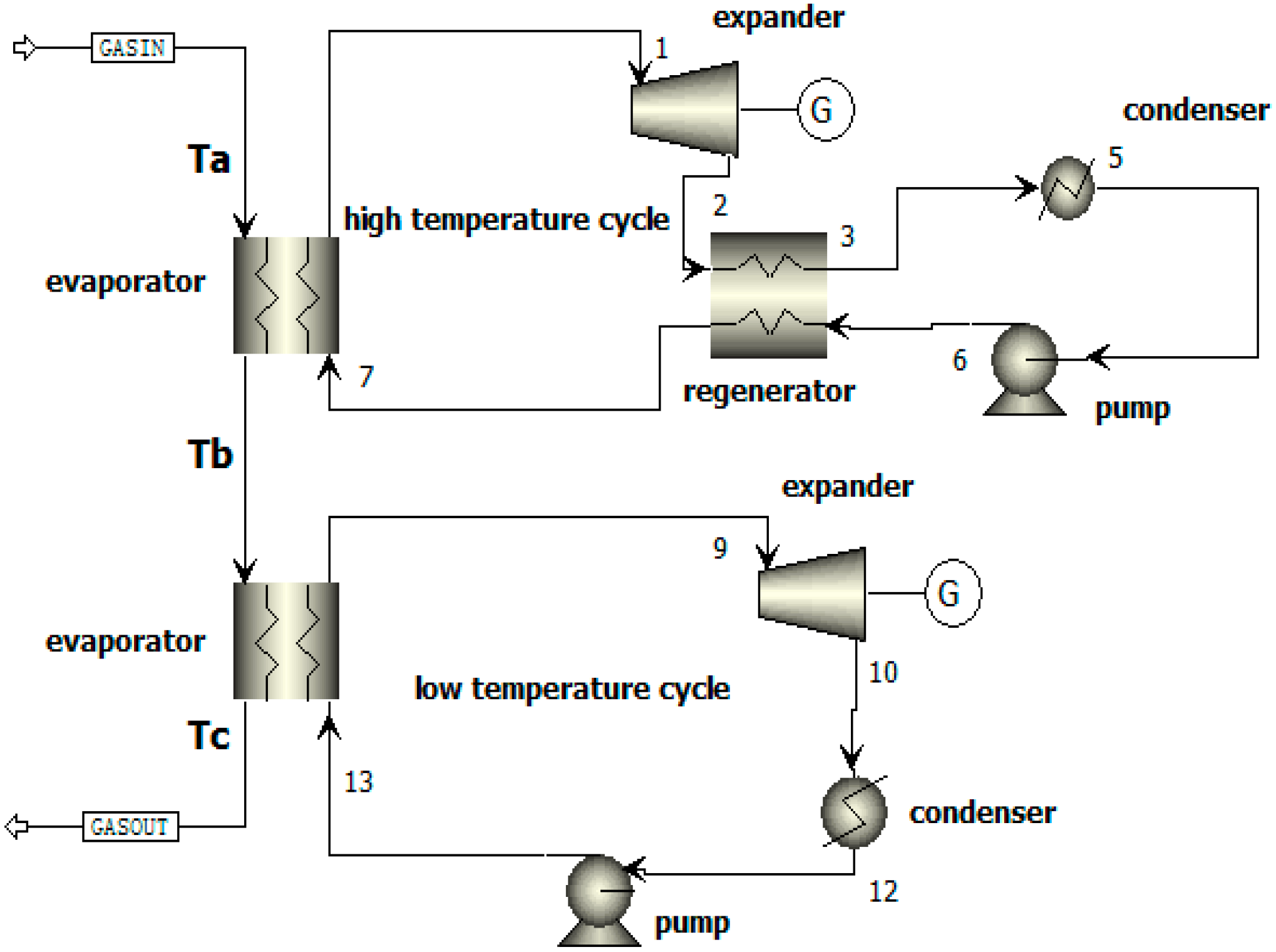
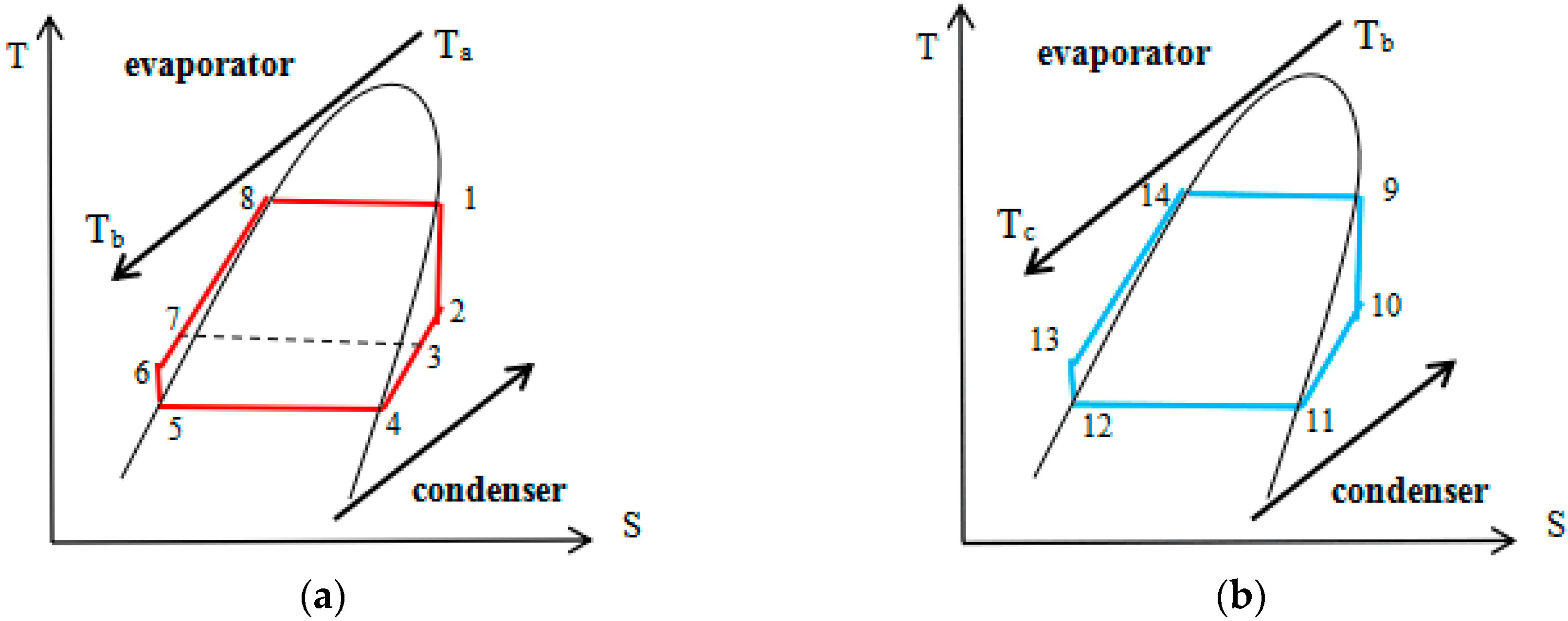
2. System Model
3. Methods
3.1. Thermodynamic Model
3.2. Calculation Conditions
- Assume that the system is stable, ignore pressure loss and heat loss in the pipeline [25];
- Both high and low temperature cycles are condensed at environment pressure (0.1 MPa);
- Select the appropriate evaporation pressure according to the thermal properties of the working fluid. The high temperature cycle evaporation pressure is set to 2.5 MPa, and the low temperature cycle evaporation pressure is set to 1.6 MPa. The thermal properties of all working fluids are calculated by REFPROP 9.0.
4. Results
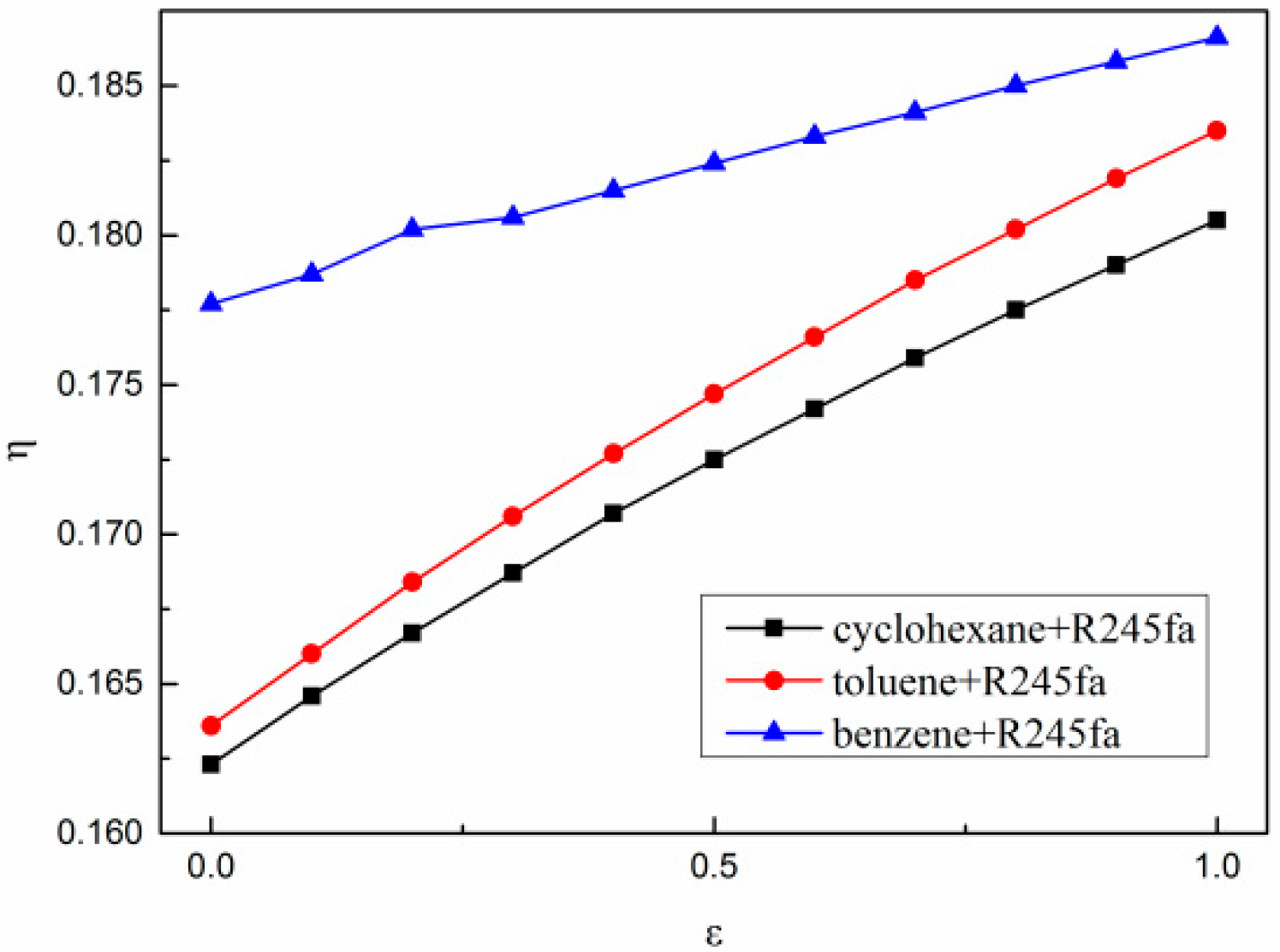
4.1. Effect of Regenerator Efficiency on Thermal Performance of Cycle
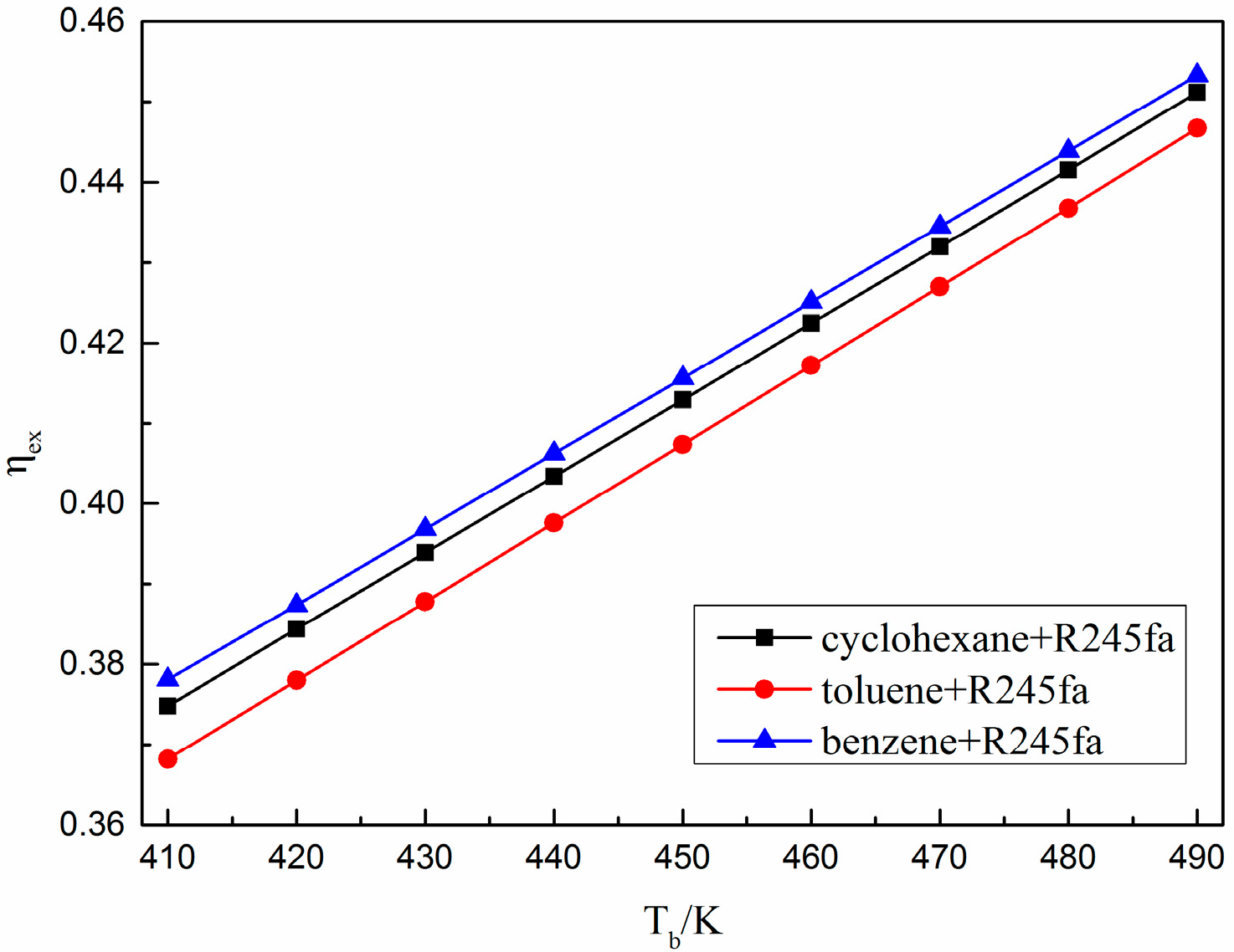
4.2. Effect of Tb on Cycle Thermal Performance
5. Conclusions
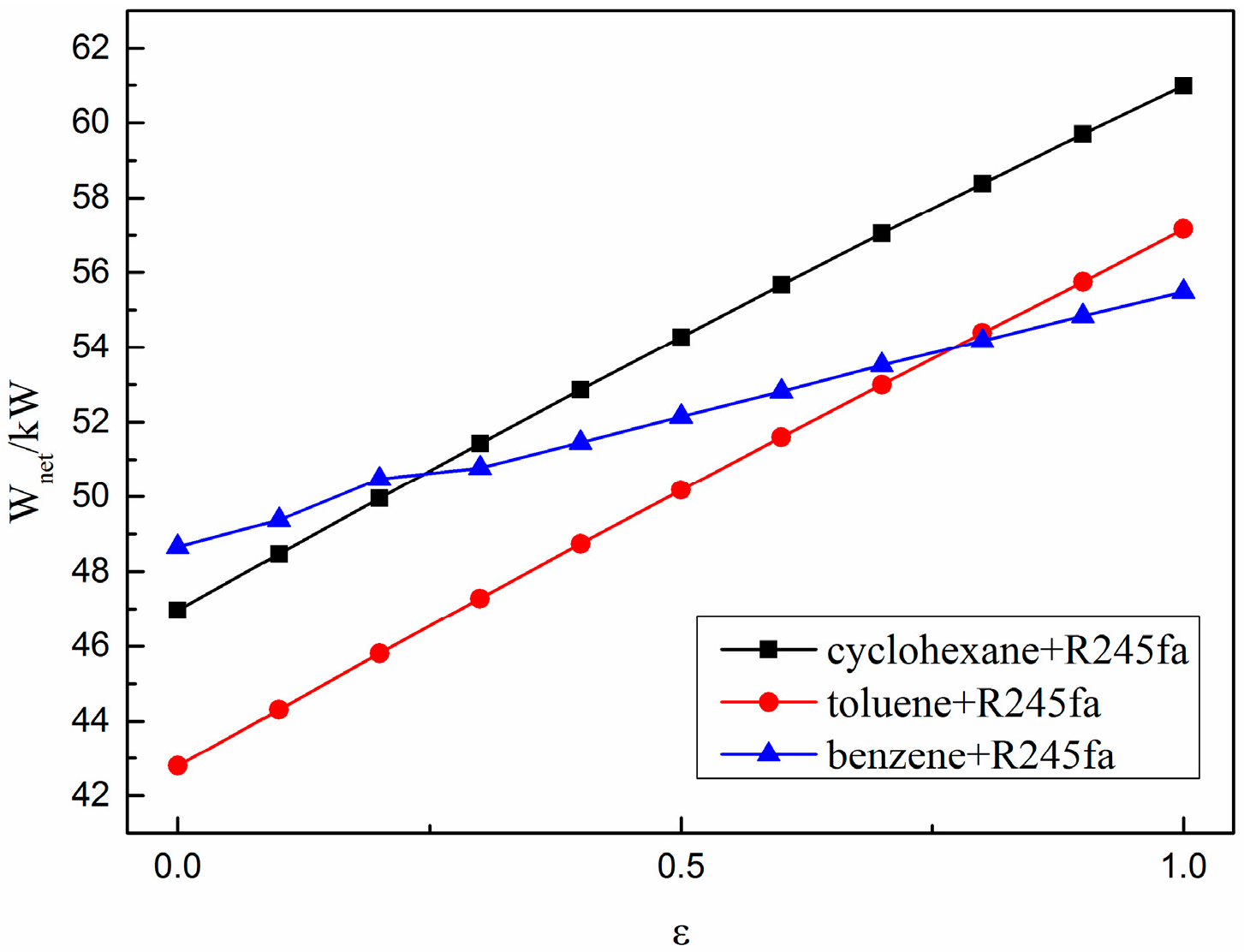
- Setting the regenerator can increase the net output power and thermal efficiency of the cycle. For the selected working fluid, when the regenerator efficiency increases from 0 to 1, the net output power of the cycle can be increased up to 14.26 kW, and the thermal efficiency can be increased up to 1.99%.
- When the primary heat exchange outlet temperature of the exhaust gas increases, the net output power and the exergy efficiency of the cycle increase. For the selected working fluid, when Tb is increased from 410 K to 490 K, the net output power of the cycle can be increased up to 10.76 kW, and the exergy efficiency can be increased up to 7.85%.
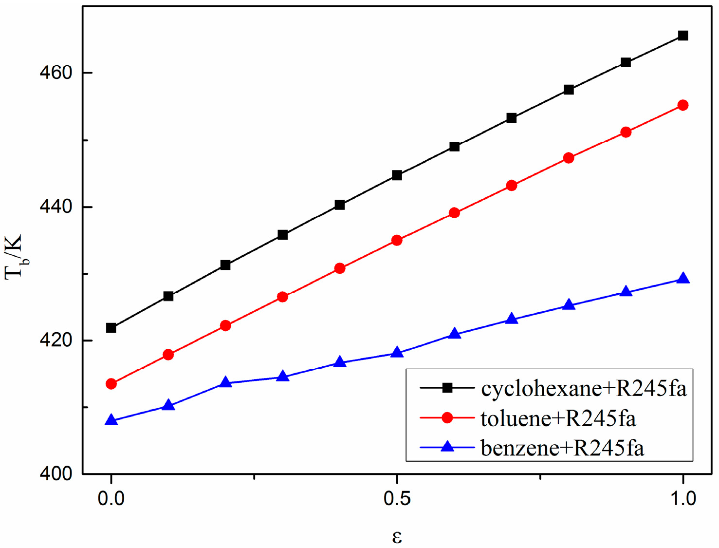
- The efficiency of the regenerator affects the primary heat exchange outlet temperature of the exhaust gas. When the efficiency of the regenerator increases, the primary heat exchange outlet temperature of the exhaust gas also increases.
Author Contributions
Funding
Acknowledgments
Conflicts of Interest
References
- Song, J.; Li, X.S.; Ren, X.D.; Gu, C.W. Performance improvement of a preheating supercritical CO2 (S-CO2) cycle based system for engine waste heat recovery. Energy Convers. Manag. 2018, 161, 225–233. [Google Scholar] [CrossRef]
- Dolz, V.; Novella, R.; García, A.; Sánchez, J.H.D. Diesel engine equipped with a bottoming Rankine cycle as a waste heat recovery system. Part 1: Study and analysis of the waste heat energy. Appl. Therm. Eng. 2012, 36, 269–278. [Google Scholar] [CrossRef]
- Endo, T.; Kawajiri, S.; Kojima, Y.; Takahashi, K.; Baba, T.; Ibaraki, S.; Takahashi, T.; Shinohara, M. Study on maximizing exergy in automotive engines. SAE Tech. Paper 2007. [Google Scholar] [CrossRef]
- Vaja, I.; Gambarotta, A. Internal combustion engine (ICE) bottoming with organic Rankine cycles (ORCs). Energy 2010, 35, 1084–1093. [Google Scholar] [CrossRef]
- Zhao, R.; Zhuge, W.; Zhang, Y.; Yin, Y.; Zhao, Y.; Chen, Z. Parametric study of a turbocompound diesel engine based on an analytical model. Energy 2016, 115, 435–445. [Google Scholar] [CrossRef]
- Larsen, U.; Pierobon, L.; Haglind, F.; Gabrielii, C. Design and optimisation of organic Rankine cycles for waste heat recovery in marine applications using the principles of natural selection. Energy 2013, 55, 803–812. [Google Scholar] [CrossRef] [Green Version]
- Teng, H.; Klaver, J.; Park, T.; Hunter, G.L.; van der Velde, B. A rankine cycle system for recovering waste heat from HD diesel engines-WHR system development. SAE Tech. Paper 2011. [Google Scholar] [CrossRef]
- Zhao, R.; Zhuge, W.; Zhang, Y.; Yang, M.; Martinez-Botas, R.; Yin, Y. Study of two-stage turbine characteristic and its influence on turbo-compound engine performance. Energy Convers. Manag. 2015, 95, 414–423. [Google Scholar] [CrossRef]
- Saidur, R.; Rezaei, M.; Muzammil, W.K.; Hassan, M.H.; Paria, S.; Hasanuzzaman, M. Technologies to recover exhaust heat from internal combustion engines. Renew. Sustain. Energy Rev. 2012, 16, 5649–5659. [Google Scholar] [CrossRef]
- Li, Y.R.; Wang, J.N.; Du, M.T. Influence of coupled pinch point temperature difference and evaporation temperature on performance of organic rankine cycle. Energy 2012, 42, 503–509. [Google Scholar] [CrossRef]
- Srinivasan, K.K.; Mago, P.J.; Krishnan, S.R. Analysis of exhaust waste heat recovery from a dual fuel low temperature combustion engine using an Organic Rankine Cycle. Energy 2010, 35, 2387–2399. [Google Scholar] [CrossRef]
- Sprouse, C.; Depcik, C. Review of organic Rankine cycles for internal combustion engine exhaust waste heat recovery. Appl. Therm. Eng. 2013, 51, 711–722. [Google Scholar] [CrossRef]
- Yang, F.; Dong, X.; Zhang, H.; Wang, Z.; Yang, K.; Zhang, J.; Wang, E.; Liu, H.; Zhao, G. Performance analysis of waste heat recovery with a dual loop organic Rankine cycle (ORC) system for diesel engine under various operating conditions. Energy Convers. Manag. 2014, 80, 243–255. [Google Scholar] [CrossRef]
- Arias Diego, A.; Shedd Timothy, A.; Jester Ryan, K. Theoretical Analysis of Waste Heat Recovery from an Internal Combustion Engine in a Hybrid Vehicle; No 2006-01-1605; SAE Technical Paper; SAE: Warrendale, PA, USA, 2006. [Google Scholar]
- Kim Young, M.; Shin Dong, G.; Kim Chang, G.; Cho Gyu, B. Single-loop organic Rankine cycles for engine waste heat recovery using both low- and high-temperature heat sources. Energy 2016, 96, 482–494. [Google Scholar]
- Shu, G.; Liu, L.; Tian, H.; Wei, H.; Liang, Y. Analysis of regenerative dual-loop organic Rankine cycles (DORCs) used in engine waste heat recovery. Energy Convers. Manag. 2013, 76, 234–243. [Google Scholar] [CrossRef]
- Yu, G.; Shu, G.; Tian, H.; Wei, H.; Liu, L. Simulation and thermodynamic analysis of a bottoming Organic Rankine Cycle (ORC) of diesel engine (DE). Energy 2013, 51, 281–290. [Google Scholar] [CrossRef]
- Wang, X.; Shu, G.; Tian, H.; Liu, P.; Jing, D.; Li, X. Dynamic analysis of the dual-loop Organic Rankine Cycle for waste heat recovery of a natural gas engine. Energy Convers. Manag. 2017, 148, 724–736. [Google Scholar] [CrossRef]
- Wang, E.H.; Zhang, H.G.; Zhao, Y.; Fan, B.Y.; Wu, Y.T.; Mu, Q.H. Performance analysis of a novel system combining a dual loop organic Rankine cycle (ORC) with a gasoline engine. Energy 2012, 43, 385–395. [Google Scholar] [CrossRef] [Green Version]
- Chen, T.; Zhuge, W.; Zhang, Y.; Zhang, L. A novel cascade organic Rankine cycle (ORC) system for waste heat recovery of truck diesel engines. Energy Convers. Manag. 2017, 138, 210–223. [Google Scholar] [CrossRef]
- Yao, B.; Yang, F.; Zhang, H.; Wang, E.; Yang, K. Analyzing the Performance of a Dual Loop Organic Rankine Cycle System for Waste Heat Recovery of a Heavy-Duty Compressed Natural Gas Engine. Energies 2014, 7, 7794–7815. [Google Scholar] [CrossRef] [Green Version]
- Huang, H.; Zhu, J.; Yan, B. Comparison of the performance of two different Dual-loop organic Rankine cycles (DORC) with nanofluid for engine waste heat recovery. Energy Convers. Manag. 2016, 126, 99–109. [Google Scholar] [CrossRef]
- Li, H.; Wang, P.; Fan, W. Performance analysis of two organic rankine cycle generation systems. Acta Energ. Sol. Sin. 2017, 38, 1667–1673. [Google Scholar]
- Song, J.; Song, Y.; Gu, C.W. Thermodynamic analysis and performance optimization of an Organic Rankine Cycle (ORC) waste heat recovery system for marine diesel engines. Energy 2015, 82, 976–985. [Google Scholar] [CrossRef]
- Wang, H.; Liu, W. Structure Size and Isentropic Efficiency of Single-Stage Radial Turbine Based on Organic Rankine Cycle. J. Tianjin Univ. Sci. Technol. 2014, 47, 1088–1094. [Google Scholar]
- Shao, L.; Zhu, J.; Meng, X.; Wei, X.; Ma, X. Experimental study of an organic Rankine cycle system with radial inflow turbine and R123. Appl. Therm. Eng. 2017, 124, 940–947. [Google Scholar] [CrossRef] [Green Version]
- Dong, X.; Yang, F.; Zhang, H. Performance Analysis of a Dual Loop Rankine Cycle for Vehicle Diesel Engine under Various Operating Conditions. Trans. Beijing Inst. Technol. 2015, 35, 471–476. [Google Scholar]
- Song, J.; Gu, C.W. Parametric analysis of a dual loop Organic Rankine Cycle (ORC) system for engine waste heat recovery. Energy Convers. Manag. 2015, 105, 995–1005. [Google Scholar] [CrossRef]


| Parameter | Value |
|---|---|
| Displacement | 13 L |
| Maximum torque | 2500 N·m |
| Exhaust gas mass flow | 0.75 kg/s |
| Rated power//Rotation speed | 412 kW/2100 rpm |
| Exhaust gas temperature | 653 K |
| Composition | Molecular Weight (g/mol) | Fraction |
|---|---|---|
| O2 | 32.00 | 0.1483 |
| CO2 | 44.00 | 0.0436 |
| N2 | 18.01 | 0.0620 |
| H2O | 28.01 | 0.7461 |
| Working Fluid | Tcr (K) | Pcr (MPa) | Molecular Weight (g/mol) | GWP | ODP |
|---|---|---|---|---|---|
| toluene | 591.75 | 4.126 | 92.138 | Very low | 0 |
| benzene | 562.02 | 4.906 | 78.112 | Very low | 0 |
| cyclohexane | 553.64 | 4.075 | 84.161 | Very low | 0 |
| R245fa | 427.16 | 3.651 | 134.05 | 950 | 0 |
© 2018 by the authors. Licensee MDPI, Basel, Switzerland. This article is an open access article distributed under the terms and conditions of the Creative Commons Attribution (CC BY) license (http://creativecommons.org/licenses/by/4.0/).
Share and Cite
Li, X.; Liu, T.; Chen, L. Thermodynamic Performance Analysis of an Improved Two-Stage Organic Rankine Cycle. Energies 2018, 11, 2864. https://doi.org/10.3390/en11112864
Li X, Liu T, Chen L. Thermodynamic Performance Analysis of an Improved Two-Stage Organic Rankine Cycle. Energies. 2018; 11(11):2864. https://doi.org/10.3390/en11112864
Chicago/Turabian StyleLi, Xinyu, Tao Liu, and Lin Chen. 2018. "Thermodynamic Performance Analysis of an Improved Two-Stage Organic Rankine Cycle" Energies 11, no. 11: 2864. https://doi.org/10.3390/en11112864