1. Introduction
Modular multilevel converters are coming solutions for providing high reliability, capability and good harmonic performance solution for power electronic converters [
1,
2]. MMCs are generally used in high-power applications such as grid-connected converters [
3]. They consist of a high number of capacitors and power electronic switches. Accordingly, the MMC absorbs a small amount of active power to keep the capacitors’ DC voltage constant and compensate for power losses. However, a mismatch in conduction and the switching losses of power electronic switches, make the voltage of the capacitor unbalance. Balancing the voltages has been a major issue in the latest research [
4,
5,
6,
7]. Moreover, there have been investigations concerning the implementation of the advanced current controller for MMC. In Reference [
8], a model predictive control strategy is proposed to regulate the AC side current, balance the capacitor voltages and control of circulating current concurrently using a single modified cost function. Another study in Reference [
9] has proposed a design which controls the total energy and energy balancing between upper and lower arms. A method in Reference [
10] for computing the circulating current reference by Lagrange-based multi-objective optimization has been introduced. This method is compared with the closed-loop methods and has proven better performance. In Reference [
11], an algorithm for mitigation of circulating current is presented, in which shows that it is composed of negative sequence with double line frequency and DC component. Also, the hysteresis current control algorithms can be used to control MMC [
12]. Recently in Reference [
13], a novel control strategy has been proposed for MMC based on differential flatness theory, in which instantaneous active and reactive power values are considered as the flat outputs. To achieve this goal, a mathematical model of the MMC taking into account dynamics of the ac-side current and the dc-side voltage of the converter is derived in a d-q reference frame. Moreover, in Reference [
14] presents a new function-based modulation control method for modular multilevel converters (MMCs). The main contribution of this study is the formulation of two new modulation functions for the required switching signals of the MMC’s upper and lower sub-modules, correspondingly. Furthermore, the stability analysis and control techniques for grid connected converter based on MMC is discussed in Reference [
15]. In all above-mentioned literature, there is not a comprehensive model of MMC which could be considered for evaluation of MMC during unbalanced voltage conditions.
Moreover, dynamic operation and the control of Grid Connected-MMC (GC-MMC) under unbalanced grid voltage faults have not been referred in detail. Therefore, it seems essential to address the behaviour of this operation topology under different voltage disturbances in distribution power systems. Unsymmetrical condition on the grid voltages and its negative component sequence appears double supply frequency component in the DC-link voltage and consequently the third harmonic component on the AC side. Then it is a basis for flowing large negative-sequence current through the MMC; this may the grid connected-MMC lose its operation. Accordingly, the output voltages of the MMC are controlled to minimize the negative-sequence current flowing into the converter and it makes unbalance reduction on the grid voltages.
In this paper, a dynamic nonlinear model of a modular multilevel converter is developed. In the proposed model, symmetrical elements of voltage and current considering positive and negative sequences are involved. Then, because of the existing unbalance voltage conditions and uncertainties in the model, a robust adaptive current controller is developed for GC-MMC which includes a sliding mode and fuzzy controllers. In addition, the robustness and stability of the controllers have been proved by Lyapunov theory and completely guaranteed. Finally, to justify the potentiality of the recommended control strategy, a simulation study is fulfilled and the obtained results for normal and unbalanced fault conditions are presented.
This paper is categorized as follows:
Section 2 presents the modelling of GC-MMC. Then the proposed control scheme is given in
Section 3. Finally, in
Section 4, simulation results are presented with extra detail.
3. Fuzzy-Sliding Mode Control (FSMC) of GC-MMC
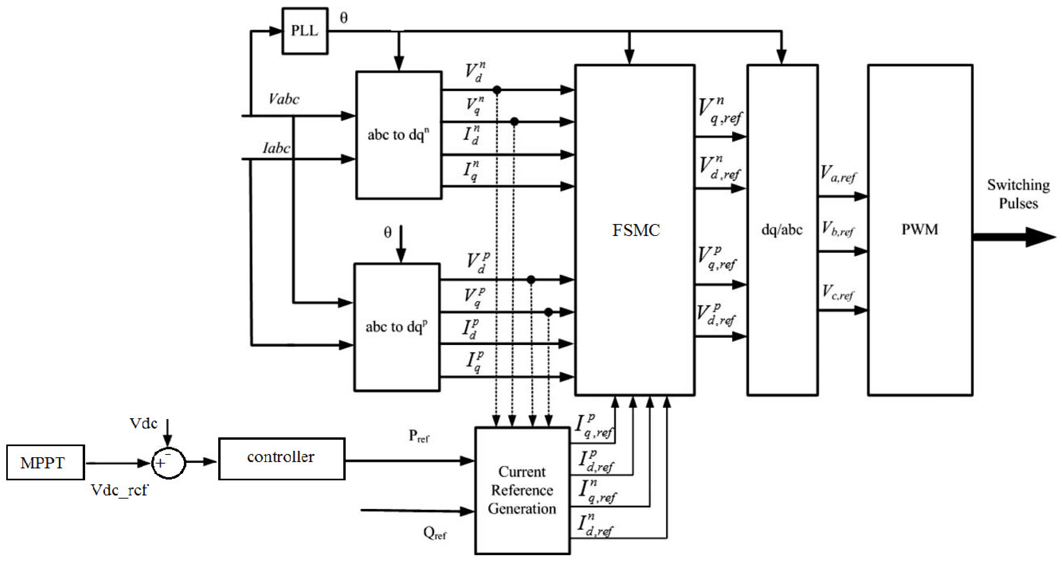
A block chart of the proposed control strategy for PV system is illustrated in
Figure 2. The upper and lower arms of the MMC principally perform as controlled voltage sources and they are modulated using Pulse-Width Modulation (PWM) technique. The PWM method employed in this study is basically a carrier based Level-Shifted PWM strategy [
14]. In
Figure 1, the Maximum Power Point Tracker (MPPT) module which provides the voltage or current reference is utilized, where
Vdc-ref is the reference dc-link voltage and
Vdc is the actual dc-link voltage. The PV array’s voltage is remained close to a reference dc-link voltage. Then, the power control is implemented. To achieve this goal, current control strategy based on fuzzy sliding mode control is established. The details of suggested current controller are explained as follow.
Equation (1) is a nonlinear system with the presence of parameters uncertainties and external voltage disturbances. Generally, the state space equation of the nonlinear system including uncertainties is written as follows [
16]:
where
X(
t) is the state vector;
u(
t) is the control input of system (1); ∆
g expresses uncertainty part of the system (1) on
R and
L values;
d(
t) is the disturbance of the system (1) where it is considered as grid voltage variation here.
Moreover, the uncertain and disturbance parts of the nonlinear model are assumed to be bounded that is,
where
δ and
ε are two positive and known constraints, which mean the margins for the uncertain and disturbance parts.
The complexity of non-linear Equation (1) and demand for fast response during power tracking leads to an adaptive fuzzy sliding mode control structure which is proposed for designing current controllers of the GC-MMC. Sliding mode control (SMC) is one of the control methods used for current regulation in power electronic converters. However, the basic problem of employing SMC is chattering. Many different methods have been suggested to deal with this problem in SMC [
17]. Recently a combination of fuzzy control and SMC has been employed for this purpose and the results are found to be effective [
18,
19].
When the fuzzy sliding control strategy is being designed to regulate converter’s output currents, the current tracking error is, firstly, defined for positive and negative sequence components as follows:
where
idp_ref,
iqp_ref,
idn_ref and
iqp_ref are reference currents of symmetrical
dq components, respectively.
Secondly, a modified sorting method is used for stabilizing of SM capacitor voltage. Commonly, after modulation, the number of SMs should be activated or deactivated. Being so, the sorting algorithm is implemented to balance the capacitor voltages. On that account, the voltage error between SM capacitor voltages and their references takes a step forward, which results in minimum voltage error. It is considered as another error tracking signal. The voltage errors are calculated by:
where
Vc,ref is the reference SM capacitor voltage.
The estimated capacitor voltage
Vc,j for each SM is obtained by the formula below:
where
ik,j is arm current and
Ts is the control time period.
Regarding the above equations, the error vector could be formed as follow.
Then the time-varying sliding surface for first order system is proposed [
14]:
where
λ is a strict positive parameter and it is tuned based on the system bandwidth.
For grid-connected converters applications, the faults in grid voltage and uncertainties on output filter parameters are unknown and the control signal is designed by satisfying
ds/
dt = 0 as follow:
where the
Xref is a vector which it is included the reference values for state variables.
In the traditional SMC, the control signal based on Lyapunov stability theory is defined as follows:
where
kw is the switching gain.
The chattering phenomenon is the inherent challenge of SMC which is made by sign function on the overall control signal
u. Hence, the fuzzy-sliding mode control is proposed to eliminate the chattering problem in current control loops of GC-MMC. By implementing this method, the robustness of the controller is satisfied. Also, the performance of the system is improved since the chattering has been eliminated. Consequently, the control signal of fuzzy-sliding mode controller could be written as follows:
In fact, in the proposed current controller, there is a fuzzy controller for each symmetrical component of
dq sequences that has two inputs (
) including one output (
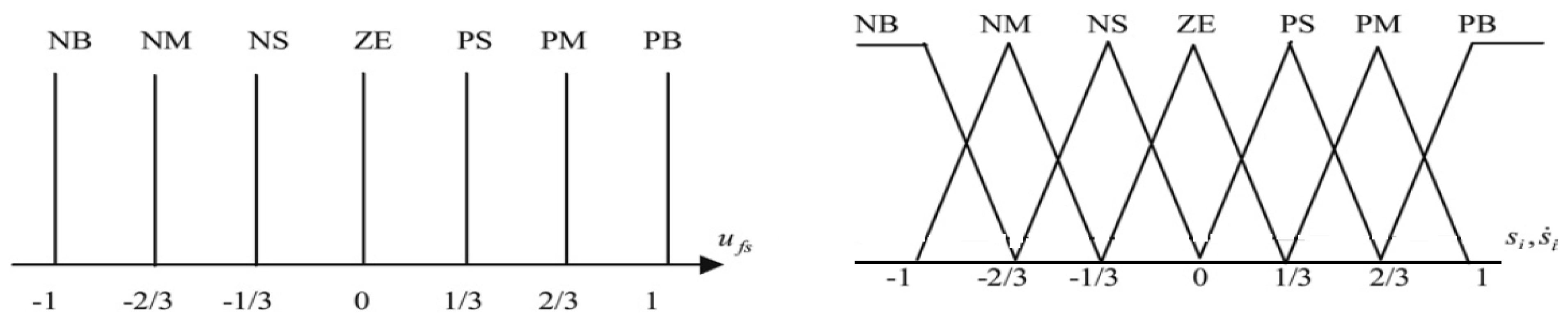
u). There are also seven linguistic variables, NB (Negative Big), NM (Negative Medium), NS (Negative Small), ZE (Zero), PS (Positive Small), PM (Positive Medium), PB (Positive Big), which are used as inputs and outputs respectively. Furthermore, to procure appropriate dynamic response, achieve a high level of accuracy and guarantee the stability of the whole system, a set of decision rules for the fuzzy controller is designed that is presented in
Table 1. These rules contain the input/output relationships which they are mapped by membership functions to describe the control strategy. Both input and output membership functions are scaled into the range of −1 and 1 with an equal span as shown in
Figure 3. In order to guarantee the robustness and stability of the controller, an adaptive procedure based on Lyapunov theory is implemented which is completely given in Reference [
19,
20].
4. Simulation Results and Analysis
The complete modelling of MMC is carried out in MATLAB/Simulink software to look into the performance of robust non-linear control strategy. The nominal parameters of the power converter and controller are presented in
Table 2.
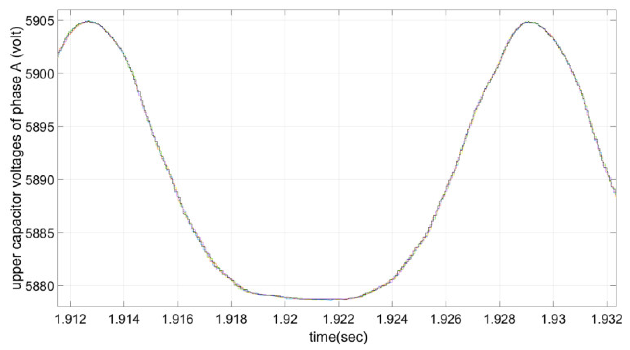
The reference values for the real power and reactive power are determined and implemented. The voltages of six capacitors of phase A are illustrated in
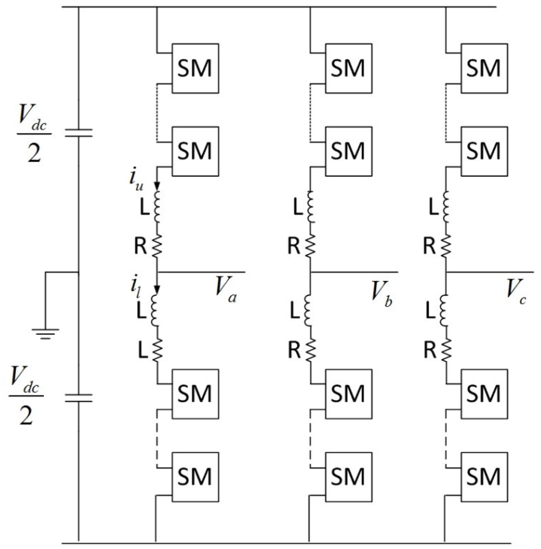
Figure 4. As shown, they are around the nominal value of each SM capacitor initial voltage. The three-phase line to line voltages are given in
Figure 5. Six levels of voltage are clearly seen as expected. It is obvious that the voltage levels vary within acceptable boundaries caused by charging and discharging of the capacitors.
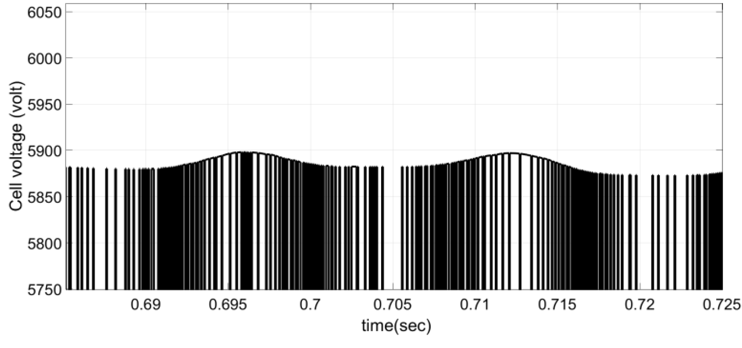
In
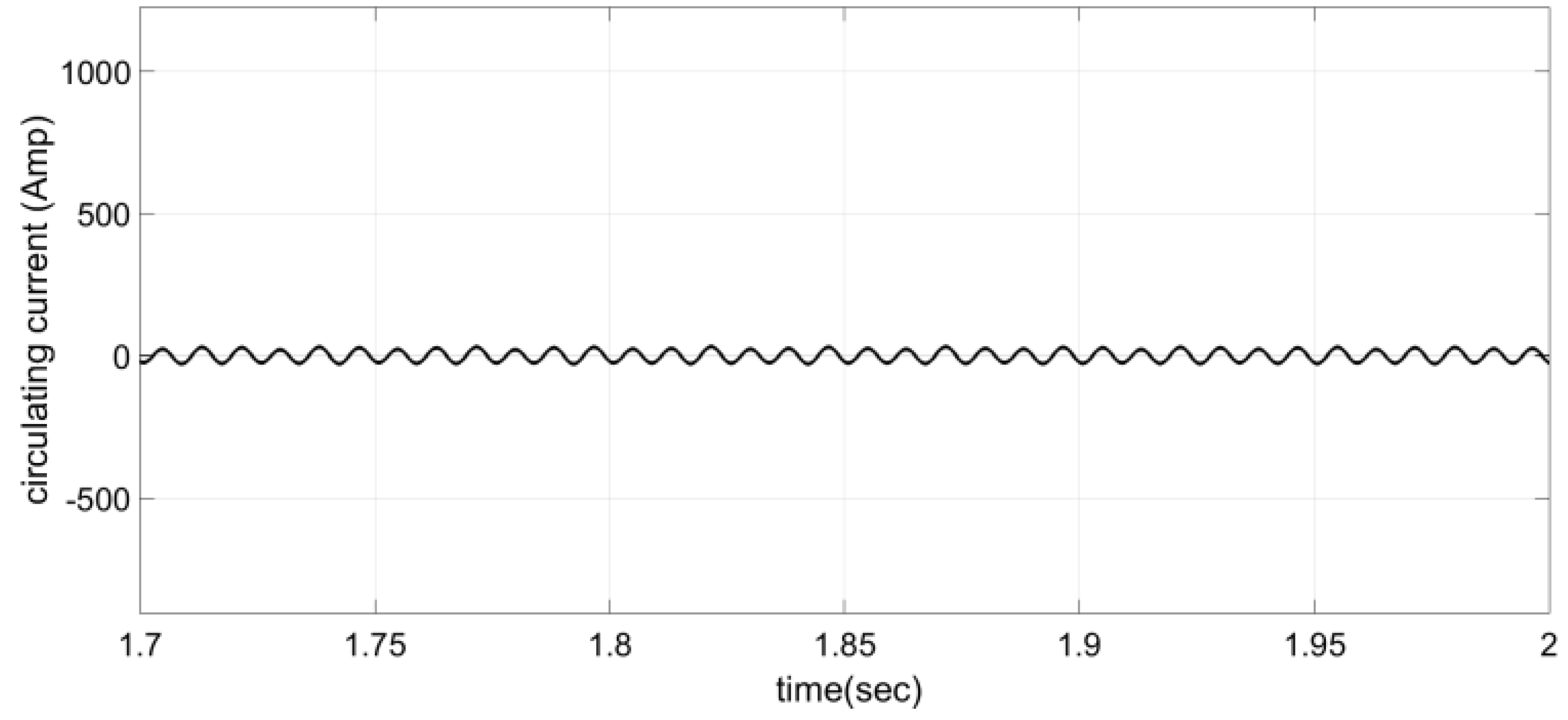
Figure 6, the upper cell voltage of phase A is displayed. Because of 10 times switching of cell voltage in a cycle, the switching frequency of approximately 600 Hz is clearly observed for the power electronic switch. The dc current flowing which circulates through the arms and the dc side of the converter is illustrated in
Figure 7. The DC current supports the power balance in the dc side’s capacitors.
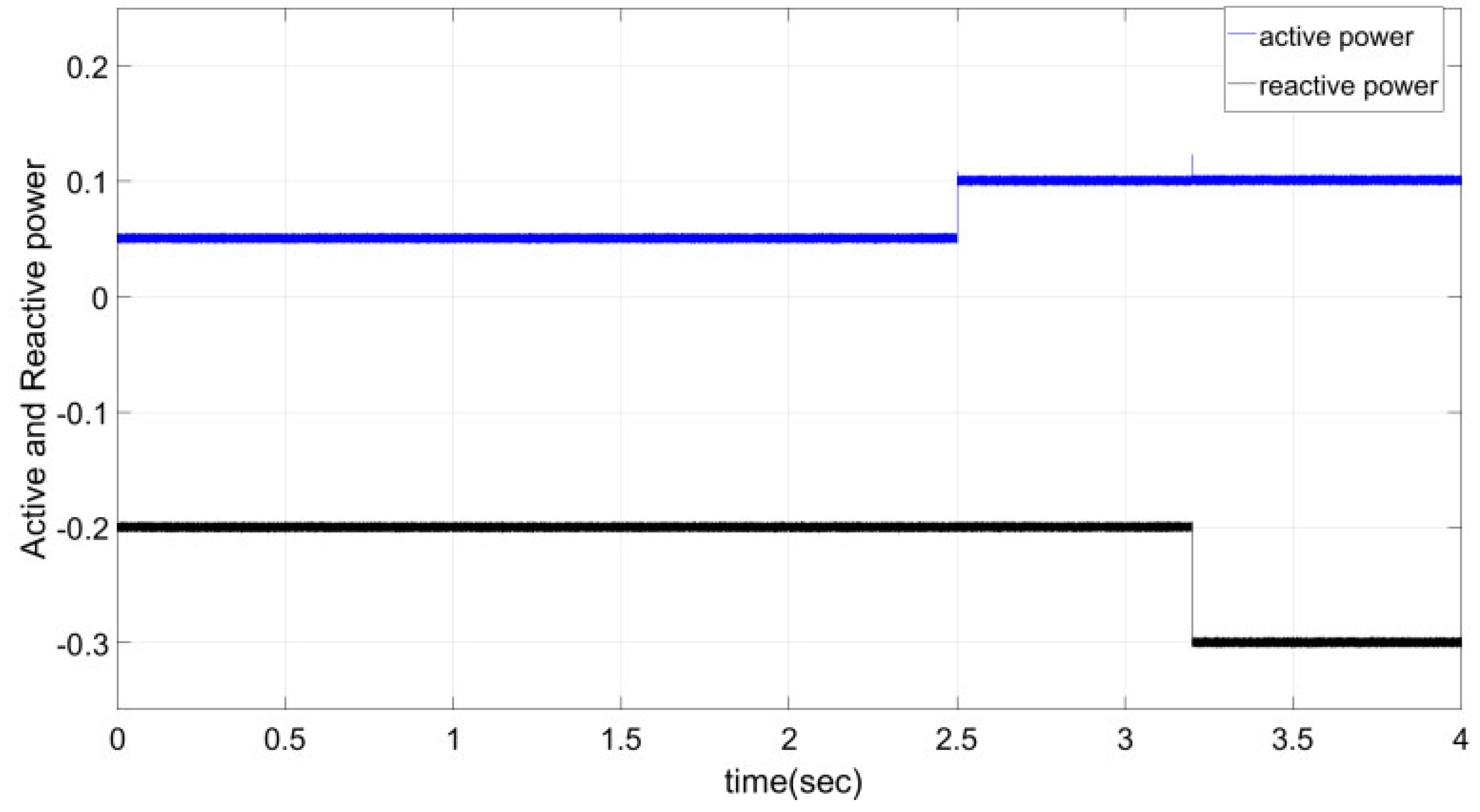
Figure 8 illustrates how the GC-MMC replies to the requested active power at 2.5 s and 3.2 s of the reactive power. In this case, active power changes to 0.1 MW and reactive power goes up to 0.3 MVAr. It shows a corresponding variation in the exchanged active and reactive powers. There is also an enhancement in the response of steady-state and transient conditions when implementing the proposed controller.
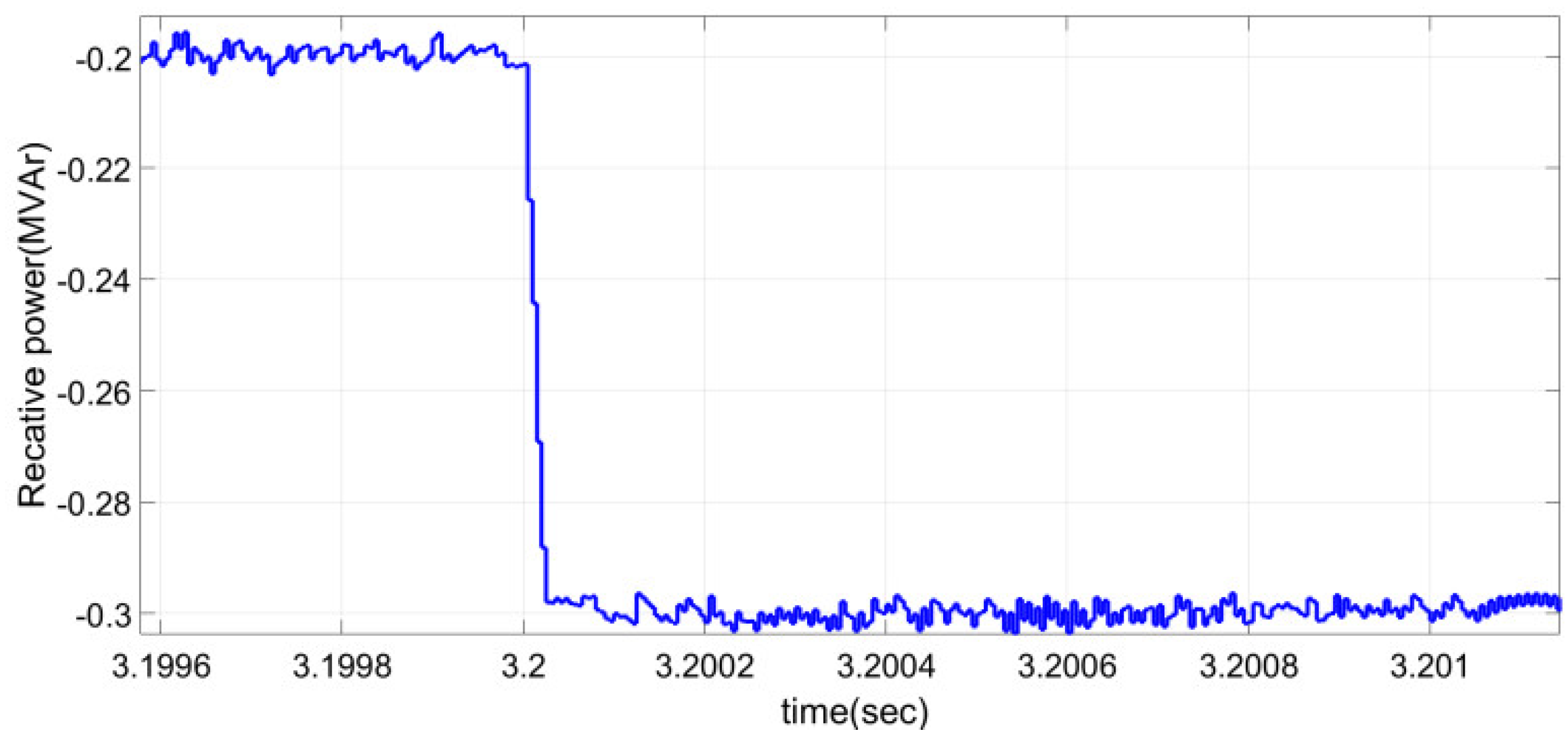
Moreover, to prove the robustness of the proposed controller, the inconsistency of output filter parameters is considered for
R and
L. Accordingly, the 1.1
R and 0.9
L are implemented in simulation models based on the nominal value in
Table 1. In this case, the simulation is run alike the prior conditions. In
Figure 9, the reactive power tracking of the proposed controller is presented due to the mismatches. It proves the robustness of the proposed controller during the changing of filter parameters. Also, it shows that fuzzy-sliding mode controller is not sensitive to plant uncertainties.
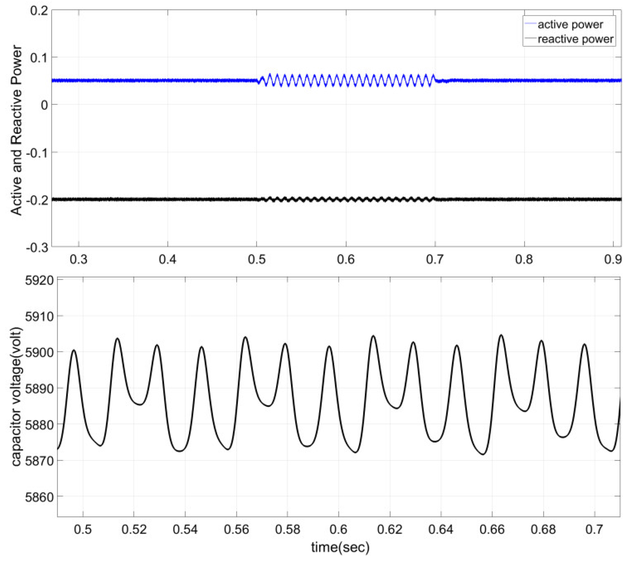
Further evaluation of the proposed controller is carried out during grid voltage disturbance. In phase, A, voltage sag is considered to drop 20%. Regarding the unbalanced voltage fault, there are oscillations in active and reactive powers which are illustrated in
Figure 10. These oscillations are related to the proposed current control strategy and it makes the oscillating on active and reactive powers. Finally, as it has been demonstrated, the capacitor voltages vary within acceptable limits and are not influenced by grid voltage faults.
In order to compare the fuzzy-sliding mode control with PI controller, some simulation tests were performed on MMC during unbalance voltage conditions. The design of PI is primarily based on a trial and error procedure. But during designing of fuzzy-sliding mode control, the triangular membership was considered because of its simplicity of implementation and because less computational intensity is required. The number of linguistic variables and the base width of linguistic variables have some effect on the response time and magnitude of ripple in the output voltage. However, they do not seriously affect the response as the change of gains in a PI controller does. In the design of the PI-controller, the gain selection is crucial. A set of gains can be ideal for one type of disturbance but not for another type of disturbance. The gains were selected to provide a performance compromise for supply voltage disturbance and load disturbance. Digital implementation at the sampling rate of 20 kHz was considered for all these controllers.
5. Experimental Results
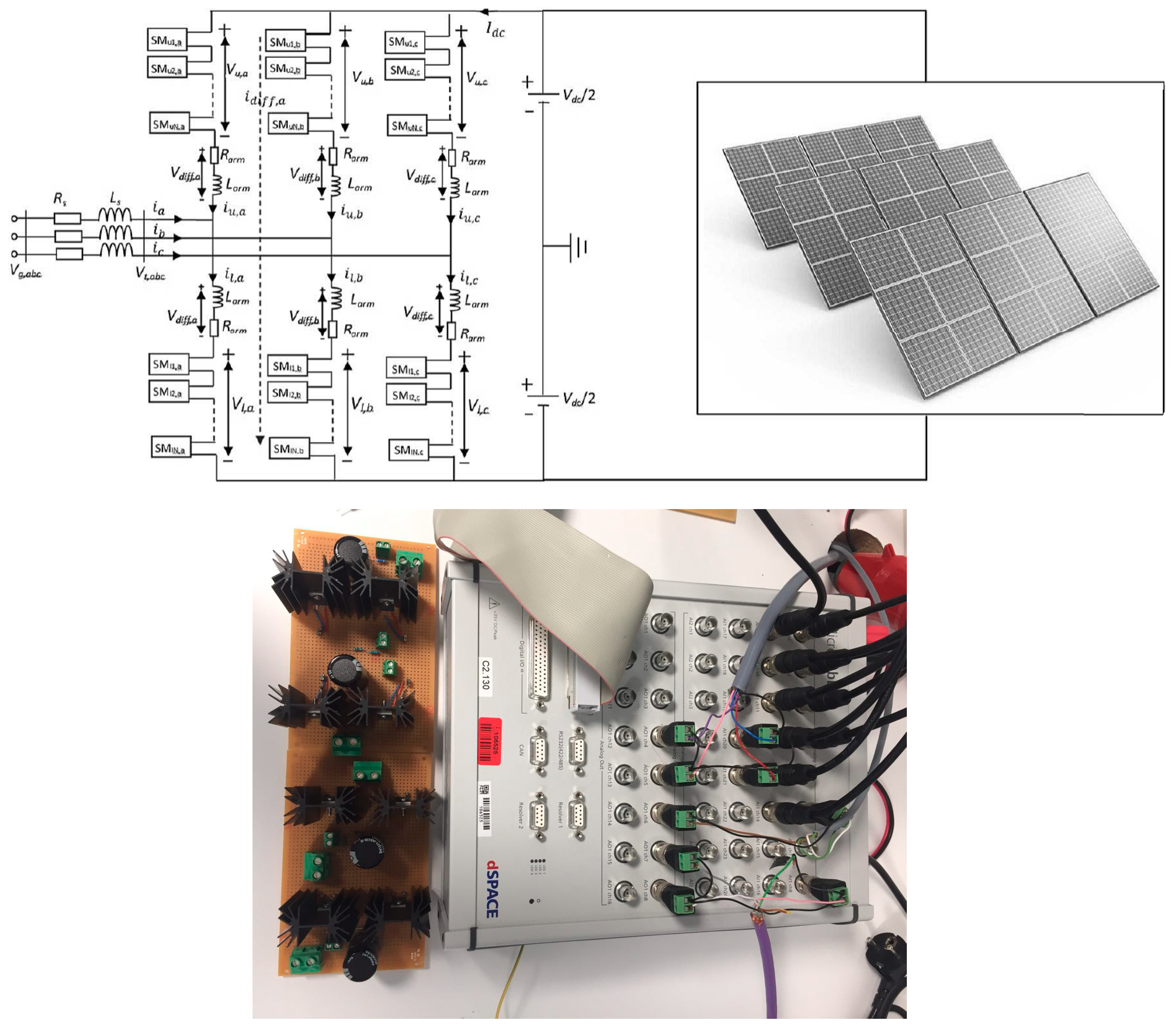
To examine the performance of the proposed controller, an experimental setup has been developed. The test system is connected to 750 W rooftop solar system. Since the system required many input/outputs and sampling frequency up to 10 kHz, the dSPACE MicroLabBox was decided to be used as the real-time interface for control of the MMC. The structure of the test setup is shown in
Figure 11. The experimental setup is of a low power, 3 levels, single phase MMC, as shown in
Figure 11. In the laboratory, MPPT module is used to regulate the output voltage of PV panels. The parameters for the experimental setup are listed in
Table 3.
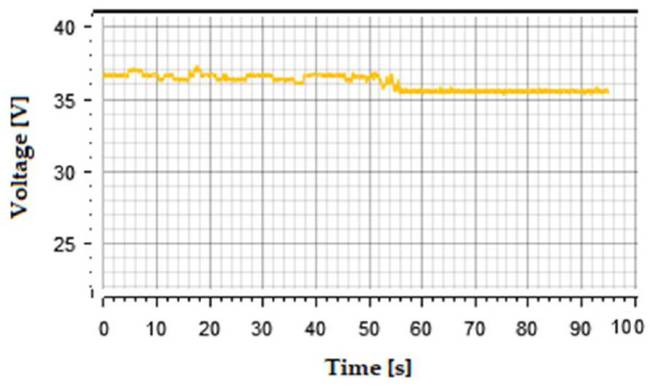
The experimental results only show the dynamic tracking properties of the proposed controller. The profile given to it was of 6 A current for the first 50 s and then it was increased to 9 A thereafter. In the test setup, the input voltage at MPP is around 29 V. The rms output voltage is illustrated in
Figure 12. It is principally constant as the dc-link voltage should. The voltage across the capacitor of module 1 as obtained on the control desk can be seen in
Figure 13. As the voltage was obtained at 𝑣
dc ≈ 20 V, it is expected the average value across any submodule at any given time, when the sorting algorithm is active, should be approximately 10.
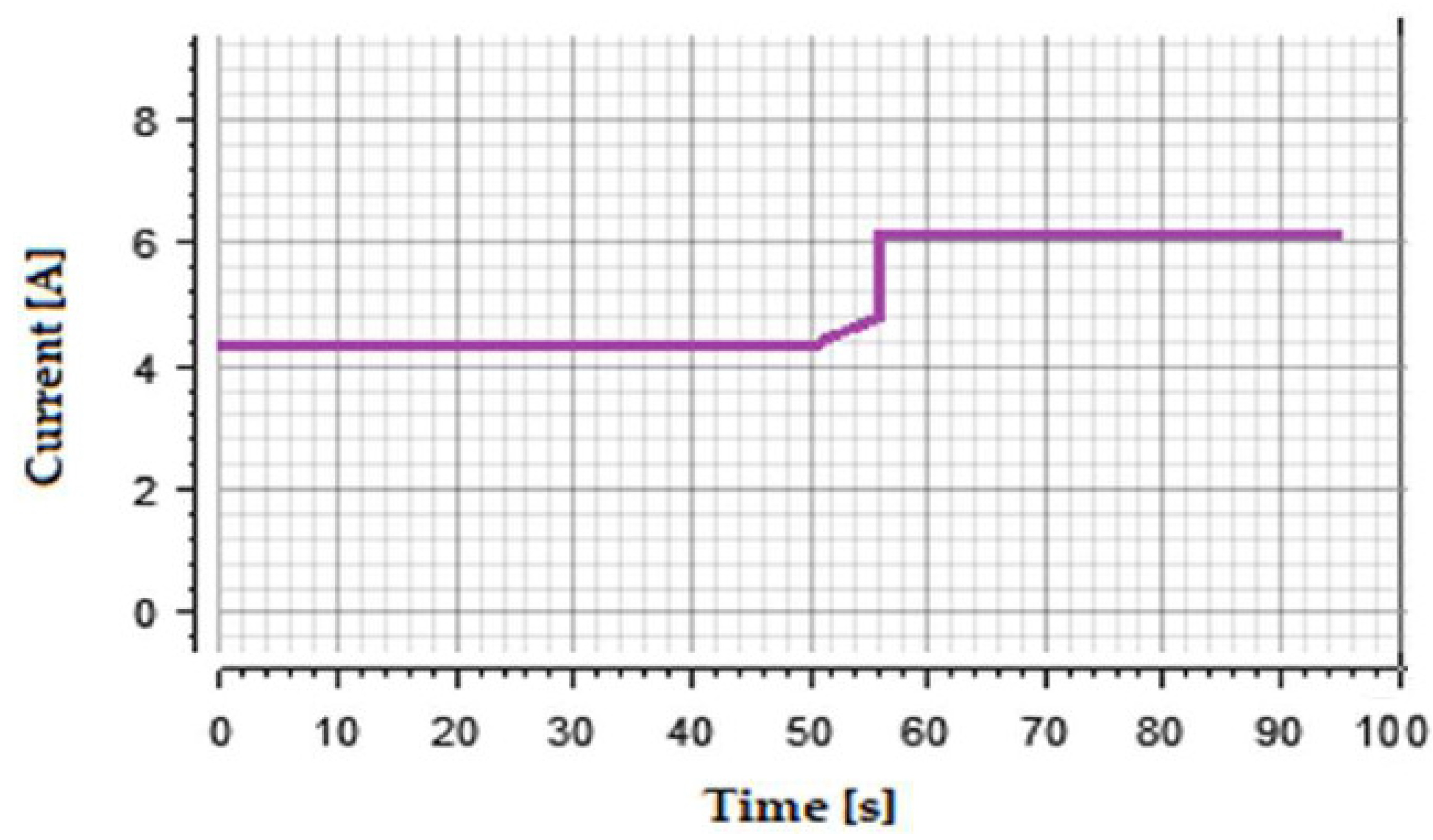
To survey the robustness of the proposed controller, the real value of arm inductance changes to 5.6 mH. The power supply was operated in a constant current mode, to emulate a PV module at a constant temperature but different insolation.
Figure 14 shows the input current waveform.
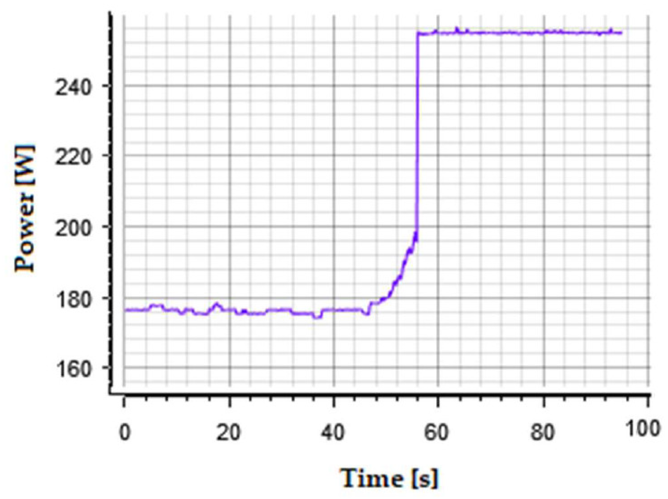
The change in input current is only reflected as a change in output power which is illustrated in
Figure 15. As depicted, the proposed controller properly follows the reference value and its dynamic performance is satisfied. By comparison between the simulation and experimental results, it is achieved the offered control strategy is able to overcome the parameter mismatches in the output filter. The dynamic performance is guaranteed during changing the demanded power. The dynamic performance is the trade-off between the
kfc and the number of rule bases during designing of the fuzzy controller and it influences on both simulation and experimental results. From the simulation result, it is evident that the controller is capable to reduce the impact of the external events such as asymmetric grid voltage fault and it is very important during connection of photovoltaic systems to weak grid. From the simulation results, it can be observed that the proposed current controllers let retaining power as requested by the DC current source during and after the event. Despite the unbalance of AC voltages, the AC current controller can balance the resulting AC currents. As a result, the active as well as reactive powers start oscillating with double frequency of AC grid. Thanks to the developed current controller, the applied event is damped by the stored energy inside the MMC and consequently does not disturb the DC current and voltage.
6. Conclusions
This paper presents the fuzzy sliding mode current control strategy for GC-MMC configuration. Considering the unbalance voltage conditions and complexity of the model including a high number of state variables and parameters uncertainties, a robust adaptive current control structure using sliding mode control and fuzzy control, is developed for GC-MMC. The proposed control makes a proper performance for MMC and enables separate control of the symmetrical elements of grid currents. The simulation and experimental results suggest that the proposed controller is very robust during the changing of filter parameters. The dynamic response, also, proves that the fuzzy sliding mode controller is not sensitive to plant uncertainties and adequate dynamic response. Moreover, based on the proposed controller, the capacitor voltages fluctuate within acceptable limits and they are not influenced by grid voltage faults. In the simulation results, in phase, A, voltage sag is considered to drop 20%. From the simulation results, it can be observed that the proposed current controllers let retaining power as requested by the DC current source during and after the event. Moreover, it is obtained from the experimental results by changing 12% of real value of inductor in output filter; the current controller could overcome the parameter mismatch inside the MMC.


