Characteristics Analysis of Doubly Fed Magnetic Geared Motor Considering Winding Frequency Conditions


Mechatronics System Research Lab., Department of Electrical Engineering, Dong-A University, Saha-gu, Busan 49315, Korea
*
Author to whom correspondence should be addressed.
Energies 2018, 11(10), 2564; https://doi.org/10.3390/en11102564
Submission received: 28 August 2018
/
Revised: 12 September 2018
/
Accepted: 20 September 2018
/
Published: 26 September 2018
Abstract
:The magnetic geared motor, which has improved torque density because of the magnetic gearing effect, has been researched. However, its narrow operating region due to the operating mechanism by the magnetic gearing effect and field flux by the PM is a challenge that needs to be overcome. Whereas, the doubly fed magnetic geared motor (DFMGM) can extend the operating region because of the double stator and double winding structure with the individual frequency control of the current fed to the inner and outer windings. However, two rotating magnetic fields, which are produced by the inner and outer winding flux, exist at the air-gap, and the large numbers of space harmonic components of the modulated flux density are produced at the air-gaps. These space harmonic components, which are produced by the winding MMF, influence not only the back-EMF of the winding but also the performances of the operating torque. Besides, the inner and outer windings affect each other in the back-EMF, and its characteristics appears differently in the inner and outer windings. Thus, in this paper, the structure, operating strategy, and basic characteristics according to the frequency condition in the inner and outer windings are presented.
1. Introduction
Due to the exhaustion of the fossil fuel and the environmental pollution, efforts to replace the internal combustion engine (ICE) vehicle have continued. Electric vehicles (EVs) with zero carbon dioxide emission have been studied as an alternative to the ICE vehicle. It is important that the traction motor in EV should satisfy the design requirements such as the compactness, high torque density, high efficiency, and wide operating range, due to the constraints in space to accommodate components including the inverter unit, power converters, battery, and gear box. Hence, the permanent magnet synchronous motor (PMSM) using rare-earth magnet has received much attention thanks to its high torque density [1,2]. However, problems like uncertainty in the availability and high price of the rare-earth magnet bring the challenge of introducing these machines for high end applications. As a result, recently the attention has shifted towards machine with no or less permanent magnet (PM) volume. Furthermore, in the traction motor that has the permanent magnet rotor, the field-weakening region is much narrower than that of the motors with the capability of adjusting the field flux by regulating the field current. Because of these problems, the traction motors, which do not include the PM, such as DC biased switched reluctance motor, wound field flux switching motor, and sinusoidal reluctance motor, have been studied as alternatives to PMSM [3,4].
In the direct drive applications including the in-wheel motor for EVs, papers with respect to the magnetic geared motor, which has the improved torque density by the magnetic gearing effect, have been published [5,6,7]. As shown in Figure 1a, the magnetic geared motor consists of the 3-phase AC winding (armature winding), modulating pieces, and the PM rotor. Unlike the synchronous motors having the same pole number to each other in the armature winding and the PM rotor, the magnetic geared motor has different pole numbers in the armature winding and the PM rotor. In general, the armature winding of the magnetic geared motor has a smaller pole number than that of PM rotor so that the output torque is increased, and the output speed is decreased. In other words, the output rotor in the magnetic geared motor is operated at a reduced speed and increased torque by the gear-ratio between the numbers of the poles of the armature winding and the PM rotor, and it is the most different part about the general synchronous PM machines. This speed reduction and torque increase can be obtained from the magnetic field modulation by the modulating pieces, which is called the magnetic gearing effect or Vernier effect. The magnetic field produced by the armature winding MMF is modulated by the modulating pieces, and the space harmonic components of the modulated magnetic field consist of the working harmonic, which synchronizes with the PM rotor, and the other space harmonics. Thus, naturally, the number of poles of the PM rotor should be determined in the same way as the working harmonic and not by the number of poles of armature winding.
In general, the magnetic geared motor has been researched in the low-speed, high-torque applications because of the reduced speed by the magnetic gearing effect and the narrow field-weakening region caused by the PM field flux. However, if the PM rotor is replaced with the 3-phase winding and the modulating pieces are used as the output rotor, the operating region can be significantly extended. As shown in Figure 1b, the doubly fed magnetic geared motor (DFMGM) has the 3-phase AC winding in the outer stator instead of the PM rotor, and the rotating flux plays a role in the field flux [8,9]. Thus, the output speed can be increased from the output speed by the inner winding flux to as much as the increment of the frequency of the outer winding flux. In other words, the output speed is determined by both the frequencies of inner and outer winding flux, and the equation for these frequencies and the output speed is defined by the magnetic gearing effect. In addition, the DFMGM can eliminate the problems caused by the rare-earth magnet such as the unstable supply and price of the magnets. However, the drawback to AC doubly fed structure is that the two inverters are needed. Thus, the cost of the inverter can be increased. However, when the extended operating region and the required inverter power are compared with those of the general PM machine, the inverter cost of the DFMGM is in a similar range with the case of one high power inverter.
In the case of DFMGM, the inner and outer winding flux affect each other in back-EMF waveform. Furthermore, the characteristics of the back-EMF and the torque can be changed according to the inner and outer winding frequencies. However, in spite of the importance of the performances with the frequency variations, the detailed characteristics of DFMGM have not been reported. Besides, due to the AC doubly fed structure, the DFMGM has different characteristics from the magnetic geared motor by the continuously-variable gear-ratio (CVGR) control, which has been researched in applications of electric continuously variable transmission (e-CVT) of hybrid electric vehicle (HEV) and the generator of the wind power system [10,11,12,13,14,15,16]. Thus, in this paper, first of all, the structure and operating strategy of DFMGM are explained. Secondly, the basic characteristics with respect to the flux density distribution at the air-gap, no-load back-EMF, and operating torque are analyzed. Thirdly, the detailed performances of the no-load back-EMF, operating torque, and cogging torque are presented according to the frequency condition in the inner and outer windings. In the case of operating torque, using the Maxwell stress tensor method, the torque components are decomposed into the inner field torque and outer field torque, and its fundamental component torque and harmonic torque.
2. Operating Strategy of DFMGM
The radial component of the winding magneto-motive force (MMF) can be expressed with respect to the positive and negative phase sequences as follows.
where, m is the space harmonic order, ωfund.elec. is the electrical angular velocity of the fundamental component, and p is the number of pole pair of winding. Thus, the radial flux density distribution, which is modulated by the modulating pieces, can be expressed by multiplying the winding MMF by the permeance function, as in Equation (3) [17].
where, the k is the space harmonic order of the permeance function, ωMPs is the mechanical angular velocity of the modulating pieces, NMPs is the number of the modulating piece, and the Pr0 is the dc component of the permeance function. By the substitution of Equations (1) and (2) into Equation (3), the modulated flux density distribution can be written as follows.
Among these space harmonics, the dominant harmonic corresponding to m = 1 and k = 1 in a fourth term of Equation (4), is used as the working harmonic. Hence, the other winding should have the same pole number with that of this dominant harmonic. The 3-phase AC windings, which make the eight poles and 18 poles, are done at the inner and outer stator, and for the magnetic gearing effect, the modulating pieces consist of the ferromagnetic materials of 13 pieces [17]. Thus, the inner winding flux that has the eight poles is modulated by the modulating pieces of 13, and it is synchronized with the outer winding flux having t18 poles. Likewise, the outer winding flux with 18 poles is modulated by the modulating pieces of 13, and it is synchronized with the inner winding flux of eight poles.
The mechanical angular velocity of the working harmonic (m = 1, k = 1) of the modulated magnetic field is derived by the fourth term of Equation (4), and it can be expressed as follows.
where, ωfund. is the mechanical angular velocity of the fundamental component. Thus, the speed of the working harmonic can be determined with the mechanical angular velocities of the fundamental component of the winding flux and the modulating pieces output rotor. If the inner winding flux is modulated and synchronized with the outer winding flux, the angular velocity (mech.) of the outer winding flux can be expressed as follows.
where, pinner and pouter are the number of pole pairs of the inner and outer winding, respectively. Hence, the angular velocity of the modulating pieces output rotor can be presented by the angular velocities (mech.) of the fundamental component of the inner winding flux and outer winding flux, and it is expressed as in Equation (7).
where ωinner and ωouter are the mechanical angular velocities of the inner winding flux and outer winding flux, respectively. This equation means that the speed of the output rotor can be increased by the frequency control of a winding when the frequency of the other winding is fixed at the base speed, and this is the core concept of the control of the DFMGM.
Based on Equation (7), the constant torque region of DFMGM can be divided into two regions by the frequency control of the inner winding and the outer winding, and its example is presented in Figure 2. The frequency control of the inner winding is in charge of the operating region I, ranging from the starting point to base speed I, ωbase I. In region I, the speed of the output rotor is regulated by the frequency control of the inner winding, when the frequency of the outer winding is fixed at the 0 Hz corresponding to the DC operation. If the output rotor reaches the base speed I, ωbase I, the DFMGM goes on to the region II and the outer winding is switched from the DC operation to the AC operation. In region II, the output rotor is able to reach the base speed II, ωbase II, by increasing the frequency of the outer winding when the frequency of the inner winding is fixed at the base speed I, ωbase I. Thus, this feature of the double AC winding provides the DFMGM with an extended constant torque region in comparison to that of the magnetic geared motor with PM rotor. If the DFMGM and the magnetic geared motor are compared in the condition of the same inverter power, the DFMGM can downsize and divide the power of the inverter because the operating region of the DFMGM is split into two sub-regions. Moreover, if the base frequencies of the inner and outer windings, which are determined by the ratio of region I to region II, are efficiently selected according to the operating conditions, the efficiency or output power of the DFMGM can be improved.
3. Basic Characteristics of DFMGM
Unlike the PMSM, the DFMGM has the AC winding instead of the PMs to produce the field flux which can rotate itself. Hence, the basic characteristics of the DFMGM are different with those of the synchronous motor. In the case of DFMGM, two rotating magnetic fields, which are produced by the inner and outer winding flux, exist at the air-gap, and the large numbers of space harmonic components of the modulated magnetic fields are produced at the air-gaps. These space harmonic components, which are produced by the winding MMF, have influence on not only the back-EMF of the winding but also the performances of the operating torque. Even the back-EMF characteristics appear differently in the inner and outer winding. Thus, the DFMGM should be investigated separately in terms of the inner and outer windings, and the effect of the space harmonic components and its frequencies on the performances should be analyzed. To fairly compare the performances in the inner and outer windings, the concentrated winding with the number of slots per phase per pole, Spp of 1/2 is identically conducted in both the inner and outer windings, and the performances are calculated using the finite element analysis (FEA). The design parameters are listed in Table 1, and the parameters about the winding configurations are presented in Table 2.
3.1. Space Harmonics of the Modulated Flux Density
In DFMGM, the fundamental component and the working harmonic produce the torque. In other words, the fundamental component of the inner winding flux and the working harmonic produced by the outer winding flux synchronize with each other, and these components produce the torque at the inner air-gap. Likewise, the fundamental component of the outer winding flux and the working harmonic produced by the inner winding flux synchronize with each other, and produce the torque at the outer air-gap. Thus, it is obvious that the larger fundamental component and the working harmonic produce the bigger torque. Figure 3 shows the space harmonic spectra of the modulated flux density produced by each winding MMF. As shown in Figure 3b, the working harmonic (minner = 1, k = 1) of the outer air-gap is produced by the inner winding MMF, and it is synchronized with the fundamental component (9th, mouter = 1, k = 0) produced by the outer winding MMF shown in Figure 3d. However, it should be noted that both the modulated flux densities produced by the inner and outer winding MMFs have many space harmonic components. These space harmonic components of the flux density do not synchronize with the rotors, and rotate at different speeds from one another. Hence, the torque ripple, the distortion of the back-EMF, and iron loss can occur, and these are the main causes of performance deterioration.
3.2. Torque Performances of DFMGM
The torque of the DFMGM can be independently regulated by the current of the inner and the outer windings, respectively. Until the magnetic saturation occurs, the torque can be controlled by the inner winding current when the outer winding operates at the rated current (168 Arms), as shown in Figure 4a. Likewise, it can be regulated by the outer winding current when the rated current (424 Arms) is excited at the inner winding as shown in Figure 4b. Thus, similar to the general PM motors, in the constant torque region, it is possible to boost the torque of the output rotor by the increasing of a winding current corresponding to the armature winding, and the torque in the field-weakening region can also be reduced by decreasing of the current of the other winding corresponding to the field winding.
In addition to the pull-out torque characteristics, the operating torque characteristics of the constant torque region are presented in Figure 5. As shown in Figure 5a, when the frequency of the inner winding is fixed, while the average torque is not changed regardless of the variation of the frequency of the outer winding, the speed of the output rotor is varied with the frequency of the outer winding. Thus, the individual frequency control of the inner and outer windings can be conducted in the constant torque region. However, as shown in Figure 5b,c, the instantaneous torques of the output rotor have different profiles in the cases of the frequency of the outer winding, 0 Hz and 90 Hz, respectively. It is no wonder that the torque components are oscillated by the space harmonic components of the flux density. The detailed analyses on the variation of the torque components according to the frequency condition are presented in Chapter V.
3.3. No-load Back-EMF of DFMGM
Firstly, to investigate the effect of the space harmonic components of the flux density produced by the outer winding MMF on the no-load back-EMF of inner winding, the characteristics of the no-load back-EMFs at two different excitation conditions are compared. The first excitation condition is when the output speed is 1246 rpm (270 Hz) and the outer winding operates at 0 Hz. The other is the excitation condition with the output speed of 1662 rpm (360 Hz) and the outer winding frequency of 90 Hz, respectively. In other words, these frequency conditions of the outer winding mean the DC operation (0 Hz), which operates in region I, and the AC operation, which operates in region II, respectively, and their equations are derived from Equation (7) as follows.
where, finner and fouter are the electrical frequencies of the inner and outer winding currents, respectively, and foutput is the electrical frequency corresponding to the output rotor speed. It should be noted that the excitation conditions of case I and II can produce the no-load back-EMFs with the same frequencies of 270 Hz in the inner winding.
As shown in Figure 6a,c at these two excitation conditions, the no-load back-EMFs of the inner winding have the same frequency of 270 Hz. However, the no-load back-EMF of the inner winding in the case II is distorted more than that of case I with the DC operation (0 Hz) of the outer winding. Moreover, the time harmonic component of the no-load back-EMF of the inner winding is changed from the second harmonic to the third harmonic as shown in Figure 6b,d. It is certain that the fundamental component of the no-load back-EMF, which is induced by the working harmonic, does not change very much in the amplitude. However, the space harmonic components of the flux density, which are produced by the outer winding, rotate at various speeds determined by the output rotor speed and the speed of each space harmonic component of MMF. Thus, the distortions of the no-load back-EMF occur, and its characteristics are varied by the operating condition.
Secondly, likewise, the characteristics of the no-load back-EMF in the outer winding are analyzed. The outer winding also suffers from the disturbance in the no-load back-EMF due to the space harmonic components of the flux density which is produced by the inner winding MMF. These results are presented in Figure 7 and Figure 8, respectively, and the two excitation conditions of the outer winding are expressed as follows.
In case I, the working harmonic at the outer air-gap, produced by the inner winding MMF, does not rotate. Namely, the no-load back-EMF in the outer winding has 0 Hz. However, although the working harmonic has 0 Hz, the outer winding suffers from the undesirable no-load back-EMF by the space harmonic components of the flux density at the outer air-gap, as shown in Figure 7. In addition, in case II, the no-load back-EMF with 90 Hz has considerable distortion, as shown in Figure 8. These distortions of the no-load back-EMF in the inner and outer windings have great influence on the control of the winding current, and these are the main cause of the iron loss and torque ripple.
4. Characteristics of the No-load Back-EMF According to Frequency Condition
As mentioned in chapter 3, the inner winding and the outer winding affect each other in the no-load back-EMF, and their characteristics are different from each other. Moreover, the distortions of the no-load back-EMF are produced differently according to the excitation frequency and output rotor speed. Thus, in this chapter, the performances of the no-load back-EMF in region II with the individual frequency control of the inner and outer windings are presented.
Figure 9 shows the speed-torque curve with the base speed I of 1246 rpm and the base speed II of 2492 rpm, respectively. In the operating region I, the frequency of the inner winding increases up to 270 Hz corresponding to the base speed I when the outer winding operates with DC current. On the contrary, in the operating region II, the frequency of the outer winding increases up to 270 Hz, when the frequency of the inner winding is fixed at 270 Hz. Figure 10 shows the comparison of the no-load back-EMF characteristics of the inner and outer windings in region II. In the case of the inner winding, when the speed of the output rotor and the frequency of the outer winding are changed, the no-load back-EMF of the inner winding is kept in the frequency of 270 Hz. If there is no space harmonic component of the flux density at the inner air-gap, the fundamental component of the no-load back-EMF, which is induced by the working harmonic at the inner air-gap, should not be changed according to the variation of the speed of the output rotor because the speed of the working harmonic is fixed. However, as shown in Figure 10a, when the amplitudes of the working harmonic are little changed in region II, the fundamental component of the no-load back-EMF has some fluctuation according to the speed variation of the output rotor. Furthermore, the total harmonic distortions (THDs) of the no-load back-EMF in the inner winding become severe as the speed of the output rotor is increased. This is obviously because of the effect of the space harmonic components of the modulated flux density produced by the outer winding MMF. These space harmonic components have different speed and direction for the working harmonic at the inner air-gap, and they rotate faster with the increase of the speed of the output rotor and the frequency of the outer winding. Hence, it is no wonder that the THD of the no-load back-EMF in the inner winding is deteriorated in the high-speed region. In the case of the no-load back-EMF of the outer winding in region II, the THDs have decreased as the output rotor operates at higher speed, as shown in Figure 10b. This is understandable because the amplitude of the fundamental component of the no-load back-EMF in the outer winding increases with the increase of the speed of the output rotor.
5. Characteristics of the Operating Torque According to Frequency Condition
Based on the results in chapter 4, the DFMGM has considerable THD of the no-load back-EMF in the inner and outer windings, and this means that the current control suffers a severe disturbance in the constant torque region. Moreover, it is highly probable that the DFMGM has the high torque ripple because the harmonic torque components can be produced by the space harmonic components of the flux density at the inner and outer air-gaps.
Figure 11 shows the torque characteristics according to the speed variation of the output rotor in region II, when the DFMGM operates at the full-load condition. The torque ripple has some fluctuation according to the speed variation of the output rotor, and its amplitudes are also considerable. However, one thing noticeable in the torque ripple is that, although the average torques in region II are little changed, the torque ripple at the operating speed of 2492 rpm (finner = 270 Hz, fouter = 270 Hz) is twice as big as that at the operating speed of 1246 rpm (finner = 270 Hz, fouter = 0 Hz). The investigations of the THD of the no-load back-EMF in each winding are not enough to explain the characteristics of the torque ripple. Thus, to see the detailed characteristics of the torque ripple, the torque components need to be separated into the fundamental torque and the harmonic torques, and the output torque should be divided into two torque components corresponding to the inner air-gap field and the outer air-gap field, respectively. To separate the output torque components in regard to the inner field and the outer field, the torque values are calculated by the Maxwell Stress Tensor (MST) method, and the air-gap flux density distributions, which are used in the calculation of the MST, are extracted from the FEA. The torque equation by the MST is expressed in cylindrical coordinates using the radial and tangential flux densities around the air-gap circumference as follows.
where l is the axial length, and r is the radius of the air-gap for measuring the flux density.
In the case of the operating speed of 1246 rpm (finner = 270 Hz, fouter = 0 Hz), there are large torque ripples in both the inner and outer fields as shown in Figure 12a. However, the inner and outer field torques have different period and phase of the torque waveforms. In the case of the operating speed of 2492 rpm (finner = 270 Hz, fouter = 270 Hz), as shown in Figure 12b, the period of the torque ripple is shortened from that of the DC operation case of the outer winding, and the inner field torque and the outer field torque have similar period and phase of the waveforms. Hence, the resultant output rotor torque has considerable torque ripple.
In addition to this, to define the harmonic torque, at each time, the space distributions of the radial and tangential flux densities are harmonically decomposed as in Equations (14) and (15).
where v and w are the harmonic orders of the radial and the tangential components, and φv and φw are the harmonic phases corresponding to each harmonic order in the radial and tangential components, respectively. The torque at each time is derived by substituting Equations (14) and (15) into Equation (13). The resultant harmonic torque equation can be expressed using the phase angle between the radial and tangential components of the mth harmonic order, as follows [18].
where the m is the harmonic order which satisfies the condition with v = w = m.
Figure 13 shows the fundamental torque, which is produced by the working harmonic, and the harmonic torque in the inner field torque and the outer field torque, respectively, when the DFMGM operates at 1246 rpm (finner = 270 Hz, fouter = 0 Hz), and Figure 14 shows the same results when the DFMGM operates at 2492 rpm (finner = 270 Hz, fouter = 270 Hz). In all results, the harmonic torque dominantly affects the inner and outer field torques, and hence, the field torques are similar to the waveforms of the harmonic torque. In other words, the effect of the harmonic torque on the resultant output torque is dominant. On the other hand, the fundamental torques also have torque ripple. This means that, even if the space harmonic components are eliminated completely, the torque ripple can exist due to the fluctuation of the fundamental torque.
6. Characteristics of the Cogging Torque According to Frequency Condition
Generally, the cogging torque in the PM motor is regarded as the interactions of the ferromagnetic material, which is fixed, and the PM MMF, which is rotated, when the PM motor rotates at an arbitrary speed. In other words, the cogging torque means the reluctance torque produced by the stator tooth and the PM MMF, and it causes the torque ripple when the motor operates by the magnetic torque, which is produced by the interactions of the stator MMF and the PM MMF. However, the DFMGM does not have the PM, and its rotor consists of the ferromagnetic pole piece. Thus, the cogging torque in the DFMGM can be represented by the interactions of a winding MMF and the output rotor, when the other winding MMF is not excited. Namely, the reluctance torque, produced by a winding MMF and the ferromagnetic pole piece, on the rotor with an arbitrary speed is equal to the cogging torque, when the magnetic torque by the inner winding MMF and outer winding MMF is not produced. Using this cogging torque analysis in the DFMGM, the operating torque can be decomposed into the reluctance torque and the magnetic torque, and furthermore, the effect of the space harmonic components of the flux density on the torque ripple can be investigated.
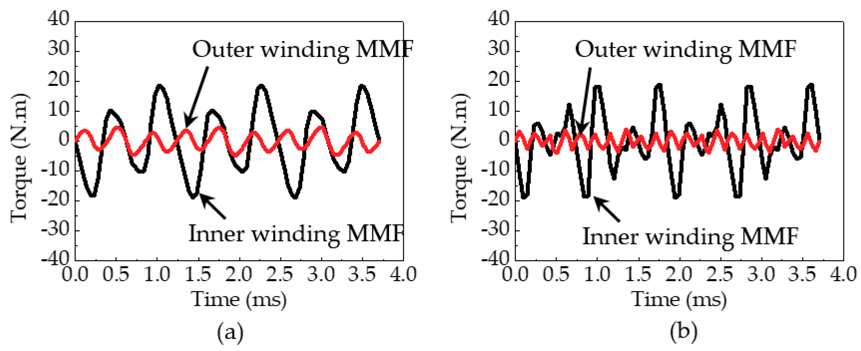
Figure 15 shows the cogging torques by the inner winding MMF and the outer winding MMF when the output rotor is rotated at 1246 rpm and 2492 rpm corresponding to the DC (0 Hz) and AC (270 Hz) operation of the outer winding, respectively. It should be noted that the cogging torque produced by the inner winding MMF is calculated when the outer winding MMF do not exist, and the cogging torque produced by the outer winding MMF is calculated when the inner winding MMF do not exist. The cogging torques produced by the inner winding MMF is much bigger than those produced by the outer winding MMF. This can be expected as the reluctance torque by the inner winding MMF has considerable influence on the ripple of the inner field torque.
7. Conclusions
The novel operating strategy with the extended operating region and divided sub-regions in the doubly fed magnetic geared motor is presented using the individual frequency control in the inner and outer windings. In the case of DFMGM, because two rotating magnetic fields, which are produced by the inner and outer winding MMFs, exist at the air-gap, the space harmonic components by each winding MMF have considerable influence on the performances. The distortions of the no-load back-EMFs occur differently in the inner and outer windings, and its characteristics are varied by the operating conditions. Furthermore, the DFMGM suffers from the disturbance in the torque ripple due to the space harmonic components of the flux density which is produced by the winding MMFs.
In this paper, to clearly see the characteristics of the DFMGM, the performances according to the frequency condition are analyzed in the no-load back-EMF, torque components, and cogging torque. In the inner winding, the fundamental components of the no-load back-EMF have some fluctuation according to the speed variation of the output rotor, and the THD of the no-load back-EMF is much more severe as the output speed is getting higher. On the other hand, the fundamental component of the no-load back-EMF in the outer winding is increased and the THD has decreased, as the output speed is higher. These phenomena are caused by the operating strategy with the individual frequency control in the inner and outer windings; this is most different aspect when compared to the general PM machine.
In addition, the torque characteristics are varied with the frequency condition, and the torque ripples are changed according to how the inner and outer field torques are produced. On the other hand, the fundamental torque has a torque ripple, and the harmonic torques are also largely produced. Hence, in the torque ripple, the effect of the harmonic torque on the resultant output torque is dominant.
Using the cogging torque analysis in the DFMGM, the operating torque is decomposed into the reluctance torque and the magnetic torque, and the effect of the reluctance torque on the operating torque is indirectly predicted. In the case of ripple of the inner field torque, the influence of the reluctance torque by the inner winding MMF is dominant.
Obviously, the space harmonic components of the flux density produced by the winding MMF have considerable influence on the characteristics of the DFMGM. However, unfortunately, the magnetic field modulation causes the space harmonic components of the flux density at the air-gap. To apply the DFMGM in the direct drive systems including EVs, the tasks for the reduction of the space harmonics considering the frequency condition should be conducted. The approach for the space harmonic component of the flux density and the torque contributions on the output torque presented in this paper can help to design the DFMGM, and, in future work, the detailed design including the optimum design will be conducted considering the design requirements, each inverter power in the inner and outer windings, and the division of operating region.
Author Contributions
All authors have contributed to this work. H.S. was the main author of this manuscript and contributed to the theoretical analysis, modeling, simulation, and manuscript preparation. J.C. provided technical guidance for research work and supervised the whole project.
Funding
This research was funded by Basic Science Research Program through the National Research Foundation of Korea (NRF) funded by the Ministry of Education (NRF-2018R1D1A1B07050279 and NRF-2015R1D1A1A01059637).
Conflicts of Interest
The authors declare no conflict of interest.
References
- Rong, F.; Manfeng, D. Optimization design and analysis of a 30kW interior permanent magnet synchronous motor used in electric vehicles. In Proceedings of the 2012 15th International Conference on Electrical Machines and Systems (ICEMS), Sapporo, Japan, 21–24 October 2012. [Google Scholar]
- Jurkovic, S.; Rahman, K.M.; Savagian, P.J. Design, optimization and development of electric machine for traction application in GM battery electric vehicle. In Proceedings of the 2015 IEEE International Electric Machines & Drives Conference (IEMDC), Coeur d’Alene, ID, USA, 10–13 May 2015. [Google Scholar]
- Raminosoa, T.; Torrey, D.A.; El-Refaie, A.; Pan, D.; Grubic, S.; Grace, K. Robust Non-Permanent Magnet Motors for Vehicle Propulsion. In Proceedings of the 2015 IEEE International Electric Machines & Drives Conference (IEMDC), Coeur d’Alene, ID, USA, 10–13 May 2015. [Google Scholar]
- Raminosoa, T.; Torrey, D.; El-Refaie, A.; Grace, K.; Pan, D.; Grubic, S.; Bodla, K.; Huh, K.K. Sinusoidal reluctance machine with DC winding: an attractive non-permanent magnet option. IEEE Trans. Ind. Appl. 2016, 52, 2129–2137. [Google Scholar] [CrossRef]
- Wang, L.L.; Shen, J.X.; Luk, P.C.K.; Fei, W.Z.; Wang, C.F.; Hao, H. Development of a magnetic-geared permanent-magnet brushless motor. IEEE Trans. Magn. 2009, 45, 4578–4581. [Google Scholar] [CrossRef] [Green Version]
- Jian, L.; Gong, W.; Xu, G.; Liang, J.; Zhao, W. Integrated magnetic-geared machine with sandwiched armature stator for low-speed large-torque applications. IEEE Trans. Magn. 2012, 48, 4184–4187. [Google Scholar] [CrossRef]
- Zhang, X.; Liu, X.; Chen, Z. A novel coaxial magnetic gear its integration with permanent-magnet brushless motor. IEEE Trans. Magn. 2016, 52. [Google Scholar] [CrossRef]
- Guo, X.; Wu, S.; Fu, W.; Liu, Y.; Wang, Y.; Zeng, P. Control of a dual-stator flux-modulated motor for electric vehicles. Energies 2016, 9, 517. [Google Scholar] [CrossRef]
- Chen, Y.; Fu, W.; Weng, X. A concept of general flux-modulated electric machines based on a unified theory and its application to developing a novel doubly-fed dual-stator motor. IEEE Trans. Ind. Electron. 2017, 64, 9914–9923. [Google Scholar] [CrossRef]
- Wang, Y.; Ho, S.L.; Fu, W.N.; Shen, J.X. A novel brushless doubly fed generator for wind power generation. IEEE Trans. Magn. 2012, 48, 4172–4175. [Google Scholar] [CrossRef]
- Padmanathan, P.; Bird, J.Z. A continuously variable magnetic gear. In Proceedings of the 2013 International Electric Machines & Drives Conference, Chicago, IL, USA, 12–15 May 2013. [Google Scholar]
- Zheng, P.; Bai, J.; Tong, C.; Sui, Y.; Song, Z.; Zhao, Q. Investigation of a novel radial magnetic-field-modulated brushless double-rotor machine used for HEVs. IEEE Trans. Magn. 2013, 49, 1231–1241. [Google Scholar] [CrossRef]
- Bai, J.; Zheng, P.; Tong, C.; Song, Z.; Zhao, Q. Characteristics analysis and verification of the magnetic-field-modulated brushless double-rotor machine. IEEE Trans. Ind. Electron. 2015, 62, 4023–4033. [Google Scholar] [CrossRef]
- Sun, L.; Cheng, M.; Jia, H. Analysis of a novel magnetic-geared dual-rotor motor with complementary structure. IEEE Trans. Ind. Electron. 2015, 62, 6737–6747. [Google Scholar] [CrossRef]
- Bai, J.; Zheng, P.; Cheng, L.; Zhang, S.; Liu, J.; Liu, Z. A new magnetic-field-modulated brushless double-rotor machine. IEEE Trans. Magn. 2015, 51. [Google Scholar] [CrossRef]
- Liu, Y.; Ho, S.L.; Fu, W.N.; Zhang, X. Design optimization of a novel doubly fed dual-rotor flux-modulated machine for hybrid electric vehicles. IEEE Trans. Magn. 2015, 51. [Google Scholar] [CrossRef]
- Atallah, K.; Calverley, S.D.; Howe, D. Design, analysis and realization of a high-performance magnetic gear. IEE Proc-Electr. Power Appl. 2004, 151, 135–143. [Google Scholar] [CrossRef]
- Spargo, C.M.; Mecrow, B.C.; Widmer, J.D. A seminumerical finite-element postprocessing torque ripple analysis technique for synchronous electric machines utilizing the air-gap maxwell stress tensor. IEEE Trans. Magn. 2014, 50. [Google Scholar] [CrossRef]
Figure 1.
Basic structure: (a) Magnetic geared motor; (b) Doubly Fed Magnetic geared motor (DFMGM).

Figure 2.
Speed-Torque curve of doubly fed magnetic geared motor with the individual frequency control in the windings.
Figure 2.
Speed-Torque curve of doubly fed magnetic geared motor with the individual frequency control in the windings.

Figure 3.
Space harmonic spectra of the modulated flux density produced by the winding MMF: (a) Inner air-gap (by inner winding MMF); (b) Outer air-gap (by inner winding MMF); (c) Inner air-gap (by outer winding MMF); (d) Outer air-gap (by outer winding MMF).
Figure 3.
Space harmonic spectra of the modulated flux density produced by the winding MMF: (a) Inner air-gap (by inner winding MMF); (b) Outer air-gap (by inner winding MMF); (c) Inner air-gap (by outer winding MMF); (d) Outer air-gap (by outer winding MMF).
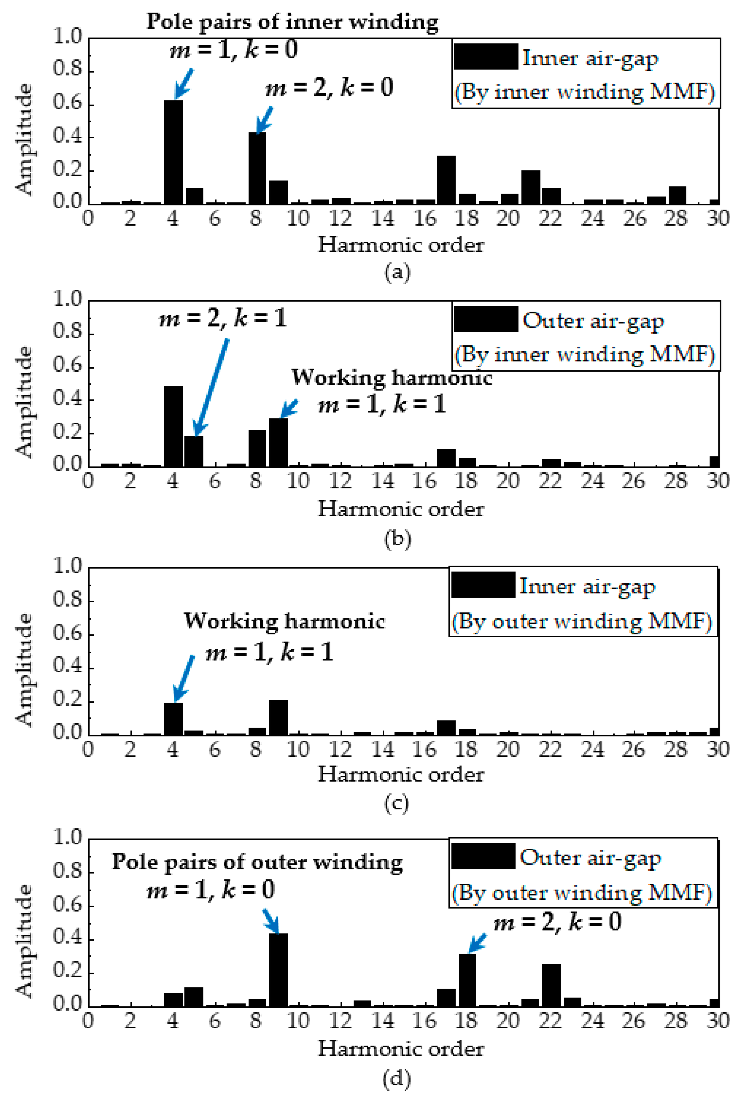
Figure 4.
Pull-out torque curve according to the variation of the winding current: (a) Case of current variation of the inner winding with the rated current (168 Arms) of outer winding; (b) Case of current variation of the outer winding with the rated current (424 Arms) of inner winding.
Figure 4.
Pull-out torque curve according to the variation of the winding current: (a) Case of current variation of the inner winding with the rated current (168 Arms) of outer winding; (b) Case of current variation of the outer winding with the rated current (424 Arms) of inner winding.
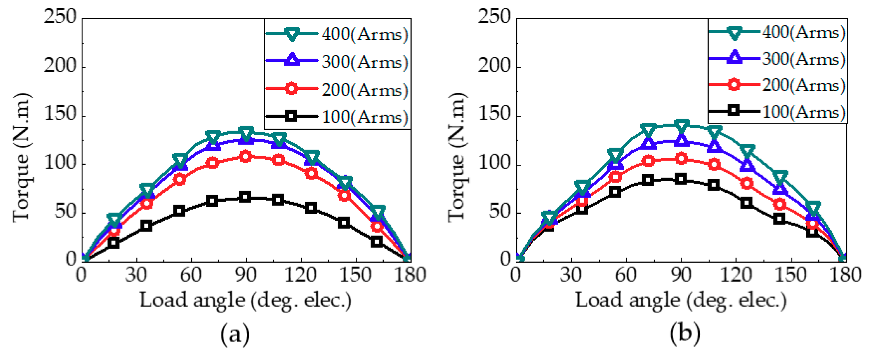
Figure 5.
Operating characteristics of DFMGM: (a) Performance according to the variation of the frequency of the outer winding; (b) Instantaneous torque with time when the outer winding operates at 0 Hz (DC operation); (c) Instantaneous torque with time when the outer winding operates at 90 Hz.
Figure 5.
Operating characteristics of DFMGM: (a) Performance according to the variation of the frequency of the outer winding; (b) Instantaneous torque with time when the outer winding operates at 0 Hz (DC operation); (c) Instantaneous torque with time when the outer winding operates at 90 Hz.
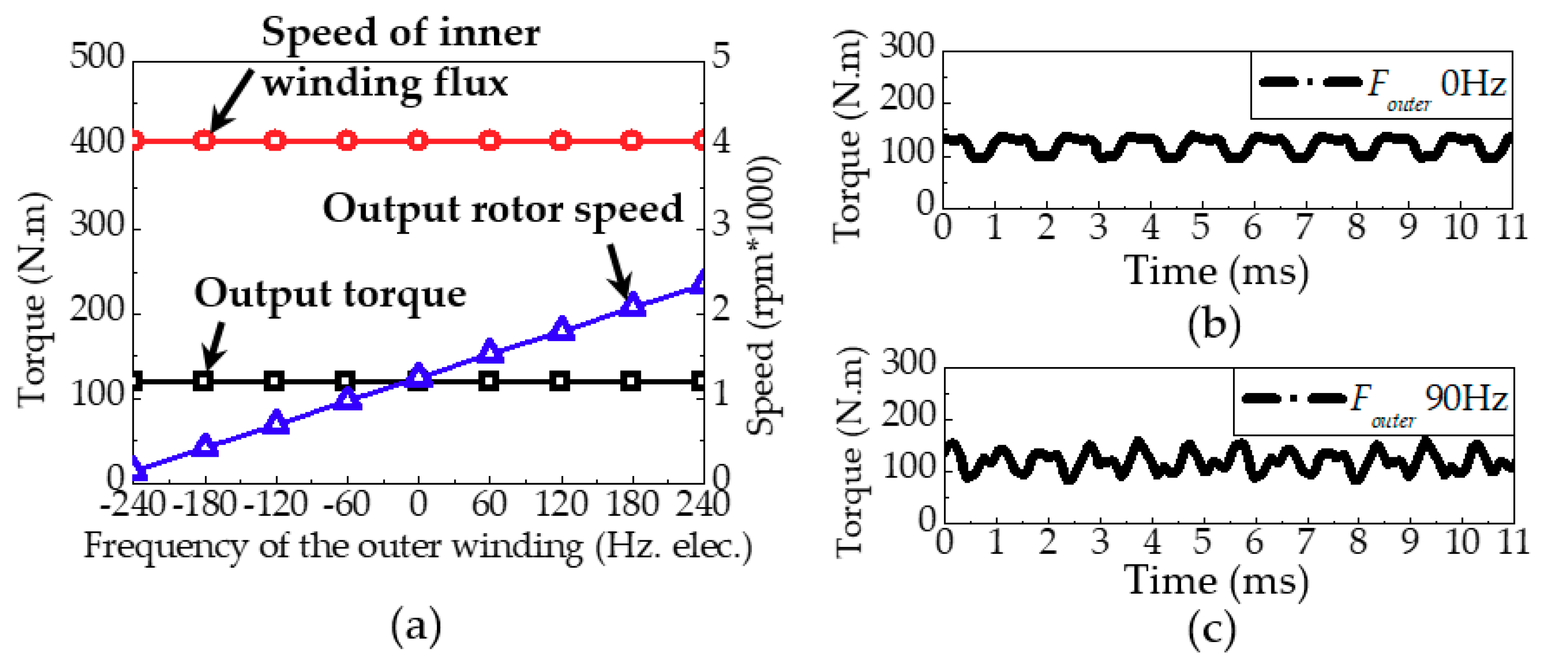
Figure 6.
Characteristics of no-load back-EMF of 270 Hz in the inner winding: (a) Waveforms when the output rotor and the outer winding operate at 1246 rpm and 0 Hz, respectively; (b) Time harmonic spectra of Figure 6a; (c) Waveforms when the output rotor and the outer winding operate at 1662 rpm and 90 Hz, respectively; (d) Time harmonic spectra of Figure 6c.
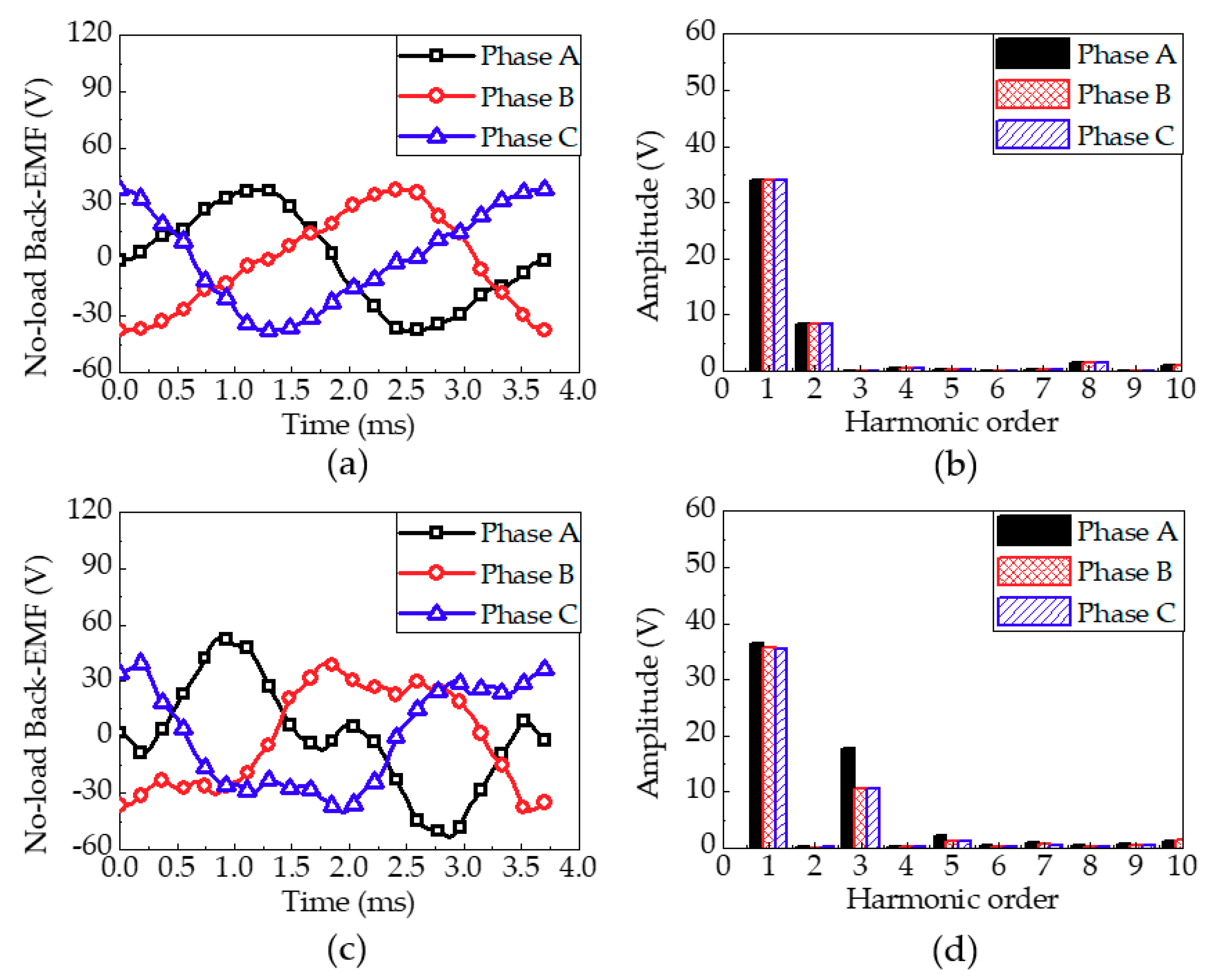
Figure 7.
Characteristics of no-load back-EMF with 0 Hz in the outer winding when the output rotor and the inner winding operate at 124 rpm and 270 Hz, respectively: (a) Waveforms of phase A; (b) Waveforms of phase B; (c) Waveforms of phase C; (d) Time harmonic spectra.
Figure 7.
Characteristics of no-load back-EMF with 0 Hz in the outer winding when the output rotor and the inner winding operate at 124 rpm and 270 Hz, respectively: (a) Waveforms of phase A; (b) Waveforms of phase B; (c) Waveforms of phase C; (d) Time harmonic spectra.

Figure 8.
Characteristics of no-load back-EMF with 90 Hz in the outer winding when the output rotor and the inner winding operate at 1662 rpm and 270 Hz, respectively: (a) Waveforms of phase A; (b) Waveforms of phase B; (c) Waveforms of phase C; (d) Time harmonic spectra.
Figure 8.
Characteristics of no-load back-EMF with 90 Hz in the outer winding when the output rotor and the inner winding operate at 1662 rpm and 270 Hz, respectively: (a) Waveforms of phase A; (b) Waveforms of phase B; (c) Waveforms of phase C; (d) Time harmonic spectra.
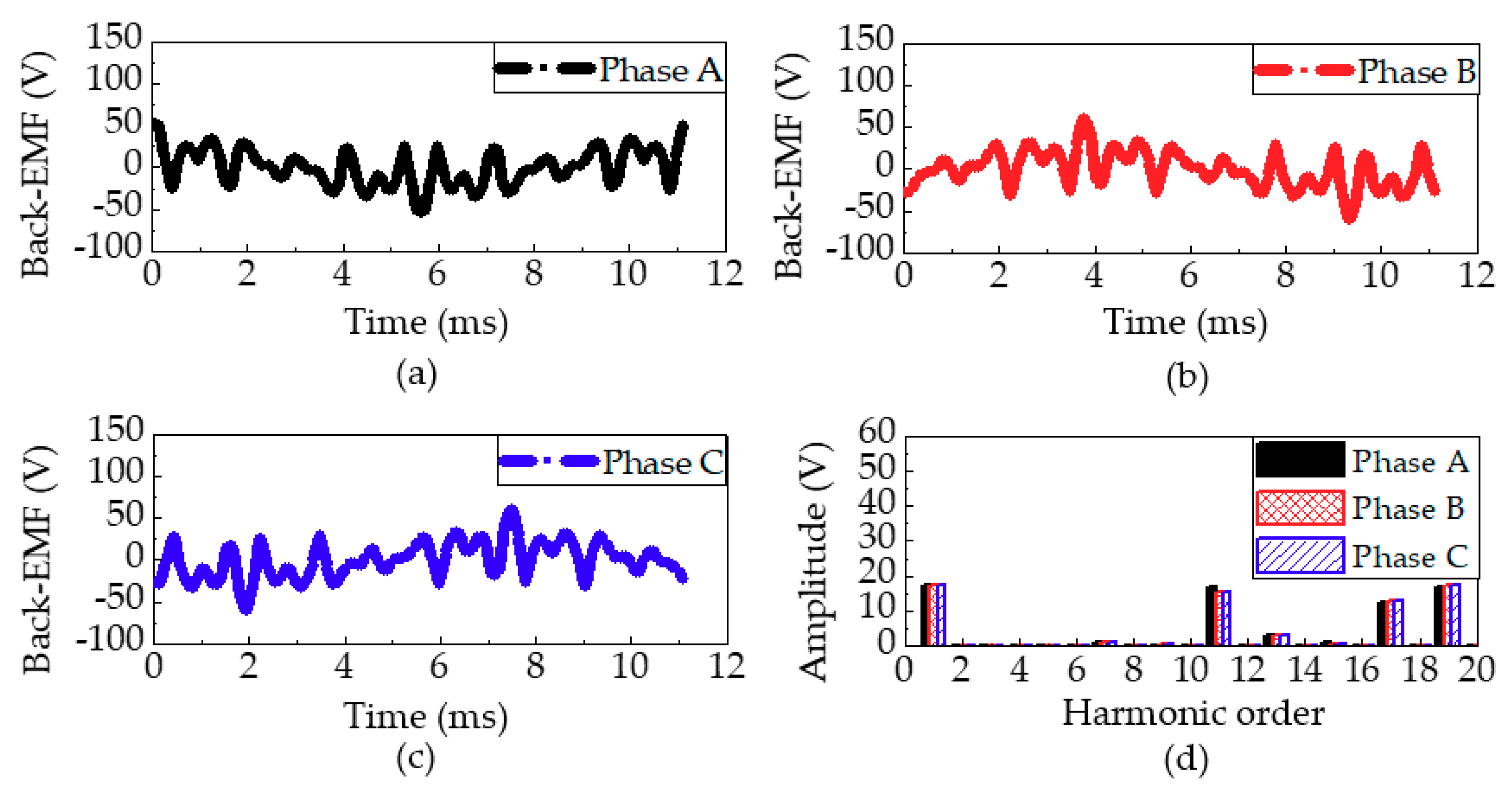
Figure 9.
Speed-Torque curve with the base speed I of 1246 rpm and the base speed II of 2492 rpm, respectively.
Figure 9.
Speed-Torque curve with the base speed I of 1246 rpm and the base speed II of 2492 rpm, respectively.
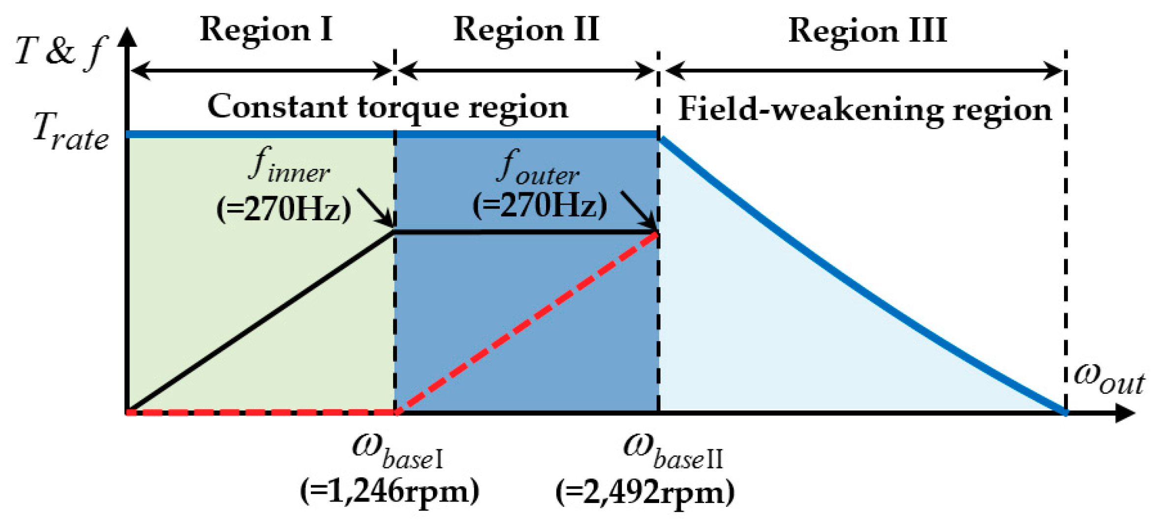
Figure 10.
No-load back-EMF characteristics with the variation of the speed of the output rotor in the inner and outer windings: (a) Fundamental component and THD in the inner winding; (b) Fundamental component and THD in the outer winding.
Figure 10.
No-load back-EMF characteristics with the variation of the speed of the output rotor in the inner and outer windings: (a) Fundamental component and THD in the inner winding; (b) Fundamental component and THD in the outer winding.
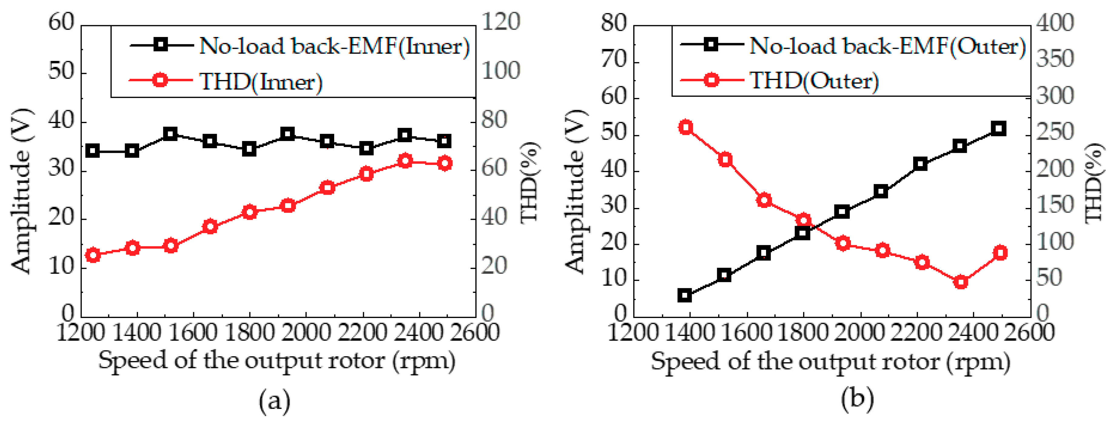
Figure 11.
Torque characteristics with the variation of the speed of the output rotor in region II.
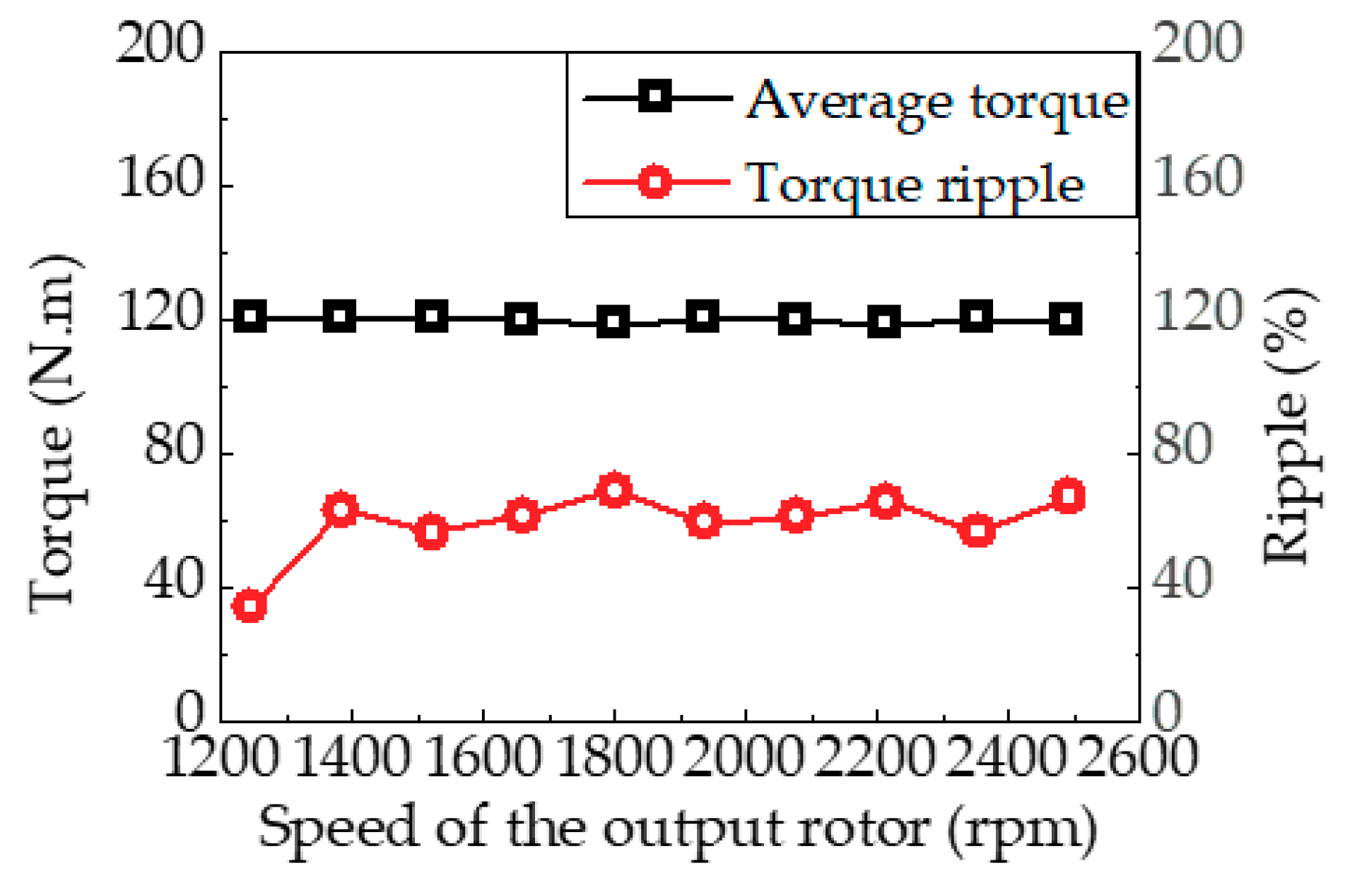
Figure 12.
Torque contribution for the output rotor torque in the inner field and the outer field: (a) When the output rotor operates at 1246 rpm (finner = 270 Hz, fouter = 0 Hz); (b) When the output rotor operates at 2492 rpm (finner = 270 Hz, fouter = 270 Hz).
Figure 12.
Torque contribution for the output rotor torque in the inner field and the outer field: (a) When the output rotor operates at 1246 rpm (finner = 270 Hz, fouter = 0 Hz); (b) When the output rotor operates at 2492 rpm (finner = 270 Hz, fouter = 270 Hz).
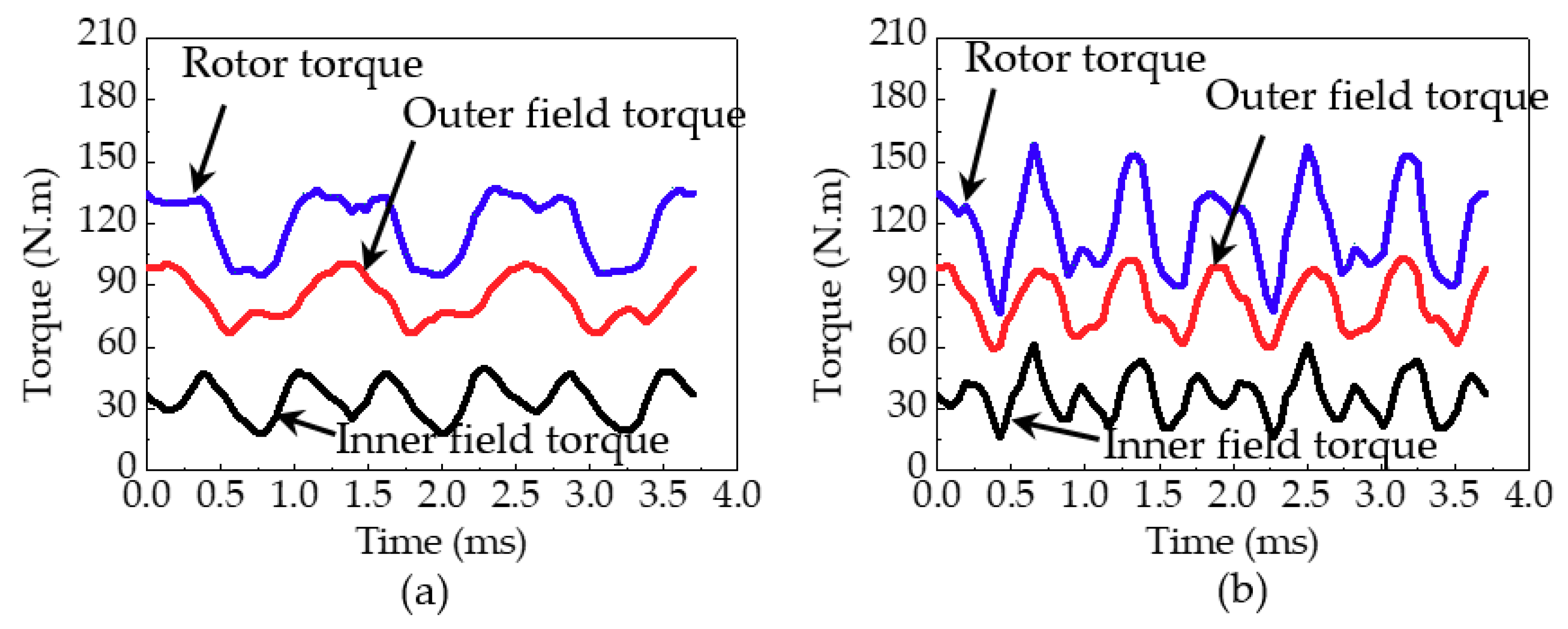
Figure 13.
Torque contribution of the fundamental component torque and the harmonic torque when the output rotor operated at 1246 rpm (finner = 270 Hz, fouter = 0 Hz): (a) Inner field torque; (b) Outer field torque.
Figure 13.
Torque contribution of the fundamental component torque and the harmonic torque when the output rotor operated at 1246 rpm (finner = 270 Hz, fouter = 0 Hz): (a) Inner field torque; (b) Outer field torque.
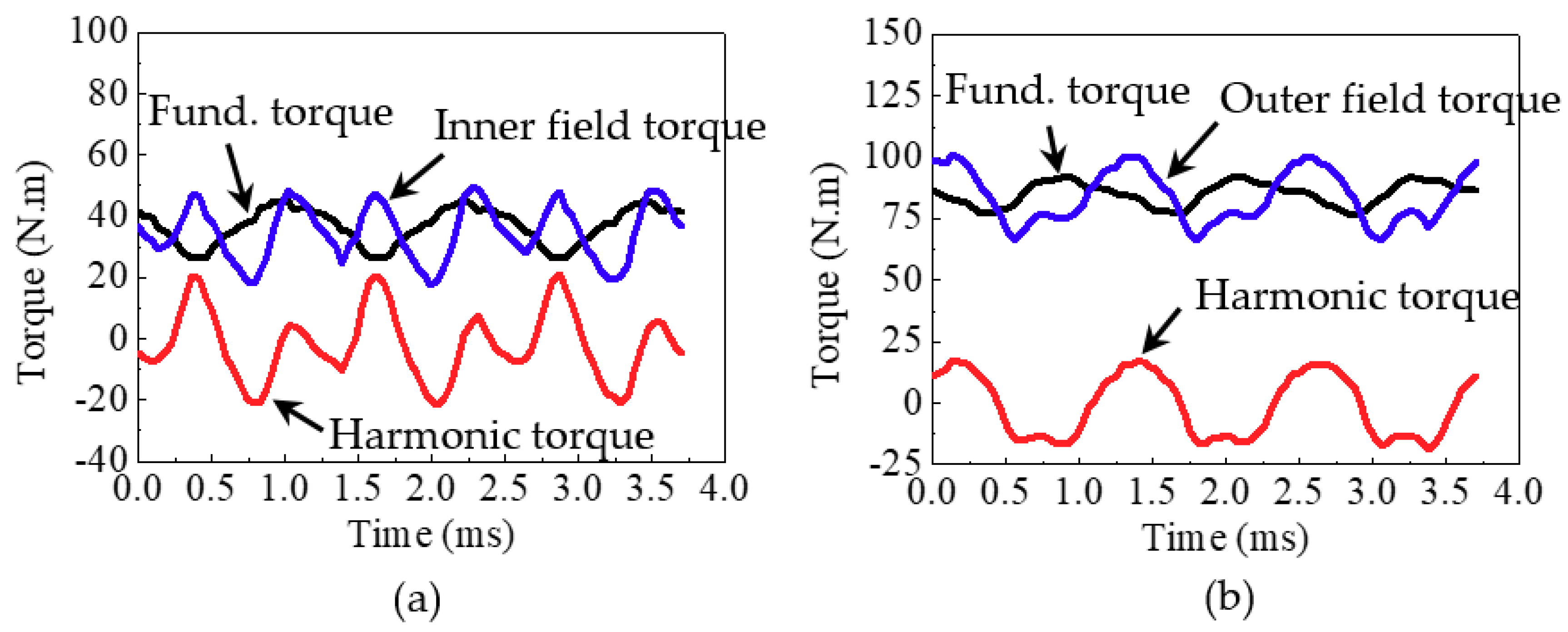
Figure 14.
Torque contribution of the fundamental component torque and the harmonic torque when the output rotor operated at 2492 rpm (finner = 270 Hz, fouter = 270 Hz): (a) Inner field torque; (b) Outer field torque.
Figure 14.
Torque contribution of the fundamental component torque and the harmonic torque when the output rotor operated at 2492 rpm (finner = 270 Hz, fouter = 270 Hz): (a) Inner field torque; (b) Outer field torque.

Figure 15.
Cogging torque characteristics: (a) Cogging torques produced by the inner winding MMF (finner = 270 Hz) and the outer winding MMF (fouter = 0 Hz), respectively, when the output rotor operated at 1246 rpm; (b) Cogging torques produced by the inner winding MMF (finner = 270 Hz) and the outer winding MMF (fouter = 270 Hz), respectively, when the output rotor operated at 2492 rpm.

Table 1.
Specifications of the analysis model.
| Contents | Value |
|---|---|
| Diameter (mm) | 269 |
| Stack length (mm) | 156 |
| Number of pole pair of inner winding | 4 |
| Number of pole pair of outer winding | 9 |
| Number of modulating pieces | 13 |
| Base speed (rpm) | 2492 |
| Current density of wire (Arms/mm2) | 10 |
| Fill factor | 0.55 |
| Phase Current (inner/outer), (Arms) | 424/168 |
| Number of turns per phase (inner/outer) | 16/36 |
Table 2.
Specifications of the winding configurations.
| Contents | Inner Winding | Outer Winding |
|---|---|---|
| Type | Concentrated | |
| Layer | Double | |
| Number of slots | 12 | 27 |
| Number of slots per phase per pole, Spp | 1/2 | 1/2 |
| Number of coils | 4 | 9 |
| Number of turns per coil | 4 | 4 |
| Number of turns per phase | 16 | 36 |
| Wire | AWG1 | AWG5 |
© 2018 by the authors. Licensee MDPI, Basel, Switzerland. This article is an open access article distributed under the terms and conditions of the Creative Commons Attribution (CC BY) license (http://creativecommons.org/licenses/by/4.0/).
Share and Cite
MDPI and ACS Style
Shin, H.; Chang, J. Characteristics Analysis of Doubly Fed Magnetic Geared Motor Considering Winding Frequency Conditions. Energies 2018, 11, 2564. https://doi.org/10.3390/en11102564
AMA Style
Shin H, Chang J. Characteristics Analysis of Doubly Fed Magnetic Geared Motor Considering Winding Frequency Conditions. Energies. 2018; 11(10):2564. https://doi.org/10.3390/en11102564
Chicago/Turabian StyleShin, Homin, and Junghwan Chang. 2018. "Characteristics Analysis of Doubly Fed Magnetic Geared Motor Considering Winding Frequency Conditions" Energies 11, no. 10: 2564. https://doi.org/10.3390/en11102564
Note that from the first issue of 2016, this journal uses article numbers instead of page numbers. See further details here.