1. Introduction
With the absence of mechanical gearboxes, permanent magnet (PM) direct-drive machines have attracted more and more attention in recent years with the rapid increase of low-speed large-torque (LSLT) applications, such as wind power generation, robotics, ship propulsion, electrical vehicles, wave energy conversion, and railway traction [
1,
2,
3]. In PM direct-drive machines, field-modulated permanent magnet (FMPM) machines are promising candidates for these LSLT applications because FMPM machines working based on the so-called “magnetic gearing effect” possess the inherent merits of high torque density and high efficiency [
4]. Integrated magnetic-geared machines (IMGMs) and PM vernier machines are the most common ones in FMPM machines. However, since there exist multi-layer air-gaps [
5,
6,
7,
8,
9,
10,
11], IMGMs suffer from complex mechanical structures, thus resulting in a decrease in practicality. On the contrary, PM vernier machines with simple structures are favored and widely investigated by researchers [
12,
13,
14,
15,
16,
17,
18,
19,
20]. Only one set of PMs is employed in all of the aforementioned PM vernier machines, and the PMs are either on the stator or on the rotor. Namely, one kind of machine is rotor type (RT) [
12,
13,
14], and the other belongs to stator type (ST) [
17,
18,
19,
20,
21,
22,
23]. The torque capability of these PM vernier machines is limited, as the precious spaces in stator and rotor for the assembly of PMs are not made full use of.
In order to break through the limitation of the torque capability, novel PM machines with two sets of PMs on both the stator and rotor were proposed in [
2,
21,
22,
23,
24]. This kind of machine was first named “dual-permanent-magnet-excited (DPME) machine” in 2013 [
25], where “bi-directional field modulation effect (BFME)” was first proposed to elaborate the operating principle. According to the “BFME”, it is easy to know the pole-pair number (PPN) relationship between the two sets of PMs and armature windings, and how to design this kind of machine. References [
25,
26] have confirmed that DPME machines can offer lager torque than both ST and RT PM vernier machines; performance between DPME machines with fewer stator poles and fewer rotor poles were compared in [
27], which has point out that the DPME machines with fewer rotor poles have better torque capability; surface response methodology was used to optimize the design of a DPME machine in [
28]; DPME machines with Halbach PM arrays were proposed and analyzed on behalf of further improving the torque in [
26,
29,
30,
31]. In terms of all the aforementioned DPME machines with PM arrays or without PM arrays, they have something in common in the structure, that is, all of the PMs are located in the slots formed by the iron teeth, and consequent poles are applied to these machines in order to artfully realize the BFME. Obviously, there is a fact that the usage of PMs increases when adopting BFME to design DPME machines. And rare-earth PMs are used in most aforementioned DPME machines. As reported in [
32,
33,
34,
35,
36], with the rapid increase of the demand of rare-earth PMs, there is a worldwide concern, because nearly 96% of rare-earth elements’ production is provided by China, the cost of rare-earth PM is so high and the supply is easily restricted by exporting countries. Therefore, in addition to the pursuit of the torque density when designing DPME machines, the intensity of PM utilization (kg/kW) also needs to be considered. However, the intensity of PM utilization of most DPME machines from the cited literatures is not taken into account.
A novel DPME machine will be proposed in this paper. Two sets of PMs are also employed in the stator and rotor, and its rotor also adopts the consequent poles. What is the significant difference from all the DPME machines in the cited references is that not all PMs are in the slots. Specifically, the stator PMs magnetized along radial direction are located under the short stator iron teeth, while the stator PMs magnetized tangentially are located in the slots formed by the long stator iron teeth and the stator PMs magnetized along radial direction. Each long stator iron tooth is clamped by two tangentially magnetized PMs with opposite directions. Thus, the flux strengthening effect will occur in this machine and the air-gap flux density will be improved. The performance of the proposed machine, including torque density, intensity of PM utilization, power factor, losses, efficiency, etc., will be analyzed and compared with a DPME machine from a literature by using finite element method (FEM). The organization of this paper is as follows. In
Section 2, the configuration of the proposed machine will be introduced in detail. In
Section 3, the working principle will be revealed. In
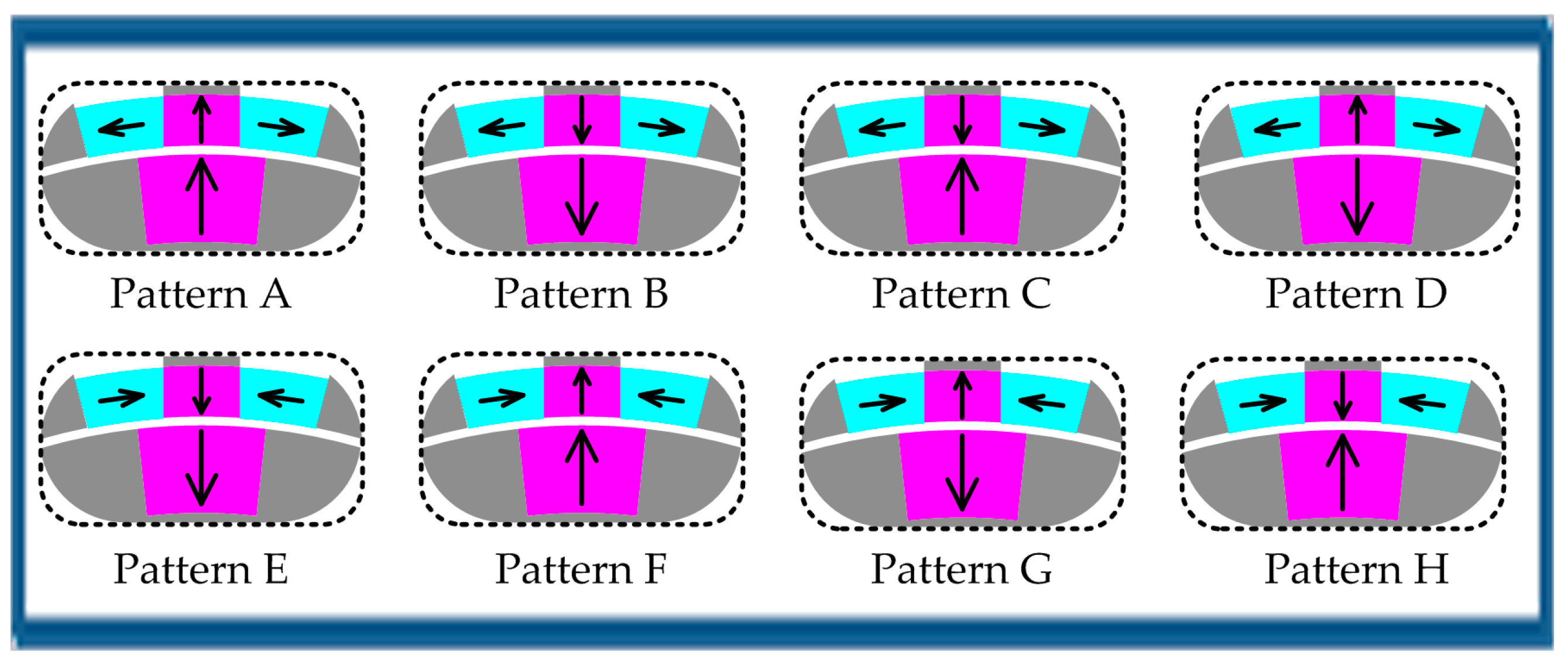
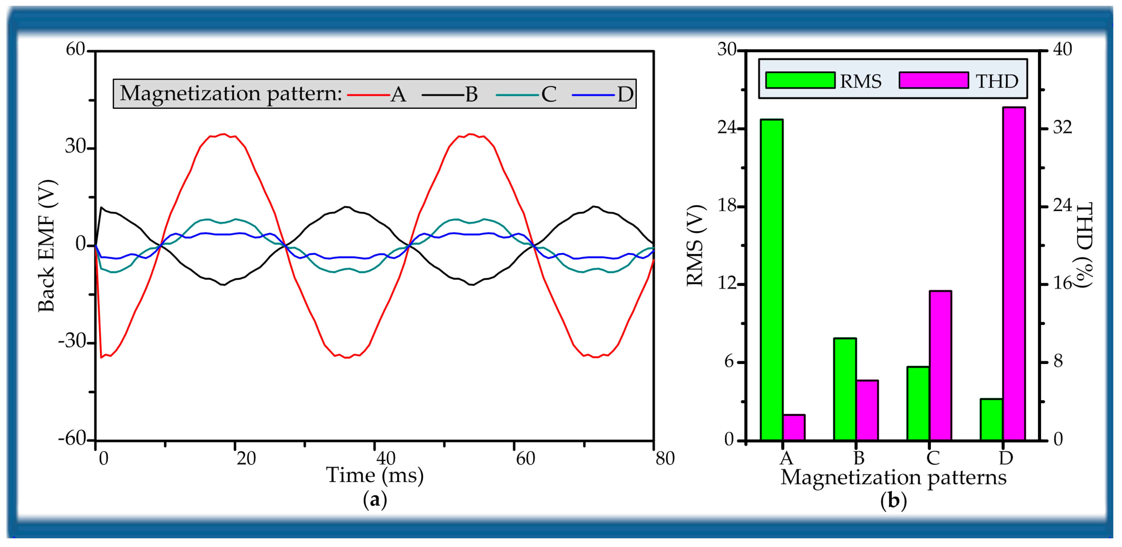
Section 4, different PM magnetization patterns will be studied, and electromagnetic performance of the proposed machine with optimal magnetization pattern will be analyzed by the FEM simulation. In
Section 5, comparative study between the proposed machine and a DPME machines from a literature will be performed in order to confirm the flux strengthening effect and compare their performance. Finally, the conclusions will be drawn in
Section 6.
2. Machine Configuration
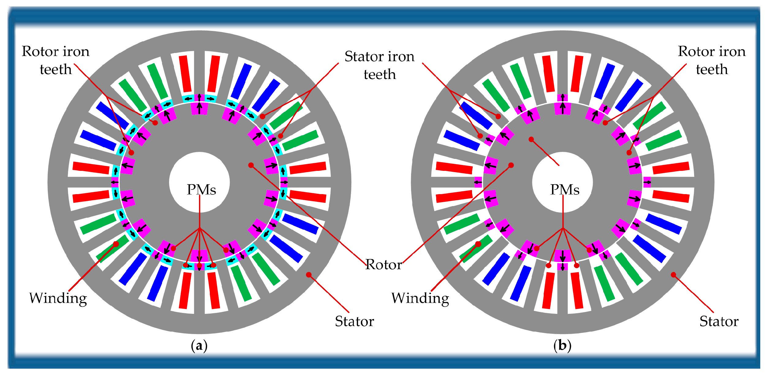
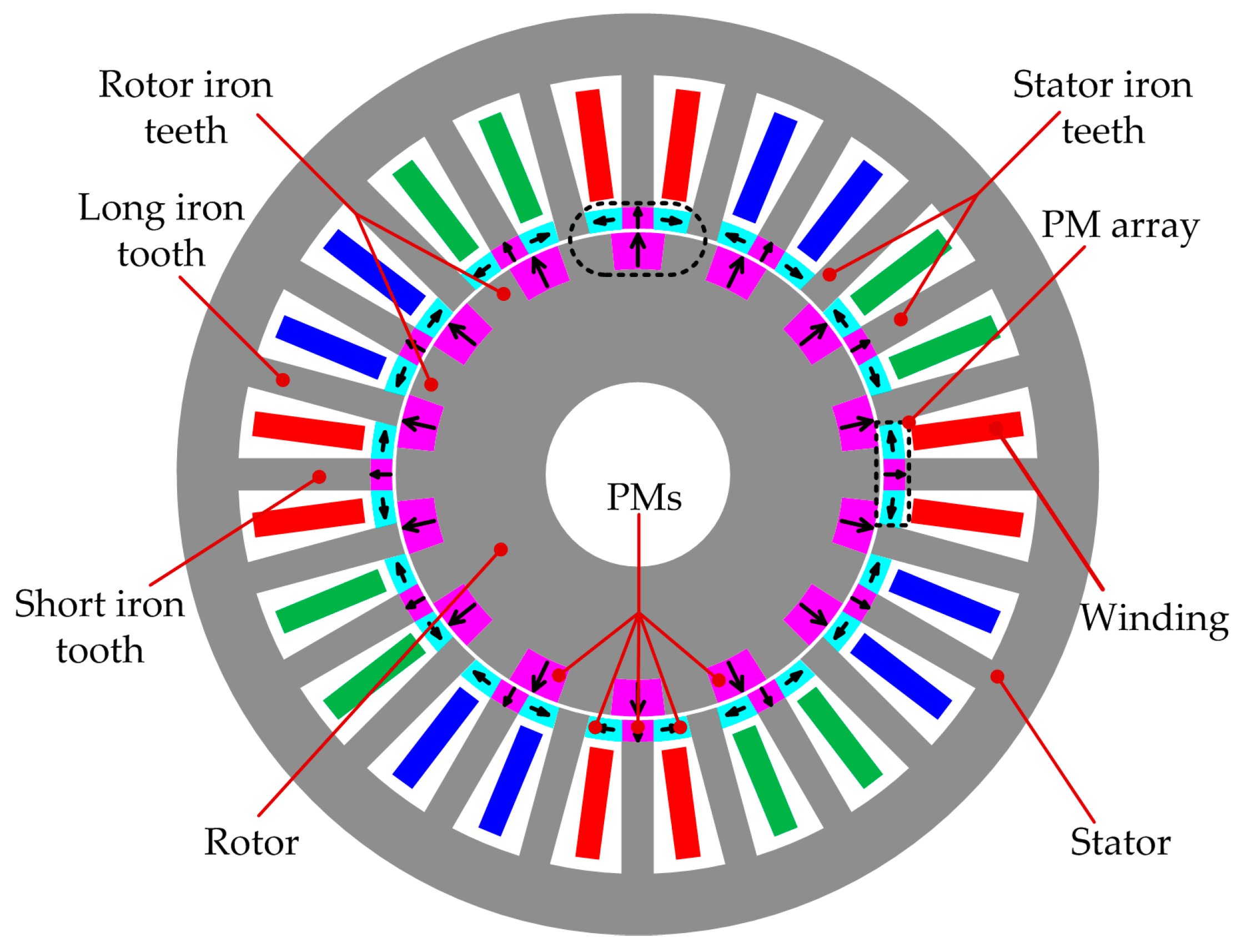
Figure 1 shows the basic configuration of the proposed DPME machine. It consists of a rotor and a stator. The rotor PMs are inserted into the rotor core. All of the rotor PMs are magnetized along either radial outward direction or radial inward direction. The stator is composed of a slotted stator core wound with three-phase armature windings and several duplicate PM arrays. It is worth noting that the stator core has a number of stator iron teeth with unequal lengths, and the long and short stator iron teeth are arranged alternately along the circumference. For each PM array, it is constituted of three PMs and their magnetization directions differ from each other. Wherein, the stator PM under the short stator iron tooth is magnetized along either radial outward direction or radial inward direction, while the other two PMs are tangentially magnetized with opposite directions.
In the proposed machine, each rotor PM and its adjacent rotor iron tooth form a pair of magnet poles. Thus, the PPN of the rotor PMs denoted by p1 is the same as the number of the rotor iron teeth. Similar to the rotor PMs, each stator PM magnetized along the radial direction and its adjacent long stator iron tooth form a pair of magnet poles. But, unlike the rotor PMs, the stator PM magnetized along the radial direction is separated from a long stator iron teeth by a tangentially magnetized PM. Therefore, the PPN of the stator PMs denoted by p2 is equal to the number of the long rotor iron teeth, and half the number of the stator iron teeth or stator slots. In addition every two tangentially magnetized PMs with opposite directions clamp a long stator iron tooth, which can cause the flux strengthening effect and improve the air-gap flux density.
The main features of the proposed machine are summarized as follows:
The proposed machine employs two sets of PMs, one with PM arrays on the stator and the other on the rotor. Based on BFME, it can achieve the effective coupling between the magnetic field excited by the armature windings and those excited by the two sets of PMs. As a result, the machine can offer much higher torque capability.
Both the stator and rotor magnetic poles adopt the consequent poles. Especially for the stator magnetic pole, a pair of magnet poles is formed by a PM under a short iron tooth and its adjacent long iron tooth. What is different from the rotor magnetic poles is that the PM under the short iron tooth is separated from a long iron teeth by a PM magnetized tangentially.
The arrangement of a long stator iron tooth and two tangentially magnetized PMs with opposite directions is capable of strengthening the PM fluxes, hence improving the flux density.
For the stator teeth, there are PMs under the short stator iron teeth. Since the relative permeability of PMs is close to that of the air, the field modulating effect of the short stator iron teeth is weakened, and the long stator iron teeth mainly serves as the field modulating teeth. Thus, the number of stator iron teeth serving as field modulating teeth can be considered to be half the number of the stator iron teeth. For the rotor, the rotor iron teeth play the role of field modulating teeth.
It is interesting that the number of the rotor and stator iron teeth with field modulating effect is equal to the PPN of the rotor PMs and stator PMs, respectively.
3. Working Principle
The working principle of the proposed DPME machine is based on the so-called BFME. Similar to the function of ferromagnetic pieces in magnetic gears, the long stator iron teeth and the rotor iron teeth serving as field modulating teeth play the role of modulating magnetic fields that are excited by different magnetic sources. So, the magnetic fields excited by the rotor PMs, stator PMs, and armature windings can be modulated into abundant field harmonics in the air-gap. Harmonics with exactly the same PPN and rotational speed will couple together to produce stable electromagnetic torque. To reveal the working principle of the proposed machine clearly, the field harmonics excited by rotor PMs, stator PMs, and armature windings are investigated in detail.
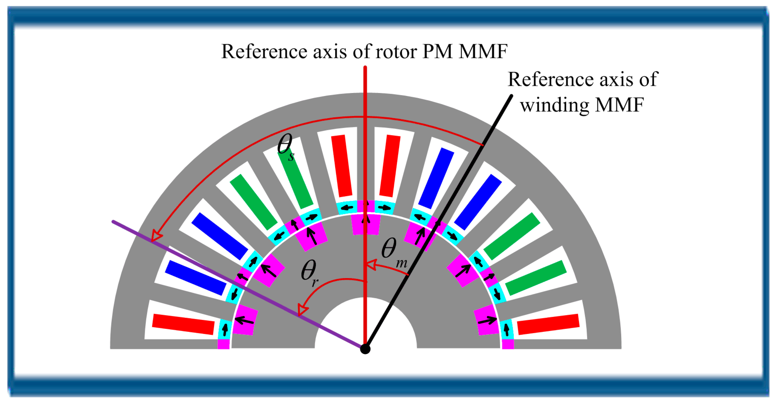
Firstly, the air-gap flux density due to rotor PMs is investigated. The magnetomotive force (MMF) of rotor PMs can be expressed by its Fourier series:
where
is the amplitude of the fundamental component of the rotor PM MMF;
,
, and
are the mechanical angles of the winding MMF, the rotor PM MMF and the rotor position, respectively, the details of which are shown in
Figure 2;
, and
the speed of the rotor.
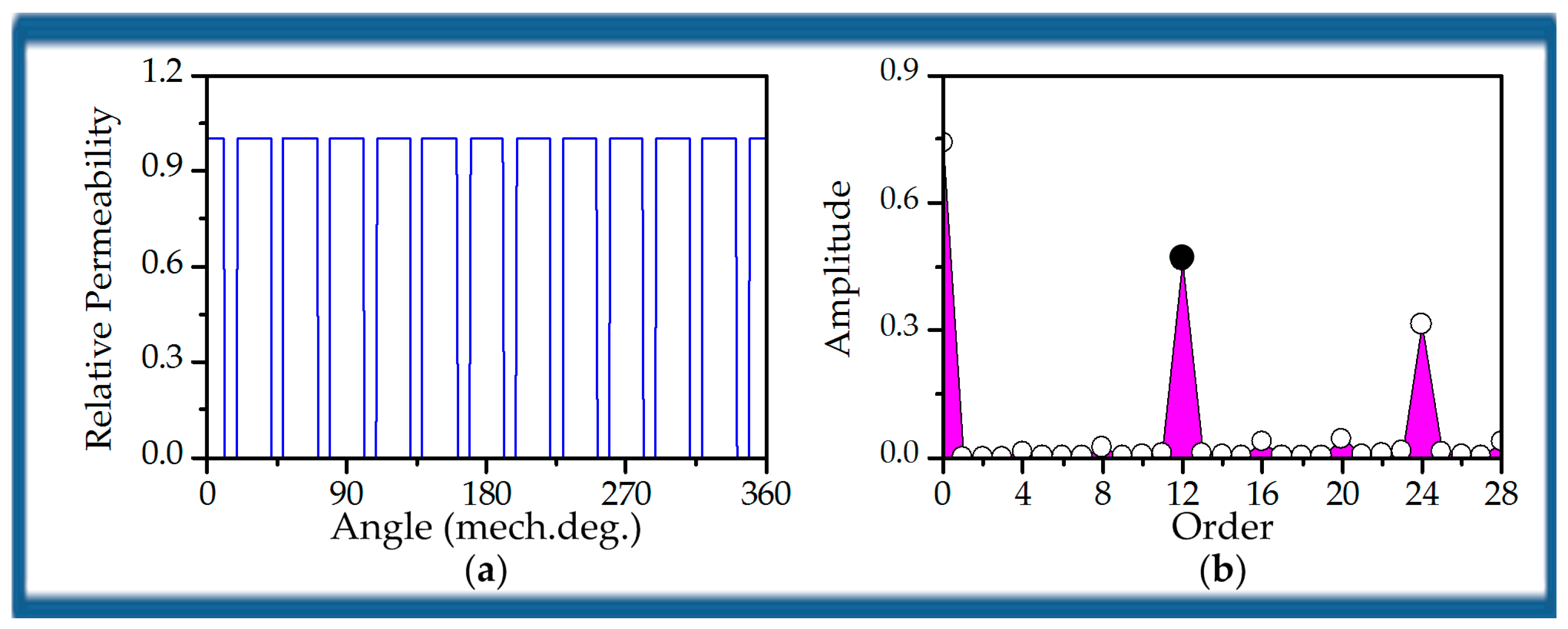
Since the number of the long stator iron teeth serving as field modulating teeth is equal to the PPN of the stator PMs, the air-gap permeance function due to the long stator teeth can be expressed by its Fourier series:
where
, and
are the constant component and the amplitude of the
kth harmonic in (2), respectively.
The air-gap flux density produced by the rotor PMs,
, can be obtained by calculating the product of
and
,
From (3), we can see that the flux density produced by the rotor PMs contains three groups. One is the original harmonics with PPN =
, and these harmonics rotate with the same speed of rotor. The other two groups are harmonics with PPN =
and PPN =
, and the corresponding speeds are
and
, respectively. These two harmonic groups are generated due to the field modulating effect of the long stator iron teeth. The detailed harmonic PPNs and corresponding speeds are listed in
Table 1.
Secondly, the air-gap flux density due to stator PMs is studied. Similarly, the MMF of stator PMs can be expressed by its Fourier series:
where
is the amplitude of the fundamental component of the stator MMF.
Since the number of the rotor iron teeth serving as field modulating teeth is equal to the PPN of the rotor PMs, the air-gap permeance function due to the rotor iron teeth can be expressed by its Fourier series:
where
, and
are the constant component and the amplitude of the
kth harmonic in (5), respectively.
The air-gap flux density excited by the stator PMs,
, can be obtained by multiplying
and
.
From (6), we can see that the flux density produced by the stator PMs can be divided into three groups. The static harmonics with PPN =
are the original harmonics of stator PMs. The rotating harmonics with PPN =
and PPN =
, and the corresponding speeds are
and
, respectively. The negative notation means that these harmonics rotate opposite to the rotor direction. These two rotating harmonic groups are generated due to the field modulating effect of the rotor iron teeth. The detailed harmonic PPNs and corresponding speeds are listed in
Table 2.
Finally, the magnetic field excited by armature windings is analyzed. The MMF produced by three-phase sinusoidal alternating current (AC) is given by
where
is the winding factor of the
mth harmonic;
is the PPN of the armature windings;
is the angular frequency of the currents;
is the total turns of the single phase winding; and,
is the effective value of the currents.
The magnetic field excited by armature windings can be modulated simultaneously by the long stator iron teeth and rotor teeth. By calculating the product of
,
and
, the flux density excited by the armature currents can be obtained as follows:
where
,
,
, and
are coefficients in (8). It is necessary to explain that they are not given in (8) in order to reduce the length of the formula, and both
k1 and
k2 are positive integers.
From (8), we can see that the flux density excited by armature windings can be categorized into four groups. The first group is the original harmonics that are neither modulated by the stator teeth nor modulated by the rotor teeth, the second and the third groups are the armature fields modulated by the stator teeth and the rotor teeth, respectively, the last group is harmonics modulated by both the stator teeth and the rotor teeth. The detailed harmonic PPNs and corresponding speeds are listed in
Table 3.
In order to output stable electromagnetic torque, the two interacted field harmonics should have the same PPN and the same rotating speed. Only the highest harmonic components are taken into consideration when
m =
k = h = 1. It can be found that if
there exist effective field harmonics with exactly the same PPN and rotational speed, as shown in
Table 4. It should be noted that the same color in
Table 4 represents effective field harmonics with exactly the same PPN and rotational speed.
5. Comparative Study
As shown in
Figure 15, two DPME machines are selected for comparative study. One is the proposed DPME machine with magnetization pattern A, and the other one is from [
38]. It can be found from
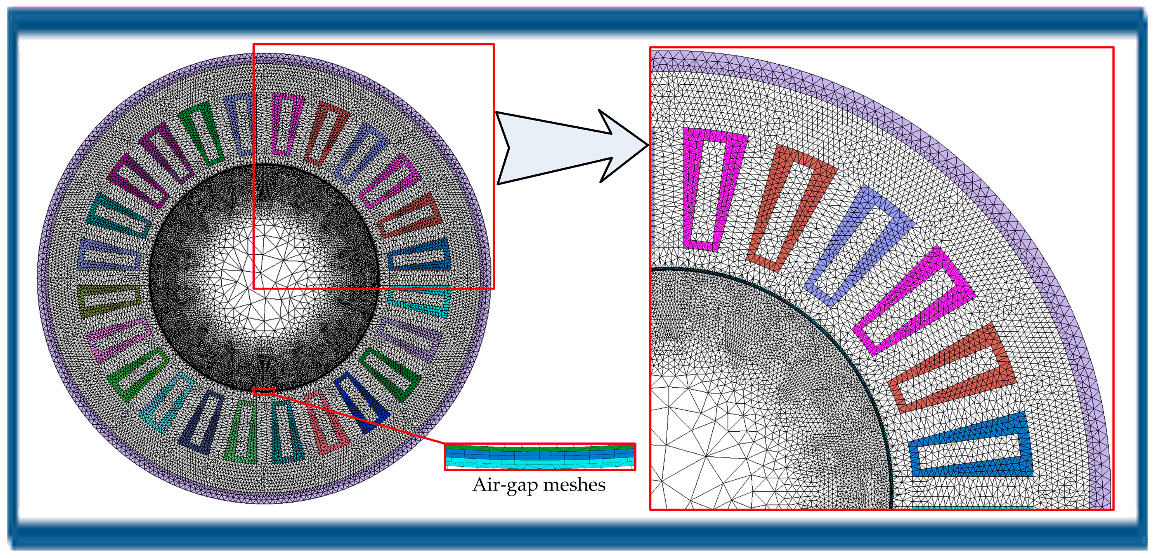
Figure 15 that Machine I can be obtained by removing the tangentially magnetized PMs, and it is fortunate that we can easily ensure that the two machines have the same the size, the same winding connection, the same electric load, and the same PPN combination of stator PMs and rotor PMs for fair comparison. The simulation models of Machine I are built based on the parameters in
Table 5. The simulation models of them have the same mesh.
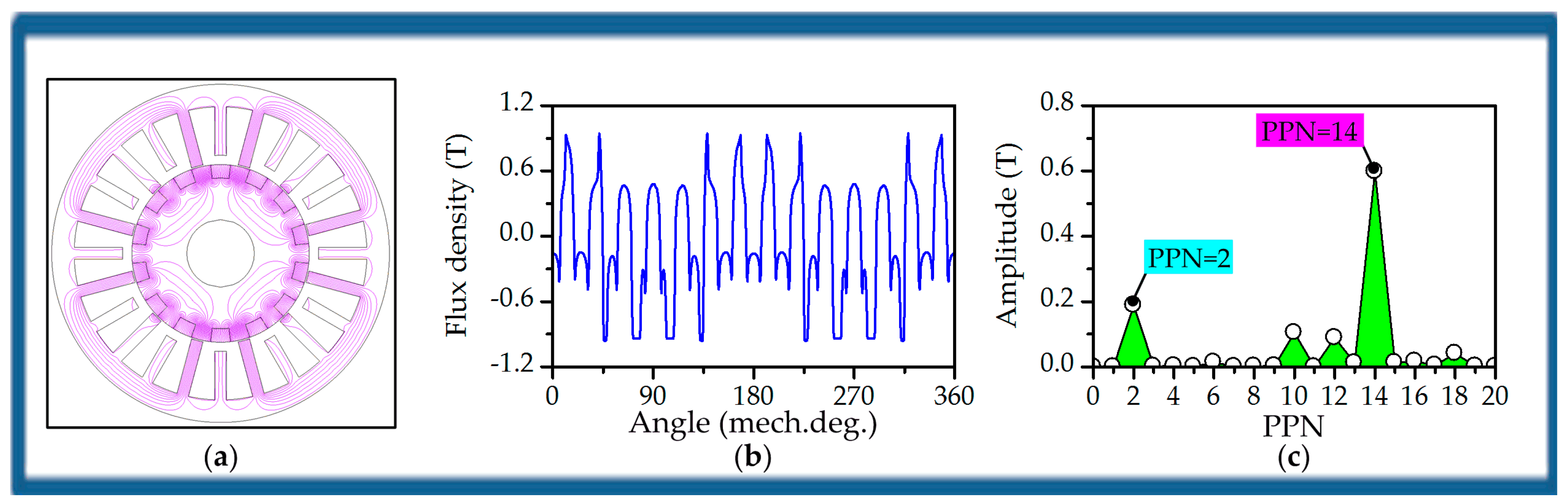
Since Machine I has the same stator core, armature windings, rotor core and rotor PMs as the proposed machine, the magnetic fields excited only by rotor PMs and armature windings are the same as the proposed machine in
Figure 7 and
Figure 9.
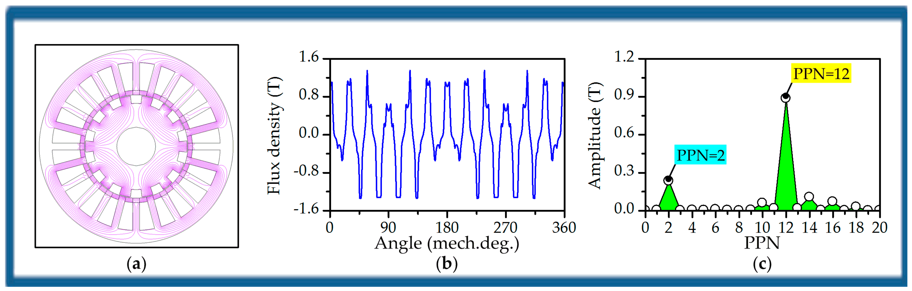
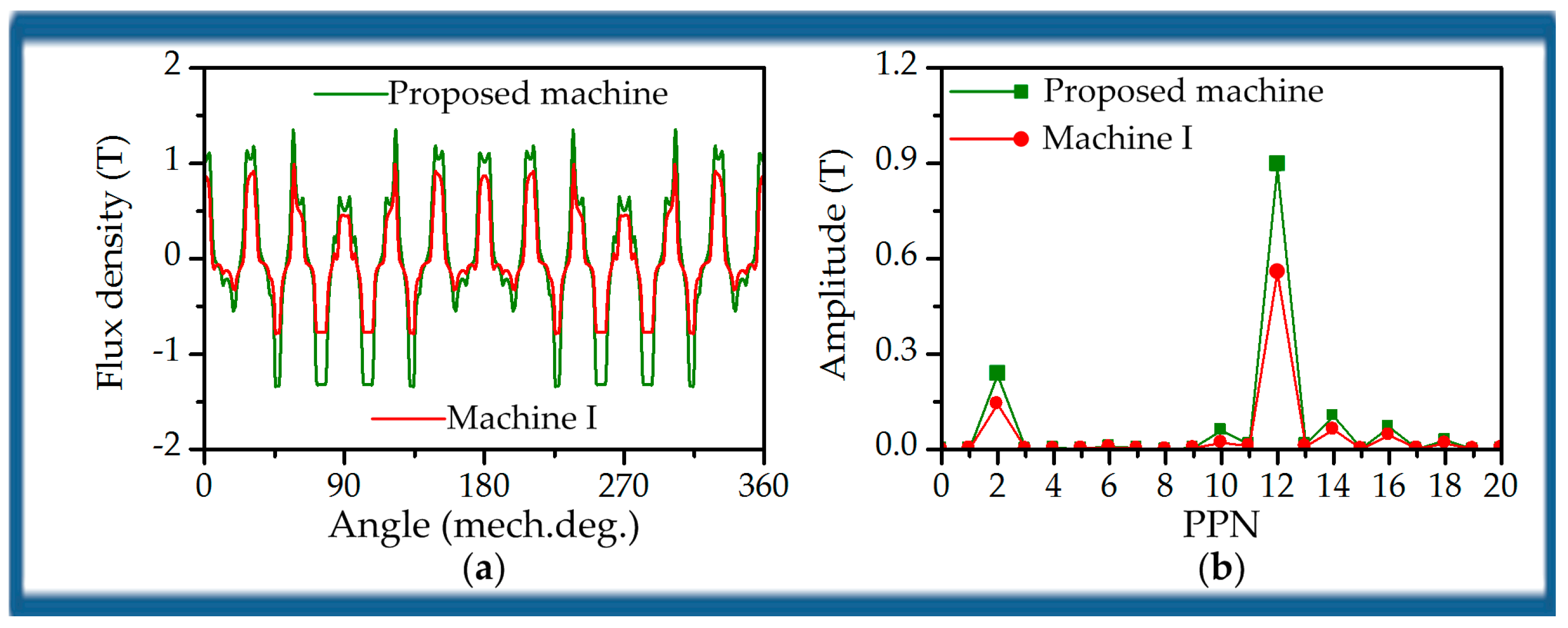
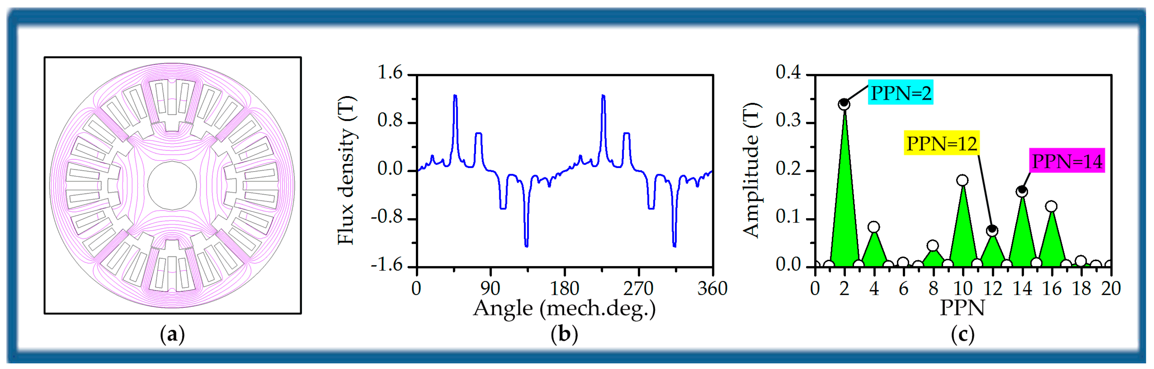
Figure 16 compares the magnetic fields excited only by stator PMs between the two machines. It can be seen that the magnetic field of the proposed machine is stronger than Machine I due to flux strengthening effect arising from the arrangement of a long stator iron tooth and two tangentially magnetized PMs.
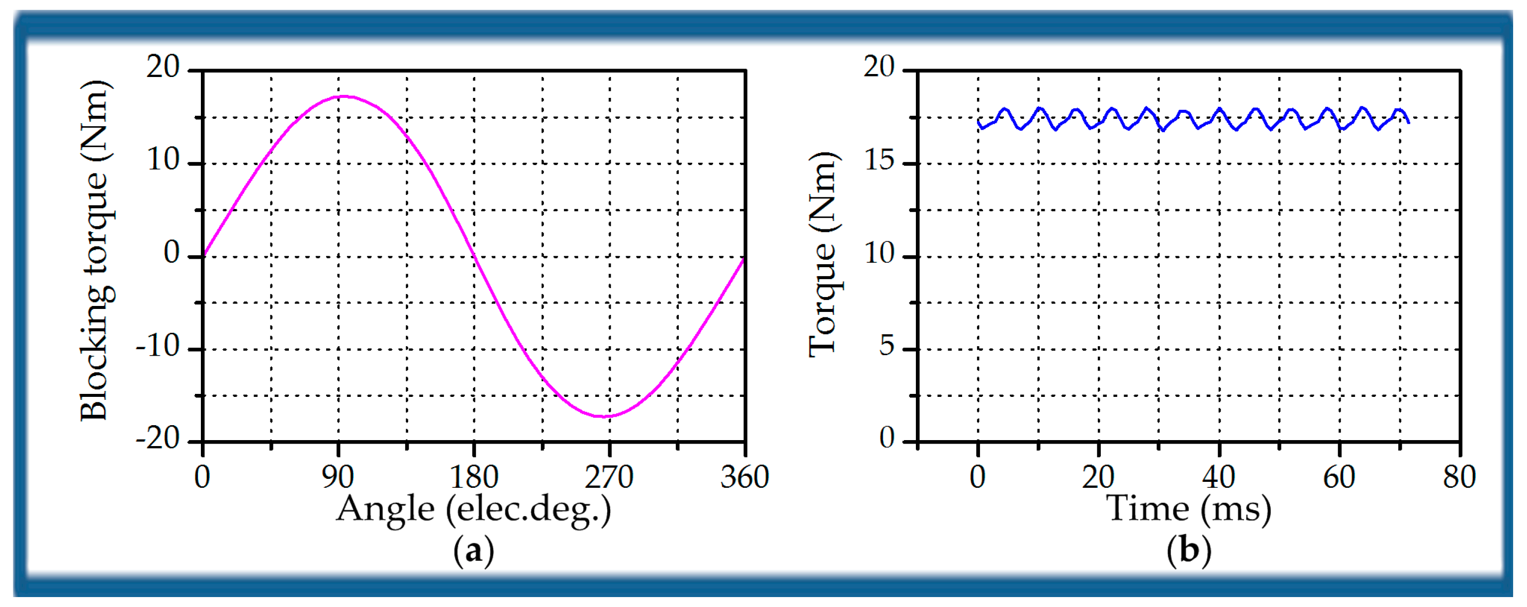
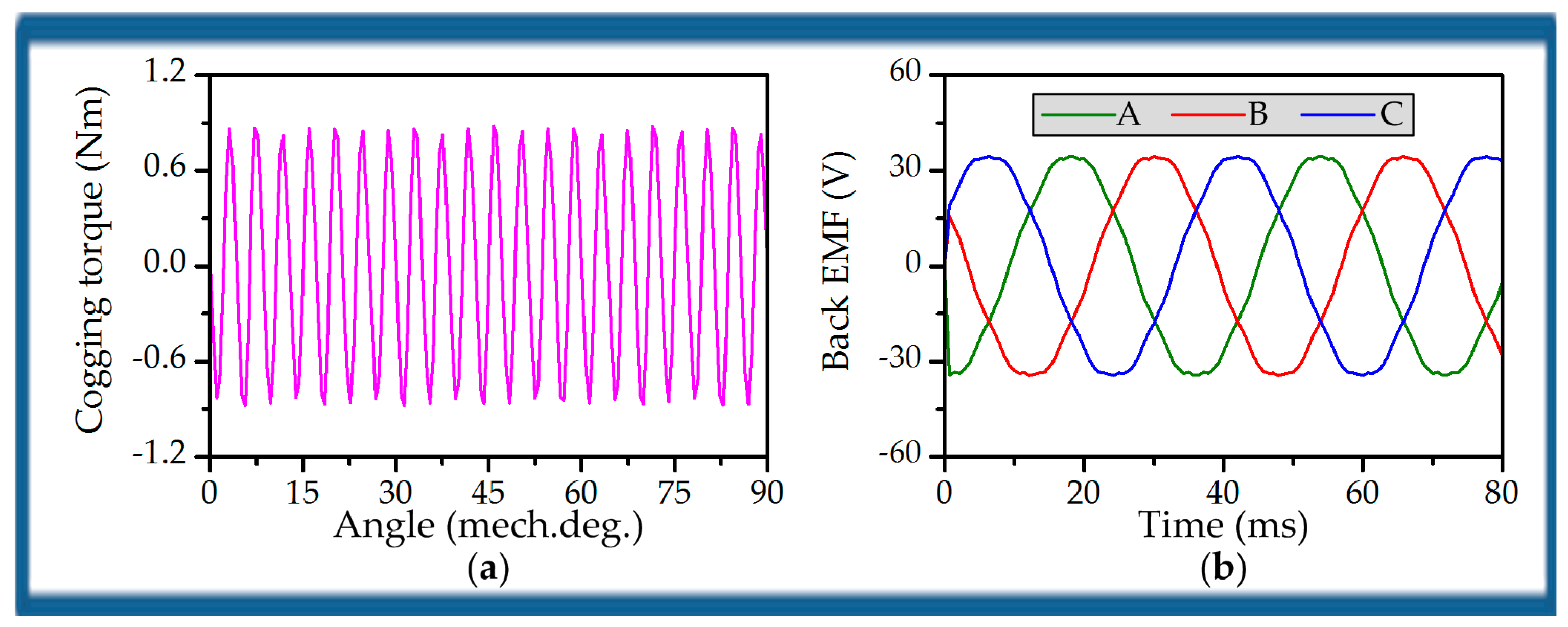
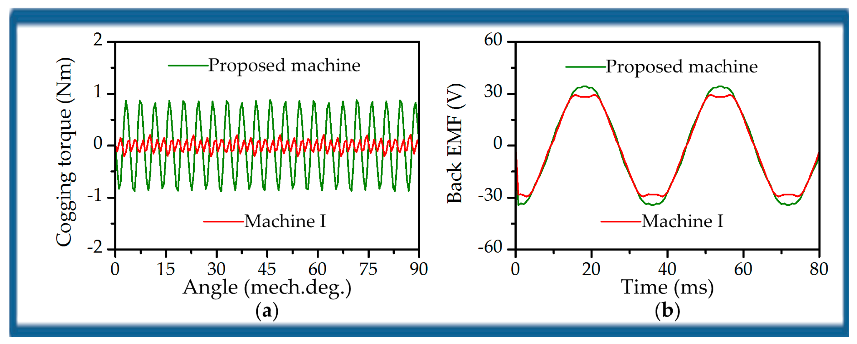
Figure 17a compares their cogging torques when the rotor turns 90 degrees and the maximum value of the proposed machine and Machine I is 0.88 Nm and 0.21 Nm, respectively. Apparently, the proposed machine has much larger cogging torque than Machine I.
Figure 17b compares phase back EMFs with the two machines at the speed of 120 r/min. As can be seen, both the machines have the same electric cycle, and the amplitude of the proposed machine is larger than that of Machine I. Moreover, THD of the back EMF can be obtained by post processing and THD of the proposed machine and Machine I is 2.63% and 7.69%, respectively. Hence, it can be concluded that the proposed machine can offer larger back EMF with smaller THD in comparison with Machine I.
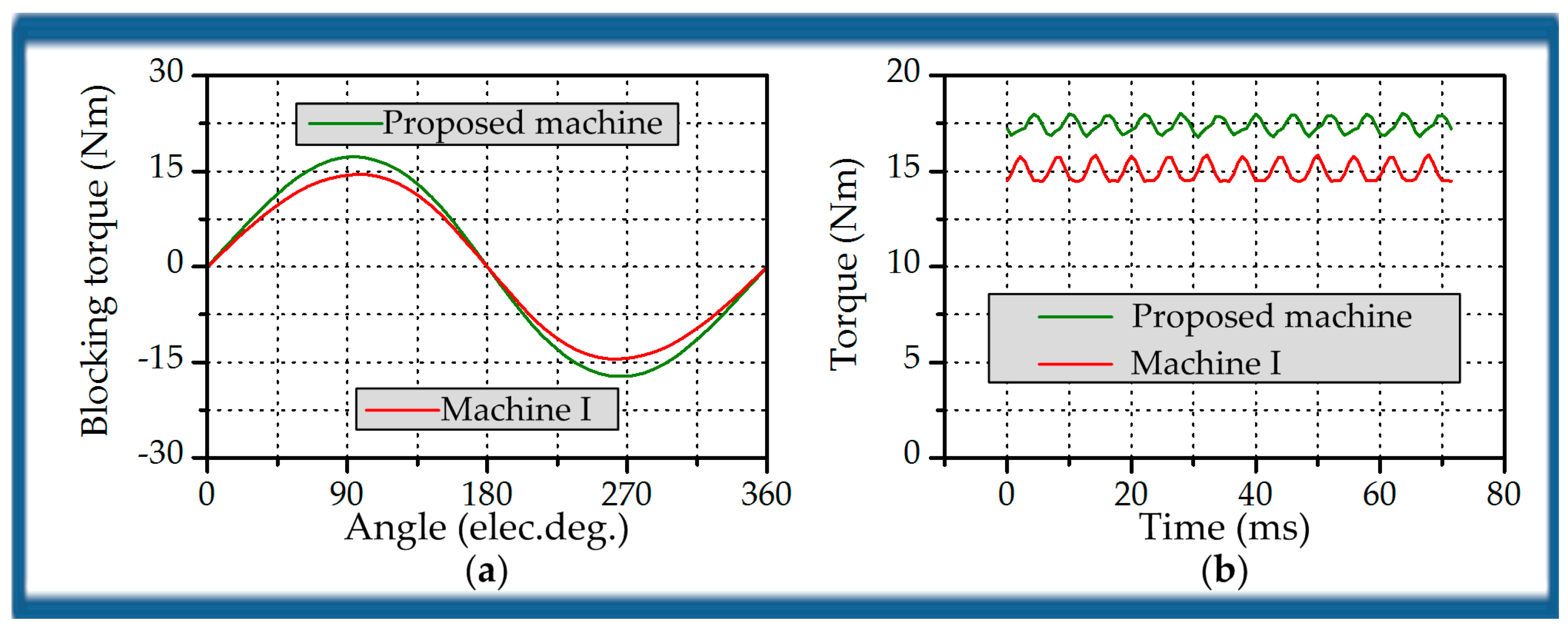
Figure 18a compares the torque capability of the two machines with the same current. It is evident that the proposed machine can offer larger torque than Machine I due to the BFME and flux strengthening effect.
Figure 18b gives the stable torque-time curves when three-phase currents with
I = 3 A are injected into the two machines and both of them rotate at 120 r/min. It can be known that the average torque that is offered by the proposed machine and Machine I is 17.39 Nm and 14.99 Nm, respectively. Moreover, the torque ripple ratios of the two machines are listed in
Table 6. It can be observed that the proposed machine can offer larger torque with smaller torque ripple.
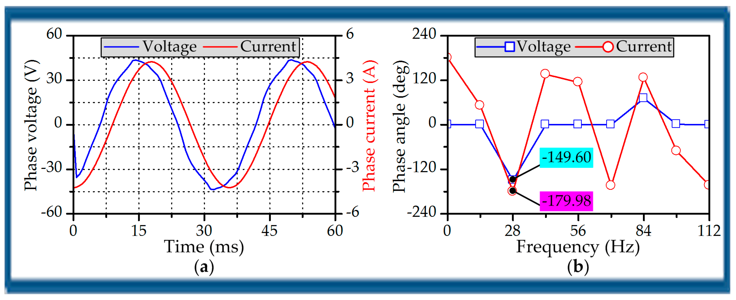
Table 6 also lists the PF angle and PF when three-phase currents with
I = 3 A are injected into the two machines and both of them rotate at 120 r/min. Apparently, the PF of the proposed machine is also larger than Machine I. But, when compared with the conventional PM synchronous machine (PMSM), the PFs of them are really poor.
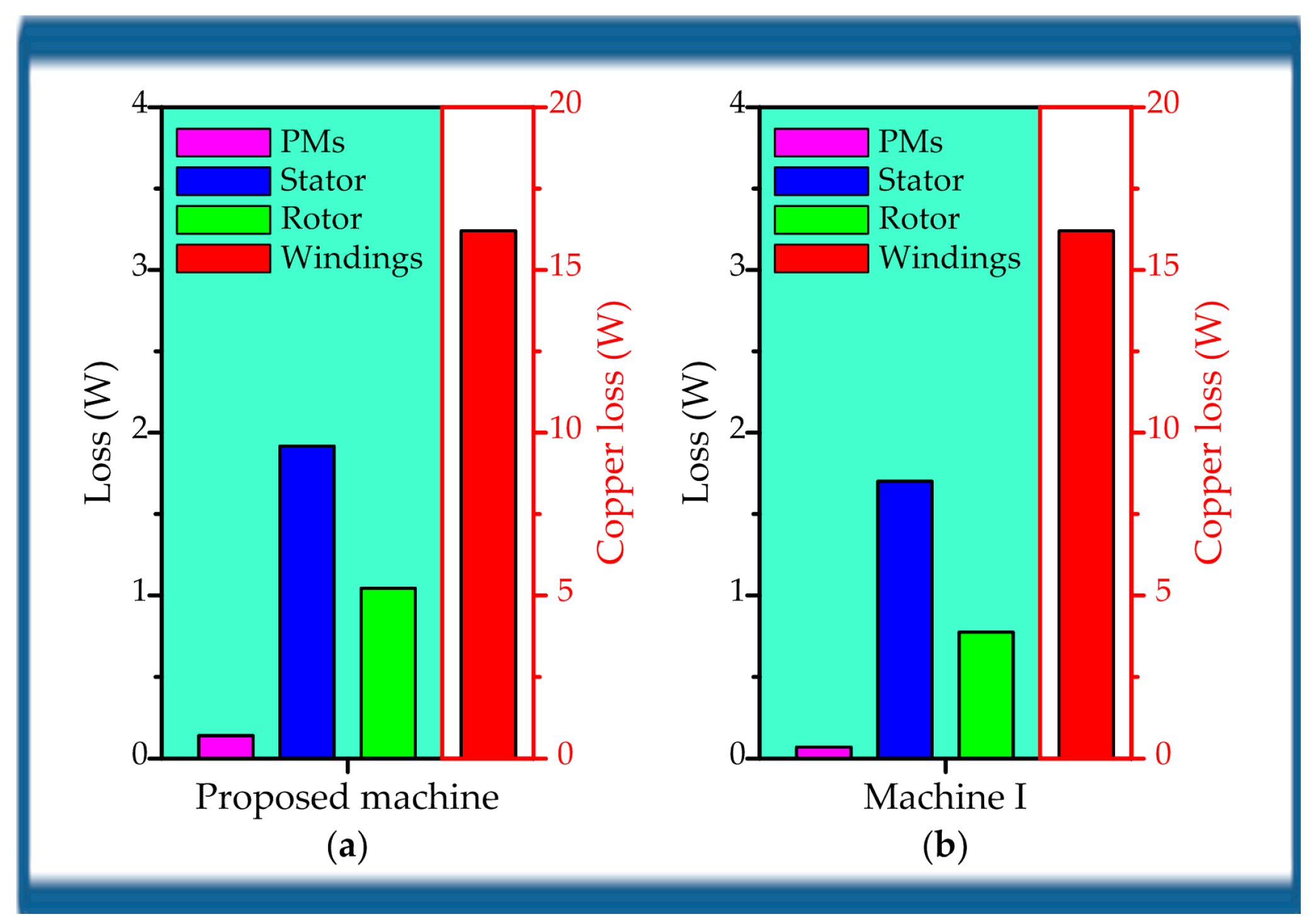
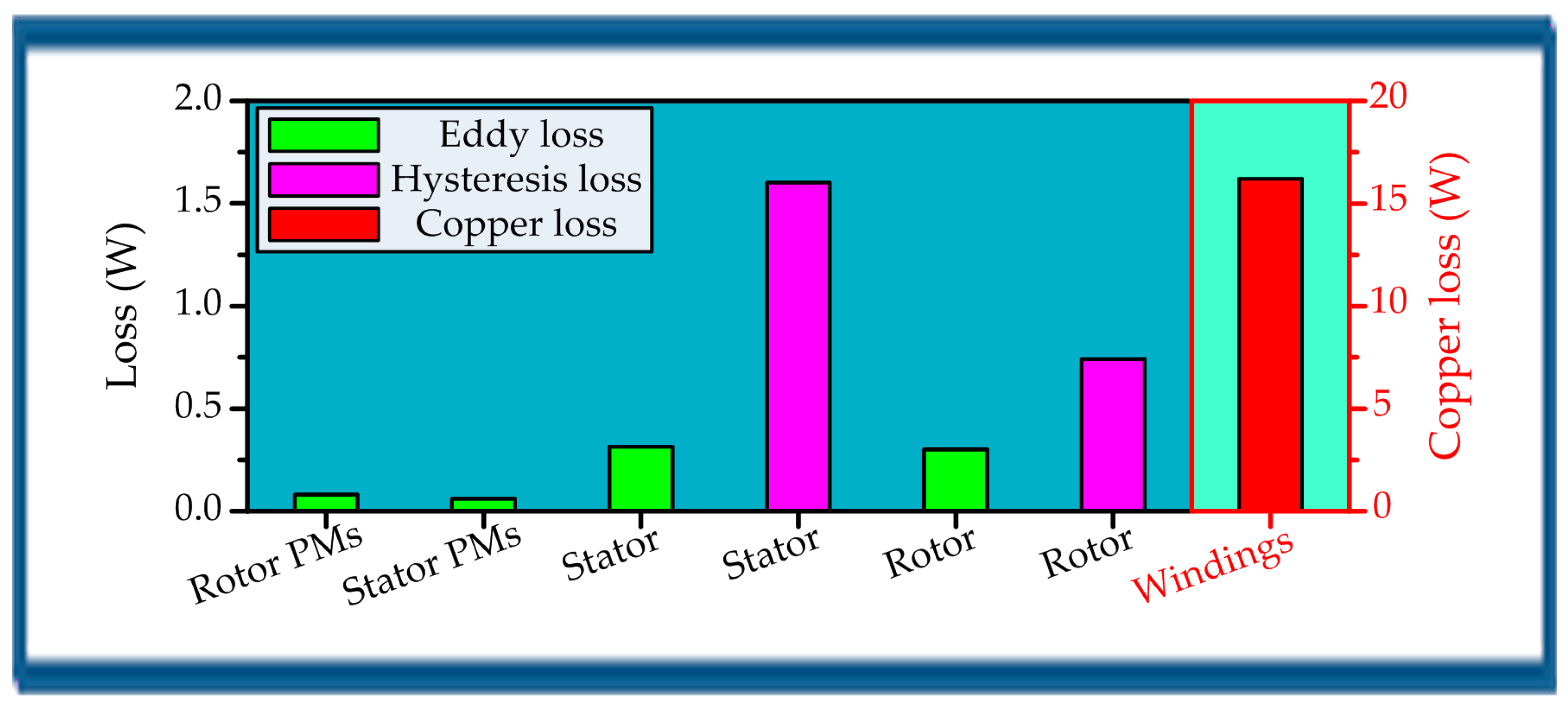
Figure 19 evaluates the losses of the two machines when they rotate at 120 r/min and output the maximum torque with
I = 3 A. It can be observed that the copper losses of the two machines are the same, because they with the same phase resistance are injected the same current. The copper loss is 16.2 W. Apart from the copper loss, the loss that is generated by each part in the proposed machine is a bit larger when compared with Machine I. In terms of each machine, the dominant iron loss is concentrated on the stator; the PM loss accounts for a small part in the total loss; the copper loss accounts for a considerable proportion in the total loss. The total loss of the proposed machine, Machine I is about 19.30 W, 18.75 W, respectively. Meanwhile, the corresponding efficiency is 92%, 91%, respectively. So, it can be known that although the total loss in the proposed machine is a bit larger than Machine I, the efficiency of the proposed machine is a bit higher than Machine I, because it can offer larger torque with the BFME and flux strengthening effect.
The comparative results are summarized in
Table 7 in order to make them clear. It can be seen that the electric load and speed of the two machines are the same, but the proposed DPME machine outperforms Machine I in many ways due to the BFME and flux strengthening effect. In terms of torque capability, the proposed machine can offer larger torque density than Machine I. But, the intensity of PM utilization in the proposed machine is a bit higher than Machine I.


