Isobaric Expansion Engines: New Opportunities in Energy Conversion for Heat Engines, Pumps and Compressors


1
Encontech B.V. ET/TE, P.O. Box 217, 7500 AE Enschede, The Netherlands
2
Chair of Fluid Process Engineering, Paderborn University, Pohlweg 55, 33098 Paderborn, Germany
3
Chair of Thermodynamics and Heat Engines, Gubkin Russian State University of Oil and Gas, Leninsky Prospekt 65, Moscow 119991, Russia
*
Author to whom correspondence should be addressed.
Energies 2018, 11(1), 154; https://doi.org/10.3390/en11010154
Submission received: 12 December 2017
/
Revised: 31 December 2017
/
Accepted: 4 January 2018
/
Published: 8 January 2018
(This article belongs to the Section I: Energy Fundamentals and Conversion)
Abstract
:Isobaric expansion (IE) engines are a very uncommon type of heat-to-mechanical-power converters, radically different from all well-known heat engines. Useful work is extracted during an isobaric expansion process, i.e., without a polytropic gas/vapour expansion accompanied by a pressure decrease typical of state-of-the-art piston engines, turbines, etc. This distinctive feature permits isobaric expansion machines to serve as very simple and inexpensive heat-driven pumps and compressors as well as heat-to-shaft-power converters with desired speed/torque. Commercial application of such machines, however, is scarce, mainly due to a low efficiency. This article aims to revive the long-known concept by proposing important modifications to make IE machines competitive and cost-effective alternatives to state-of-the-art heat conversion technologies. Experimental and theoretical results supporting the isobaric expansion technology are presented and promising potential applications, including emerging power generation methods, are discussed. It is shown that dense working fluids with high thermal expansion at high process temperature and low compressibility at low temperature make it possible to operate with reasonable thermal efficiencies at ultra-low heat source temperatures (70–100 °C). Regeneration/recuperation of heat can increase the efficiency notably and extend the area of application of these machines to higher heat source temperatures. For heat source temperatures of 200–600 °C, the efficiency of these machines can reach 20–50% thus making them a flexible, economical and energy efficient alternative to many today’s power generation technologies, first of all organic Rankine cycle (ORC).
1. Introduction
Heat-to-electricity conversion machines (engines) operating on Rankine cycle account for the lion’s share of worldwide power generation. The higher the temperature of the heat source, the more efficient, economical and compact is the engine. Vice versa, efficiency drops while cost and footprint rise with decreasing heat source temperature. For temperatures below 300 °C, water steam turns to be inefficient as a working fluid, and hence, alternative fluids with lower boiling temperatures must be applied. Such modified cycles are called Organic Rankine Cycles, or ORC [1,2]. When the heat source temperature is below 100 °C, the increased cost of ORC cycle installation makes the process uneconomical. A similar trend is valid for power range (i.e., size of the machines); large-scale Rankine cycle plants are the most efficient and economical, whereas mini-scale (less than 50 kW) and micro-scale (less than 1 kW) plants are unavailable on the market because of their high cost and low efficiency [3]. As a result, low-temperature heat and small-scale applications are not covered by the state-of-the-art technologies.
The heart and most expensive (up to 69% of capital cost [3,4]) and complex part of a Rankine cycle plant is the expansion machine, e.g., a turbine or a piston-based expander. The expansion machine converts energy of a hot, compressed steam (vapour) into mechanical energy. The development of new types of expansion machines and the improvement of the today’s well-known expanders is one of the main research directions in the Rankine cycle-based and ORC-based power generation [5,6].
An expansion machine, extracting work during polytropic (ideal case: isentropic) gas or vapour expansion is a key element of all state-of-the-art heat-to-power converters (heat engines)—gas or steam turbines, piston engines, etc. However, there exists another, less known, class of heat engines. In this class, there is no polytropic gas/vapour expansion accompanied by notable pressure fall. The Worthington direct-acting steam pump [7] and the Bush compressor [8] represent this type of engines. By convention, they can be called isobaric expansion (IE) machines, although, in some cases, the actual expansion process they perform can substantially deviate from isobaricity. In essence, the main distinguishing feature of these machines is the absence of a polytropic gas/vapour expansion stage in expansion machine, resulting in a simple, low-cost design. In addition to power generation, these engines are able to pump liquids and compress gases using heat directly, without any intermediate stages such as shaft power/electricity generation.
In spite of all these advantages, the technical application of these machines is very limited, mainly because of their low efficiency. Several thermo-compressors that employ the principle of isobaric expansion have been constructed and investigated in the 1970s, but their thermal efficiencies were rather disappointing. The compressor of Air Products and Chemicals achieved a thermal efficiency of not more than 5.4% at a hot temperature of over 550 °C (9% of Carnot efficiency) [9], compressors with hot temperatures above 625 °C built by McDonald Douglas corporation and Aerojet/Nimbus operated with 14.4% (20% of Carnot efficiency) and 18% (28% of Carnot efficiency) respectively [10,11,12].
In this paper, we propose significant changes to the original concepts of the Worthington steam pump and the Bush thermo-compressor, aiming to increase their efficiency to the levels comparable or even superior to modern heat engines, above of all ORC power plants. These modifications include the application of dense working fluids with high thermal expansion at high process temperature and low compressibility at low temperature instead of gases, new concepts for efficient heat regeneration/recuperation and further technical improvements. We provide experimental results obtained in a lab-scale unit to prove the technical feasibility of the proposed concepts. Moreover, thermodynamic simulations for a number of selected working fluids and operating conditions were carried out in order to display the capability of improved IE machines. Finally, some further technical modifications and potential application areas including emerging power generation methods are discussed.
2. Isobaric Expansion Machines
2.1. Worthington Direct-Acting Steam Pump
The most known examples of isobaric expansion machines are so-called Worthington’s or direct-acting steam pumps [7] invented and patented by Henry Worthington around 1841. Remarkably, such types of machines are still being produced and operated as boiler feed pumps, ship emergency pumps, etc., without any significant changes in the original design.
The basic principle of a so-called single-acting steam pump is shown in Figure 1. The pump consists of steam cylinder 1 and pumping cylinder 2, with steam piston 3 and a pumping piston 4 inside, correspondingly.
The pistons are rigidly connected by rod 5 and move together as a unit. The steam cylinder is equipped with steam inlet/admission valve 6 and outlet/exhaust valve 7 shown at the top. Accordingly, the pumping cylinder has inlet/suction valve 8 and outlet/discharge valve 9. The inlet and outlet valves of the steam cylinder are forcedly actuated; the valves of the pumping cylinder are self-acting.
When the inlet valve of the steam cylinder opens, steam enters the cylinder and moves the piston performing pumping stroke in the pumping cylinder. The valve remains open during the whole stroke, i.e., steam enters the cylinder at constant pressure and does not expand in the cylinder. Therefore, during the whole stroke, the pressure in the steam cylinder remains constant.
Such a process can be defined as an isobaric expansion. At the end of the stroke, the inlet steam valve closes and the outlet valve opens. The steam exhausts from the cylinder and the piston moves back under the pressure of liquid entering through the inlet valve the pumping cylinder. Therefore, the reciprocating motion of the piston unit is accompanied by pumping and suction of a liquid in the pumping cylinder.
The pump uses a very simple valves actuation system without a cut-off mechanism and has no crank gear and no flywheel.
Depending on the diameters of the steam and pumping pistons, the discharge pressure of the liquid to be pumped can be equal to, lower or higher than the steam pressure. The pump can operate at very high temperatures (up to 400 °C), pump liquids in a very broad range of viscosities and compress gases.
Direct acting pumps are very simple, reliable and cheap. They are probably the oldest machines on the market [13].
A remarkable feature of direct acting pumps is that they pump liquids directly by the use of heat without interposition of electricity and without a long sequence of energy transformations typical for conventional Rankine cycle installations such as conversion into rotary motion and electricity generation.
Obviously, any direct acting pump can also be used as a heat-to-shaft or electrical power converter. We believe that the simplest way to design such a process is to use a hydraulic circuit with a hydraulic motor. A functional scheme of such a power plant with a single-acting pump is shown in Figure 2.
Water is pumped by feed water pump 1 through recuperative heat exchanger (recuperator) 2 and heater (evaporator, boiler) 3 where it is heated and turned to steam. The steam is supplied to the steam cylinder of the direct acting pump performing the isobaric working stroke of the piston. The exhausted steam cools down and turns back into liquid in recuperator 2 and condenser 4. The energy of the liquid discharged from the pumping cylinder (ideally, it is a hydraulic oil) is converted to shaft power in a hydraulic circuit consisting of two high- and low-pressure hydraulic accumulators 5 and 6 and hydraulic motor 7 connected to a load. The pressure in high-pressure accumulator 6 is almost equal to the maximum delivery pressure of the pump. The pressure in the low-pressure accumulator 5 must be sufficient to move the piston of the pump back, displacing the spent steam from the cylinder.
Such a power plant has much in common with conventional Rankine cycle plants (boiler, condenser, feed water pump) being, however, much simpler and cheaper, since inexpensive mass-market hydraulic motors are used instead of turbines.
2.2. Bush Thermocompressor Based Expansion Machines
The isobaric expansion principle can be implemented without the feed pump necessary for the Worthington pump-based power plant shown in Figure 2. Such a pumpless converter can be built based on the ingenious concept of the so-called Bush compressor, or thermo-compressor, invented by V. Bush in 1939 [8]. Later on, various versions of thermo-compressor were proposed and extensively investigated [14,15,16,17,18,19]. The main direction of the research and development efforts was using the thermo-compressor as a source of mechanical power.
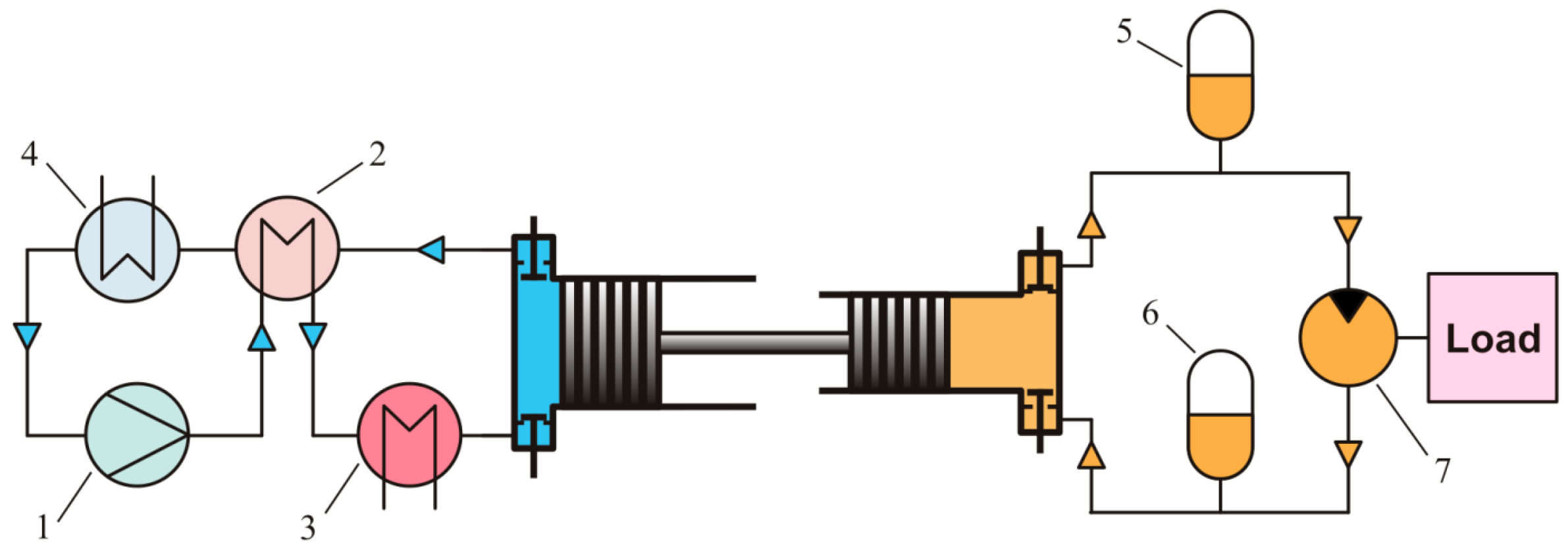
A conceptual sketch of a thermo-compressor-based power unit is shown in Figure 3. The converter consists of cylinder 1 filled with gas, with well-sealed piston 2 inside, so that the piston subdivides the internal volume of the cylinder into two—hot and cold—parts shown in rose and blue colours, correspondingly. Both parts are communicated through heater 3, regenerator 4 and cooler 5 connected in series. The regenerator plays here the same role as the recuperator of the direct acting pump shown in Figure 2. The piston can be set in reciprocating motion by means of sealed rod 6 and linear actuator 7.
The converter is equipped with diaphragm unit 8, the main part of which is a polymer flexible diaphragm separating the working fluid and hydraulic oil in the closed-loop hydraulic circuit. In fact, the diaphragm plays a role of the pumping piston in the direct-drive steam pump shown in Figure 2. The hydraulic circuit is similar to that shown in Figure 2. The circuit consists of two check valves 9, high- and low-pressure hydraulic accumulators 10 and 11, and hydraulic motor 12 connected to a load (e.g., an electric alternator).
In operation, the linear actuator sets the piston into a reciprocating motion. Moving down, the piston displaces some part of the working fluid from the cold to the hot part of the cylinder. The working fluid passes the cooler, the regenerator and the heater and heats up. Pressure in the converter rises, and a part of the working fluid is displaced to the diaphragm unit. The diaphragm transmits the pressure to hydraulic oil which flows through the discharge check valve, high-pressure accumulator and hydraulic motor to the low-pressure accumulator. The hydraulic motor converts the oil energy to shaft power.
Moving up, the piston displaces the hot, compressed working fluid through the heater, regenerator and cooler back to the cold part of the cylinder. The pressure in the cylinder drops down. As soon as it becomes lower than the charge pressure in the low-pressure accumulator, oil forces the working fluid from the diaphragm unit back to the cylinder. Afterwards, the cycle repeats.
The regenerator plays a very important role: it stores heat from the previous cycle and uses it to preheat the working fluid in the next cycle increasing thermodynamic efficiency of the heat conversion. Theoretically, in case of perfect regeneration possible for ideal gases (working fluid returns to the hot space of the converter with the temperature of the hot space), the efficiency of the converter can be equal to the Carnot cycle efficiency.
Low-power (less than 1 kW) machines can have a very simple design, without the external heater-regenerator-cooler loop. In this case, the upper part of the cylinder is heated, while the lower one is cooled. A small gap between the piston and cylinder plays the role of the regenerator. In some cases, the regenerator can also be placed inside the piston. Most of the thermo-compressors were built according to these two schemes.
Hydraulic power output permits the heat-to-mechanical-energy converter to be improved. In particular, it makes the actuation of the piston very convenient: some part of the hydraulic power produced is used for the actuation by means of any type of hydraulic mover, e.g., reciprocating (hydraulic cylinder) or rotary hydraulic motor equipped with a crank mechanism [20]. There also exist some advanced versions of the thermo-compressor with a self-oscillating piston [21]. In this case, the compressor does not need any actuator and, most important, it does not need any sealing; leakages and seal friction losses are totally eliminated.
In spite of the attractiveness of the isobaric expansion machines, all attempts to develop a ready-to-market thermo-compressor have failed. It is commonly assumed that the thermo-compressor represents a particular type of the Stirling engine [22] with typical disadvantages [23,24] inherent in all Stirling engines.
First of all, the thermo-compressor is very sensitive to the so-called dead volumes. Indeed, the heater, cooler, regenerator and all connection pipelines have internal volumes, which are detrimental to the efficiency and the power density. A reason is that heating of the working fluid in the heater results not only in useful work generation but also in substantial compression of working fluid in the dead volumes. This harmful effect increases rapidly with the machine power. The power (i.e., volume) of the engine is proportional to the third power of the size, whereas the heat exchanger area is proportional only to the second power of the size. In practice, this means that the internal volume of the heat exchangers grows much faster than the heat exchangers area. The bigger the size of the machine, the more difficult is the heat supply.
The second drawback is the low thermal expansion of gases. The power density of the machine is proportional to the difference between the maximum and the minimum cycle pressures. A high pressure difference can be obtained only at a very high temperature of the heat source and/or at a high initial pressure of the gaseous working fluid in the machine. Both conditions require expensive, heat resistant alloys and thick walls worsening heat exchange. Sealing of gases at high pressure is difficult and can cause additional friction losses. Reaching higher power density by increasing the cycle frequency results in enhanced flow and frictional losses, generation of frictional heat and wear of sliding/rubbing parts.
One of the ways to overcome these drawbacks is to use fluids with high thermal expansion at a high cycle temperature and low compressibility at a low cycle temperature. Fluids that undergo a phase change from liquid to gas during the cycle as well as supercritical fluids near the critical point belong to this category. For brevity, we call these fluids dense working fluids.
Since liquids have much lower compressibility than gases, the negative influence of dead volume filled with a liquid can be reduced considerably.
During the phase change, thermal expansion of dense working fluids at practically interesting operating pressures of 10–100 bar is significantly higher (one-two order of magnitude) than that for gases. As a result, the heat source temperature, initial pressure and speed/frequency of the cycle required for the same specific power can be decreased in the machine with a dense working fluid.
Boiling and condensation processes together with higher thermal conductivity of liquids compared to gases facilitate heat transfer, because of the decreased heat transfer resistance on the working fluid side. In addition, sealing of liquids is much simpler as compared to gases. The higher thermal conductivity and heat capacity of liquids facilitates the removal of the heat of friction and thus reduces wear of rubbing parts.
Despite the fact that the direct-acting pumps used liquid (water) from the very beginning, the first attempts to use liquid in Bush-type machines started not until the seventies of the last century [14,25,26,27]. Unfortunately, this interesting development was not followed up in spite of encouraging theoretical data and expectations [22]. We may assume that low thermal efficiency and technical complexity of the engines used were the reasons.
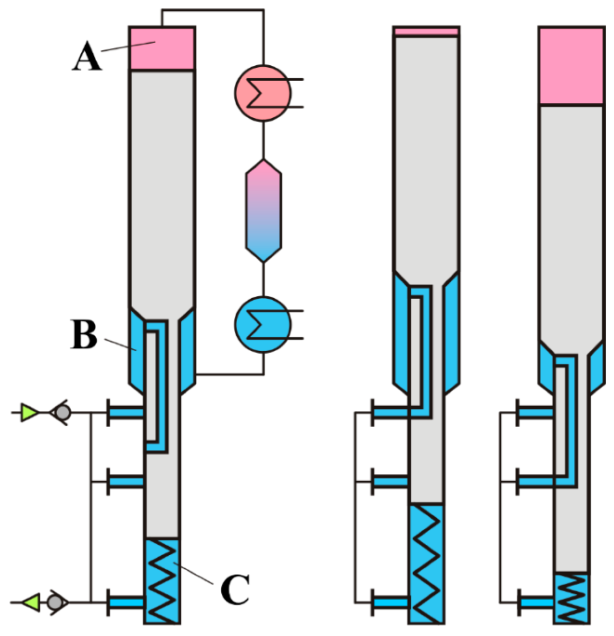
As in the case of gaseous working fluids, it is also possible to realise self-oscillating piston designs for machines with dense working fluids [28,29,30,31]. A functional scheme of one of such self-driven machines is shown in Figure 4.
For simplicity, the diaphragm unit and the hydraulic circuit are not shown; so the machine is depicted as a pump for the liquid used as the working fluid. The pump consists of a differential cylinder with a differential piston inside. The piston divides the internal volume of the cylinder into three parts: heated (hot) part A and two cold parts B and C. The machine is equipped with an external cooler, regenerator and heater. In non-operating condition, the piston is maintained in the middle position inside the cylinder by means of a spring, shown in the lower part of the cylinder.
The lower part of the cylinder has three fluid ports communicated by a manifold. The manifold is equipped with two self-acting (suction and discharge) non-return valves. There is a passage inside the piston allowing the piston to operate as a valve: in the lower and upper positions of the piston, the passage communicates the part B of the cylinder with the part C. The parts A and B are always communicated through the cooler, regenerator and heater.
When the working fluid is heated and turns into vapour, pressure in the parts A and B rises forcing the piston down and compressing the spring. In addition, the piston displaces the working fluid from the cold part B through the cooler, regenerator and heater to the hot part A causing a further rise of pressure and forcing the piston down. The liquid from the part C is displaced into the manifold and then discharged through the lower non-return valve to the delivery line. When the piston reaches the lower position, it stops and communicates parts A, B and C, equalising the pressure inside the cylinder. During this stage, some amount of liquid from the part A is also forced to the manifold and discharged through the valve to the delivery line. Afterwards, the spring pushes the piston up, disconnecting the parts B and C. Moving up, the piston displaces the working fluid back from the hot part A to the cold part B. Going through the regenerator and the cooler, the vapour turns into liquid and the pressure in the parts A and B drops below the pressure in the part C, manifold and suction line. Liquid from the suction line enters the part C, forces the piston up and expands the spring.
In the upper position, the passage in the piston communicates the parts B and C, again equalising the pressure. Liquid from the suction line and the manifold enters the part B and then the part A through the cooler, regenerator and heater, heats up and turns into vapour. At the same time, the spring pulls the piston down; the piston disconnects parts B and C, the pressure rises again starting the next cycle.
3. Experimental Investigation
We studied the operation of a self-driven small-scale Bush-type engine/pump with R134a refrigerant as working fluid using the experimental set-up shown in Figure 5. The basic principle of operation of this machine is shown in Figure 4. Due to low power the machine does not need external heat exchangers. Side surface of the cylinder wall is sufficient to supply and reject heat when working fluid flows through the annular gap between the cylinder and displacer. A part of the annular gap in between heated and cooled parts plays the role of regenerator. To enhance heat exchange, the side surface of displacer is well-developed by means of plurality of small grooves.
The setup included IE machine 1 with a cylinder inner diameter of 30 mm and a displacer stroke length of 40 mm provided with heating jacket 2 (heater) and cooling jacket 3 (cooler). Hot water with temperature varying between 50 and 90 °C circulating in the heating, upper jacket was used as the heat source. The lower part of the cylinder was cooled with cold (25 °C) water circulating through a cooling jacket. Pressure pulses generated by the engine were transmitted through a rubber diaphragm of diaphragm unit 4 to hydraulic oil circulating in a hydraulic circuit which included two non-return valves 4, two high- and low-pressure 160 mL hydraulic accumulators 6 and 7 and needle throttling valve 8. The valve imitated a load throttling the oil flow from the high-pressure to the low-pressure accumulator. The pressures before and after the throttle valve as well as pressure inside the cylinder were measured by pressure transmitters PT (Sendo JF302 5MPa gauge, Ninghai Sendo Sensor Co., Ltd., Hangzhou, China, with 0.5% accuracy and 4 ms response time).
Independently, the pressures were controlled by 6 MPa Empeo manometers with 1.6% accuracy (are not shown) installed in parallel with the pressure transmitters. The oil flow rate was measured by gear flow transmitter FT (Profimess VM-01.0.1 with accuracy of ±2%) installed in the line after the throttle valve. All transmitters had 4–20 ma output to avoid influence of cable lengths. Signal of the transmitters were processed and displayed by 12 bits PicoLog 1000 data acquisition system with 1 MS/s sampling rate. Temperature of hot and cooling water were measured by two 3 mm shielded K-types thermocouples, pre-calibrated in the range of 0–100 °C.
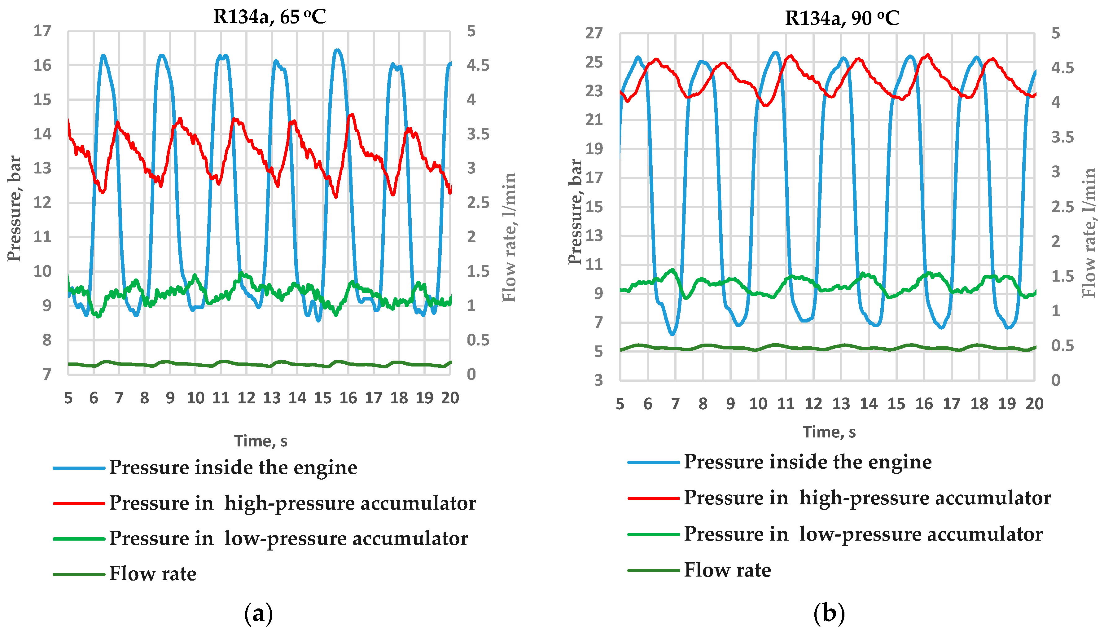
The machine demonstrated a self-starting ability and very stable, repeatable operation. The results for two different hot water temperatures are shown in Figure 6.
As can be seen, the machine can pump liquid with a considerable pressure differences (up to 20 bar) even at such low temperature differences. At higher temperatures, the generated pressure difference can reach tens and hundreds of bar, depending on the working fluids. The measured power was up to 20 W. The power was calculated as the product of the measured flow rate of the hydraulic oil and the pressure difference over the throttling valve. The heat supply to the engine was not measured in the presented setup, so that the thermal efficiency could not be evaluated directly. Some estimates of the efficiency were made by replacing the heating jacket with an aluminium cast electric heater. It was found that the thermal efficiency could be as high as 50% of the Carnot efficiency even without careful thermal insulation of the hot engine parts and without other measures to decrease heat losses. The efficiency was estimated as a ratio of the engine power to electric power supplied to the heater. Both the efficiency and power strongly depend on the temperatures, the load (resistance to the oil flow) and the amount of the working fluid in the engine. The estimated efficiency and power are very promising taking into account the temperatures and size of the investigated engine.
A remarkable feature of the engine is the ability to adapt to the load: at a given heat source temperature, the engine can deliver the same hydraulic power at different combinations of pressures and flow rates depending on the load. When the pressure in the high-pressure accumulator increases, the engine immediately generates a higher pressure and a lower flow rate. Such a self-adaptation is very useful for practical implementation.
4. Efficiency of Isobaric Expansion Machines with Dense Working Fluids
4.1. Thermodynamic Modelling
To estimate the efficiency of the machines described in the previous sections, thermodynamic models where developed for both the Worthington-type machine and the Bush-type engine. Here, the basic equations used for the calculation of the engines efficiencies are presented.
4.1.1. Worthington-Type Engine
The thermal efficiency is defined as the work produced during a full cycle in relation to the supplied heat:
In a simplified model of the Worthington-type single-acting engine (cf. Figure 2), the cycle starts with vaporised working fluid entering the steam cylinder. The pressure increases up to the maximum cycle pressure at constant (minimum) volume of the fluid in the steam cylinder. We assume the initial volume in the steam cylinder to be equal to zero, therefore isochoric pressurisation does not apply and pressure in the steam cylinder rises to the maximum value immediately. As soon as the maximum pressure is established, further supply of steam results in expansion of the fluid in the steam cylinder and, consequently, in expansion work. When reaching the maximum volume, the pressure inside the steam cylinder is reduced by a throttled exhaust of working fluid at constant steam cylinder volume. Afterwards, the steam cylinder volume is reduced back to its minimum while working fluid leaves the steam cylinder at constant low pressure. The expansion-compression work performed by the piston during this process is:
In this equation, and are the pressures during the expansion and compression processes, and is the change of steam volume in the cylinder. The pumping work, assuming a reversible process with negligible changes in kinetic and potential energies, can be determined as:
where is the total mass of the working fluid pumped per cycle, is the enthalpy of the working fluid per unit mass, is the temperature at the inlet of the pump and is the discharge temperature of the pump. The discharge pump temperature can be determined assuming an isentropic pump operation.
The net value of the work produced during the cycle is found as:
The working fluid is heated up in a heater from the pump discharge temperature (usually slightly above the temperature of the cooler) to the desired inlet temperature of the steam cylinder. This heat transfer process can be assisted by a recuperative heat exchanger, recovering a part of the heat the working fluid exhausted from the steam cylinder. In this case, the duty of the heater depends on the performance of the recuperator, i.e., on the temperature of the working fluid at the outlet of the recuperator :
In order to determine from the energy balance of the recuperator, the inlet temperature of the countercurrent stream coming from the steam cylinder is necessary. It was assumed that the pressure of the steam exhausted from the steam cylinder decreases from the high cycle pressure to the low cycle pressure in a throttle located before the recuperator for technical reasons. The exhaust valve of the steam cylinder may play the role of the throttle. This pressure reduction process was considered as a Joule—Thompson expansion. Neglecting the changes in kinetic and potential energy, the temperatures in the cylinder and at the inlet of the recuperator are related by an equation ensuring no enthalpy change in this process:
The calculated temperatures and were always above the saturation temperature; therefore, no condensation was taken into account in Equation (6).
Finally, temperature and pressure in the cylinder, and or before the exhaust valve during the pressure reduction process and backstroke of the piston were determined from the energy balance for the adiabatic process:
where is the fluid density. Although the amount of working fluid in the cylinder reduces the energy, the balance equation (Equation (7)) is the same as that for adiabatic expansion of a fluid of constant mass.
Equations (2)–(7) together with an equation for the recuperation efficiency (see e.g., Equation (11) below) permit calculation of the amount of heat supplied by the heater and ultimately the thermal efficiency (Equation (1)).
4.1.2. Bush-Type Engine
The useful work generated during the cycle is:
where the total engine volume consists of the volumes of the hot space, , the cold space, and the regenerator which does not change during engine operation. The interdependence of temperatures and volumes of the individual engine compartments and the pressure is expressed by the equation for the total mass of the working fluid:
The heat supply to the hot part is determined from the energy balance of this space, neglecting changes of kinetic and potential energies:
is the energy required to heat the displaced working fluid from the regenerator outlet temperature (or low cycle temperature , if there is no regenerator) to the high cycle temperature . A method to estimate the performance of the regenerator is presented in the subsequent section. With Equations (8) and (10), the thermal efficiency can be evaluated.
The modelling of the Bush-type engine is explained in more detail in [32].
4.2. Estimation of the Regeneration/Recuperation Efficiency
The performance of the recuperative and regenerative heat exchangers (or recuperator and regenerator) in both considered engine types strongly affects the efficiency of the respective engine. As there is no functional difference between regeneration and recuperation, we will use the term regenerator for both these types of heat exchangers.
In an ideal regenerator, the heat removed from the working fluid during its cooling would be completely returned to the working fluid during heating. This, however, is unrealistic because of thermodynamic and technical limitations of actual heat transfer processes. For instance, different heat capacities of the working fluid during heating and cooling make it impossible to achieve perfect regeneration. This is particularly true for cycles in which dense working fluids are evaporated at a high pressure (and temperature) and condensed at a lower pressure. The heat of condensation cannot be used to provide the latent heat for evaporation in such a case. In addition, a positive driving temperature difference between the hot and cold stream in a heat exchanger must be maintained.
A reasonable value of this temperature difference for a real heat exchanger needs to be found in accordance to desired performance and available space. To estimate the regeneration efficiencies for the, composite curves [33] for the heating and cooling processes are determined. They give the amount of energy required to obtain a certain temperature change over the investigated temperature range. The regeneration potential can be found by shifting the heating curve (receiving heat) sufficiently far to maintain a minimum temperature difference between the cooling curve (providing heat) and the heating curve. Figure 7 shows examples of such composite curves. The dashed red line illustrates the heating curve resulting in a minimum temperature difference of 0 K which represents the theoretical maximum of regeneration. The solid red line is an example for a positive minimum temperature difference. The regeneration efficiency is defined as the ratio of heat to be recovered in the regenerator to the total energy to be supplied to the engine:
The higher the minimum temperature difference is, the lower is the regeneration efficiency. The regeneration efficiency of the Bush-type engine can be higher than that of the Worthington-type engine, as the condensation in the Bush-type engine occurs not only during the isobaric process, but also during the isochoric process at decreasing pressure. Hence, compared to the Worthington-type process, a larger portion of the heat of condensation can be recovered.
4.3. Simulation Results
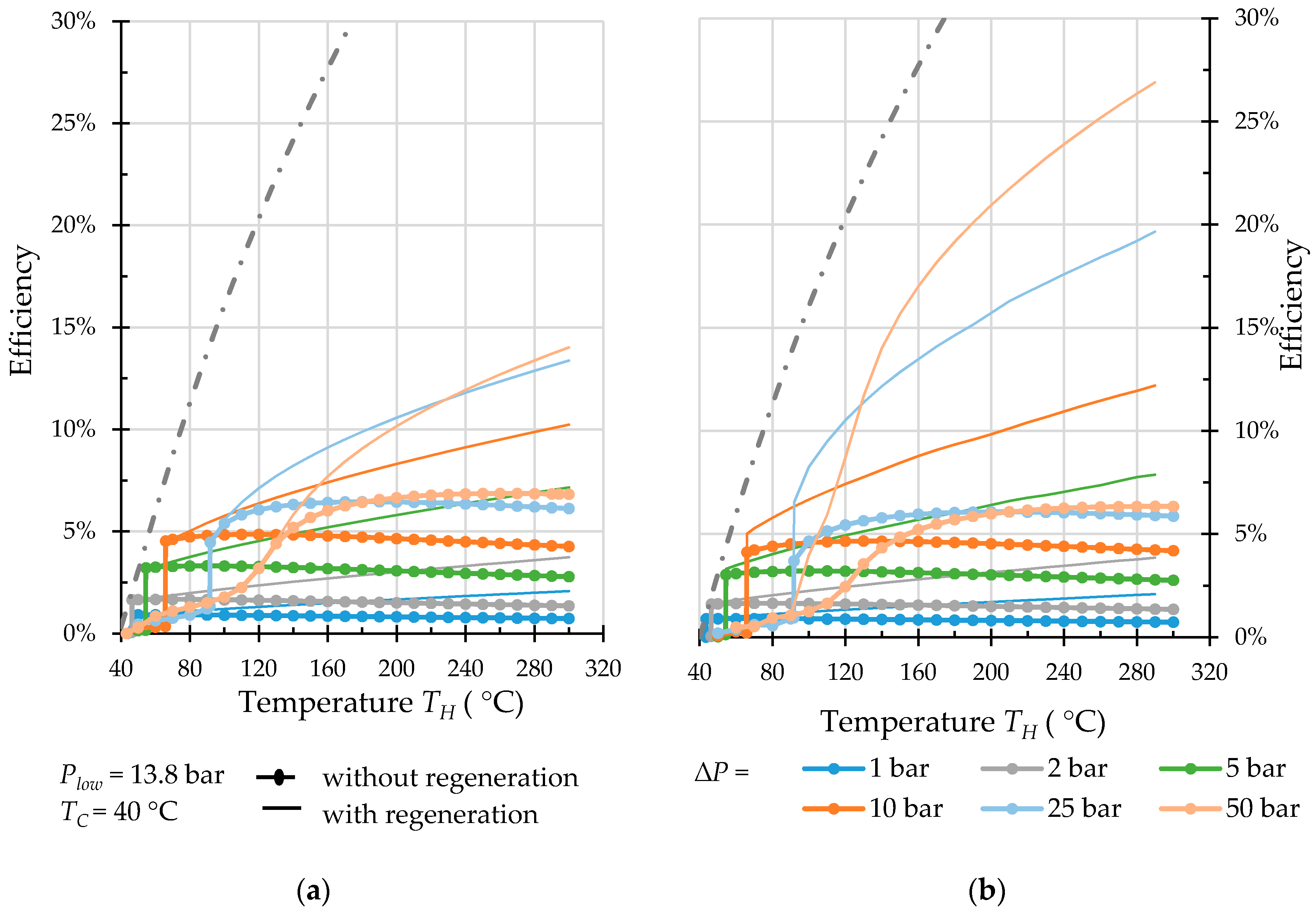
The models of Worthington-type and Bush-type engines together with the approach to estimate the regeneration efficiency described above (Equations (1)–(11)) were implemented in a MATLAB environment to study the influence of different operating pressures and working fluids on the efficiency of both engine types. The simulations were performed for two distinctive cases: (1) the simplest case without regeneration and (2) a regenerative operation, assuming that a minimum temperature difference of 5 K in the regenerator is realised. Dead volumes were not taken into account, even though they may have a negative effect on the efficiency of Bush-type engines. Different working fluids were investigated. Thermodynamic properties of the working fluids were obtained from the NIST Standard Reference Database 23. Results obtained for water, propane, pentane, R32 refrigerant and carbon dioxide are discussed below.
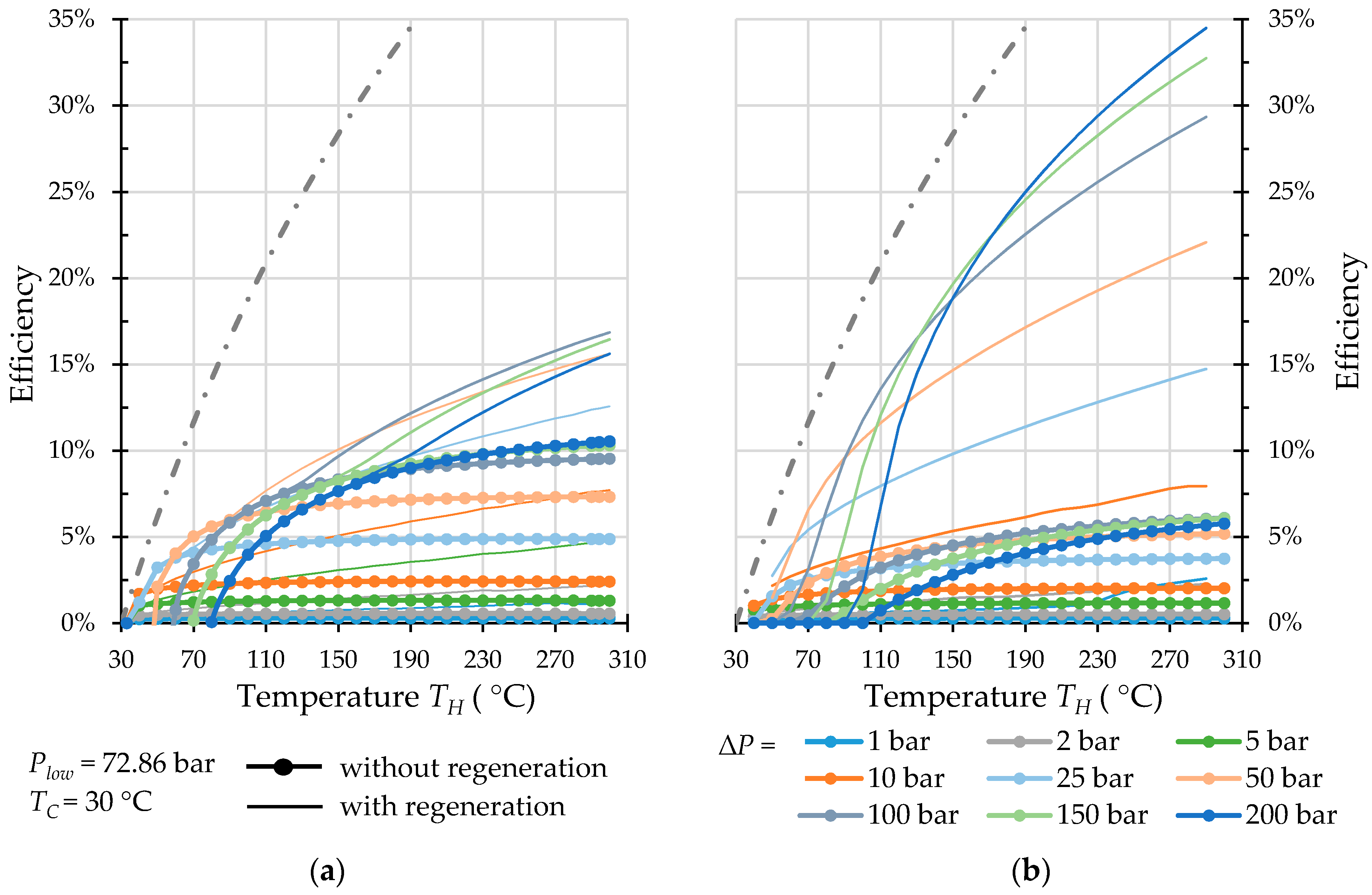
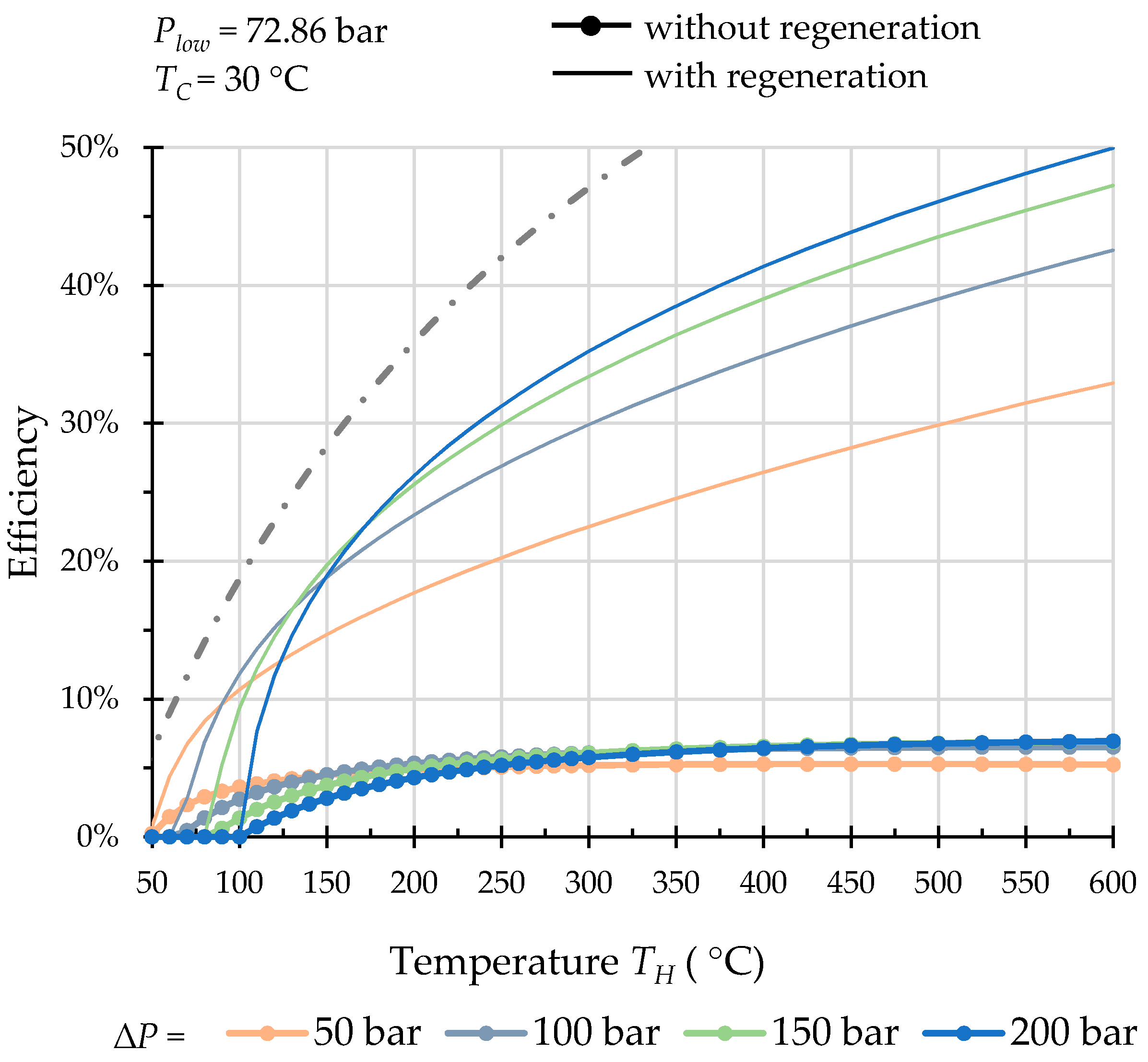
The minimum cycle temperature (temperature of the heat sink) was chosen as TC = 40 °C for all the working fluids except carbon dioxide. For carbon dioxide, it was chosen as 30 °C, i.e., below the critical temperature of 30.98 °C in order to guarantee its liquid state at low temperature and any pressure throughout the cycle. The maximum/high cycle temperature was varied from 50 °C to 600 °C for carbon dioxide and from 50 °C to 300 °C for the other working fluids. The low pressure Plow was chosen slightly above the saturation pressure for each fluid at low temperature to exclude undesired boiling at low cycle temperature, but not lower than 1.0 bar, depending on which of the two pressures is higher. The difference between the high and low pressure ∆P was varied in a range of 1.0 to 50 bar. For R32 refrigerant and carbon dioxide, the pressure difference range was extended to 200 bar. Selected results are shown in Figure 8, Figure 9, Figure 10, Figure 11 and Figure 12. Figure 13 shows results for carbon dioxide at very high (up to 600 °C) heat source temperature to estimate a potential of this technology for high-temperature applications. The dash-and-dot line in each graph indicates the Carnot efficiency.
For both types of engines, stepwise increase in the efficiency is observed at certain temperatures of the heat source. These heat source temperatures correspond to the saturation temperatures in subcritical area. The very low efficiencies at temperatures below the saturation temperature are found for engine operation with working fluid being in liquid state.
At first sight, the results for non-regenerative operation of the two engine types under comparison are almost equivalent. For R32 and CO2, better efficiencies are obtained for the Worthington-type machine. These results, however, are overestimated, as the assumption of incompressible liquids, used in the calculation of the Worthington-type engine, fails for these two fluids under the investigated conditions.
Operation without regeneration is particularly interesting for low-temperature applications. For instance, an engine with propane as working fluid (Figure 10) can generate a 10 bar pressure amplitude at a heat source temperature of roughly 70 °C with an efficiency of nearly 5%. With pentane, a heat source temperature of 58 °C is sufficient to generate a 1 bar pressure amplitude with an efficiency of 4.3% (Figure 9). It is worth noting that the Carnot efficiency for this process conditions is 5.4%. Thus, the relative to the Carnot efficiency is above 80%.
With the heat regeneration, the higher the temperature is, the more pronounced is the influence of regeneration for both types of engines, and the Bush-type engine outperforms the Worthington-type engine for all working fluids under investigation.
With and without regeneration, water demonstrates a very poor performance for both types of engines in the studied temperature range. For Worthington-type engines, the influence of recuperation in case of water is almost negligible, whereas for propane, the efficiency can be doubled at high temperatures. For Bush-type engines, the regeneration in operation with propane can increase the efficiency almost fivefold.
At very low temperatures, the influence of the regeneration is poor. Effective heat regeneration for dense working fluids in low temperature range can be problematic. A reason is that heat released during condensation of working fluid at low temperature and pressure cannot be used to evaporate it at higher temperature and pressure of the isobaric expansion stage. Moreover, the latent heat constitutes a considerable part of the whole amount of energy supplied during heating and released during cooling. The latent heat of water condensation, for example, accounts for about 90% of the whole heat released during the cooling from 300 °C to 40 °C at normal pressure. Poor regeneration, resulting in the low efficiency, explains a relatively limited area of application of water-based Worthington pumps.
For other fluids, the fraction of latent heat at studied process conditions is around 50%; therefore, a considerable part of heat can be regenerated.
Unfortunately, the incomplete regeneration is typical also for working fluids in a supercritical state near the critical point. In this case, the problem is caused by a difference in heat capacities of the working fluid at different pressures used during its heating and cooling in the regenerator.
In contrast to Worthington-type machines, in Bush-type machines, both the evaporation and the condensation of working fluid partially take place at variable pressure. The evaporation occurs simultaneously with a pressure rise; the condensation is accompanied by a drop of pressure. Such a regime is favourable for the regeneration. As it can be seen, even with water (Figure 8), the regeneration is much more pronounced resulting in an efficiency rise. Efficiency in case of propane (Figure 10) can compete with that of ORC [34].
5. Discussion
5.1. General
The term “isobaric expansion” is essentially used as a term rather than an exact characterisation of the process, just to distinguish from isentropic expansion processes. As a matter of fact, the process pressure may vary, depending on the load; for instance, in case of gas compression, pressure changes during the cycle.
Isobaric expansion machines represent a peculiar type of heat-to-mechanical energy converters, which are characterised by the absence of a gas expansion stage. Practically all well-known today’s heat engines (piston IC-engines, gas, steam and ORC turbines, etc.) fall into a different group, performing polytropic gas expansion.
5.2. Bush- and Worthington-Type Engines—Results and Comparison
Bush-type and Worthington-type engines are two examples of simple and inexpensive machines performing isobaric expansion cycle. At high temperatures, the Bush-based machines outperform the Worthington-based ones. In a low-temperature range, where the influence of heat recuperation is negligible, a choice between these two types is not evident. At first glance, the Worthington-based machines are more complex because of the valve system, piston and valves sealing and the need for a pump. However, they are totally insensitive to the dead volume. This means an unlimited choice of types and sizes of heat exchangers and, therefore, an ability to supply heat in any form from any possible source.
The Bush-type machines are simpler, since they do not require a valve system or a separate pump. Moreover, they can be made self-driven. Self-driven machines need neither an actuator and nor connection rod sealing. As a result, both leakages of working fluid and seal friction losses are eliminated. In addition, self-actuation is more energy efficient. Nevertheless, the actuated machines can be preferable in some cases. They are easy to control and a synchronization of several machines is very simple.
All the designs of Bush-type machines known from the literature concern applications at relatively small power (less than 1 kW), with heat addition and rejection through the surface of the engine cylinder and a regenerator located in the displacer or in the gap between the displacer and the cylinder. Medium- and large-scale machines require more powerful heat exchangers being placed outside the cylinder. Ten to twenty years ago such engines with external heat exchangers were not feasible due to too large internal volume of the then existing heat exchangers. However, a recent revolution in the field of very compact heat exchangers [35,36] makes it possible to build medium-scale and even large-scale engines with external heat exchangers. State-of-the-art microchannel/printed circuit heat exchangers permit the heater, regenerator and cooler to be combined into a compact single integral unit with minimal internal (dead) volume. A further integration of such a composite heat exchanger into the piston-cylinder unit is an option to decrease the dead volume of the machine even more.
Bush-type machines also can have great potential in high-temperature application; no need of high-temperature sealing makes that especially attractive. This potential is also supported by the high efficiencies obtained for carbon dioxide (Figure 13).
The found efficiencies at low temperature differences were above 80% of the Carnot efficiencies. These results are very encouraging, taking into account the simplicity and low price of the machines for harvesting ultra-low grade heat, e.g., waste and geothermal heat sources, low temperature solar energy, such as solar ponds, etc. [37,38].
5.3. Potential Improvements
5.3.1. Regeneration
A very promising way to improve the regeneration for both types of engines is to use an approach successfully employed in cryogenics, namely the replacement of single-component working fluids with multi-component ones with different boiling temperatures [39,40]. By this means, boiling and condensation of the working fluid take place at variable temperatures. As a result, both boiling and condensing some part of the working fluid is possible in the regenerator rather than in the cooler and heater. In other words, the heat of condensation of a high-boiling component can be used for the evaporation of low-boiling components, and thus, this part of the latent heat of the working fluid can be regenerated.
The expected effect depends on the mixture composition, initial temperature and pressure as well as on the temperature and pressure ratios. Taking into account the fraction of latent heat in the total amount of heat supplied, the resulting rise in efficiency can be remarkable. However, selection and/or design of appropriate multicomponent working fluids require very serious research efforts.
5.3.2. Dead Volumes
At first glance, the very impressive efficiencies of Bush-type engines might look too optimistic, since the dead volume of the machines has not been taken into account. In fact, the greater part of this dead volume arises due to internal volumes of the heater, cooler and regenerator. A harmful influence of the heat exchanger internal volumes can be reduced, if necessary, by decreasing the energy density of the machines. For instance, a machine with a working volume (displacement) of one liter and a cycle frequency of 1 Hz generates the same power as a machine with a displacement of two liters and a cycle frequency of 0.5 Hz. To deliver this power, both machines require heat exchangers with the same internal volume. However, in case of the machine with the lower speed and higher displacement, the dead volume of the heat exchangers related to the total volume of the machine is twice as low. Decrease of power density appears to be unimportant in view of the generally high power density of these machines compared to other engines.
Unfortunately, the influence of the regenerator dead volume cannot be minimised in the same way. The volume of the regenerator is directly proportional to the volume displaced in the machine. A possible solution to reduce the regenerator dead volume is to replace the regenerator by a recuperative heat exchanger in a duplex arrangement as shown in Figure 14. In this scheme, two identical machines, working in counter-phase, share a common recuperator. When one machine is in the heating process, the other machine provides heat during its cooling process (and vice versa). In contrast to a regenerator, the heat is here directly transferred to the working fluid and the recuperator size is no longer proportional to the volume displaced in the machine.
5.3.3. Non-Isothermal Heat Supply
The temperature of the heating agent in the heater decreases due to heat exchange with the working fluid. This is especially important in the case of indirect heat supply by means of different heat transfer fluids (heat carriers) such as pressurised water, heat transfer oils or liquid metals. In fact, the indirect isothermal heating requires an infinite circulation rate of the heat carrier whereas non-isothermal heat supply makes it possible to decrease the circulation rate to economically viable levels. The higher this temperature decrease, the more efficient and economical is the use of the heat source. Therefore, heat supply to the engines can be highly non-isothermal.
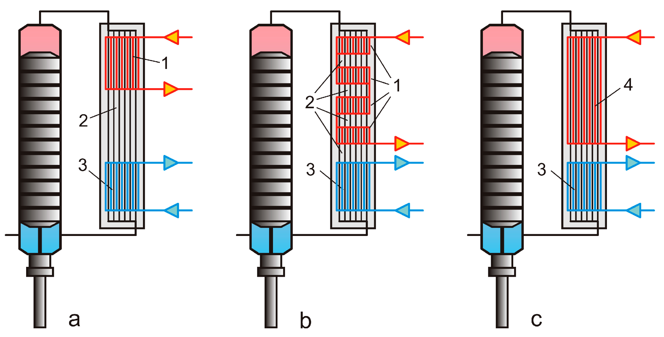
Figure 15a shows a simplified layout of an isobaric expansion machine with the heater, regenerator and cooler combined in one integral printed circuit heat exchanger. Vertical black, red and blue lines signify here working fluid, heat carrier and cooling agent channels correspondingly.
A highly non-isothermal heat supply implies a high temperature difference between the hottest and coldest parts of the heater. As a result, during the backstroke (when the piston moves upwards) the hot working fluid, displaced from the hottest part of the cylinder and heater, heats up the heat carrier at the lower, colder part of the heater shown in Figure 15a. The heat is carried away instead of being absorbed by the regenerator. This leads to a poor efficiency of the machine and an inefficient use of the heat source.
The problem can be solved by means of a different design of the heat exchanger shown in Figure 15b. Here, the heater is divided into several parts with regenerative sections in between. The bigger the temperature difference, the more heater/regenerator pairs are necessary.
A limiting (and the most interesting) case of such a design is shown in the Figure 15c, where the heater and regenerator are merged into a single unit, combining their functions. This regenerative heater is a special type of heat exchanger which can also accumulate heat of both the working fluid and heat carrier.
At low frequency operation typical for isobaric expansion engines, a non-stationary, periodic supply of heat carrier can be used in combination with such a heat exchanger. This is particularly convenient for the duplex (two engines working in counter phase) engine layout. The heat carrier is pumped through the heat exchanger only during the working stroke (i.e., during a half cycle, when the piston moves downwards). During the backstroke, the flow of heat carrier is diverted to the adjacent engine. This method is ideally suited for actuated machines, where the actuators of the pistons and the heat carrier diverting valve can be synchronised.
The reasoning discussed above is equally valid for engine coolers.
5.4. Hydraulic Output and Applications
The hydraulic output of the machines under consideration may have a clear advantage for many applications in comparison to state-of-the-art energy conversion technologies. This is especially important for pumping and compression, resulting in elimination of several energy conversion stages together with the corresponding equipment (electric generator and motor, power transmission, etc.). As a result, numerous sources of low-grade and waste heat can be used directly and cost-effectively for pumping and compression.
One of the most interesting applications, especially for the Bush-type machines, is the pumping of liquids which can also be used as working fluids. Such pumps can be applied for pumping of liquefied gases, light hydrocarbons, heat transfer fluids, etc. Since these machines do not need lubrication, they can be of great interest also in cryogenic applications.
The convenience to operate between any desired pressure levels makes them a very promising heat-driven alternative to conventional refrigerant compressors in vapour compression refrigerating machines.
The conversion of the hydraulic power output of the machines to shaft power by means of an oil-hydraulic loop outlined above is just one out of many possible options. It was selected because of the availability of low-cost, off-the-shelf industrial hydraulic components. The main part of the hydraulic loop—a positive displacement hydraulic motor—can reach an efficiency of above 90% in a broad power range and shows excellent energy density and reliability. A broad spectrum of low- medium- and high-speed hydraulic motors is available in a power range from several tens of watts to several hundred kilowatts.
An obvious advantage of oil-hydraulic output is the possibility to generate shaft power at the most convenient speed and torque without an additional transmission. Moreover, one engine can drive several motors with different speeds and torques. Vice versa, one hydraulic motor can be driven by several engines as well. In the latter case, these engines can operate at different temperatures of the heater and cooler and even use different working fluids.
A direct conversion of the working fluid energy to shaft power, without transmitting the pressure to oil, is also of a great interest. Unfortunately, hydraulic motors for liquids with low viscosity and poor lubricating ability are missing on the today’s market. Perhaps the experience gained in the area of water-hydraulic power utilisation systems can be used for a development of such motors. A so-called “pump as turbine” (PAT) technology uses rotodynamic (centrifugal) pumps as turbines, i.e., one of the types of hydraulic motors in micro- and pico-hydro power as well as a reverse osmosis energy utilisation [41,42]. As the oil-hydraulic motors, centrifugal pumps are inexpensive mass-market machines with relatively high maximum efficiencies (up to 80–85%). Today, such a reverse operation of centrifugal pumps with water is well studied. The operation with other fluids in the turbine mode requires further investigations. The main disadvantage of centrifugal pumps/turbines is a remarkable drop of efficiency with a decreasing power range and in a part-load operation.
5.5. Emerging Technologies
Although it is very convenient to use hydraulic motors in combination with a rotary electric generator in case of electricity generation, alternative approaches are possible. Examples include a direct conversion of pressure to electricity by means of a piezoelectric pressure-to-electricity transmitter [43,44,45], different electrokinetic effects associated with electricity generation by forcing liquids through membranes [46,47], electrohydrodynamic electrostatic generators [48], reverse electrowetting [49], etc. All these methods make it possible to eliminate electric alternators, as well as to decrease the number of moving parts of the machines.
5.6. Final Remarks
It is worth noting that in this paper, only simple basic schemes of isobaric expansion engines and very limited experimental and theoretical data are presented. As in the case of Rankine cycle plants, numerous modifications of the schemes and working fluids are possible.
6. Conclusions
Isobaric expansion is a very promising energy conversion technology. Isobaric expansion cycles show excellent efficiency (up to 80% of the Carnot efficiency) at ultra-low heat source temperatures (as low as 70–100 °C). At higher temperatures, heat regeneration increases the efficiency remarkably, up to 30–35% at 300 °C. The efficiency at 600 °C can reach as high as 50%, showing a tendency to rise further with temperature. Replacement of single-component working fluids with multi-component mixtures could potentially result in a further efficiency rise in all temperature ranges, due to improved heat regeneration. The elimination of both polytropic gas expansion process and machine results in the substantial simplification of the engine design and cost. Moreover, some of these engines (self-driven types) do not need seals; this eliminates any leakage and frictional losses. All this together with a wide choice of output speed/torque without gearboxes can make the isobaric expansion technology a simple and low-cost alternative to the present ORC-based plants and other state-of-the-art energy conversion systems based on the conventional heat engines.
The potential area of application of isobaric expansion machines is not limited to power generation. They can serve as very efficient, simple and cost-effective heat-driven pumps and compressors. A remarkable feature in this case is the ability to generate very high pressure differences even at relatively low temperatures.
Acknowledgments
The experimental results presented in this publication were made possible by NPRP grant # 8-547-2-222 from the Qatar National Research Fund (a member of Qatar Foundation). The findings achieved herein are solely the responsibility of the authors.
Author Contributions
Maxim Glushenkov and Alexander Kronberg proposed and developed the technology and engine designs, invented the presented technical solutions, worked out the theoretical background and performed experiments. The modelling as well as the analysis of the computational results was performed by Torben Knoke and Eugeny Y. Kenig. All the authors participated in writing the paper.
Conflicts of Interest
The authors declare no conflicts of interest.
Nomenclature
| h | Specific enthalpie (J/kg) |
| m | Mass (kg) |
| P | Pressure (bar) |
| Q | Heat (J) |
| V | Volume (m3) |
| W | Work (J) |
| Greek Symbols | |
| η | Thermal efficiency (-) |
| ρ | Density (kg/m3) |
| Subscripts | |
| C | Cold, Cooling |
| E | Expansion chamber (steam cylinder) |
| H | Hot, Heating |
| min | Minimum |
| out | Outlet |
| P | Pump |
| R | Regenerator, Recuperator |
| tot | total |
References
- Macchi, E.; Astolfi, M. (Eds.) Organic Rankine Cycle (ORC) Power Systems: Technologies and Applications; Woodhead Publishing: Duxford, UK, 2016; p. 698. [Google Scholar]
- Invernizzi, C. Closed Power Cycles: Thermodynamic Fundamentals and Applications; Springer: London, UK; New York, NY, USA, 2013; p. 264. [Google Scholar]
- Lemmens, S. A perspective on cost and cost estimation techniques for organic Rankine cycle systems. In Proceedings of the 3rd International Seminar on ORC Power Systems, Brussels, Belgium, 12–14 October 2015. [Google Scholar]
- Quoilin, S.; Van Den Broek, M.; Declaye, S.; Dewallef, P.; Lemort, V. Techno-economic survey of Organic Rankine Cycle (ORC) systems. Renew. Sustain. Energy Rev. 2013, 22, 168–186. [Google Scholar] [CrossRef]
- Bao, J.; Zhao, L. A review of working fluid and expander selections for organic Rankine cycle. Renew. Sustain. Energy Rev. 2013, 24, 325–342. [Google Scholar] [CrossRef]
- Guoquan, Q.; Hao, L.; Saffa, R. Expanders for micro-CHP systems with organic Rankine cycle. Appl. Therm. Eng. 2011, 31, 3301–3307. [Google Scholar]
- Nesbitt, B. Handbook of Pumps and Pumping; Elsevier Science: Oxford, UK, 2006; p. 424. [Google Scholar]
- Bush, V. Apparatus for Compressing Gases. U.S. Patent 2,157,229, 17 July 1935. [Google Scholar]
- Gibson, B.M.; Hornbeck, C.J.; Longworth, R.C.; Harmison, L.T. Bypass Gas Actuated Thermocompressor as an Implantable Artificial Heart Power Source. In Proceedings of the 6th Intersociety Energy Conversion Engineering Conference, Boston, MA, USA, 3 August 1971; Paper No. 719043. pp. 310–316. [Google Scholar]
- Martini, W.R.; Johnston, R.P.; Goranson, R.B.; White, M.A. Development of a Simplified Stirling Engine to Power Circulatory Assist Devices. In Proceedings of the 3rd Intersociety Energy Conversion Engineering Conference, Boulder, CO, USA, 13–17 August 1968; Paper No. 689102. pp. 733–749. [Google Scholar]
- Martini, W.R. The Thermocompresor and its Application to Artificial Heart Power. In Proceedings of the 4th Intersociety Energy Conversion Engineering Conference, Washington, DC, USA, 22–26 September 1969; Paper No. 69015. pp. 107–114. [Google Scholar]
- Moise, J.C. Thermocompressor Powered Artificial Heart Assist System. In Proceedings of the 12th Intersociety Energy Conversion Engineering Conference, Newark, DE, USA, 17 August 1975; Paper No. 779017. pp. 112–118. [Google Scholar]
- Karassik, I.J.; Messina, J.P.; Cooper, P.; Heald, C.C. Pump Handbook, 3rd ed.; McGraw-Hill: New York, NY, USA, 2001. [Google Scholar]
- Walker, G.; Senft, J.R. Free Piston Stirling Engines; Springer: Berlin/Heidelberg, Germany, 1985. [Google Scholar]
- Brodjanskij, V.M. Compressor for Compression of Gases; USSR Autor’s Sertificat 244544. 1967. Available online: http://russianpatents.com/patent/230/2303162.html (accessed on 14 October 2017).
- Martini, W.R. Stirling Cycle Amplifying Machine. U.S. Patent 3,513,659, 2 February 1968. [Google Scholar]
- Martini, W.R. Stirling Cycle Amplifying Machine. U.S. Patent 3,604,821, 13 August 1969. [Google Scholar]
- Buck, K.E. Modified Stirling Cycle Engine—Compressor Having a Freely Reciprocable Displacer Piston. U.S. Patent 3,678,686, 20 February 1970. [Google Scholar]
- Eder, F.X. Gas Compressor Directly Driven through Heat Input. U.S. Patent 4,751,819, 19 October 1984. [Google Scholar]
- Ohrt, D. Process and Device for Conveying Boilable Liquids. U.S. Patent 4,954,048, 30 December 1988. [Google Scholar]
- Baumgardner, A.R. Stirling Cycle Machine with Self-Oscillating Regenerator. U.S. Patent 3,484,616, 1 February 1968. [Google Scholar]
- Walker, G. Stirling Engines; Clarendon Press: Oxford, UK, 1980; p. 532. [Google Scholar]
- Edwards, M.J.; Peterson, R.B. Reciprocating thermocompressor performance with non-ideal component characteristics. Proc. Inst. Mech. Eng Part A J. Power Energy 2007, 221, 459–472. [Google Scholar] [CrossRef]
- Kongtragool, B.; Wongwises, S. Thermodynamic analysis of a Stirling engine including dead volumes of hot space, cold space and regenerator. Renew. Energy 2006, 31, 345–359. [Google Scholar] [CrossRef]
- Huffman, F.N. Tidal Regenerator Heat Engine. U.S. Patent 3,657,877, 1 February 1971. [Google Scholar]
- Hagen, K.G.; Huffman, F. N.; Ruggles, A.E. Expansion Tidal Regenerator Heat Engine. U.S. Patent 3,986,360, 6 June 1975. [Google Scholar]
- Yarger, D.; Beck, M.; Peterson, R. Experimental Study of a Mesoscale Two-Phase Thermocompressor. In Proceedings of the 4th International Energy Conversion Engineering Conference and Exhibit (IECEC), San Diego, CA, USA, 26–29 June 2006. AIAA 2006-4014. [Google Scholar]
- Glushenkov, M.; Kronberg, A. Regenerative Heat to Mechanical Energy Converter with Dense Working Fluid. In Proceedings of the 16th International Stirling Engine Conference, Bilbao, Spain, 24–26 September 2014; pp. 177–186. [Google Scholar]
- Glushenkov, M.; Kronberg, A. Heat to Mechanical Energy Converter. WO Patent Application No. PCT/EP2012/064094, 18 July 2012. [Google Scholar]
- Oyewunmia, O.A.; Kirmsea, C.J.W.; Haslam, A.J.; Müller, E.A.; Markides, C.N. Working-fluid selection and performance investigation of a two-phase single-reciprocating-piston heat-conversion engine. Appl. Energy 2017, 186, 376–395. [Google Scholar] [CrossRef]
- Kirmsea, C.J.W.; Oyewunmia, O.A.; Taleb, A.I.; Haslam, A.J.; Markides, C.N. A two-phase single-reciprocating-piston heat conversion engine: Non-linear dynamic modelling. Appl. Energy 2017, 186, 359–375. [Google Scholar] [CrossRef]
- Knoke, T.; Kenig, E.Y.; Kronberg, A.; Glushenkov, M. Model-based analysis of novel heat engines for low-temperature heat conversion. Chem. Eng. Trans. 2017, 57, 499–504. [Google Scholar]
- Kemp, I.C. Pinch Analysis and Process Integration: A User Guide on Process Integration for the Efficient Use of Energy; Elsevier: Oxford, UK, 2007. [Google Scholar]
- Bu, X.; Wang, L.; Li, H. Performance analysis and working fluid selection for geothermal energy-powered organic Rankine-vapor compression air conditioning. Geotherm. Energy 2013, 1. [Google Scholar] [CrossRef]
- Hesselgreaves, J.E. Compact Heat Exchangers; Selection, Design and Operation; Elsevier: Pergamon, Turkey, 2001; p. 416. [Google Scholar]
- Zochuri, B. Compact Heat Exchangers: Selection, Application, Design and Evaluation; Springer: Cham, Switzerland, 2017; p. 559. [Google Scholar]
- Date, A.; Akbarzadeh, A. Theoretical study of a new thermodynamic power cycle for thermal water pumping application and its prospects when coupled to a solar water pond. Appl. Therm. Eng. 2013, 58, 511–521. [Google Scholar] [CrossRef]
- Date, A.; Ghaisas, S.V.; Date, A.; Akbarzadeh, A. Investigating the prospects of using novel thermal power pump cycle coupled with reverse osmosis system for water desalination. In Proceedings of the 3rd International Conference on Environment Energy and Biotechnology, Bangkok, Thailand, 18–19 December 2014; Volume 70, pp. 132–136. [Google Scholar]
- Venkatarathnam, G. Cryogenic Mixed Refrigerant Processes; Springer: Berlin, Germany, 2010; p. 262. [Google Scholar]
- Boiarski, M.J.; Brodianski, V.M.; Longsworth, R.C. Retrospective of Mixed-Refrigerant Technology and Modern Status of Cryocoolers Based on One-Stage, Oil-Lubricated Compressors. Adv. Cryog. Eng. 1998, 43, 1701–1708. [Google Scholar]
- Vasanthakumar, P. Investigation of centrifugal pump as Turbine: A review report. Int. J. Eng. Res. Technol. 2014, 3, 2287–2292. [Google Scholar]
- Agarwal, T. Review of pump as turbine (PAT) for micro-hydropower. Int. J. Emerg. Technol. Adv. Eng. 2012, 2, 163–169. [Google Scholar]
- Martini, W.R. The Stirling engine piezoelectric (STEPZ) power source concept for space applications. Trans. Am. Nucl. Soc. 1972, 15, 607. [Google Scholar]
- White, M.A.; Mc Donnel Douglas Astronautics Company. Proof-of Principle Investigation of 300 W(E) Stirling Engine Piezoelectric (STEPZ) Generator; Final Technical Report; National Technical Information Service: Springfield, VA, USA, 1973. Available online: http://www.dtic.mil/dtic/tr/fulltext/u2/768690.pdf (accessed on 14 October 2017).
- Martini, W.R. Stirling Engine Power System and Coupler. U.S. Patent 3,822,388, 26 March 1973. [Google Scholar]
- Malik, M.J. Stirling Cycle Drive for an Electrokinetic Transducer. U.S. Patent 3,400,281, 27 November 1964. [Google Scholar]
- Catalano, J.; Bentien, A.; Østedgaard-Munck, D.N.; Kjelstrup, S. Efficiency of electrochemical gas compression, pumping and power generation in membranes. J. Membrane Sci. 2015, 478, 37–48. [Google Scholar] [CrossRef]
- Xie, Y.; Bos, D.; de Vreede, L.J.; de Boer, H.L.; van der Meulen, M.J.; Versluis, M.; Sprenkels, A.J.; van den Berg, A.; Eijkel, J.C.T. High-efficiency ballistic electrostatic generator using microdroplets. Nat. Commun. 2014, 5, 3575. [Google Scholar] [CrossRef] [PubMed]
- Krupenkin, T.; Taylor, A.J. Reverse electrowetting as a new approach to high-power harvesting of mechanical energy. Nat. Commun. 2011, 2, 448. [Google Scholar] [CrossRef] [PubMed]
Figure 1.
Scheme of a single-acting Worthington steam pump. 1—steam cylinder, 2—pumping cylinder, 3—steam piston, 4—pumping piston, 5—connecting rod, 6—steam inlet valve, 7—steam outlet valve, 8—liquid inlet valve, 9—liquid outlet valve.
Figure 1.
Scheme of a single-acting Worthington steam pump. 1—steam cylinder, 2—pumping cylinder, 3—steam piston, 4—pumping piston, 5—connecting rod, 6—steam inlet valve, 7—steam outlet valve, 8—liquid inlet valve, 9—liquid outlet valve.
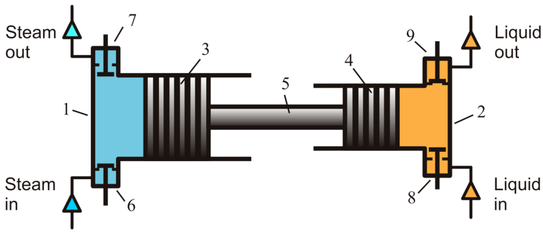
Figure 2.
Scheme of a Worthington pump-based power plant producing shaft power. 1—feed water pump, 2—heat recuperator, 3—evaporator, 4—condenser, 5—high-pressure hydraulic accumulator, 6—low-pressure hydraulic accumulator, 7—hydraulic motor.
Figure 2.
Scheme of a Worthington pump-based power plant producing shaft power. 1—feed water pump, 2—heat recuperator, 3—evaporator, 4—condenser, 5—high-pressure hydraulic accumulator, 6—low-pressure hydraulic accumulator, 7—hydraulic motor.

Figure 3.
Scheme of Bush thermo-compressor-based shaft-power unit. 1—cylinder, 2—piston, 3—heater, 4—regenerator, 5—cooler, 6—connecting rod, 7—linear actuator, 8—diaphragm unit, 9—non-return valves, 10—high-pressure accumulator, 11—low-pressure accumulator, 12—hydraulic motor.
Figure 3.
Scheme of Bush thermo-compressor-based shaft-power unit. 1—cylinder, 2—piston, 3—heater, 4—regenerator, 5—cooler, 6—connecting rod, 7—linear actuator, 8—diaphragm unit, 9—non-return valves, 10—high-pressure accumulator, 11—low-pressure accumulator, 12—hydraulic motor.
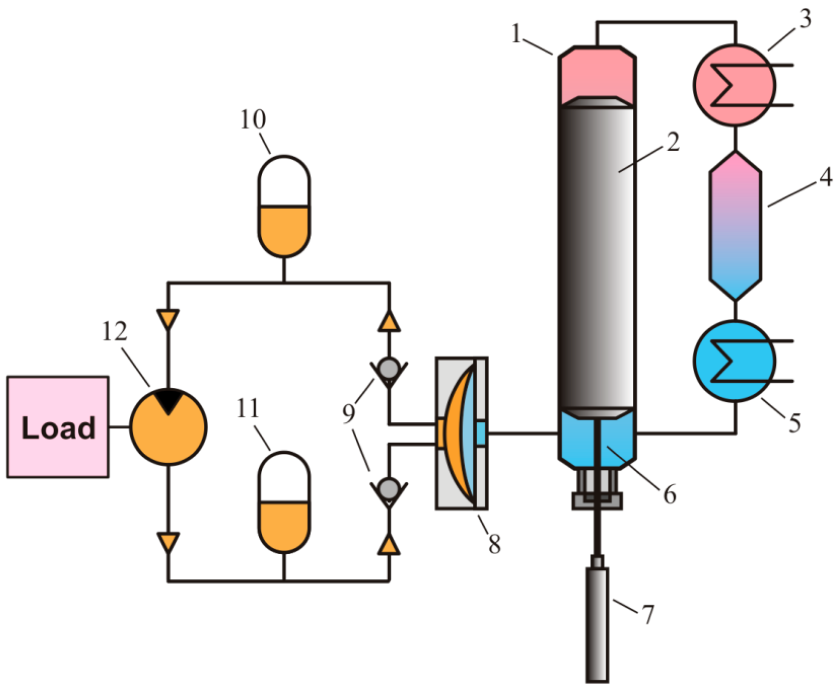
Figure 4.
Scheme of Bush-type self-driven machine; A—hot part, B and C—cold parts with the displacer in intermediate (left) and two extreme positions.
Figure 4.
Scheme of Bush-type self-driven machine; A—hot part, B and C—cold parts with the displacer in intermediate (left) and two extreme positions.

Figure 5.
Scheme of the experimental setup. 1—IE engine, 2—heating jacket, 3—cooling jacket, 4—diaphragm unit, 5—non-return valves, 6—high-pressure accumulator, 7—low-pressure accumulator, 8—throttle valve, PT—pressure transmitters, FT—flow transmitter.
Figure 5.
Scheme of the experimental setup. 1—IE engine, 2—heating jacket, 3—cooling jacket, 4—diaphragm unit, 5—non-return valves, 6—high-pressure accumulator, 7—low-pressure accumulator, 8—throttle valve, PT—pressure transmitters, FT—flow transmitter.
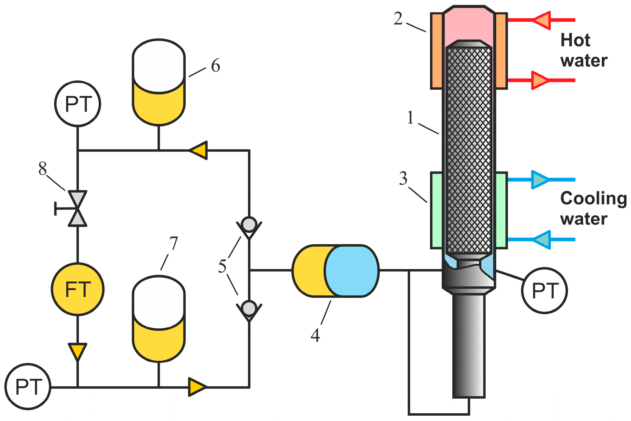
Figure 6.
Examples of pressure change and pumped flow rate in the self-driven Bush-type engine; working fluid: R134a; temperature of the cooler: 25 °C; temperature of the heater: 65 °C (a) and 90 °C (b).
Figure 6.
Examples of pressure change and pumped flow rate in the self-driven Bush-type engine; working fluid: R134a; temperature of the cooler: 25 °C; temperature of the heater: 65 °C (a) and 90 °C (b).

Figure 7.
Example of composite curves during isobaric cooling and heating at different pressures; (QC)′, (QR)′ and (QH)′ are shown for the theoretical maximum of regeneration, whereas (QC), (QR) and (QH) correspond to a real situation with the positive minimum temperature difference.
Figure 7.
Example of composite curves during isobaric cooling and heating at different pressures; (QC)′, (QR)′ and (QH)′ are shown for the theoretical maximum of regeneration, whereas (QC), (QR) and (QH) correspond to a real situation with the positive minimum temperature difference.
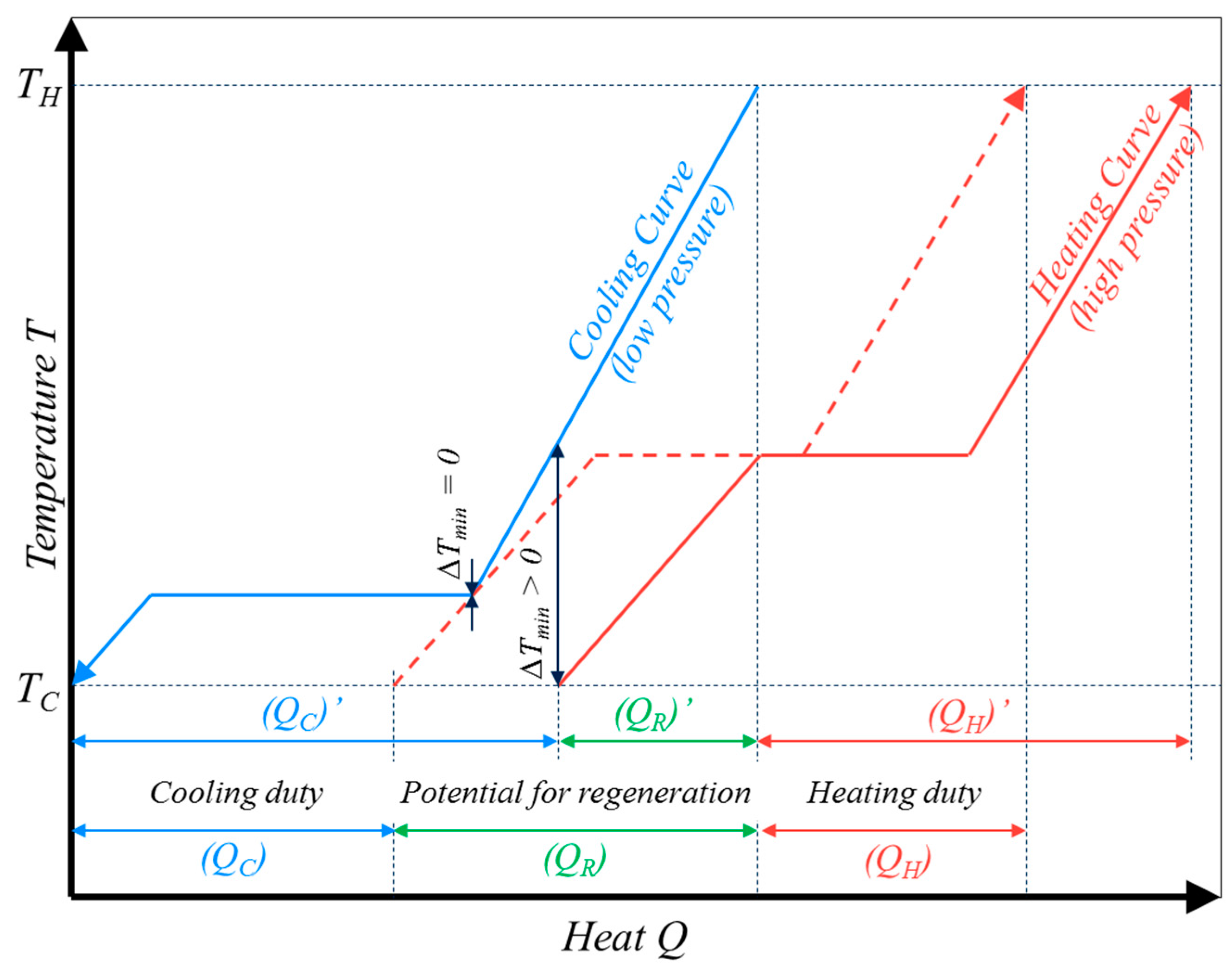
Figure 8.
Efficiency of regenerative Worthington-type machine (a) and Bush-type machine (b) operated with water.
Figure 8.
Efficiency of regenerative Worthington-type machine (a) and Bush-type machine (b) operated with water.
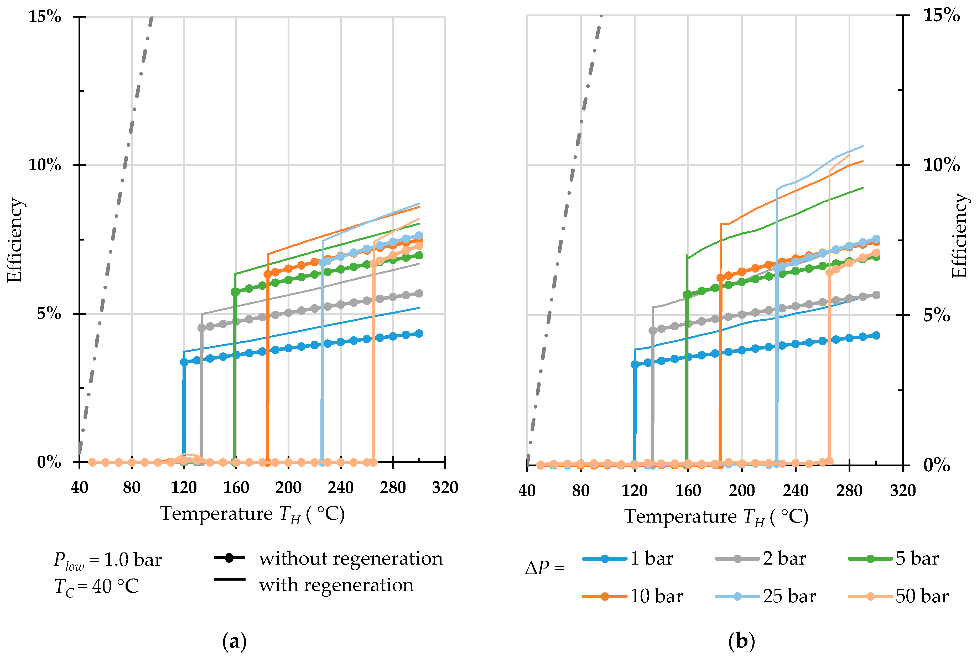
Figure 9.
Efficiency of regenerative Worthington-type machine (a) and Bush-type machine (b) operated with pentane.
Figure 9.
Efficiency of regenerative Worthington-type machine (a) and Bush-type machine (b) operated with pentane.
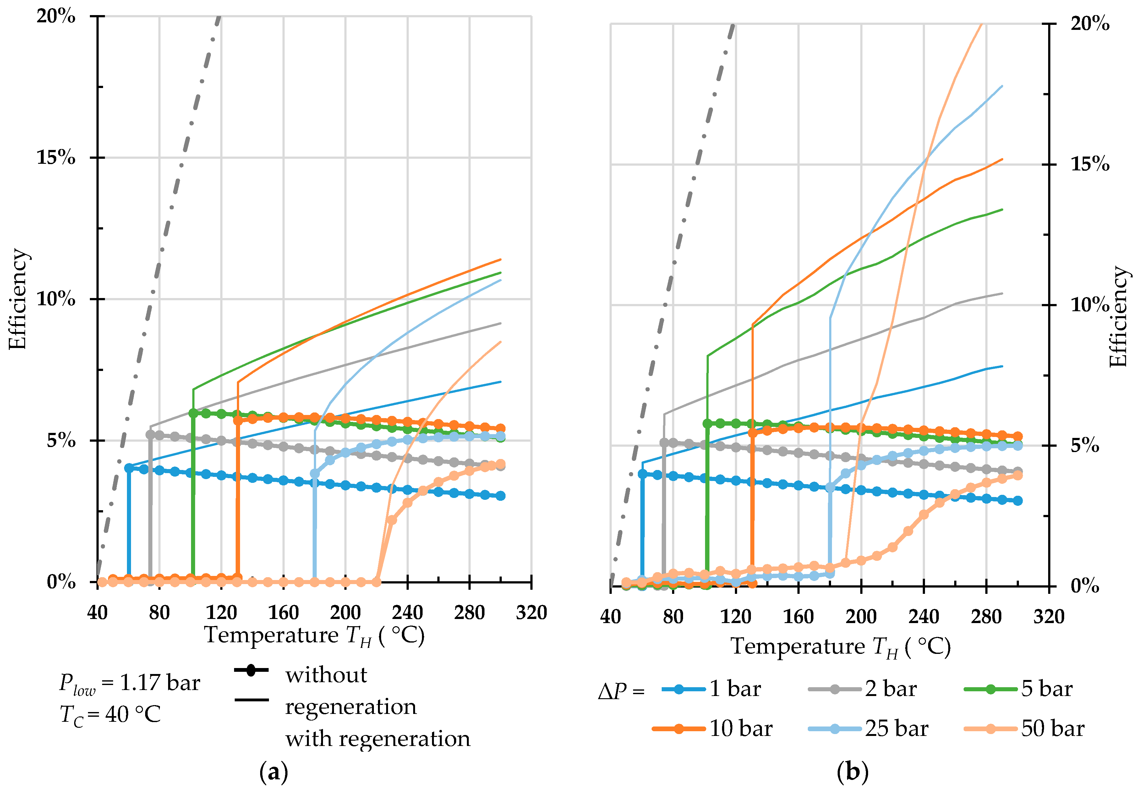
Figure 10.
Efficiency of regenerative Worthington-type machine (a) and Bush-type machine (b) operated with propane.
Figure 10.
Efficiency of regenerative Worthington-type machine (a) and Bush-type machine (b) operated with propane.

Figure 11.
Efficiency of regenerative Worthington-type machine (a) and Bush-type machine (b) operated with refrigerant R32.
Figure 11.
Efficiency of regenerative Worthington-type machine (a) and Bush-type machine (b) operated with refrigerant R32.
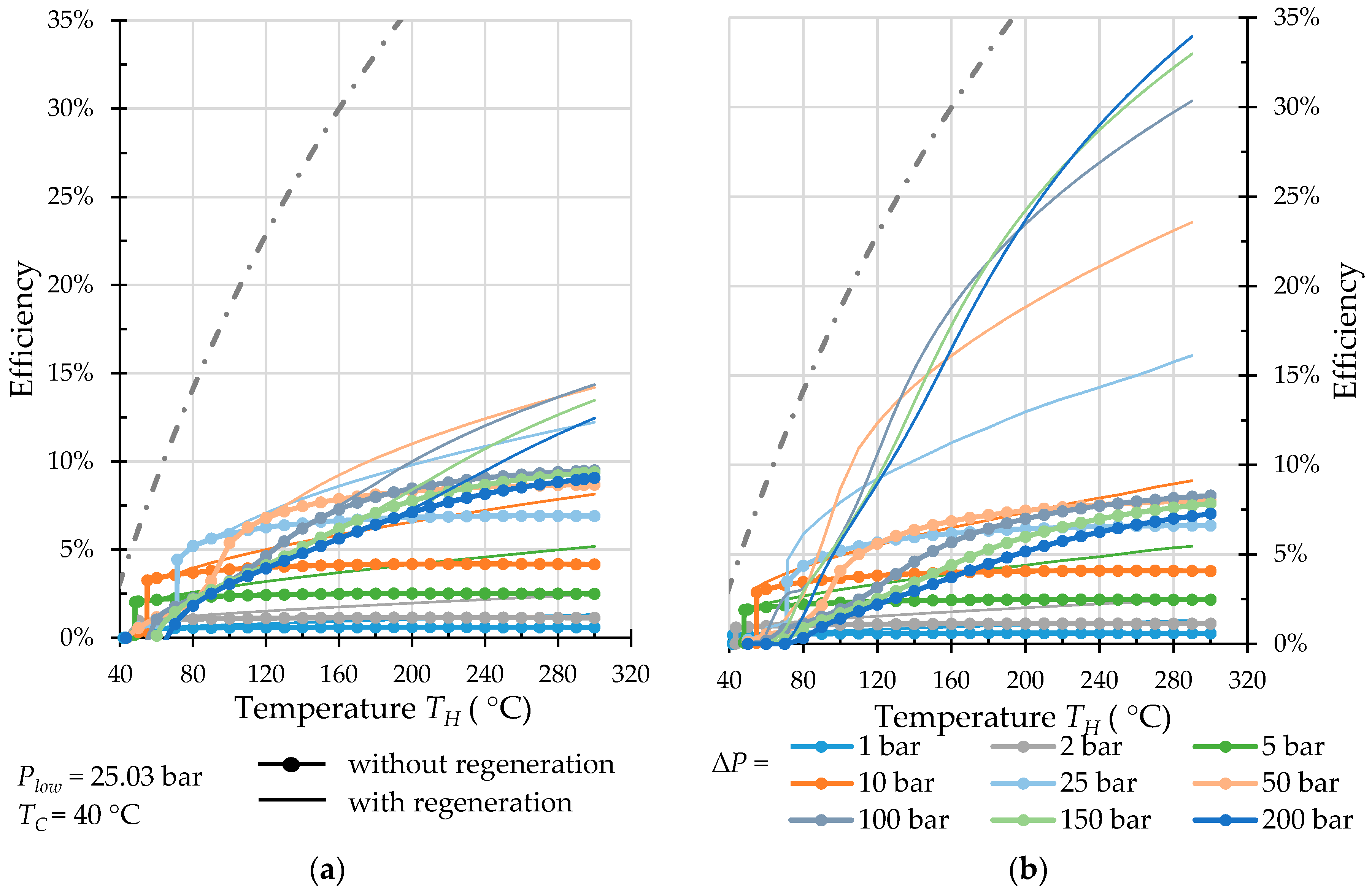
Figure 12.
Efficiency of regenerative Worthington-type machine (a) and Bush-type machine (b) operated with carbon dioxide.
Figure 12.
Efficiency of regenerative Worthington-type machine (a) and Bush-type machine (b) operated with carbon dioxide.

Figure 13.
Efficiency of regenerative Bush-type machine operated with carbon dioxide in high temperature range.
Figure 13.
Efficiency of regenerative Bush-type machine operated with carbon dioxide in high temperature range.

Figure 14.
Duplex Bush-type engine, consisting of two individual engines coupled by a common recuperative heat exchanger.
Figure 14.
Duplex Bush-type engine, consisting of two individual engines coupled by a common recuperative heat exchanger.
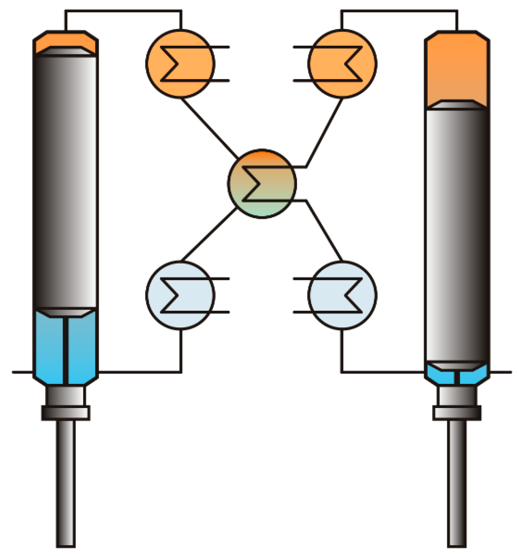
Figure 15.
Bush-type engine design for isothermal (a) and non-isothermal heat supply (b,c): 1—heater, 2—regenerator, 3—cooler, 4—regenerative heater.
Figure 15.
Bush-type engine design for isothermal (a) and non-isothermal heat supply (b,c): 1—heater, 2—regenerator, 3—cooler, 4—regenerative heater.

© 2018 by the authors. Licensee MDPI, Basel, Switzerland. This article is an open access article distributed under the terms and conditions of the Creative Commons Attribution (CC BY) license (http://creativecommons.org/licenses/by/4.0/).
Share and Cite
MDPI and ACS Style
Glushenkov, M.; Kronberg, A.; Knoke, T.; Kenig, E.Y. Isobaric Expansion Engines: New Opportunities in Energy Conversion for Heat Engines, Pumps and Compressors. Energies 2018, 11, 154. https://doi.org/10.3390/en11010154
AMA Style
Glushenkov M, Kronberg A, Knoke T, Kenig EY. Isobaric Expansion Engines: New Opportunities in Energy Conversion for Heat Engines, Pumps and Compressors. Energies. 2018; 11(1):154. https://doi.org/10.3390/en11010154
Chicago/Turabian StyleGlushenkov, Maxim, Alexander Kronberg, Torben Knoke, and Eugeny Y. Kenig. 2018. "Isobaric Expansion Engines: New Opportunities in Energy Conversion for Heat Engines, Pumps and Compressors" Energies 11, no. 1: 154. https://doi.org/10.3390/en11010154
Note that from the first issue of 2016, this journal uses article numbers instead of page numbers. See further details here.