1. Introduction
The paradigm change of power systems has created a need to modify traditional power systems for efficient energy supply [
1]. The use of high voltage direct current (HVDC) transmission systems allows for power transfer over longer distances with lower losses and improved power system controllability, and such systems are expected to become an essential technology in integrating renewable energy sources as transmission system backups [
2]. In particular, multi-terminal HVDC (MTDC) systems can simultaneously manage both active power and reactive power, and they provides a cost-effective solution for power system operation at each terminal independent of the direct current (DC) power transmission. In contrast to line-commutated converters (LCCs), a voltage source converter (VSC) is more suitable for establishing an MTDC system, because VSCs do not need reactive power demand and are able to control the reactive power to preserve the alternating current (AC) grid voltage as a generator [
3]. However, VSC-MTDC power transmission systems cannot be independently adjusted in the steady state owing to the limited active power capability of the VSC-HVDC, even though the output voltage magnitude and phase angle can be controlled. Therefore, a need exists for further research on power system operation to determine a suitable method for supplying additional active power to maintain the stability and reliability of the power system.
Various studies associated with optimal power flow (OPF) in renewable energy systems have been performed, such as those on VSC-HVDC and static synchronous compensator (STATCOM) [
4,
5,
6,
7,
8]. In [
4,
5,
6], an OPF-based control scheme was proposed to minimize the loss in an MTDC network for large offshore wind farms (WFs). A comprehensive OPF solution for a meshed AC/DC system with an MTDC network for offshore wind power transmission to minimize the transmission loss of the whole system with the grid code has been studied in [
7]. In [
8], a mixed AC/DC OPF model was developed for incorporating the VSC-MTDC system with a general configuration that can be used for operating and planning an AC transmission system with an embedded VSC-MTDC system. However, these studies only optimized the operation of the DC grid, and the AC system is not considered in the analysis. Therefore, conducting further studies related to WFs with VSC-MTDC systems need to be conducted by considering the entire power system, for an optimal operation of the AC/WF grids.
In addition, some recent works considered multi-objective optimization with renewable energy [
9,
10,
11]. A method has been proposed to optimize the planning of a bundled wind–thermal generation and transmission system taking into account the fuel cost, capital cost, maintenance cost, and loss based on the simulated annealing (SA) algorithm [
12]. However, these studies focused only on the transmission expansion planning for multi-objective optimization, and some of the researches still lack in the optimization approach for power system operation. In [
13], the authors presented a multi-objective model to find the solution of the optimal schedule of the units’ energy and reserves by integrating a thyristor-controlled series compensator (TCSC) device-based non-dominated sorting genetic algorithm II (NSGA-II) with the optimization problem developed under normal and contingency cases. In [
14], a design using a detached net zero-energy house located in Southern Italy to minimize thermal and visual discomfort using NSGA-II was presented. Though the NSGA-II algorithm encompasses several advanced concepts, including elitism, fast non-dominated sorting approach and diversity maintenance along the Pareto-optimal front, it still falls short in maintaining lateral diversity and obtaining the Pareto-front with high uniformity.
Energy-storage systems (ESS), which are capable of receiving energy, storing it for a period of time, and then returning it for use, can play an important role in power system control and significantly improve HVDC performance [
15]. An ESS can be used in an electrical grid to balance supply and demand. Compared to other technologies, the battery energy storage system (BESS) is the most cost-effective option coupled with power-electronic devices for an optimal operation of power systems. In recent times, various studies have been conducted on integrated systems for optimal operation [
16,
17,
18]. A control strategy including a hierarchical scheme has been developed for a multi-terminal HVDC network [
16]. In [
17], the demand response and ESS have been introduced to reduce the influence of wind power output uncertainty on the power system stability using the real-time outputs of thermal units and wind turbines and real-time charging/discharging behavior of energy storage. In [
18], the authors presented a new coordination control scheme between an offshore WF and a hydrogen management system for reducing the adverse impacts of wind variability. Even though, most of the studies discussed the advantages of coupling HVDC with ESS, they only focused on the control strategy. Hence, there is a need to investigate the compensation of active and reactive power together with the control scheme of an integrated power system. In particular, the benefits arising from the integration of VSC-HVDC with ESS include the independent control of active and reactive power, fast and reversible control of the power flow, and asynchronous decoupling of existing AC grids.
This paper proposes an economical optimization solution for multi-objective scheduling using the modified NSGA-II (MNSGA-II) in a hybrid network station (HNS) that is installed to regulate the active and reactive power control of meshed AC/WF grids. On using a VSC-MTDC system and the BESS, the HNS becomes capable of independent active and reactive power absorption from the grid and power injection into the grid. The integrated system focuses on the HNS operational capability and the BESS operational strategy for optimal multi-objective scheduling. We apply the optimization process based on the BESS charging/discharging strategy for the multi-objective scheduling while considering realistic demand profiles to arrive at the optimal solution. Moreover, decomposition-based optimization, which is applied as a part of the optimization formulations with the required HNS constraints to mitigate the violation for improving the overall computational efficiency, is also formulated in the proposed approach for meshed AC/WF grids. Using Benders’ decomposition (BD), the determination of the meshed AC.WF grid criteria is essentially decoupled from the multi-objective OPF, and these sub-problems can be solved independently. Therefore, the proposed scheduling solutions for multi-objective OPF are more feasible and economical, and the proposed Pareto solutions indicate the improved performance exhibiting faster convergence and divergence.
The rest of this paper is organized as follows in
Section 2, the modeling of the HNS for the meshed AC/WF grids is described, and the control and charging/discharging strategy based on the HNS are discussed. The optimization problem of the meshed AC/WF grids is formulated using parallel processing-based MNSGA-II, and the optimization process for optimal operation is summarized in
Section 3.
Section 4 presents and discusses the case study, and the conclusions are presented in
Section 5.
2. Hybrid AC/WF Network System
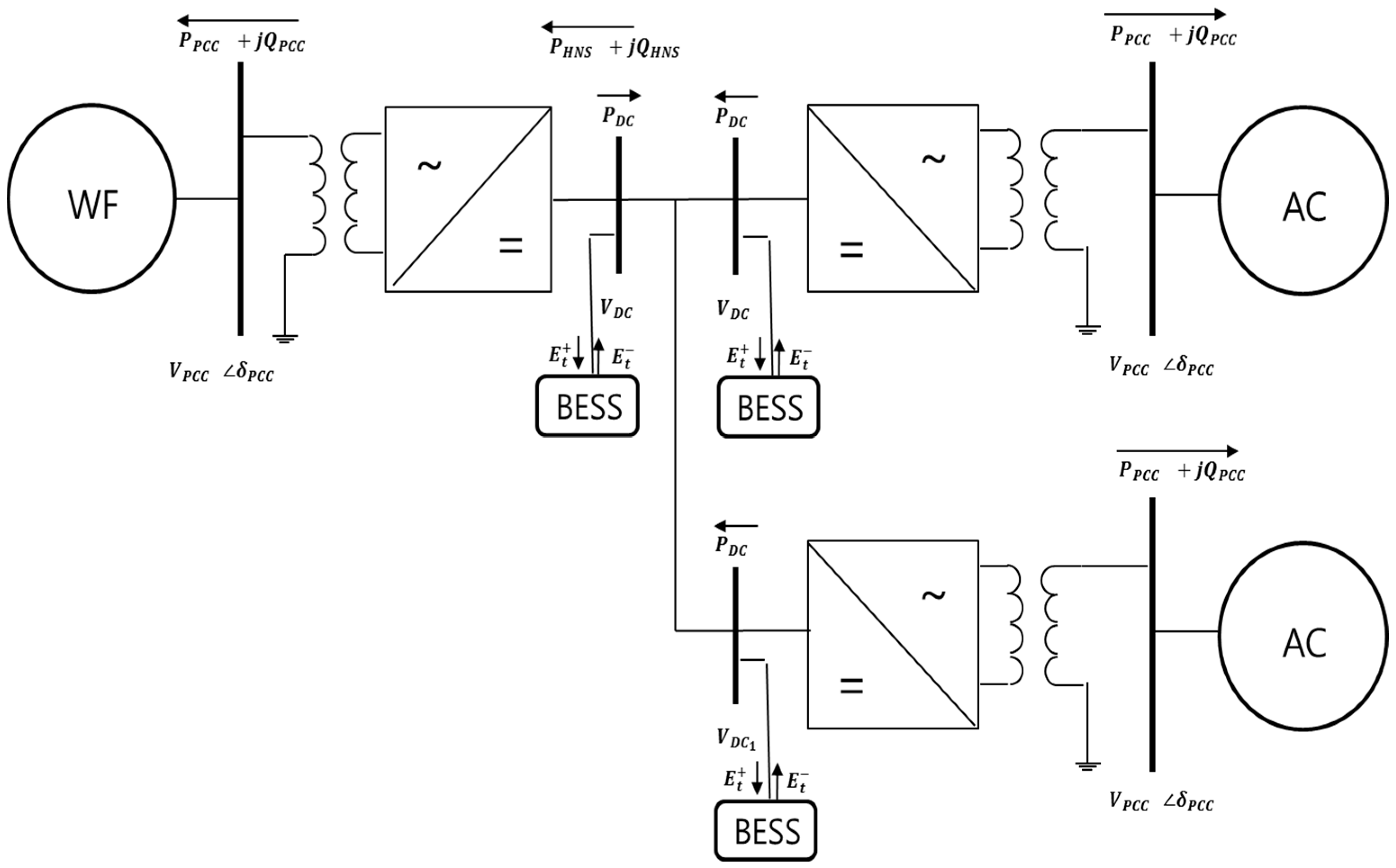
Figure 1 depicts the configuration of the hybrid network system that includes a VSC-MTDC and a BESS linking two different grids (i.e., AC and WF grids). More specifically, the system consists mainly of an AC bus, a coupling transformer, a BESS, a phase reactor, a converter block on the AC and DC sides, a DC bus, DC capacitors, and DC lines. In the system, power can only be transmitted in a unidirectional manner from the rectifier station to the inverter station. In general, the DC capacitor is not a bulk energy-storage device; the VSC-HVDC may not have the ability to provide active power compensation [
19]. Thus, this study is aimed at expanding the power regulation ability of the VSC-HVDC to enable both active and reactive power compensation by placing the BESS between the rectifier and inverter stations. Depending on the connected HVDC and BESS, the active/reactive power can be independently absorbed or injected from/to the grid. Consequently, the ability of the HNS to effectively provide extra active power enables the expansion of its compensating actions, thus, reducing transmission losses and improving power system operation of the meshed AC/WF grids.
2.1. Control of the AC/WF Grids
2.1.1. Onshore HNS Control
In an onshore HNS, the control strategy uses the voltage and power regulation mechanism. As shown in
Figure 1, the active and reactive powers introduced from the point of common coupling (PCC) bus to the converters in the active and reactive power control modes (PQ mode), are designated as
and
, respectively. In the PV mode, the magnitude of the voltage at the PCC bus is denoted as
. The converter connected to the DC slack bus regulates the DC voltage around a designated value and compensates the DC line losses. The BESS is also installed at
between the PCC bus and converter. The active power of all converters is identified through the PCC bus, with the exception of the slack converter. The active power of the slack converter can only be decided by the loss of the converter, DC line, and the other converter’s power flow.
2.1.2. Offshore HNS Control
The offshore HNS operates as a rectifier, and all of the AC energy delivered by the WF is transformed to DC and sent to land through the DC cables. However, the conversion must be conducted on an AC grid because this HNS control requires AC voltage to operate properly. To satisfy these requirements, this station is equipped with a control loop that adjusts the AC voltages on the PCC between the WF converter and the offshore HNS.
2.1.3. Wind Farm Converter Control
The WF converter takes the energy generated from the wind and supplies it to the offshore grid. The DC voltage control detects variations in the power owing to the charging and discharging of the DC capacitor. This outer control assigns a certain amount of current proportional to the wind power of the meshed AC/WF grid. Depending on the decouple control in the synchronous reference frame, reactive current can also be injected into the system [
20].
2.2. BESS Operational Strategy
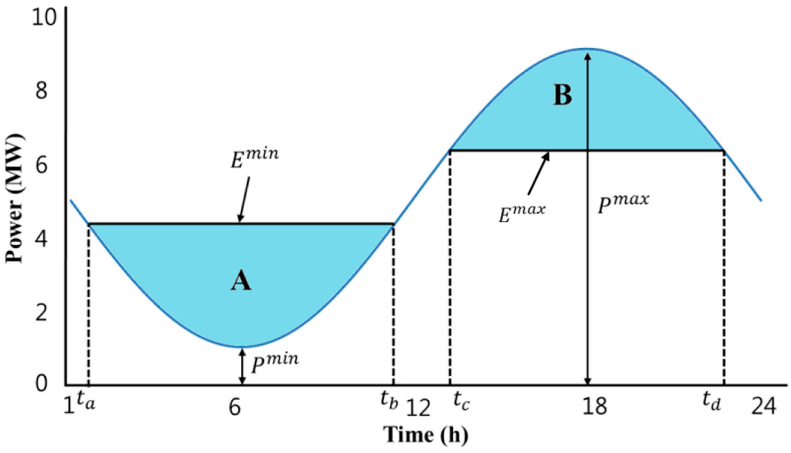
The BESS operational strategy can be explained with the help of
Figure 2. The battery strategy can be applied in real time, but the start and stop times should be planned based on the 24 h demand profile prediction.
The impact of the charging/discharging strategy is denoted by the shaded areas, which represent the energy. In the absence of the HNS, the feeder load is represented by a blue line. The feeder load increases as energy is transferred to the grids, which is indicated by the shaded area throughout the charging process. The charging process operates such that to minimize the cost of the energy purchased, Area A occupies a region as close as possible to when . Meanwhile, discharging takes place as close as possible to to maximize the price of the energy delivered when (Area B).


