
Alternative for Summer Use of Solar Air Heaters in Existing Buildings
by
 , ,
, ,
Sergio L. González-González
1 ,
,
Ana Tejero-González
1,*,
Francisco J. Rey-Martínez
1 and
Manuel Andrés-Chicote
2 1
Department of Energy Engineering and Fluidmechanics, University of Valladolid, 47002 Valladolid, Spain
2
CARTIF Technology Centre, Parque Tecnológico de Boecillo, 205, Boecillo, 47151 Valladolid, Spain
*
Author to whom correspondence should be addressed.
Energies 2017, 10(7), 985; https://doi.org/10.3390/en10070985
Submission received: 24 May 2017
/
Revised: 4 July 2017
/
Accepted: 5 July 2017
/
Published: 12 July 2017
(This article belongs to the Special Issue Solar Energy Application in Buildings)
Abstract
:Among solar thermal technologies for indoor heating, solar air heaters (SAH) are appealing for implementation on existing buildings due to their simplicity, fewer risks related to the working fluid, and possible independence from the building structure. However, existing research work mainly focuses on winter use and still fails in providing effective solutions for yearly operation, which would enhance their interest. With the aim of analysing an alternative summer use, this work firstly characterises a double channel-single pass solar air collector through experimentation. From the obtained results, modelling and simulation tasks have been conducted to evaluate the possibilities of using hot air, provided by the SAH, while operating under summer conditions within a closed loop, to feed an air-to-water heat exchanger for domestic hot water (DHW) production. The system is studied through simulation under two different configurations for a case study in Valladolid (Spain), during the period from May to September for different airflows in the closed loop. Results show that daily savings can vary from 27% to 85% among the different operating conditions; a configuration where make-up water is fed to the heat exchanger being preferable, with a dedicated water tank for the solar heated water storage of the minimum possible volume. The more favourable results for the harshest months highlight the interest of extending the use of the solar air heaters to the summer period.
1. Introduction
The harnessing of solar energy is living a slow development. Consequently, current work undertaken within the field encourages stronger promotion for the exploitation of this resource, particularly in sunny regions like the Mediterranean climate [1,2,3], where solar systems can be an efficient and economical alternative to fossil fuels [4].
Concerning solar thermal energy technologies, the use of air as the working fluid has some advantages: no risk of freezing in winter, no damage due to overheating in summer, no adverse effect of small leakage, corrosion is less critical, and the installation is simpler due to the unneeded additional heat exchanger for the final application [5,6]. The main disadvantages are, nonetheless, its lower density and lower thermal capacity, as well as its lower heat conductivity [7,8,9]. To overcome this, extensive work is being developed to enhance heat transfer, through different designs of the solar air collector [5,7] and roughness of the absorber in the form of obstacles of different shapes and sizes, like ribs and fins [7,10].
The advantages of the lower cost and wider possibilities of architectural integration have caused solar air heaters to spread in North America during the last 30 years. However, if compared to the total capacity of both air and water systems installed at a global scale by the end of 2014, of about 1.6 GWht, solar air heaters constitute just 0.4%. This percentage rises to 1.2% in Europe [11].
Solar air heating has a number of applications [7,12]. It has great potential for indirectly drying agricultural products, which, among the available methods, has demonstrated to be preferable for being quicker and of greater quality [13]. However, solar air heaters (SAH) are also extensively used for indoor thermal comfort. Hence, the above-mentioned advantages faced to water-based collectors make these systems of particular interest for applications in existing buildings.
Nevertheless, and despite the absence of the risk of damage due to overheating, the seasonality of SAH applications for indoor thermal comfort limits the interest in these systems [14]. To extend the use of SAH beyond the heating season, some strategies have been proposed in the literature.
The simplest alternative for SAH summer use is to still provide ventilation even though no heating demand exists, by simply shadowing the device during daytime, as proposed by Budea [1] and Ubertini and Desideri [2]. To the knowledge of the authors, the last case remained untested experimentally. The system would still operate efficiently during night-time [2,15] due to larger air volumes and long-wave night radiation.
Indeed, solar roof collectors, which belong to the same building envelope, are used during the summer season to enhance natural ventilation through the generated stack effect, of particular interest in hot and humid climates [14,16]. Extensive research work exists on different strategies to favour this [14,16,17,18].
Stack ventilation can be further improved by combining solar inducement with evaporative cooling. This alternative has been successfully implemented through different evaporative cooling devices in hot and dry climates [19,20], even if solar irradiation is low [3,21], but also in hot and humid climates [22,23,24].
Another alternative to extend the use of solar air collectors to the cooling season could be to use hot air for domestic hot water (DHW) production. This idea is proposed by Ito et al. [25], though they do not further develop it. Nonetheless, there exist solar collector prototypes that exploit solar radiation for heating either air or water flows. Ji et al. [9,26,27] developed a prototype designed to provide air heating during the winter season and water heating during the summer season. On the other hand, a prototype developed by Assari et al. [28] aimed at simultaneously providing both. Despite the first option being able to cleverly overcome the limitations of the seasonal use of SAHs without disregarding the need for a feasible integration in existing buildings [26,29], its actual integration appears to be rather complicated.
Within this context, the present work aims at extending the use of SAHs to a yearly operation by generating DHW during the summer season. Here, the interest of this alternative is evaluated through simulation for a case study. The model implemented in the simulation is based on the experimental results from a particular SAH.
2. Experimental Characterisation of the SAH
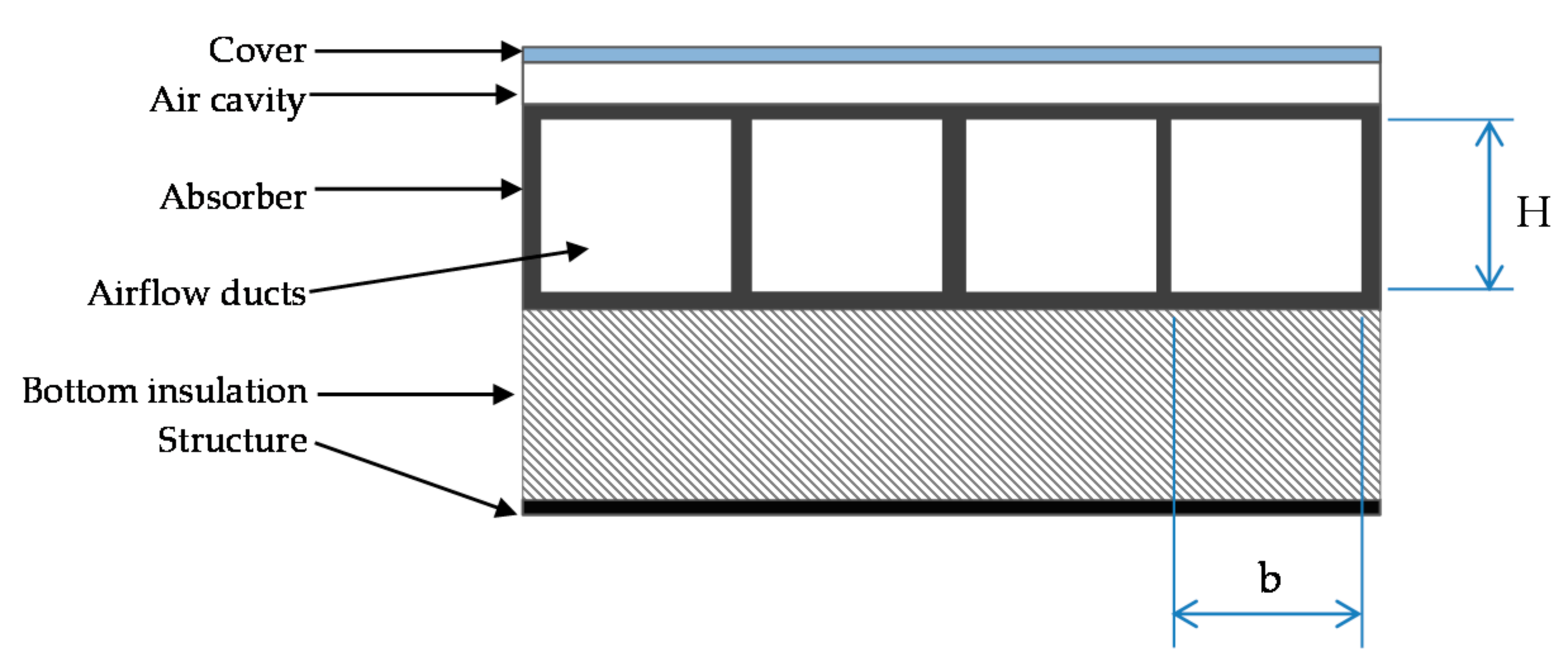
The SAH studied in this work is a double channel with a single cover, single pass back flow with rectangular slats dividing the air path into rectangular ducts. Back flow as the single pass in a double channel SAH has lower heat losses because of not being in contact with the cover, although radiant properties of the surfaces in the inside of the air path [30], as well as the D/L ratio [31], are determinants of the energy efficiency of the SAH [30]. Hence, better efficiencies can be expected in this case, despite the interest of double pass when front flow is performed [19,31]. Double flow also generates a greater pressure drop [32]. The rectangular slats can improve heat transfer from the absorber to the fluid.
2.1. Experimental Setup
Two collectors of the above-mentioned type, from the manufacturer Grammer Solar S.L. (Valencia, Spain), were connected in series. A schematic view of the cross-section and dimensions of the studied SAH are shown in Figure 1 and specified in Table 1.
Table 1 also gathers the radiative characteristics of the SAH. These properties correspond to generally-accepted values in the current literature and their use was validated for the simulation of the actual SAH in previous research developed by the authors [33].
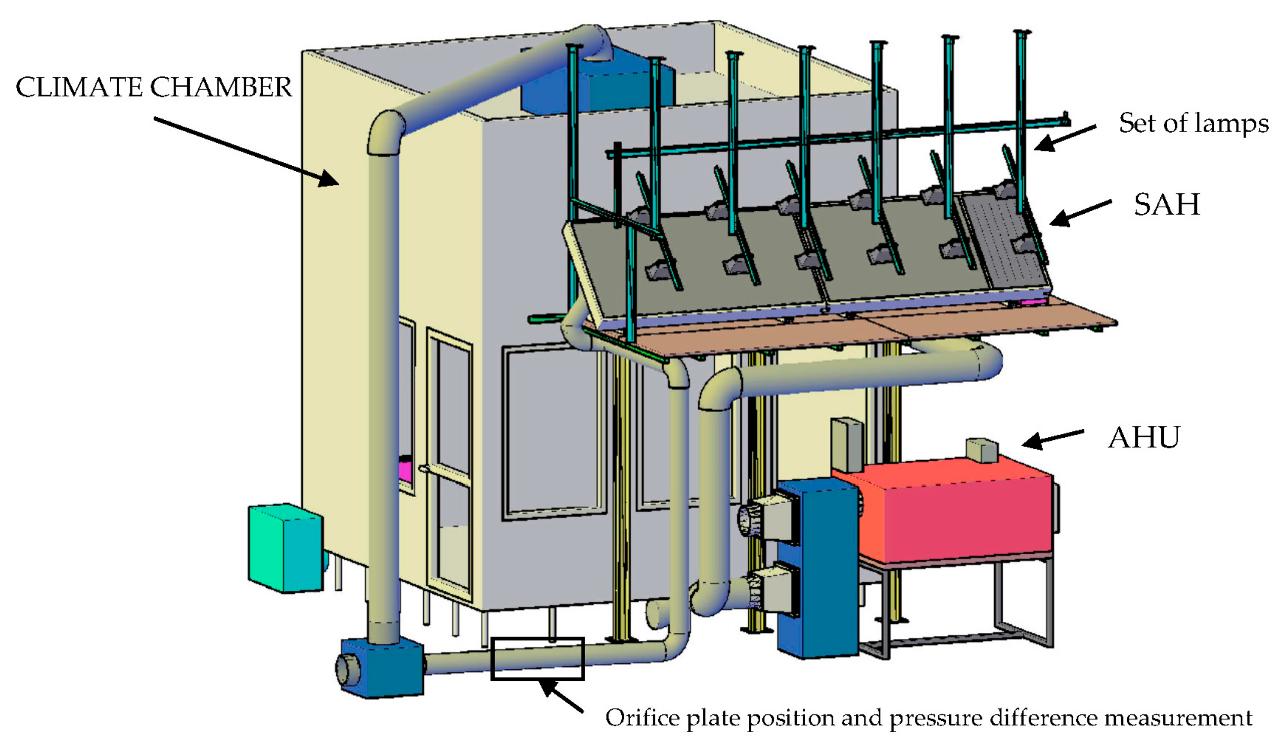
The SAHs were mounted on the experimental setup illustrated in Figure 2 and characterised taking into consideration the current standards [34]. Solar radiation is reproduced through a set of lamps, whereas outdoor air conditions are reproduced through an Air Handling Unit (AHU) equipped with the required filters and variable frequency drive fan system. Air heated in the SAH is then driven to a climate chamber. All elements are connected with flexible and PVC ducts of 20 cm diameter previously checked to avoid leaks.
Variables measured during the tests are: air dry bulb temperature and relative humidity at the SAH inlet and outlet, and airflow. The latter was measured downstream from the SAH according to current standards specifications for the characterisation of open-loop SAHs [34]. Temperature sensors are four-wire Pt100 probes with accuracy 0.1 °C and range from −50 °C to +250 °C, from the manufacturer RS. Relative humidity is measured with capacitive sensors (range 0 to 100% and accuracy ±2%) from Honeywell International Inc. Airflow is determined through the pressure drop registered in an orifice plate previously calibrated, with the aid of ultra-low differential pressure transmitters from Dwyer Instruments, INC., with a pressure range 0 mm to 703.1 mm H2O and an accuracy ±2%. RS (Pozuelo de Alarcón, Madrid, Spain) supplied all these sensors.
Lamps installed are halogen bulbs that provide 75% IR radiation, 5.75% visible radiation, and 0.25% ultraviolet; the remaining energy is dissipated through conduction and convection [35]. The setup consists of 12 lamps of 500 W each, placed uniformly in two rows at a distance of 0.5 m to the SAHs. Before developing the experimental tests, that irradiation achievable with all or alternate lamps being turned on is characterised by measurement with a pyranometer. It was placed on the surface of the two collectors connected in series and moved to different positions according to a rectangular grid. The measuring range covered by the pyranometer used, which corresponds to the model FLA628S from Ahlborn Equipment, Inc. (supplier: Electroson Castilla S.A., Valladolid, Spain), is 0 W/m2 to 1500 W/m2 and its accuracy is ±7%. Figure 3 shows the setup of the lamps and the measuring procedure.
The points of the grid and the levels of irradiation measured are shown in Figure 4 for both cases considered. Irradiation measured in node 12-B exceeded the range of the pyranometer and was considered with care.
The above results for the achievable irradiance enable the definition of two levels of irradiation in the tests performed, corresponding to average measured values of 828.4 W/m2 for all lamps and 447.9 W/m2 for half the lamps.
2.2. Results
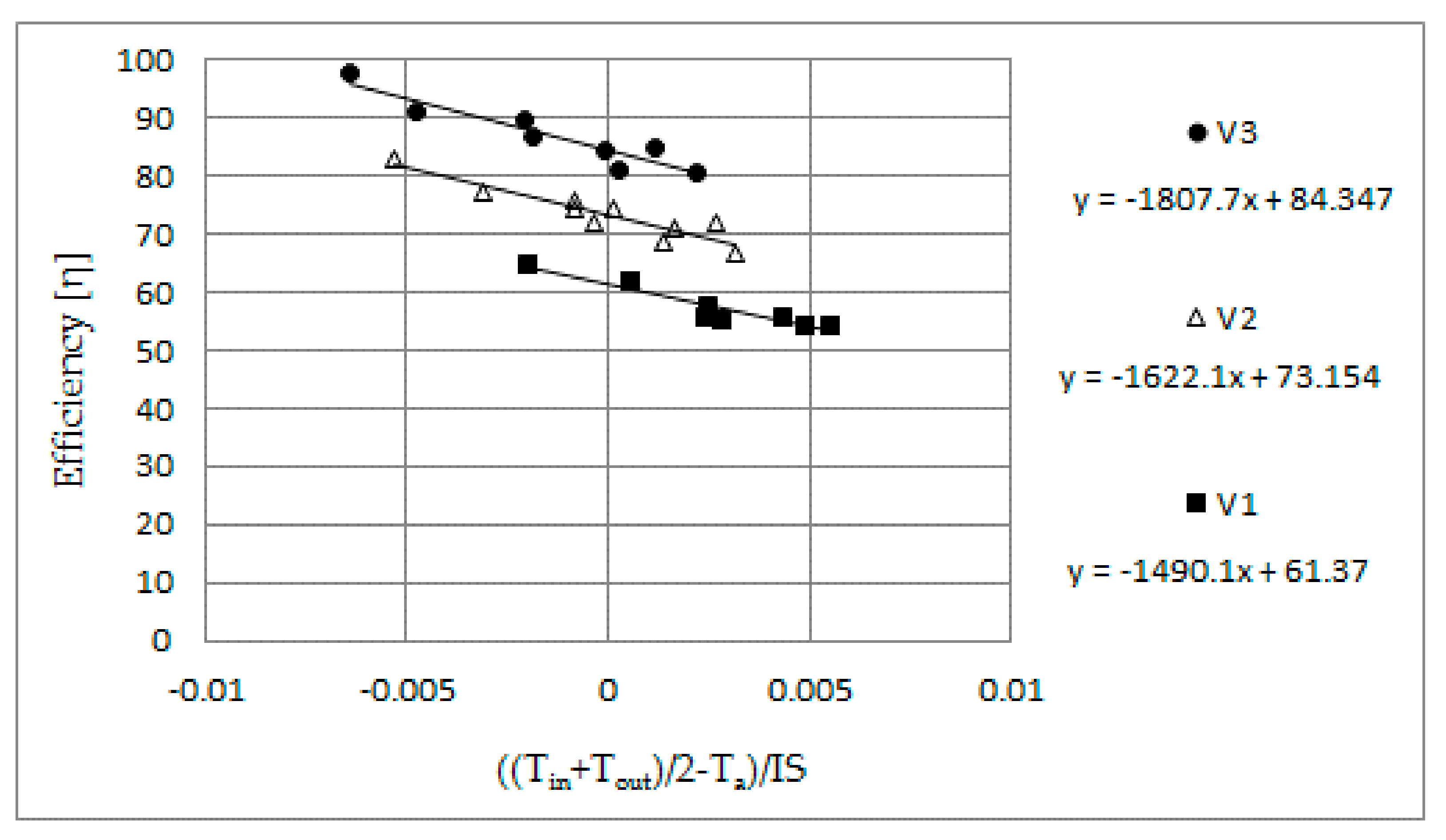
The developed design of experiments yielded three airflow levels (V1 = 100 m3/h, V2 = 200 m3/h and V3 = 300 m3/h) and four inlet air temperature levels (T1 = 0 °C, T2 = 5 °C, T3 = 10 °C, and T4 = 15 °C), which corresponds to the ambient air temperature (Ta) in the real operation of the system. Ambient temperature in the laboratory where the tests were performed was 21 °C. The experimental setup, described previously in Section 2.1, allowed two irradiance levels to be studied: 828.4 W/m2 and 447.9 W/m2. This resulted into 24 tests. Table 2 compiles the obtained experimental results. The efficiency versus the relation between ambient air temperature Ta and irradiation I (W/m2) is represented in Figure 5.
3. Simulation for DHW Generation
The SAH previously characterised through experimental testing is proposed here for summer application for DHW generation. With this purpose, heated air in the SAH could then be driven within a closed loop to heat water in a heat exchanger. The interest of this alternative is studied through simulation.
Water generated could be stored or consumed directly. Hence, three alternatives arise: instantaneous generation of DHW, water storage on a single tank equipped with the required auxiliary heating system, and water storage in a separated tank from the auxiliary generation system. Since instantaneous generation lacks interest due to non-simultaneous demand and generation, water storage is preferable. On the other hand, comparing both water storage alternatives, a single tank would be better in terms of space and investment. However, having a dedicated tank available separated from the auxiliary generation system would enable the solar system to operate independently of the required water storing set temperature (60 °C). Since better efficiencies can be expected, this last option is chosen.
Two configurations with two tanks are possible: (a) providing make-up water directly to the water tank or (b) mixing it with return water from the tank before delivering it to the heat exchanger (Figure 6). Results for both possibilities are obtained in order to determine which one is preferable. Additionally, the study compares three different capacities for the water tank.
The interest of the use of SAH for DHW generation is analysed based on the energy savings (in kWh/day) achievable during a typical day for each month from May to September, for a case study.
The defined case study considers the climate data of the city of Valladolid, Spain. Data required are the solar irradiation and ambient dry bulb temperature evolution. The expected tap water temperatures are also considered. This case study makes use of correlations of the evolution of these variables during typical days from TMY (typical meteorological year) data [36]. These correlations are gathered in Table 3.
The DHW demand corresponds to the expected one for a family of four members, set at 40 L per day and person, slightly over the levels established in the Spanish norm [37]. The total DHW demand is divided in three peaks between 8 a.m. and 9 a.m., 3 p.m. and 3:50 p.m., and 9 p.m. and 9:30 p.m.
3.1. Simulation Model
To model the behaviour of both configurations shown in Figure 6, each subsystem needs to be characterised. Here, the main criteria for the modelling of the heat exchanger, the first water tank (fed directly by the heat exchanger), and the SAH are presented.
Concerning the SAH, a device of the same total area as the one experimentally studied (4 m2) has been considered. Hence, results described in Section 2.2 yield the required information to predict its behaviour. The model is based on the energy balance defined in the SAH:
Equation (2) gives the outlet air temperature for each iteration:
The calculated air temperature at the outlet of the SAH is then the entering value for the heat exchanger. The considered heat exchanger is a finned coil whose well-known behaviour has been characterised through the method established by Kays and London [38]. The geometric characteristics of the heat exchanger surface are gathered in Table 4.
Finally, the modelling of the water tank enables the learning about the instantaneous water temperature available throughout the day and, thus, the prediction of the energy savings. No stratification has been considered for a supposed totally mixed tank. Heat losses have been calculated considering a transmittance of 1.5 W/K.
Iteration of the energy balance defined in the water tank (Equation (3)) yields the temperature of the stored water for an instant “I” (Equation (4)):
The three models have been implemented within two codes for the functions “SAH” and “COIL” in Excel. Calculation followed an iterative process as described in Figure 7.
3.2. Energy Savings
Energy savings are calculated from the difference between the total demand and the energy required from the auxiliary conventional system (Equation (5)). This relation depends on the available tap water temperature as well as on the temperature achieved in the water tank:
If the system succeeds to reach or exceed 60 °C in the tank, which is the set temperature for DHW, then the system does not need the auxiliary system to operate. In this case, less water flow than that demanded at a higher temperature would be supplied from the tank. This water flow can be calculated from Equation (6):
The energy savings being:
If water in the first tank does not reach the set temperature, then the auxiliary system will have to heat the water flow demanded from the first tank up to the set temperature achieved in the second tank:
The results of the thermal energy savings and the percentage of the total demand supplied are gathered in Table 5, Table 6 and Table 7.
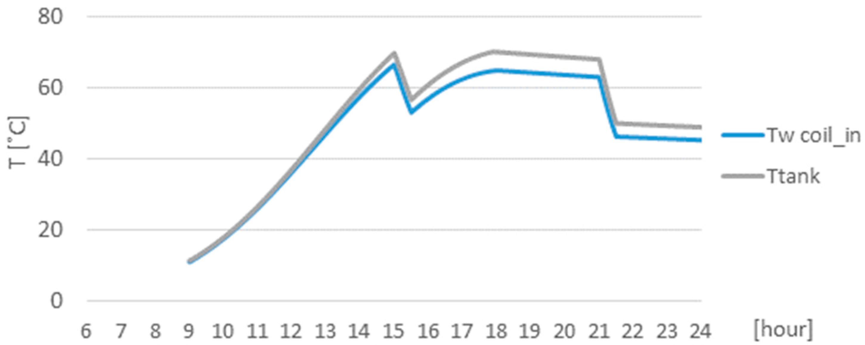
To observe in detail those temperatures achievable in the tank, the model has also implemented a code to show their evolution during each typical day for the different cases being proposed. As an example, for a 100 L tank, 100 m3/h airflow and configuration b during a typical day of August, Figure 8 shows the water temperature evolution both in the tank (supply) and at the coil inlet, once mixed with the reposition water (Tw coil in). Due to the decrease in the water tank temperature during the night and because when the first peak of demand occurs solar energy is not yet available, the remaining stored energy would be used (and the auxiliary heating system would be required to reach the DHW set temperature, foreseeably). Consequently, it can be seen that water temperature at 9:00 is close to that of tap water.
4. Discussion
Regarding the thermal efficiency curves obtained (Figure 5), the performance of the SAH improves under larger airflows. Despite the related fan power requirements, this result is a key point to heed. On the other hand, the smooth slopes denote a fair performance of the system in terms of heat losses whatever the operating conditions are (irradiation and ambient temperature).
For the highest level of irradiation performed (828.4 W/m2), average efficiencies are about 0.55, 0.72 and 0.85 for airflows of 100 m3/h, 200 m3/h, and 300 m3/h, respectively. When comparing these efficiencies to the ones of Ammari [6], performed on similar SAHs, similar results can also be observed: for an irradiation of about 850 W/m2 and 180 m3/h airflow, the average efficiency exceeds 0.7. Efficiencies obtained here are better than the ones achieved by Budea [1] from a similar system, which scarcely reach 45% for irradiations of about 850 W/m2, although no specific information on the operating airflows is given in this case. Due to this agreement, the present experimental results are considered representative of the operation of this sort of SAH in order to use the results in the model defined for the simulation.
However, obtained experimental efficiencies falling beyond 0.9 would not agree with the radiative properties of the SAH components considered in the model. Although validated in previous work, deviations of the experimental results from the model might be identified through further reproduction of the tests being performed.
By comparing the results of the simulation (Table 5, Table 6 and Table 7), clear trends can be observed for the studied conditions (airflow, tank volume, month, and configuration).
Concerning airflows in the SAH, greater flows improve energy savings due to the better performances of the system, previously discussed.
When studying the results obtained for the different summer months, energy savings improve for the harshest conditions, as could be expected. The increment observed in the energy savings for the harshest month—July—compared to the mildest—May (being this increment defined as the difference between the values of the energy savings for both months, then related to the lowest value)—is more noticeable for larger tank volumes, lower airflows, and for configuration b. For the smallest tank, highest flow, and configuration a, energy savings increase in about 21% from May to July; whereas for the largest tank, lowest flow, and configuration b, this relation reaches 41%. This fact, rather than remaining obvious, highlights the interest of broadening the use of the SAH as indoor heating demand decreases.
Focusing on the tank size, larger volumes result in lower energy savings. While energy savings can reach 85% of the total demand for the most favourable case considering a 100 L tank, it remains below 50% for all cases when the tank volume is 500 L. This is because it is easier for the system to reach larger temperatures in smaller tanks. Nonetheless, lower water temperatures in the tank would result in higher temperature differences between both sides of the heat exchanger and, thus, a better heat transfer. Despite these better performances expected for the system equipped with a larger tank, the fact of not being capable of achieving the water set temperature would limit the possibilities of supplying the DHW flow demanded at the required temperature. Consequently, optimisation of the system relies on the design of the minimum tank volume that could guarantee the water flow supply during the demand peaks throughout the day.
Results also make clear that the best option is configuration b, since for every case the energy savings are noticeably higher under this one. This fact relies on the same reasoning stated for the water tank volume: by supplying make-up water directly to the heat exchanger, greater temperature differences are possible in the heat exchanger and, thus, better performances, without directly affecting the water temperature in the tank.
Additionally, the graph in Figure 8 shows how the system exceeds the set temperature of 60 °C during most of the daytime period. Hence, it would succeed in this case to partly supply the required hot water during the two demand peaks of 15 p.m. and 21 p.m. Concerning the demand peak of 9 a.m., depending on the stored water from the previous day, the auxiliary system would have to partly supply the demand. In this sense, performing a simulation for the whole summer period would give a more precise idea of the energy savings achievable, resulting in an enhanced interest of the system. Further comparison in terms of costs and efficiency through a life cycle analysis would be interesting in order to compare the viability of their installation relative to that of conventional solar water heating systems.
5. Conclusions
Solar air heaters (SAHs) are particularly interesting for integration in existing buildings, due to their simplicity and the further advantages facing water systems in terms of lower risks concerning freezing, overheating, leakage, or corrosion. In addition to the immediate application for winter indoor heating, extending the use to the summer period is appealing to improve energy savings and economic viability. However, summer applications proposed in the existing literature are rare and insufficiently studied.
In this paper, a double channel SAH with a single cover, single pass back flow with rectangular slats dividing the air path into rectangular ducts has been experimentally characterised. The results have been used to model their behaviour within an alternative application for DHW generation. This alternative has been analysed under the case study of a four-member family DHW demand, with the system operating under the climate conditions of Valladolid (Spain) during typical days from May to September.
The main experimental results show that efficiency of the SAH improves under larger airflows, despite larger fan power requirements.
The smooth slopes denote a fair performance of the system in terms of heat losses for any irradiation and ambient temperature levels. The obtained average efficiencies agree with those presented in the existing literature.
Concerning the proposed summer application, the best configuration considers a dedicated tank to store the solar heated water, independent from the auxiliary heating system, where make-up tap water is mixed with the return from the tank before being driven to the coil.
The preferable tank volume is the minimum possible, in order to optimise energy savings without hindering the DHW demand requirements.
From the evolution of the water temperature in the tank, it can be observed how the system can succeed to support the hot water demand during the peaks considered.
Finally, the best results are observed during the harshest months: this enhances the interest to extend the use of SAHs to summer operation through this alternative.
Supplementary Materials
The following are available online at www.mdpi.com/1996-1073/10/7/985/s1, Excel file: “SAHforDHW”.
Acknowledgments
This work was supported and its publication funded by the Education Department of the Regional Government of Castile and Leon and ERDF through the research project: “Evaluación energética y medida del confort térmico en edificios universitarios hacia cero energía, combinando enfriamiento evaporativo indirecto (EI) y estructuras térmicamente activadas (TABS)” [ref.: VA029U16].
Author Contributions
Sergio L. González-González and Francisco J. Rey-Martínez conceived and designed the experiments. Sergio L. González-González performed the experiments. Manuel Andrés-Chicote developed the mathematical model and performed the simulation. Sergio L. González-González and Ana Tejero-González analyzed the data. Ana Tejero-González wrote the paper.
Conflicts of Interest
The authors declare no conflict of interest. The founding sponsors had no role in the design of the study; in the collection, analyses, or interpretation of data; in the writing of the manuscript, and in the decision to publish the results.
Nomenclature
| Mass flow (kg/s) | |
| b | Width of air ducts (mm) |
| cp | Specific heat (kJ/(kg×K)) |
| H | Height of air ducts (mm) |
| I | Irradiation (W/m2) |
| L | Length of air ducts (m) |
| M | Mass (kg) |
| S | Collector surface (m2) |
| T | Temperature (°C) |
| t | Time [s] |
| V | Air volume flow (m3/h) |
| η | Efficiency (⁰/1) |
| Subindexes | |
| a | Ambient |
| coil | Finned coil heat exchanger |
| In | Inlet flow |
| Out | Outlet flow |
| SAH | Solar air heater |
| tank | Water inside the tank |
| w | Water |
| demand | Demand of DHW |
References
- Budea, S. Solar air collectors for space heating and ventilation applications-performance and case studies under Romanian climatic conditions. Energies 2014, 7, 3781–3792. [Google Scholar] [CrossRef]
- Ubertini, S.; Desideri, U. Design of a solar collector for year-round climatization. Renew. Energy 2003, 28, 623–645. [Google Scholar] [CrossRef]
- Abdallah, A.S.; Yoshino, H.; Goto, T.; Enteria, N.; Radwan, M.M.; Eid, M. Integration of evaporative cooling technique with solar chimney to improve indoor thermal environment in the New Assiut City, Egypt. Int. J. Energy Environ. Eng. 2013, 4, 45. [Google Scholar] [CrossRef]
- Tsalikis, G.; Martinopoulos, G. Solar energy systems potential for nearly net zero energy residential buildings. Sol. Energy 2015, 115, 743–756. [Google Scholar] [CrossRef]
- Saxena, A.; Varun; El-Sebaii, A.A. A thermodynamic review of solar air heaters. Renew. Sustain. Energy Rev. 2015, 43, 863–890. [Google Scholar] [CrossRef]
- Ammari, H.D. A mathematical model of thermal performance of a solar air heater with slats. Renew. Energy 2003, 28, 1597–1615. [Google Scholar] [CrossRef]
- Oztop, H.F.; Bayrak, F.; Hepbasli, A. Energetic and exergetic aspects of solar air heating (solar collector) systems. Renew. Sustain. Energy Rev. 2013, 21, 59–83. [Google Scholar] [CrossRef]
- Alvarez, G.; Arce, J.; Lira, L.; Heras, M.R. Thermal performance of an air solar collector with an absorber plate made of recyclable aluminum cans. Sol. Energy 2004, 77, 107–113. [Google Scholar] [CrossRef]
- Ma, J.; Sun, W.; Ji, J.; Zhang, Y.; Zhang, A.; Fan, W. Experimental and theoretical study of the efficiency of a dual-function solar collector. Appl. Therm. Eng. 2011, 31, 1751–1756. [Google Scholar] [CrossRef]
- Gawande, V.B.; Dhoble, A.S.; Zodpe, D.B. Effect of roughness geometries on heat transfer enhancement in solar thermal systems—A review. Renew. Sustain. Energy Rev. 2014, 32, 347–378. [Google Scholar] [CrossRef]
- Mauthner, F.; Weiss, W.; Spörk-Dür, M. Solar Heat Worldwide. Markets and Contribution to the Energy Supply 2014; IEA Solar Heating & Cooling Programme: Gleisdorf, Austria, 2016. [Google Scholar]
- Kalogirou, S.A. Solar thermal collectors and applications. Prog. Energy Combust. Sci. 2004, 30, 231–295. [Google Scholar] [CrossRef]
- El-Sebaii, A.A.; Shalaby, S.M. Solar drying of agricultural products: A review. Renew. Sustain. Energy Rev. 2012, 16, 37–43. [Google Scholar] [CrossRef]
- Hirunlabh, J.; Wachirapuwadon, S.; Pratinthong, N.; Khedari, J. New configurations of a roof solar collector maximizing natural ventilation. Build. Environ. 2001, 36, 383–391. [Google Scholar] [CrossRef]
- Yoshie, R.; Satake, A.; Mochida, A.; Kato, S.; Yoshino, H. Energy conservation effect of new HVAC system for condominiums with solar collectors integrated with the balcony handrail. Energy Build. 2006, 38, 1360–1367. [Google Scholar] [CrossRef]
- Khedari, J.; Mansirisub, W.; Chaima, S.; Pratinthong, N.; Hirunlabh, J. Field measurements of performance of roof solar collector. Energy Build. 2000, 31, 171–178. [Google Scholar] [CrossRef]
- Yusoff, W.F.M.; Sapian, A.R.; Salleh, E.; Adam, N.M.; Hamzah, Z.; Mamat, M.H.H. Using computational fluid dynamics in the determination of solar collector orientation and stack height of a solar induced ventilation prototype. Sci. Technol. 2014, 22, 273–288. [Google Scholar]
- Yusoff, W.F.M.; Salleh, E.; Adam, N.M.; Sapian, A.R.; Yusof Sulaiman, M. Enhancement of stack ventilation in hot and humid climate using a combination of roof solar collector and vertical stack. Build. Environ. 2010, 45, 2296–2308. [Google Scholar] [CrossRef]
- Zhai, X.Q.; Dai, Y.J.; Wang, R.Z. Comparison of heating and natural ventilation in a solar house induced by two roof solar collectors. Appl. Therm. Eng. 2005, 25, 741–757. [Google Scholar] [CrossRef]
- Al Touma, A.; Ghali, K.; Ghaddar, N.; Ismail, N. Solar chimney integrated with passive evaporative cooler applied on glazing surfaces. Energy 2016, 115, 169–179. [Google Scholar] [CrossRef]
- Maerefat, M.; Haghighi, A.P. Natural cooling of stand-alone houses using solar chimney and evaporative cooling cavity. Renew. Energy 2010, 35, 2040–2052. [Google Scholar] [CrossRef]
- Chungloo, S.; Limmeechokchai, B. Utilization of cool ceiling with roof solar chimney in Thailand: The experimental and numerical analysis. Renew. Energy 2009, 34, 623–633. [Google Scholar] [CrossRef]
- Chungloo, S.; Limmeechokchai, B. Application of passive cooling systems in the hot and humid climate: The case study of solar chimney and wetted roof in Thailand. Build. Environ. 2007, 42, 3341–3351. [Google Scholar] [CrossRef]
- Miyazaki, T.; Akisawa, A.; Nikai, I. The cooling performance of a building integrated evaporative cooling system driven by solar energy. Energy Build. 2011, 43, 2211–2218. [Google Scholar] [CrossRef]
- Ito, S.; Kashima, M.; Miura, N. Flow Control and Unsteady-State Analysis on Thermal Performance of Solar Air Collectors. J. Sol. Energy Eng. 2006, 128, 354. [Google Scholar] [CrossRef]
- Jie, J.; Wang, W.; Sun, W.; Zhi, Y. Study of Space Heating by Dual-function solar collectors. Chin. Sci. Bull. 2014, 59, 1890–1895. [Google Scholar] [CrossRef]
- Ji, J.; Luo, C.; Chow, T.T.; Sun, W.; He, W. Thermal characteristics of a building-integrated dual-function solar collector in water heating mode with natural circulation. Energy 2011, 36, 566–574. [Google Scholar] [CrossRef]
- Assari, M.R.; Basirat Tabrizi, H.; Jafari, I. Experimental and theoretical investigation of dual purpose solar collector. Sol. Energy 2011, 85, 601–608. [Google Scholar] [CrossRef]
- Ji, J.; Luo, C.L.; Sun, W.; He, W.; Pei, G.; Han, C.W. A numerical and experimental study of a dual-function solar collector integrated with building in passive space heating mode. Chin. Sci. Bull. 2010, 55, 1568–1573. [Google Scholar] [CrossRef]
- Al-kamil, M.T. Effect of thermal radiation solar air heaters inside. Energy Convers. Manag. 1997, 38, 1451–1458. [Google Scholar] [CrossRef]
- Choudhury, C.; Chauhan, P.M.; Garg, H.P. Performance and cost analysis of two-pass solar air heaters. Heat Recover. Syst. CHP 1995, 15, 755–773. [Google Scholar] [CrossRef]
- El-Sebaii, A.A.; Al-Snani, H. Effect of selective coating on thermal performance of flat plate solar air heaters. Energy 2010, 35, 1820–1828. [Google Scholar] [CrossRef]
- González-González, S.L.; Sanza-Pérez, J.; Andrés-Chicote, M.; Tejero-González, A.; Rey-Martínez, F.J.; Velasco-Gómez, E. Modelado numérico de un colector solar de aire. In Proceedings of the 8th National Congress on Thermodynamic Engineering, Burgos, Spain, 19–21 June 2013. [Google Scholar]
- European Commitee for Standardization. Solar Energy—Solar Thermal Collectors—Test Methods; ISO 9806; European Committee for Standardization: Bruxelles, Belgium, 2013. [Google Scholar]
- Cuadernos de Eficacia Energética en Iluminación; Comite Espanol Iluminacion: Madrid, Spain, 1996.
- Spanish Standard; Spanish Building Code (Código Técnico de la Edificación); Ministerio de Fomento: Madrid, Spain, 2006.
- Spanish Standard: Regulations for Building Thermal Systems (Reglamento de Instalaciones Térmicas en Edificios); Ministerio de Industria, Turismo y Comercio & Ministerio de la Vivienda: Madrid, Spain, 2007.
- Kays, W.M.; London, A.L. Compact Heat Exchangers, 3rd ed.; McGraw-Hill: London, UK, 1984. [Google Scholar]
Figure 1.
Schematic cross-section of the SAH.

Figure 2.
3D view of the experimental setup.

Figure 3.
(a) View of the structure of the halogen lamps on the SAHs; and (b) the grid and pyranometer used for measuring irradiation.
Figure 3.
(a) View of the structure of the halogen lamps on the SAHs; and (b) the grid and pyranometer used for measuring irradiation.
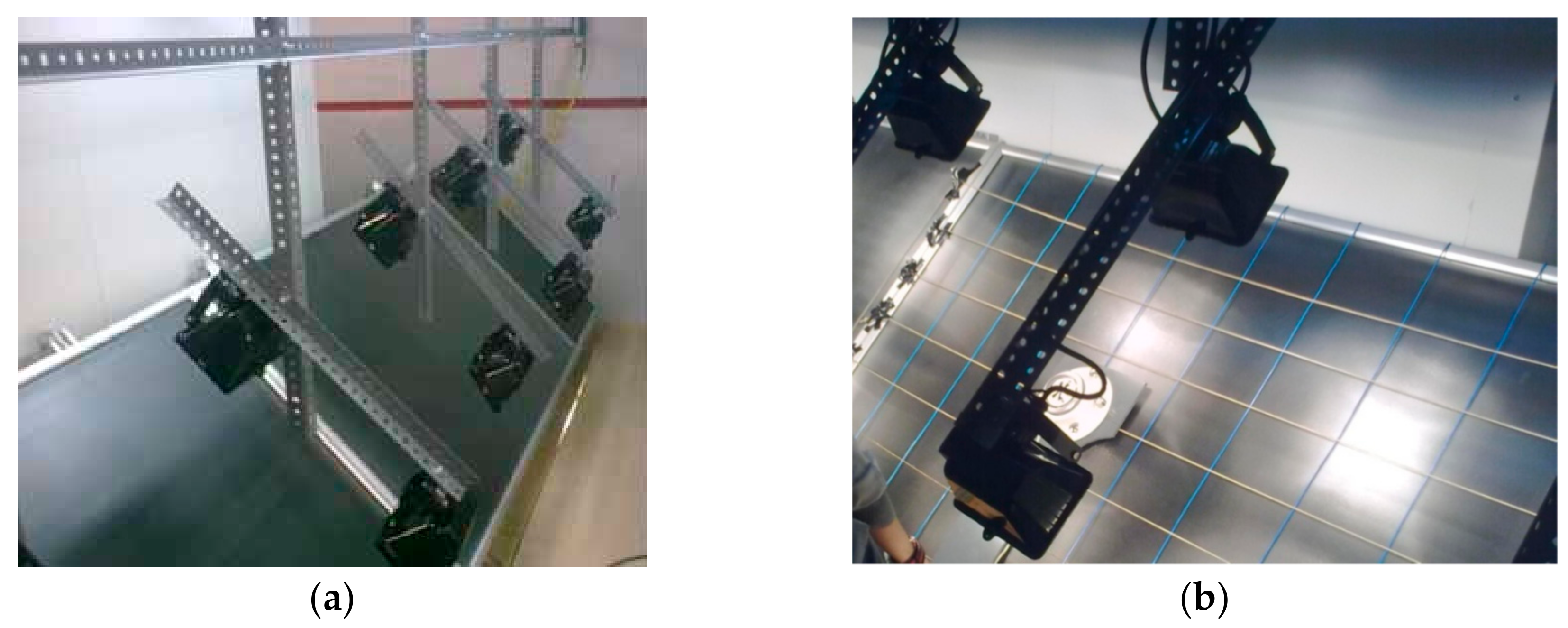
Figure 4.
Irradiation measured on the knots of the grid (a) with all lamps; and (b) with only alternate lamps.
Figure 4.
Irradiation measured on the knots of the grid (a) with all lamps; and (b) with only alternate lamps.
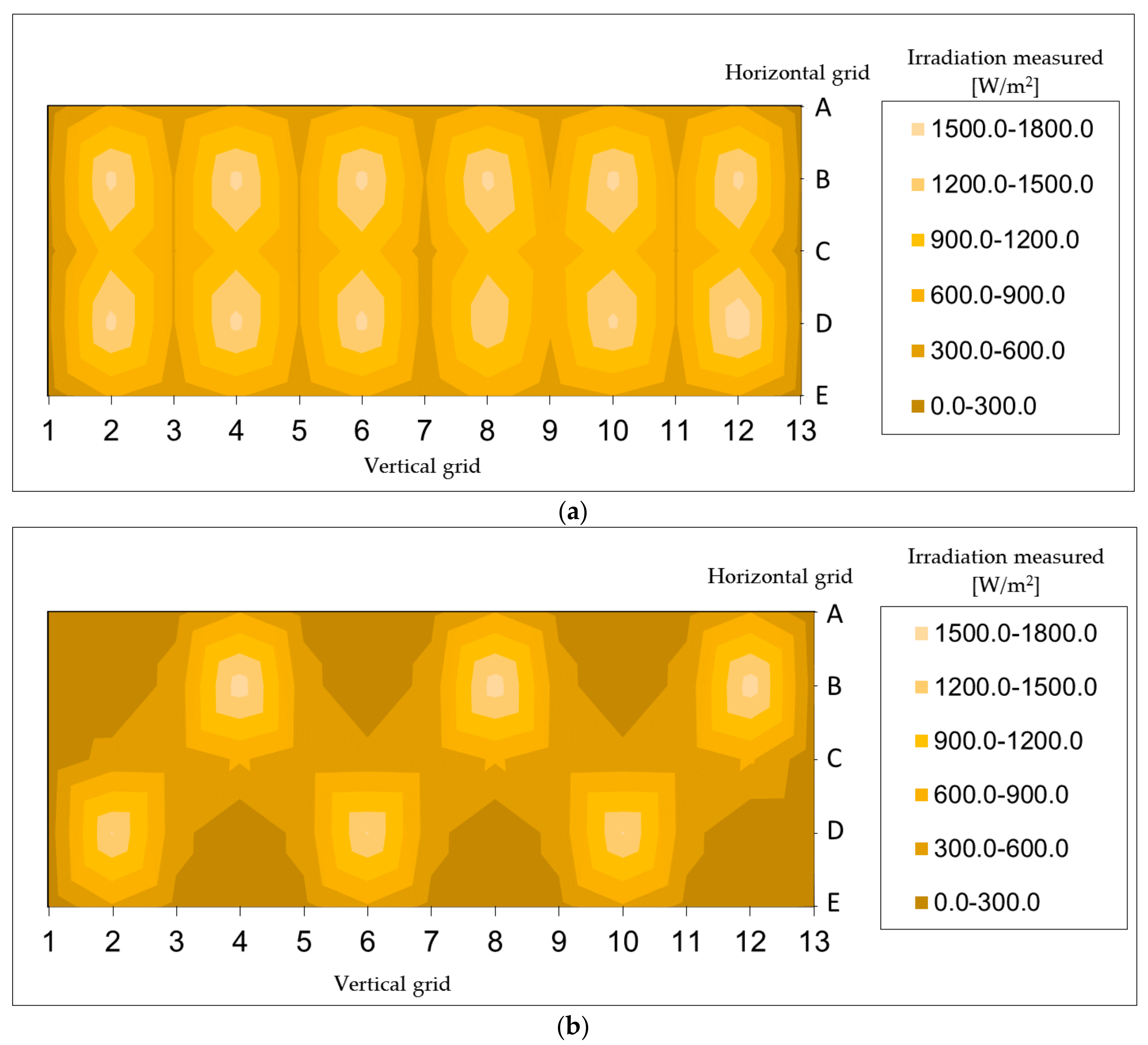
Figure 5.
Curves of efficiency for the different airflows studied.

Figure 6.
Possible configurations with two tanks: (a) water reposition to the tank; and (b) water reposition mixed with return water from the tank.
Figure 6.
Possible configurations with two tanks: (a) water reposition to the tank; and (b) water reposition mixed with return water from the tank.
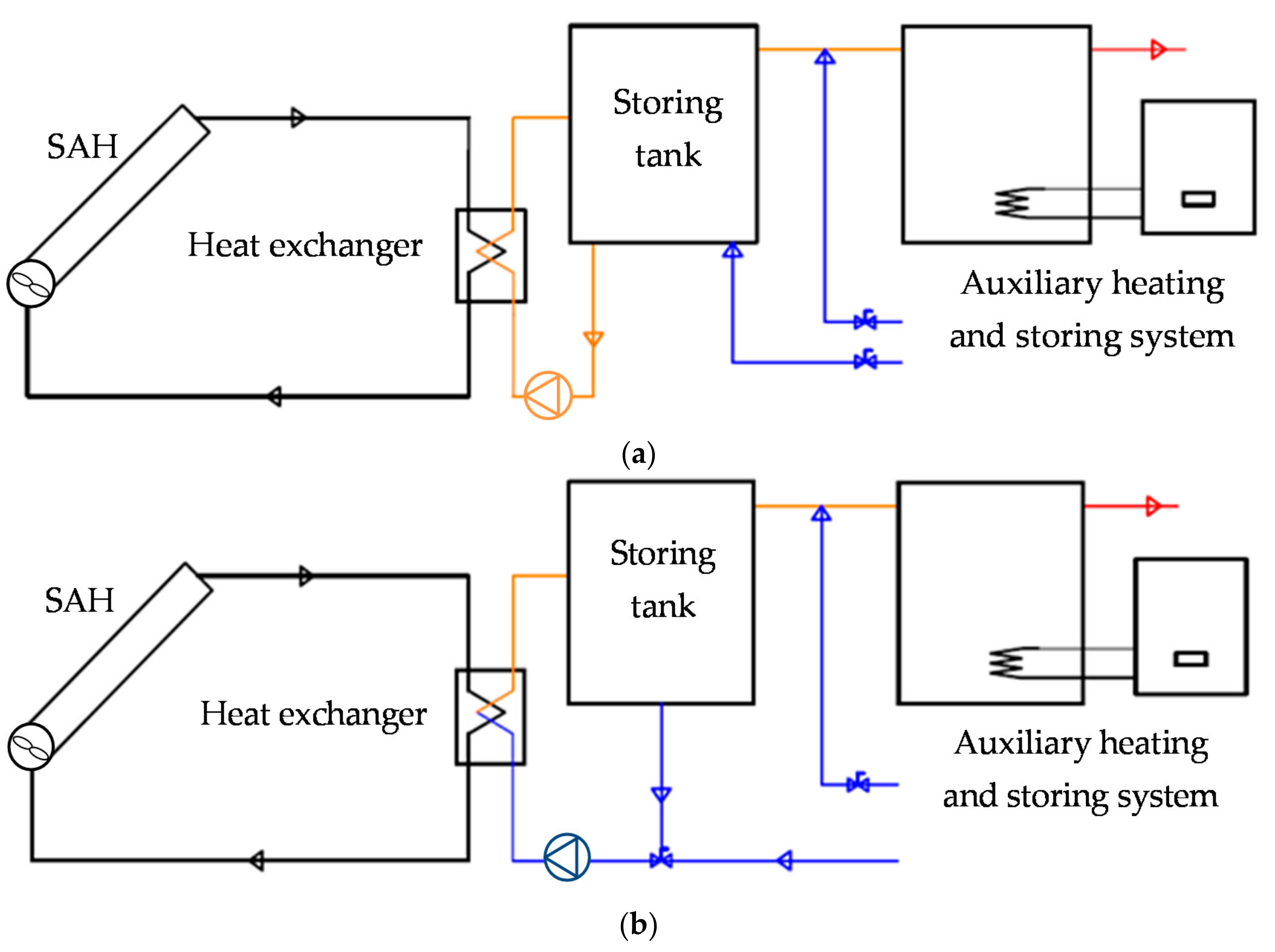
Figure 7.
Flowchart showing the computation methodology.
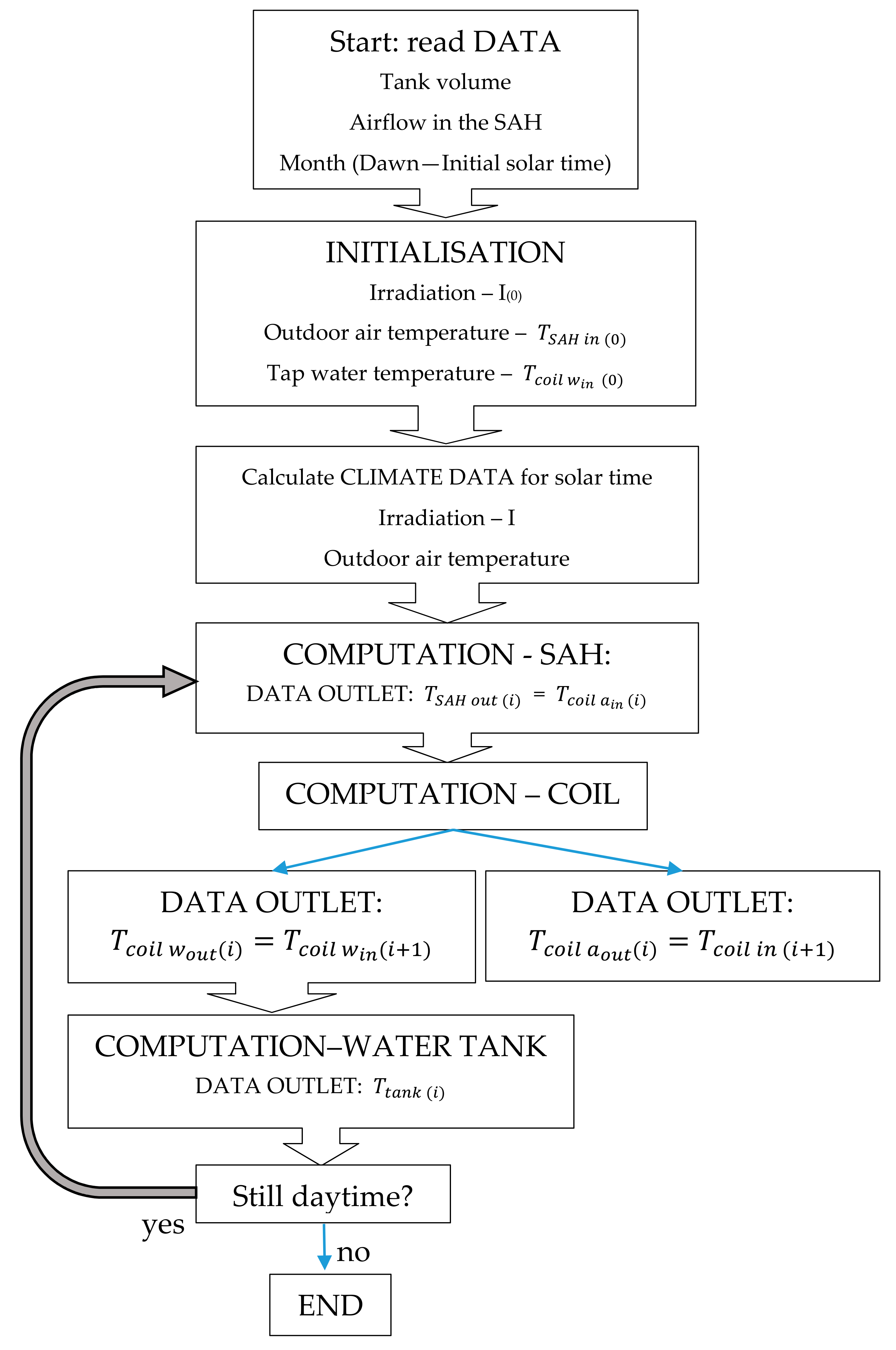
Figure 8.
Water temperatures evolution in the tank and at the inlet of the heat exchanger, for configuration b.
Figure 8.
Water temperatures evolution in the tank and at the inlet of the heat exchanger, for configuration b.


Table 1.
Characteristics of each SAH.
| Dimensions | |
|---|---|
| Cover thickness | 4 mm |
| Depth of air cavity between absorber and cover | 10 mm |
| Height of air ducts (H) | 34 mm |
| Width of air ducts (b) | 40 mm |
| Thickness of ducts | 3 mm |
| Thickness of bottom insulation | 50 mm |
| Number of ducts/paths | 24 |
| Length of ducts (1 collector) (L) | 2 m |
| Collector surface (S) | 2 m2 |
| Radiant Properties | |
| Long wavelength emissivity of the inside walls (absorber plate–bottom, base plate, ducts) | 0.1 |
| Short wavelength absorptivity of the absorber plate–top | 0.95 |
| Long wavelength absorptivity of the absorber plate–top | 0.11 |
| Short wavelength transmissivity of the cover | 0.9 |
| Short wavelength absorptivity of the cover | 0.08 |
| Long wavelength emissivity of the cover | 0.9 |
Table 2.
Experimental results of the SAHs.
| Average Air Temperatures | |||||
|---|---|---|---|---|---|
| Irradiation I (W/m2) | Average Airflow V (m3/h) | SAH Inlet T (°C) | SAH Outlet T (°C) | Temperature Difference ΔT (°C) | Efficiency η (⁰/1) |
| 828.4 | 111.6 | 15.1 | 63.6 | 48.5 | 0.544 |
| 828.4 | 111.3 | 10.4 | 60.1 | 49.6 | 0.556 |
| 828.4 | 110 | 5.6 | 55.2 | 49.7 | 0.55 |
| 828.4 | 96.2 | 0.2 | 57.7 | 57.5 | 0.556 |
| 447.9 | 101.8 | 15.4 | 44.2 | 28.7 | 0.544 |
| 447.9 | 100.7 | 10 | 40.8 | 30.6 | 0.577 |
| 447.9 | 100.9 | 5.5 | 38.5 | 33.1 | 0.621 |
| 447.9 | 102.3 | 0.3 | 34.4 | 34.1 | 0.649 |
| 828.4 | 201.3 | 14.9 | 47.9 | 33 | 0.668 |
| 828.4 | 217.9 | 13.4 | 46.2 | 32.9 | 0.72 |
| 828.4 | 214.3 | 10.2 | 43 | 32.6 | 0.707 |
| 828.4 | 213.7 | 4.1 | 38.6 | 34.5 | 0.742 |
| 828.4 | 202.9 | 2.2 | 37.4 | 35.2 | 0.718 |
| 828.4 | 205.1 | 0.2 | 36.3 | 36 | 0.744 |
| 447.9 | 214 | 14.9 | 32.1 | 17.3 | 0.687 |
| 447.9 | 210.7 | 9.9 | 29.2 | 19.3 | 0.755 |
| 447.9 | 207.3 | 5.5 | 25.4 | 19.9 | 0.769 |
| 447.9 | 204.6 | 0.6 | 22.3 | 21.8 | 0.829 |
| 828.4 | 322.8 | 15.9 | 40.7 | 24.6 | 0.806 |
| 828.4 | 305.4 | 11 | 38.6 | 27.6 | 0.849 |
| 828.4 | 310.1 | 7.2 | 34.2 | 27 | 0.843 |
| 828.4 | 330.8 | 0.7 | 27.6 | 26.9 | 0.895 |
| 447.9 | 298.9 | 14.2 | 28.8 | 14.5 | 0.809 |
| 447.9 | 320.6 | 10.3 | 24.9 | 14.6 | 0.869 |
| 447.9 | 328.4 | 5 | 19.9 | 14.9 | 0.91 |
| 447.9 | 332.4 | 1.7 | 17.5 | 15.8 | 0.976 |
Table 3.
Climatic data for Valladolid (typical days of summer months, from TMY data).
| Month | Correlation Coefficients—Dry Bulb Temperature (°C) | Tap Water T (°C) | |||||
| c0 | c1 | c2 | c3 | c4 | c5 | ||
| May | 20.82 | −3.713 | 5.945 × 10⁻¹ | −1.248 × 10⁻² | −1.004 × 10⁻³ | 3.143 × 10⁻⁵ | 11 |
| June | 22.33 | −3.813 | 6.460 × 10⁻¹ | −1.830 × 10⁻² | −7.543 × 10⁻⁴ | 2.774 × 10⁻⁵ | 12 |
| July | 23.87 | −3.763 | 6.022 × 10⁻¹ | −1.241 × 10⁻² | −1.044 × 10⁻³ | 3.258 × 10⁻⁵ | 13 |
| August | 24.72 | −3.404 | 3.983 × 10⁻¹ | 1.256 × 10⁻² | −2.189 × 10⁻³ | 5.058 × 10⁻⁵ | 12 |
| September | 23.46 | −2.945 | 2.213 × 10⁻¹ | 3.223 × 10⁻² | −3.055 × 10⁻³ | 6,407 × 10−5 | 11 |
| Month | Correlation Coefficients—Irradiation (W/m2) | Correction Factor | Dawn Time (h) | ||||
| d0 | d1 | d2 | d3 | d4 | (Slope = 42°) | ||
| May | 1038.5 | −815.94 | 161.55 | −10.629 | 0.22145 | 0.958 | 7 |
| June | 273.02 | −394.15 | 100.48 | −7.0051 | 0.14594 | 0.924 | 5 |
| July | 736.43 | −595.25 | 129.05 | −8.6873 | 0.18099 | 0.958 | 5 |
| August | 2417.5 | −1202.99 | 203.44 | −12.777 | 0.26618 | 1.068 | 6 |
| September | 1038.5 | −815.94 | 161.55 | −10.629 | 0.22145 | 1.236 | 7 |
Table 4.
Geometric characteristics of the heat exchanger surface.
| Dimensions | |
| Cross-sectional area (air) | 0.09 m2 |
| Cross-sectional area (water) | 0.0264 m2 |
| Total volume | 0.00792 m3 |
| Water Side | |
| Circular cross-section coil | |
| Total heat transfer area/Total volume | 45.695 m2/m3 |
| Outer diameter | 0.01 m |
| Inner diameter | 0.008 m |
| Total frontal area (one tube) | 5.5 × 10⁻⁴ m2 |
| Free-flow area (one tube) | 0.5026 × 10⁻⁴ m2 |
| Periferia interior de un tubo | 0.02513 m |
| Free-flow/frontal area | 0.091 |
| Air Side | |
| Hydraulic diameter | 0.9075 × 10⁻³ m |
| Total heat transfer area/Total volume | 587 m2/m3 |
| Fin area/total area | 0.913 |
| Fin thickness | 0.00033 m |
| Fin conductivity (Al) | 235 W/m∙k |
| Fin length (average distance between tubes) | 0.012 m |
| Free-flow/frontal area | 0.534 |
Table 5.
Energy savings achievable during typical summer days through both configurations for a water tank of 100 L.
Table 5.
Energy savings achievable during typical summer days through both configurations for a water tank of 100 L.
| Tank Volume: 100 L | Air Flow (m3/h): 100 | Air Flow (m3/h): 200 | Air Flow (m3/h): 300 | ||||
|---|---|---|---|---|---|---|---|
| Energy Savings: | Config. a | Config. b | Config. a | Config. b | Config. a | Config. b | |
| May | (kWh/day) | 5.22 | 5.64 | 5.81 | 6.23 | 5.90 | 6.30 |
| (%) | 57.4% | 62.0% | 64% | 68% | 65% | 69% | |
| June | (kWh/day) | 6.73 | 7.12 | 7.13 | 7.51 | 7.10 | 7.45 |
| (%) | 75% | 80% | 80% | 84% | 80% | 84% | |
| July | (kWh/day) | 6.98 | 7.29 | 7.44 | 7.69 | 7.43 | 7.64 |
| (%) | 77% | 80% | 82% | 85% | 82% | 84% | |
| August | (kWh/day) | 5.94 | 6.38 | 6.45 | 6.83 | 6.49 | 6.84 |
| (%) | 67% | 72% | 72% | 77% | 73% | 77% | |
| September | (kWh/day) | 6.37 | 6.74 | 6.80 | 7.16 | 6.82 | 7.15 |
| (%) | 73% | 77% | 78% | 6.23 | 78% | 82% | |
Table 6.
Energy savings achievable during typical summer days through both configurations for a water tank of 300 L.
Table 6.
Energy savings achievable during typical summer days through both configurations for a water tank of 300 L.
| Tank Volume: 300 L | Air Flow (m3/h): 100 | Air Flow (m3/h): 200 | Air Flow (m3/h): 300 | ||||
|---|---|---|---|---|---|---|---|
| Energy Savings: | Config. a | Config. b | Config. a | Config. b | Config. a | Config. b | |
| May | (kWh/day) | 3.48 | 3.62 | 4.01 | 4.17 | 4.31 | 4.49 |
| (%) | 38% | 40% | 44% | 46% | 47% | 49% | |
| June | (kWh/day) | 4.72 | 4.94 | 5.39 | 5.63 | 5.73 | 5.99 |
| (%) | 53% | 55% | 60% | 63% | 64% | 67% | |
| July | (kWh/day) | 4.81 | 5.15 | 5.47 | 5.85 | 5.82 | 6.22 |
| (%) | 53% | 57% | 60% | 64% | 64% | 68% | |
| August | (kWh/day) | 3.98 | 4.17 | 4.58 | 4.79 | 4.92 | 5.13 |
| (%) | 45% | 47% | 51% | 54% | 55% | 58% | |
| September | (kWh/day) | 4.26 | 4.44 | 4.89 | 5.10 | 5.24 | 5.46 |
| (%) | 49% | 51% | 56% | 58% | 60% | 63% | |
Table 7.
Energy savings achievable during typical summer days through both configurations for a water tank of 500 L.
Table 7.
Energy savings achievable during typical summer days through both configurations for a water tank of 500 L.
| Tank Volume: 500 L | Air Flow (m3/h): 100 | Air Flow (m3/h): 200 | Air Flow (m3/h): 300 | ||||
|---|---|---|---|---|---|---|---|
| Energy Savings: | Config. a | Config. b | Config. a | Config. b | Config. a | Config. b | |
| May | (kWh/day) | 2.45 | 2.54 | 2.84 | 2.94 | 3.11 | 3.21 |
| (%) | 27% | 28% | 31% | 32% | 34% | 35% | |
| June | (kWh/day) | 3.30 | 3.42 | 3.80 | 3.94 | 4.12 | 4.26 |
| (%) | 37% | 38% | 43% | 44% | 46% | 48% | |
| July | (kWh/day) | 3.41 | 3.62 | 3.90 | 4.15 | 4.22 | 4.48 |
| (%) | 37% | 40% | 43% | 46% | 46% | 49% | |
| August | (kWh/day) | 2.81 | 2.94 | 3.26 | 3.41 | 3.53 | 3.66 |
| (%) | 32% | 33% | 37% | 38% | 40% | 41% | |
| September | (kWh/day) | 2.89 | 3.00 | 3.36 | 3.48 | 3.67 | 3.80 |
| (%) | 33% | 34% | 38% | 40% | 42% | 43% | |
© 2017 by the authors. Licensee MDPI, Basel, Switzerland. This article is an open access article distributed under the terms and conditions of the Creative Commons Attribution (CC BY) license (http://creativecommons.org/licenses/by/4.0/).
Share and Cite
MDPI and ACS Style
González-González, S.L.; Tejero-González, A.; Rey-Martínez, F.J.; Andrés-Chicote, M. Alternative for Summer Use of Solar Air Heaters in Existing Buildings. Energies 2017, 10, 985. https://doi.org/10.3390/en10070985
AMA Style
González-González SL, Tejero-González A, Rey-Martínez FJ, Andrés-Chicote M. Alternative for Summer Use of Solar Air Heaters in Existing Buildings. Energies. 2017; 10(7):985. https://doi.org/10.3390/en10070985
Chicago/Turabian StyleGonzález-González, Sergio L., Ana Tejero-González, Francisco J. Rey-Martínez, and Manuel Andrés-Chicote. 2017. "Alternative for Summer Use of Solar Air Heaters in Existing Buildings" Energies 10, no. 7: 985. https://doi.org/10.3390/en10070985
Note that from the first issue of 2016, this journal uses article numbers instead of page numbers. See further details here.