Article

Autonomous Wireless Self-Charging for Multi-Rotor Unmanned Aerial Vehicles

1
Faculty of Science, Engineering and Computing, Kingston University London, London SW15 3DW, UK
2
Visiting Associate Professor, Robotics Institute, Khalifa University of Science and Technology, P.O. Box 127788, Abu Dhabi 999041, UAE
3
Robotics Institute, Khalifa University of Science and Technology, P.O. Box 127788, Abu Dhabi 999041, UAE
*
Author to whom correspondence should be addressed.
Energies 2017, 10(6), 803; https://doi.org/10.3390/en10060803
Submission received: 25 April 2017 / Revised: 31 May 2017 / Accepted: 6 June 2017 / Published: 13 June 2017
(This article belongs to the Special Issue Wireless Power Transfer)

Abstract

:
Rotary-wing unmanned aerial vehicles (UAVs) have the ability to operate in confined spaces and to hover over point of interest, but they have limited flight time and endurance. Conventional contact-based charging system for UAVs has been used, but it requires high landing accuracy for proper docking. Instead of the conventional system, autonomous wireless battery charging system for UAVs in outdoor conditions is proposed in this paper. UAVs can be wirelessly charged using the proposed charging system, regardless of yaw angle between UAVs and wireless charging pad, which can further reduce their control complexity for autonomous landing. The increased overall mission time eventually relaxes the limitations on payload and flight time. In this paper, a cost effective automatic recharging solution for UAVs in outdoor environments is proposed using wireless power transfer (WPT). This research proposes a global positioning system (GPS) and vision-based closed-loop target detection and a tracking system for precise landing of quadcopters in outdoor environments. The system uses the onboard camera to detect the shape, color and position of the defined target in image frame. Based on the offset of the target from the center of the image frame, control commands are generated to track and maintain the center position. Commercially available AR.Drone. was used to demonstrate the proposed concept which is equppied with bottom camera and GPS. Experiments and analyses showed good performance, and about 75% average WPT efficiency was achieved in this research.

1. Introduction

Over the last few years, unmanned aerial vehicles (UAVs), particularly rotary-wing drones, have been used in many different applications in industry and military for surveillance, maintenance, transportation, delivery, and search and rescue tasks [1,2]. A quadcopter is a rotorcraft that is lifted and propelled by four rotors possesing high mobility and kinesis. Propellers mounted on high speed brushless DC motors provide the lift, electronic sensors and control system contribute towards the stable flight of the quadcopter. Due to their agile manoeuvrability, hovering and Vertical Take-Off and Landing (VTOL) capabilities, quadcopters are able to fly indoors as well as outdoors.
However, the depletion of onboard power source is the most significant limitation in persistent missions of any aerial vehicle. High current consumption by the motors requiring high capacity batteries, which are often heavy, prohibits long-time operations resulting in reduced flight time of the UAV. Quadcopter flight is limited to only few minutes, even with a fully charged battery. Any other payload will further reduce the flight time. Therefore, there is the obvious need to charge the quadcopter’s battery often for a long-time operation [3]. Normally, recharging process involves direct human intervention which motivates a design of autonomous recharging system resulting in uninterrupted flight operation.
Researcher have been exploring the concept of autonomous recharging for UAVs to increase the endurance and overall flight time [3,4,5]. In [6], researchers demonstrated the autonomous recharging on a charging dock for a ground robot and resuming its original task [6]. In [7], battery swapping station was implemented for small co-axial helicopters. iRobot’s (Bedford, Mass., USA) commercially available floor cleaning robot, “Roomba”, exhibited autonomous recharging capability by navigating to a charging dock [8] when low on power. However, a mainstream application for UAVs has still not been successfully deployed. In [4,5,9], reserchers have worked towards persistent missions with autonomous recharging stations for UAVs using contact-based charging stations. In addition, researchers relied on the precise position feedback system [10] in order to perform autonomous landing on the charging stations, which is not possible to use in outdoor environments. One major drawback of contact-based charging is the requirement of precise landing on the charging station and the mechanical system in order to strongly bond the electrodes for the conductivity, which eventually increases the control complexity and cost. Furthermore, it requires mm accuracy positioning, which is a challenge due to the unavailability of precise localization system in outdoor environments [11].
Global positioning system (GPS) receivers are mostly used for navigation of UAVs in outdoor environments. A stand-alone GPS receiver, however, cannot provide precise position feedback required for landing sequences of small UAVs. Thus, it limits the precise landing on the target, even if it has the coordinate of the site in the earth frame. Differential GPS (DGPS) can provide accurate position compared to conventional GPS but the weight of the recevier limits its use for miniature UAVs and is also not cost effective. Vision sensors serve as eyes of unmanned vehicles assigned for reconnaissance missions. Cameras are able to support the vehicle autonomy using visual information. In [12], simulation of the landing logic for a quadrotor UAV is provided. In [13,14], a full landing sequence of the quadrotor UAV is introduced in indoor environments. The authors used a visual marker for the moving landing site. Landing control of the quadrotor UAV outdoors, however, is difficult due to the absence of the precise position and velocity measurements from the external motion capture system. Instead, wind and gust disturb the landing sequence of the quadrotor.
At present, wireless power transfer (WPT) is popular among charging applications for smartphones and other electronic devices [15,16]. The strongly coupled magnetic resonant induction for WPT allows efficient and high power transmission to the distances up to 2 m [15]. Magnetic resonant induction-based WPT has little interference and disturbance with its environment, and its omni-directional characteristic motivated for the application to UAVs [16]. In addition, the concept of WPT has been used where UAVs power sensor networks wirelessly [17]. A similar concept of using inductive wireless charging was applied for recharging of drones in [18]. However, an external mobile robot was used to detect, track and approach the drone once it lands for charging, using a robotic arm equipped with inductive charging pads. All of the works mentioned in the above studies successfully demonstrated the application of WPT in various applications which motivated the current proposition of using WPT technology in enhancing the persistency of the UAVs for longer flight times in outdoor environments. This paper proposes a novel approach for longer flight of UAVs by integrating WPT techonology to automatic recharging. The WPT allows a certain degree of freedom in horizontal positioning, while still maintaining the coupling of resonant coils to transfer the power [3]. The omnidirectional nature of WPT allows the UAV to land without adjusting its heading. By incorporating multiple charging coils, the wireless power transmission surface area can be increased, which will further reduce the need of precise positioning [19]. The WPT system provides safe powering for charging devices that need to remain sterile or hermetically sealed (waterproof), which is an important factor to be considered in outdoor environments. Furthermore, it prevents corrosion and eliminates sparks and debris associated with contact-based charging. This concept has previously been demonstrated indoors in [3] in which the UAV utilizes the precise position feedback from the motion capture system to navigate and land on the charging station, charge itself and fly off to continue the mission. A similar technique used in [20] was implemented in this research for target detection and tracking. However, the current research focused on the implementation of target detection and tracking algorithm in outdoors environments.
In the light of aforementioned needs and motivations, this paper extends the work presented in [3] and introduces the technique for autonomous charging and persistent mission in outdoor environments. In outdoor environments, UAV has to rely on GPS and cameras for precise localization of the landing platform. The objective of this paper is to develop a system capable of operating persistently without human intervention with enhanced endurance and prolonged flights. The UAV is able to precisely land on a predefined target, which is a wireless charging station. The main sensors to be used are the GPS to generally locate the position of the wireless charging station and the bottom facing camera in order to detect the target and calculate the relative position with respect to it. Image processing algorithms are required in order to detect and track the landing target. The whole procedure including processing of the image and control of the drone should robustly deal with outdoor situations.
This paper proposes a solution for persistent missions of UAVs in outdoor environments by using a wireless charging station allowing autonomous landing and charging without any human intervention. The WPT allows the drone to charge the battery wirelessly without any constraints of wire connections. In Section 2, the fundamentals of WPT are described. Furthermore, the UAV platform utilized in this research is discussed and a control scheme for fully autonomous persistent mission is proposed. Section 3 describes and discusses the experimental setup, which includes the system diagram of UAV platform, landing platform/wireless charging station, target detection algorithm and controller layout. In Section 4, the experimental results are presented and discussed. Finally, in Section 5, contributions presented in this research work is concluded.

2. Methodology

2.1. Wireless Power Transfer

Wireless power transfer (WPT) is the transmission of electrical energy without wires across an air gap. Resonant Inductive power transfer is form of inductive coupling in which power is transferred by magnetic fields between two resonant circuits, transmitter and receiver. Wireless power transfer system majorly consists of two coils transmitting energy via an oscillating magnetic field. To achieve this, direct current (DC) power source is converted into high-frequency alternating current (AC) by specially designed electronics built at the transmitter side. The AC energizes a copper wire coil which generates a magnetic field. Once the receiving coil is placed within the proximity of the magnetic field of the transmitting coil, the field induces AC in the receiving coil. Received AC is then converted back by the electronics at receiver side into the direct current through for further DC applications. Figure 1 describes the concept of WPT.
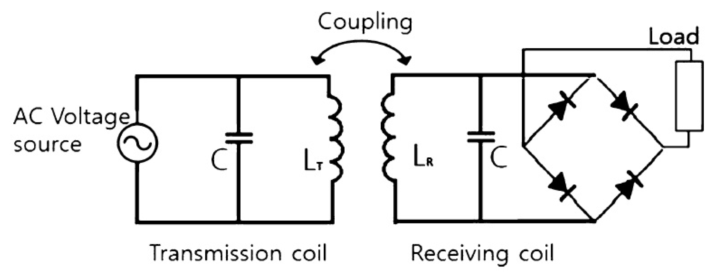
Non-resonant coupled inductors, such as typical transformers, need a magnetic core and require the magnetic field to be covered by the secondary wire in a sufficiently short range. Large distances and resistive losses make the non-resonant induction coupling highly inefficient, which can be improved by using resonant coupling of the coils. For resonant coupling, an LC circuit consisting of an inductor (coil) and a capacitor is used on transmitter and receiver sides resonating at the same frequency which allows significant power transmission between the coils over a range of a few times the coil diameters at a reasonable efficiency. A basic resonant circuit used for the resonant coupling and power transfer using an AC source is shown in Figure 2 [3].
To energize the coil at the transmitter end, one needs to convert a DC input to an AC output because the mutual induction only happens with AC. For this purpose, there is a need for an inverter design that converts the DC input to the AC output. This inverter should be designed so as to minimize the conversion losses and to convert the input power with the maximum efficiency. After successful WPT, the transferred AC is rectified via a bridge circuit. The filtration of the rectified DC current allows the usage of wirelessly transferred power for an output load such as a UAV’s battery [3].

2.2. Unmanned Aerial Vehicle Platform

In this study, a commercial quadcopter AR.Drone 2.0, developed by Parrot Inc. (Paris, France), was utilized for the demonstration of proposed concept. A bottom camera on the drone was utilized for visual sensory information for target detection. The quadrotor communicates with the ground station through Wi-Fi access point for receiving flight data and video, and transmitting control commands. Roll, pitch, yaw and throttle commands being sent to the quadrotor are in floating point values between −1 and 1. The quadcopter has an onboard attitude and heading reference system (AHRS) consisting of 3-axis accelerometers, gyroscopes, and a magnetometer. The quadcopter has its attitude stabilization which allows it to hover over a given position.

2.3. Control Scheme for Autonomous Charging and Persistent Mission

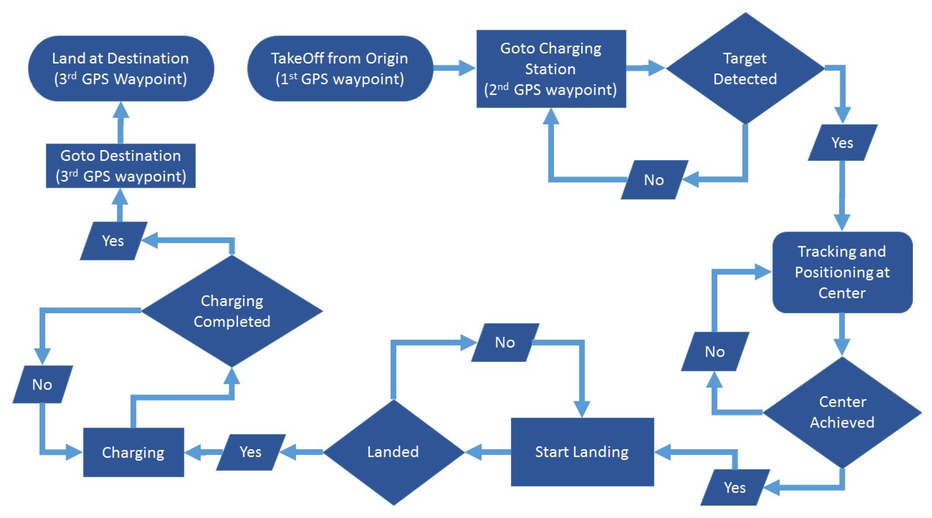
To test the autonomous charging and persistent mission, flight mission of the AR.Drone was started from the point of origin (first GPS waypoint) to reach the destination (third GPS waypoint). The experiment is designed to test the prolonged and persistent autonomous flight. Due to the reduced battery capacity (normal AR.Drone battery is 1000 mAh; capacity of the battery used in the experiment is 500 mAh), an AR.Drone is not able to reach the destination unless it stops at the mid-point (second GPS waypoint) for recharging. To perform this task autonomously, the AR.Drone was programmed to fly to a destination point, and, during the flight, the drone detects and tracks the charging platform that is on its way to the destination. Once the UAV detects the charging station, it lands and the charging process is started. During the charging, the AR.Drone continuously monitors the battery status. Once the battery is fully charged, UAV continues its mission towards the destination. Figure 3 elaborate the above-mentioned control scheme.

3. Experimental Setup

3.1. System Configuration

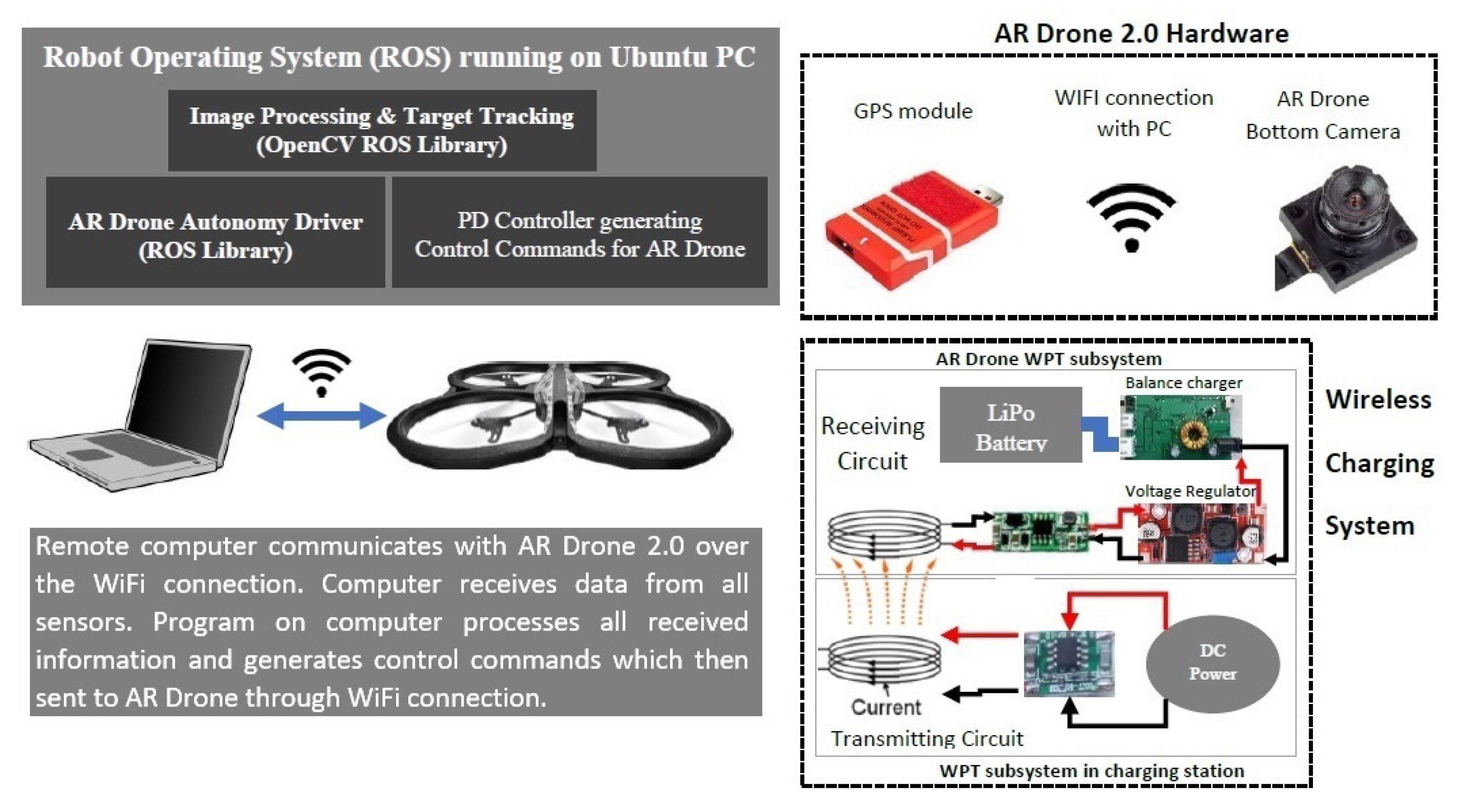
Figure 4 illustrates the system configuration. AR.Drone 2.0 and its hardware (GPS and bottom camera) also need provide manufacturers is utilized as main sensing devices. By using the open source AR.Drone autonomy driver for robot operating system (ROS) and the quadrotor’s Wi-Fi access, control commands can be transmitted, and flight data and video can be received. The proportional-derivative (PD) controller based on target detection algorithm generates tracking commands while landing on the charging platform. The onboard WPT electronics on AR.Drone allows the UAV to charge itself. The landing station have transmitting coils and WPT electronics to power the charger on an AR.Drone. The charging station is powered by external power supply.

3.2. Wireless Charging Station

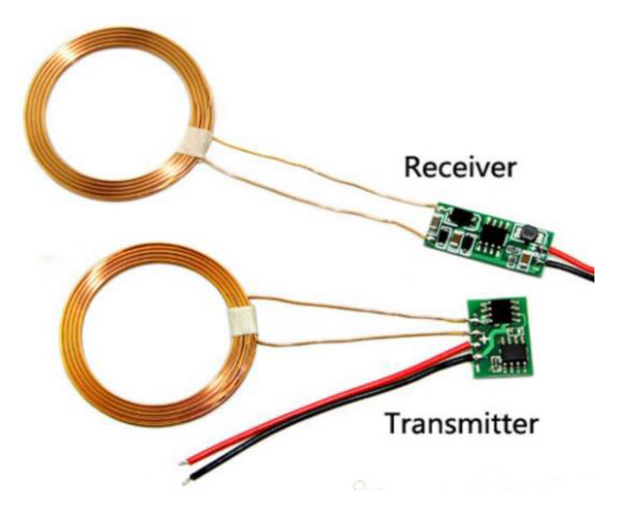
In order to successfully perform charging of the UAV, a wireless charging platform is built by utilizing an XKT-510 IC based wireless charging module (ElecFreaks) (Figure 5). XKT-510 IC has a wide voltage range of 3-15VDC on the transmitting side. Maximum current rating at peak efficiency of 1 module is 0.8 A. The maximum output wireless power transfer is 10 W. The outer and inner diameter of the transmitter/receiver coils is 22 mm and 10 mm, respectively, with inductance of 20 μH. Operating temperature range is in the range of −55 °C to 125 °C which is suitable for the outdoor environment
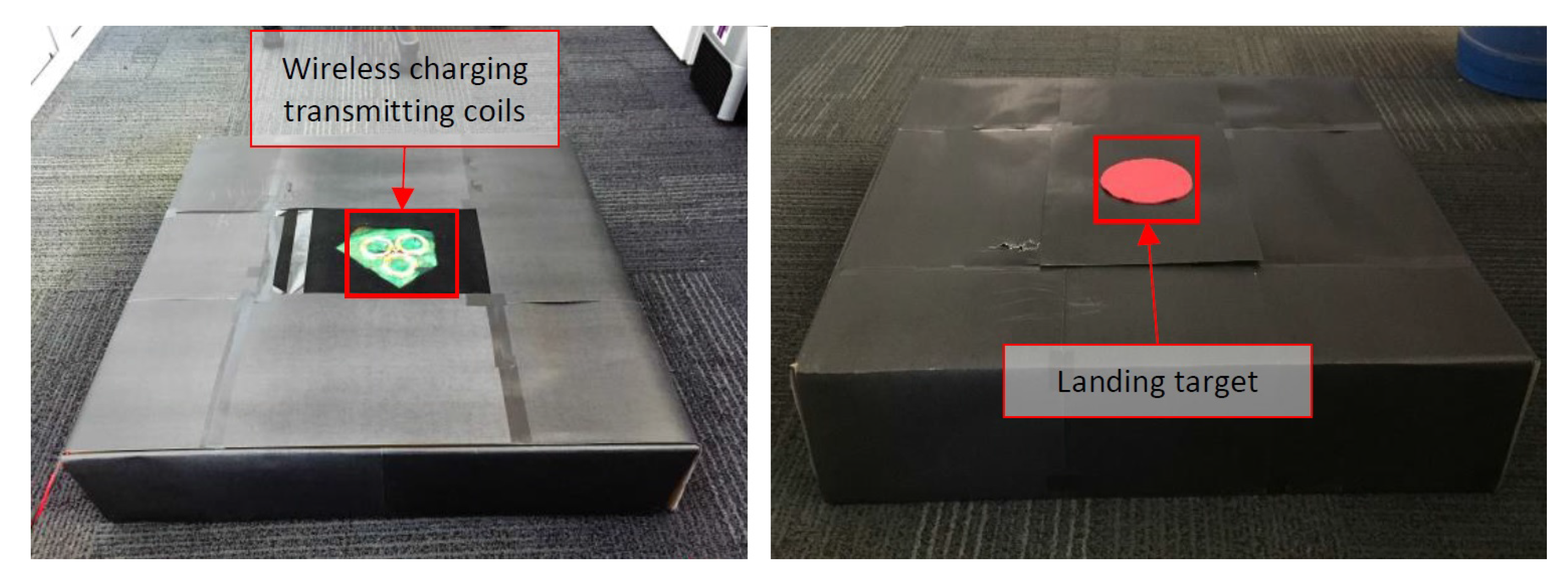
Landing Platform/Wireless charging station consists of a protective container with wireless charging electronics inside. Three XKT-510 based wireless charging modules are connected to the high capacity battery for power supply, which is included inside the station. Transmitter coils are mounted to the lid outside of the wireless charging container, which is then covered with the red circular target that is detected by the UAV for aligning and landing on the transmitter coils. Figure 6 shows the wireless charging platform with WPT electronics and target for landing.
AR.Drone 2.0 was modified and equipped with wireless charging capability. Three receiving coils connected in series are mounted to the bottom part of AR.Drone body. All three receiving circuits with integrated rectifying sub-circuits are protected and sealed with an insulator and mounted on the sides of AR.Drone body. The resulting output of receiving circuits is converted from 36 V to 12 V with a step up/down voltage regulator that is mounted on top of the AR.Drone body. Stable and filtered output from the voltage regulator circuit built around LM25575 IC (Texas Instruments, Dallas, TX, USA) and has a filtering sub-circuit for stable voltage output. LM25575 IC is then connected to a Lipo battery balance charger. The balance charger is set to charge at 0.6 A with 10 mV balance accuracy. When a drone lands on the wireless charging station, the balance charger is then powered with the onboard wireless charging system and starts charging its battery. At the same time, the AR.Drone controller monitors battery voltage, which can be accessed from the remote computer. When overall battery charge status approaches 100%, take off command is sent to the AR.Drone and resumes the mission. Figure 7 shows the wireless charging incorporated on the AR.Drone.

3.3. Target Detection Algorithm

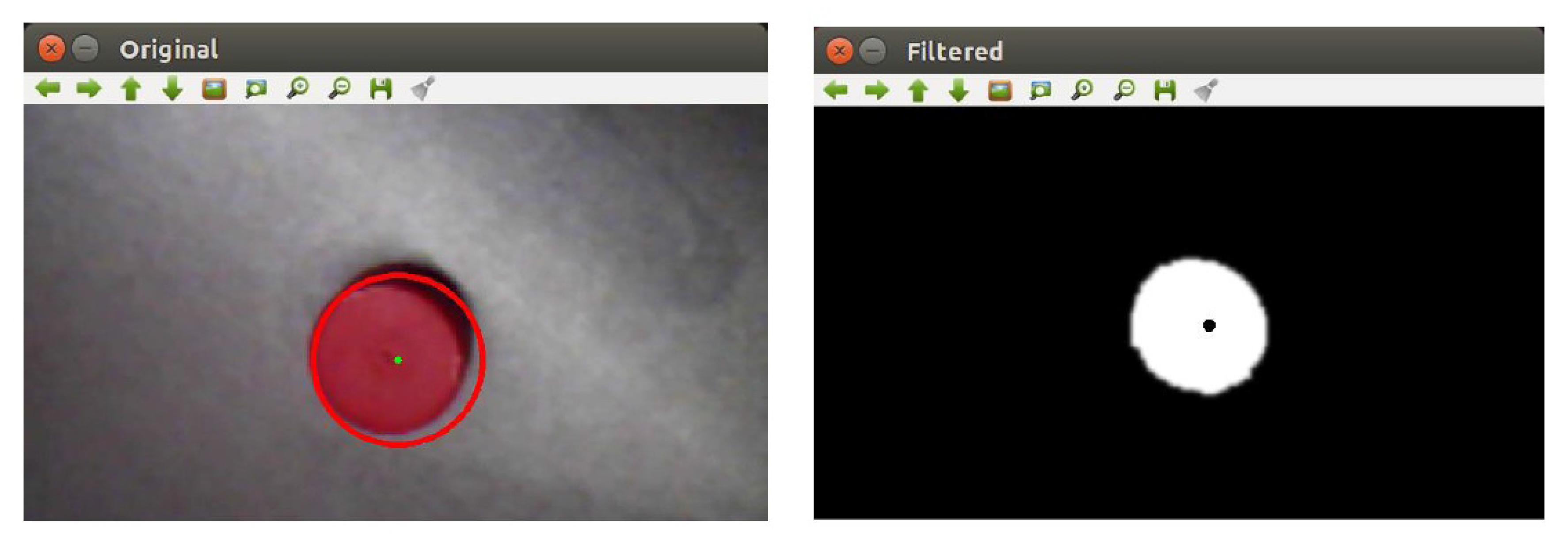
Image processing algorithm for target detection is implemented by using the open source computer vision library called OpenCV [21]. The library is integrated with ROS providing programming functions mainly aiming for real-time computer vision. A remote computer connected to AR.Drone 2.0 over the WiFi connection receives video from the onboard bottom camera of the quadcopter and stores video in ROS native image format, which is then converted to a native OpenCV image format with ROS package (CV_bridge). This image format conversion is followed by transferring RGB colour space to HSV colour space, which allows for binary conversion of the image by filtering out all unnecessary saturation, hue and value range from HSV colour space parameters. HSV filtering focuses on the red colour, as the aim is to detect a red circular target. After filtering out red, morphological operations (dilation, erosion) smoothen the the binary image from background noise. Gaussian blur filter is applied to further smoothen the image after morphological operations and make the resultant image appropriate for object detection. The filtered image is then analysed with Hough circle transform (OpenCV function) based on Hough gradient method, which is more efficient for circle detection than Hough transform and uses fewer computer resources. Figure 8 shows the processed image using the video feedback from the AR.Drone camera.

3.4. Tracking Control Based on Camera

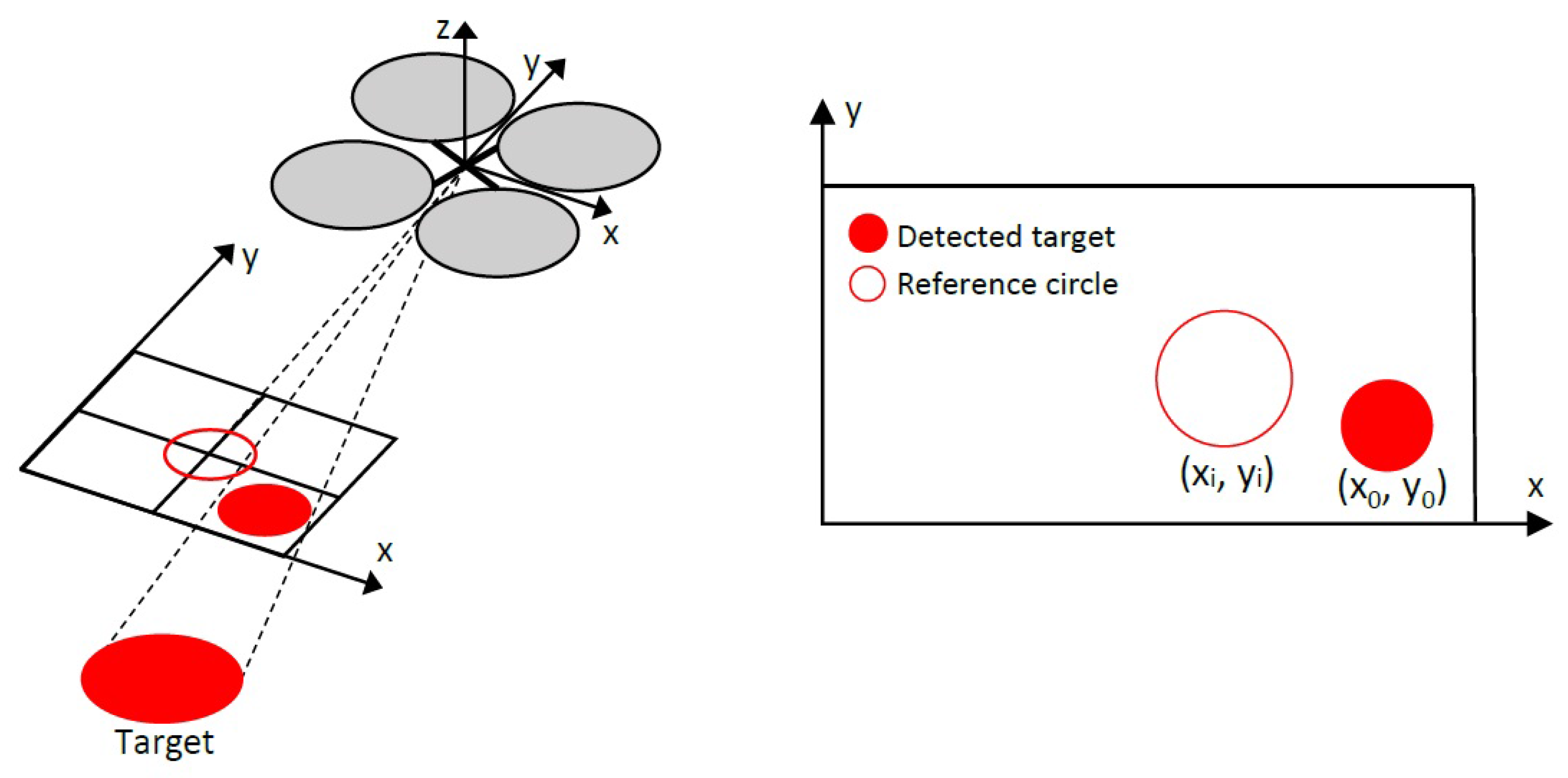
The quadrotor maneuvers above the landing station in a certain way that the detected target comes at the center of the camera image frame. The control commands for the AR.Drone are expressed as follows:
u = [ u ϕ u θ ] T ,
where u ϕ and u θ represent the roll and pitch, respectively. These values are between −1 and 1. The omnidirectional ability of wireless power transfer allows for focusing only on alignment precisely on the x- and y-axes. Hence, the yaw angle is not changed/altered while landing. Next, a state variable that represents the position of the target in one image frame can be formulated as follows:
p i = [ x i y i ] T ,
where x i and y i denote the horizontal coordinates and vertical coordinates of the target in image frame, respectively, and are measured in pixel unit. The main objective of the landing controller is to locate the target in the center of the image frame, while landing slowly and precisely on the charging station aligned with the transmitting coils. Thus, the reference state p o and the error state p e are expressed as follows:
p o = [ x o y o ] T ,
p e = p o - p i ,
where x o and y o are the center coordinates in the image frame. Then, a PD controller is developed for achieving target tracking:
u = K p p e + K d p e ˙ ,
whereas K p and K d are 2 × 2 diagonal gain matrices representing the proportional and derivative gains of each corresponding state. Gains are tuned for optimal tracking control. Position between the target and quadrotor is adjusted by the drone movement and the change is measured immediately from the camera feedback and image processing which results in closed loop control system. Furthermore, the range of the controller output is limited between −0.5 and 0.5 of input commands to the drone. In this research, a red circle is used as a target for vision-based tracking. Figure 9 shows the control procedure based on visual perception of the UAV.

4. Results and Discussion

4.1. Target Tracking and Landing

Figure 10 shows the real-time response of an AR.Drone in reducing the error state on the x- and y-axes by continuously adjusting its position using roll and pitch commands generated by the PD controller. It can be perceived that the UAV maintains its reference pixel coordinates effectively and precisely hovers over the landing target.
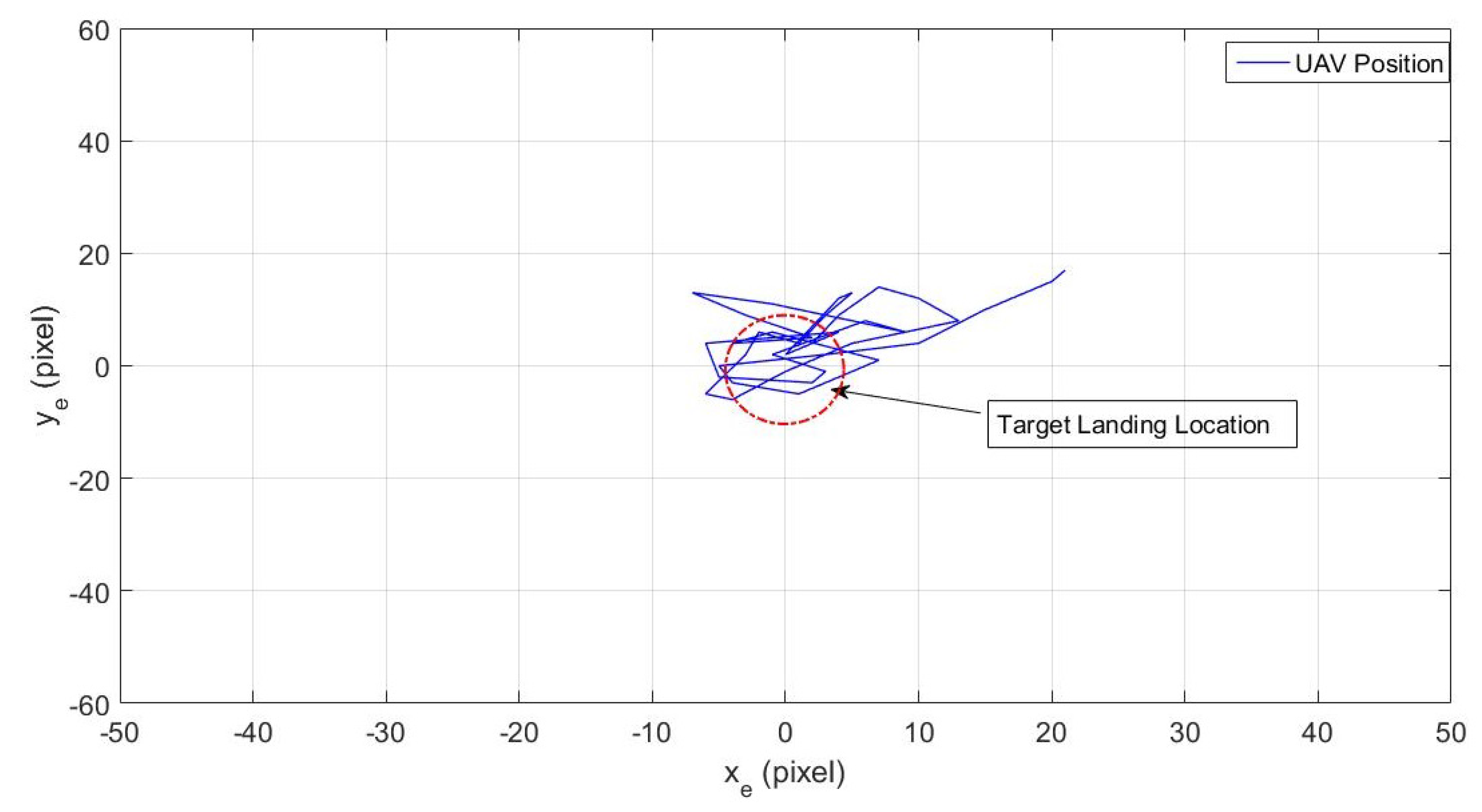
Figure 11 shows UAV hovering over the detected target in the xy pixel coordinate plane. It can be perceived that the quadcopter continuously adjusts its position according to the reference circle, eventually maintaining its hovering over the landing target.
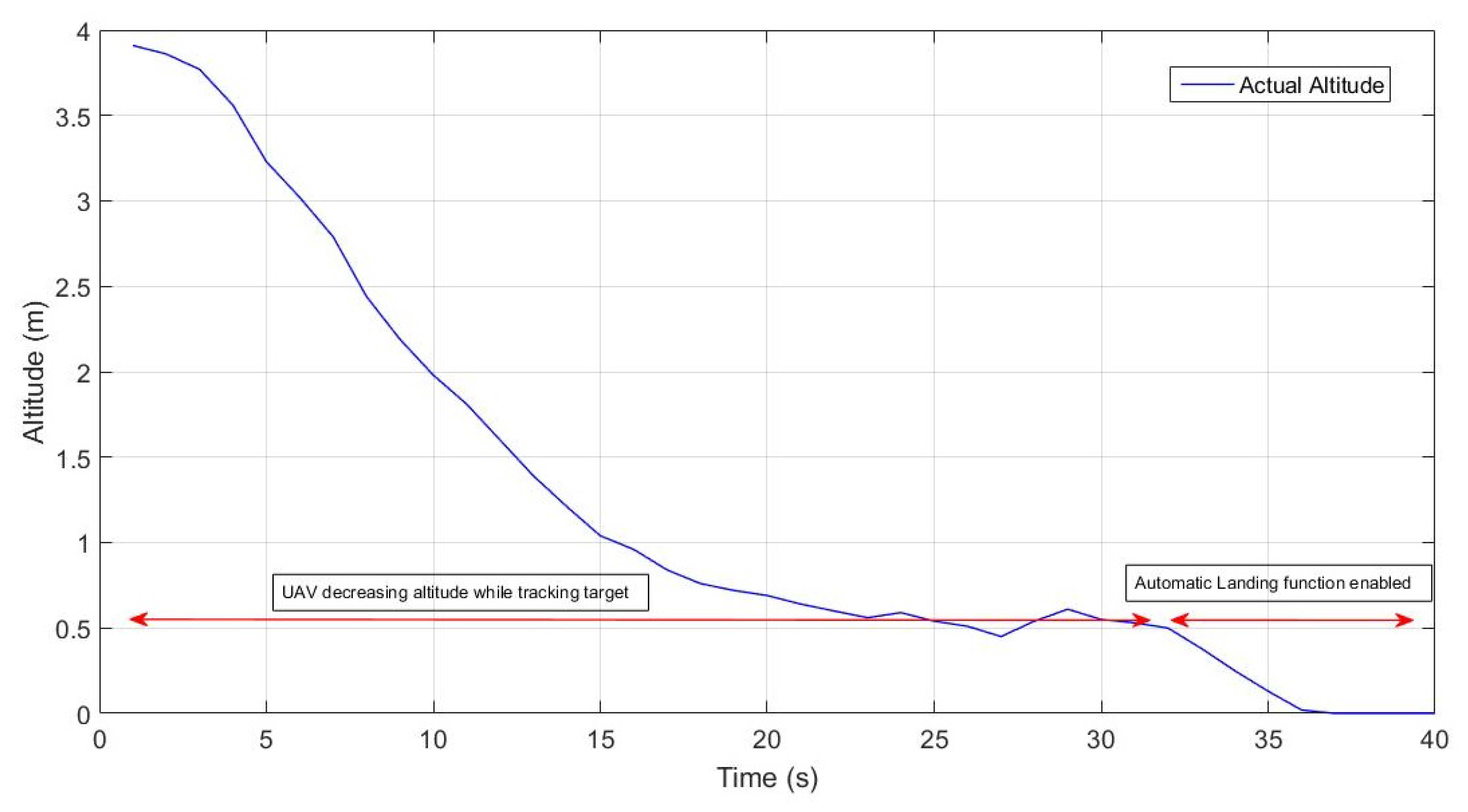
Once the drone aligns itself with the landing target, it maintains the position and hovers over the landing target. During the hovering, it gradually starts decreasing its altitude while tracking and maintaining its position over the target. When it descends to 0.5 m of height, the automatic landing function of the AR.Drone is enabled and the drone lands on the charging platform. The sonar sensor of the AR.Drone is used for acquiring the actual height. Figure 12 shows the actual height of the AR.Drone in performing the aforementioned process.
From the above mentioned results, it is observed that the proposed system performs well in the outdoor environment and successfully operates and maintains a desired position for precise landing operation over the charging station. Unlike [4,5,9,11], in which precise positioning and landing tasks are performed indoors using precise position feedback from motion capture systems, the proposed solution utilizes GPS for localizing itself generally over the landing target and uses an onboard camera for precise tracking and positioning over the landing platform. The proposed solution in this research provides the suitable control for conducting wireless charging operation in outdoor environments extending the concept of autonomous wireless charging of UAVs proposed in [3] for indoor environments.

4.2. Wireless Power Transfer Analysis

This section presents the results and analysis of the charging process using WPT. The input voltage was set to 16 V and the output voltage was regulated at 12.42 V. Figure 13 represents overall battery voltage and charging current throughout charging cycle. Charging current is steady until the balancing period with a slight increase due to increasing temperature of the system and, as a result, increasing resistance. During the cell balancing stage, current fluctuates because the balance charger feeds power only to the cells with lower voltages in order to equalise the voltage of all three cells in the battery pack. The voltage of the battery increases very fast at the start of charging cycle. After just 5 min into the charging process, battery voltage increases considerably slower in a linear manner. During the last 10 min into the charging process, the rate of battery voltage increase becomes subtle due to the fact that during balancing only specific cells gain charge. A full charging cycle lasts approximately 1 h.
The maximum WPT efficiency, with balanced charging rate of 0.5 A set on a balance charger, is calculated to be 75% at a minimum distance from the receiving coil. The efficiency was calculated using the ratio of output to input power as follows:
E = V o × I o V i × I i % ,
where E = wireless charging efficiency in percentage, V o = output voltage, I o = output current, V i = Input voltage, I i = input urrent.
Figure 14 illustrates the wireless power transfer efficiency over the charging time. Average efficiency of the WPT system is approximately 75%. A wireless charging system was loaded to approximately 50% of its load capacity. However, during the cell balancing period, when load decreases, efficiency decreases because the system performs more efficiently during noticeable loads. The achieved WPT efficiency turns out to be reasonable and feasible for the proposed application in this research. The proposed solution results here in a reasonable efficiency of an average of 75% as compared to existing works, which reported maximum efficiency of 52% and an average efficiency of 46.4%, respectively [22,23]. In this research, WPT efficiency has been improved from the previous work as well [3].
Therefore, the obtained WPT results here sufficiently demonstrate the effectiveness of the proposed solution and its practical usefulness for real UAVs in outdoor environment, which is the clear novelty of the present research work.

4.3. Persistent Mission with Prolonged Flight

This research demonstrated the concept of autonomous wireless charging for UAVs, which was previously performed in indoor environments [3]. The proposed research provides the solution for the persistent autonomous mission without involving any human intervention in the outdoors, resulting in increased endurance and prolonged flight for conventional UAV applications. Figure 15 shows the snapshots of the different processes, which demonstrates the implementation of autonomous wireless charging capability in outdoor environments enhancing the flight time. The tracking control based on visual feedback from the camera allows precise tracking of charging station, and controlled and accurate landing on the target platform.

5. Conclusions

In this research, an autonomous wireless charging system for a persistent mission of UAVs was proposed. Target detection and tracking algorithm, for AR.Drone quadrotor equipped with a bottom camera and GPS, was developed to provide the ability for the UAV to detect, track and land precisely on the charging station. A red circular target on the top of a charging station allows the UAV to successfully detect and track the landing position. The main strategy of the algorithm was to maintain its relative center position in an image frame with respect to the target using measurements of the captured image frame. It was observed that the system could smoothly locate and track the target, and the UAV was able to land precisely on the station in outdoor environments.
Furthermore, the introduction of wireless charging in the quadcopter provided the ability for a persistent mission without any human intervention. The flight time of present quadcopters is highly limited due to the battery capacity. Wireless charging enables the UAVs to charge autonomously while flying towards their destinations, thereby continuing the mission after being recharged without any external interruption. This introduces the ability to carry out the missions that demand long flight times without any human intervention. The present research successfully demonstrated this ability by performing a mission from the first GPS waypoint to the third GPS waypoint. The distance between the origin and destination is almost double the distance that a normal UAV can fly. However, with the proposed solution, the increased endurance and prolonged flight time is added to a normal UAV. It can now charge at the second GPS waypoint that is at the mid-way. Average WPT efficiency of the charging system is 75%, which is feasible for performing the charging operation for UAVs.
The integration of wireless charging ability into UAVs in outdoor environments opens up different directions to be researched. A solar power panel can be installed with the charging system if it needs to be placed in a remote area. Furthermore, the technique of fast charging of the Lipo batteries can be researched and incorporated into the wireless charging station, which will decrease the charging time, resulting in decreased total mission time. Future work will also include the development of a robust controller for severe weather conditions, as the proposed concept is focused mainly on the operations of UAVs in remote areas where the weather conditions may be more disturbing and severe.

Acknowledgments

This work was funded by Kingston University, London, UK.

Author Contributions

Ali Bin Junaid built the hardware, conducted the tests and wrote the paper; Aleksay Konoiko and Ali Bin Junaid developed the image processing and target tracking algorithms; Yahya Zweiri developed the control scheme of the system; and M. Necip Sahinkaya and Lakmal Seneviratne reviewed and edited the manuscript.

Conflicts of Interest

The authors declare no conflict of interest.

Abbreviations

GPSGlobal Positioning System
LiPoLithium Polymer
PDProportional-Derivative
ROSRobot Operating System
UAVUnmanned Aerial Vehicle
VTOLVertical Take-Off and Landing
WPTWireless Power Transfer

References

  1. Mahony, R.; Kumar, V. Aerial robotics and the quadrotor [from the guest editors]. IEEE Robot. Autom. Mag. 2012, 19, 19. [Google Scholar] [CrossRef]
  2. Lima, P.; Ribeiro, M.I. Santos-victor the rescue project-cooperative navigation for rescue robots. In Proceedings of the 1st International Workshop on Advances in Service Robotics, Verona, Italy, 13–15 March 2003. [Google Scholar]
  3. Junaid, A.B.; Lee, Y.; Kim, Y. Design and implementation of autonomous wireless charging station for rotary-wing UAVs. Aerosp. Sci. Technol. 2016, 54, 253–266. [Google Scholar] [CrossRef]
  4. Dale, D.R. Automated Ground Maintenence and Health Management for Autonomous Unmanned Aerial Vehicles. Master’s Thesis, Massachusetts Institute of Technology, Cambridge, MA, USA, 2007. [Google Scholar]
  5. Valenti, M.; Dale, D.; How, J.; Pucci de Farias, D.; Vian, J. Mission health management for 24/7 persistent surveillance operations. In Proceedings of the AIAA Guidance, Navigation and Control Conference and Exhibit, Hilton Head, SC, USA, 20–23 August 2007. [Google Scholar]
  6. Silverman, M.C.; Jung, B.; Nies, D.; Sukhatme, G.S. Staying Alive Longer: Autonomous Robot Recharging Put to the Test; Center for Robotics and Embedded Systems (CRES) Technical Report; University of Southern California: Los Angeles, CA, USA, 2003. [Google Scholar]
  7. Swieringa, K.A.; Hanson, C.B.; Richardson, J.R.; White, J.D.; Hasan, Z.; Qian, E.; Girard, A. Autonomous battery swapping system for small-scale helicopters. In Proceedings of the 2010 IEEE International Conference on Robotics and Automation, Anchorage, AK, USA, 3–8 May 2010; pp. 3335–3340. [Google Scholar]
  8. iRobot Corporation. Available online: http://www.irobot.com/ (accessed on April 2015).
  9. Augugliaro, F.; Lupashin, S.; Hamer, M.; Male, C.; Hehn, M.; Mueller, M.W.; Willmann, J.S.; Gramazio, F.; Kohler, M.; D’Andrea, R. The flight assembled architecture installation: Cooperative construction with flying machines. IEEE Control Syst. 2014, 34, 46–64. [Google Scholar] [CrossRef]
  10. Vicon Motion Systems Ltd. Available online: http://www.vicon.com/ (accessed on April 2016).
  11. Leonard, J.; Savvaris, A.; Tsourdos, A. Energy management in swarm of Unmanned Aerial Vehicles. In Proceedings of the 2013 International Conference on Unmanned Aircraft Systems (ICUAS), Atlanta, GA, USA, 28–31 May 2013; pp. 124–133. [Google Scholar]
  12. Voos, H.; Bou-Ammar, H. Nonlinear tracking and landing controller for quadrotor aerial robots. In Proceedings of the 2010 IEEE International Conference on Control Applications, Yokohama, Japan, 8–10 September 2010; pp. 2136–2141. [Google Scholar]
  13. Lee, D.; Ryan, T.; Kim, H.J. Autonomous landing of a VTOL UAV on a moving platform using image-based visual servoing. In Proceedings of the 2012 IEEE International Conference on Robotics and Automation, St. Paul, MN, USA, 14–18 May 2012; pp. 971–976. [Google Scholar]
  14. Wenzel, K.E.; Masselli, A.; Zell, A. Automatic take off, tracking and landing of a miniature UAV on a moving carrier vehicle. J. Intell. Robot. Syst. 2011, 61, 221–238. [Google Scholar] [CrossRef]
  15. Kurs, A.; Karalis, A.; Moffatt, R.; Joannopoulos, J.D.; Fisher, P.; Soljačić, M. Wireless power transfer via strongly coupled magnetic resonances. Science 2007, 317, 83–86. [Google Scholar] [CrossRef] [PubMed]
  16. Karalis, A.; Joannopoulos, J.; Soljačić, M. Efficient wireless non-radiative mid-range energy transfer. Ann. Phys. 2008, 323, 34–48. [Google Scholar] [CrossRef]
  17. Griffin, B.; Detweiler, C. Resonant wireless power transfer to ground sensors from a UAV. In Proceedings of the 2012 IEEE International Conference on Robotics and Automation, Guangzhou, China, 11–14 December 2012; pp. 2660–2665. [Google Scholar]
  18. Khonji, M.; Alshehhi, M.; Tseng, C.M.; Chau, C.K. Autonomous inductive charging system for battery-operated electric drones. In Proceedings of the Eighth International Conference on Future Energy Systems, Hong Kong, China, 16–19 May 2017; pp. 322–327. [Google Scholar]
  19. Zhao, D.; Chen, W.; Al-Maharmah, R.; Kang, S.; Lim, S.O.; Bruck, G.; Jung, P. Magnetic field forming of spatial multiple antennas for wireless power transfer. In Proceedings of the 2012 International Symposium on Antennas and Propagation (ISAP), Nagoya, Japan, 29 October–2 November 2012; pp. 1204–1207. [Google Scholar]
  20. Kim, J.; Shim, D.H.; Morrison, J.R. Tablet PC-based visual target-following system for quadrotors. J. Intell. Robot. Syst. 2014, 74, 85–95. [Google Scholar] [CrossRef]
  21. OpenCV. Available online: http://www.opencv.org/ (accessed on April 2016).
  22. Zhang, J.; Song, G.; Li, Y.; Qiao, G.; Li, Z. Battery swapping and wireless charging for a home robot system with remote human assistance. IEEE Trans. Consum. Electron. 2013, 59, 747–755. [Google Scholar] [CrossRef]
  23. Han, S.; Wentzloff, D.D. Wireless power transfer using resonant inductive coupling for 3D integrated ICs. In Proceedings of the 2010 IEEE International 3D Systems Integration Conference (3DIC), Munich, Germany, 16–18 November 2010; pp. 1–5. [Google Scholar]
Figure 1. Typical block diagram for wireless power transfer.
Energies 10 00803 g001
Figure 2. Typical block diagram for wireless power transfer [3].
Energies 10 00803 g002
Figure 3. Proposed scheme for the persistent unmanned aerial vehicle mission.
Energies 10 00803 g003
Figure 4. System diagram.
Energies 10 00803 g004
Figure 5. XKT-510 IC based wireless charging module.
Energies 10 00803 g005
Figure 6. (Left) charging station with Transmitter coils; (right) red circular target for tracking and landing.
Energies 10 00803 g006
Figure 7. (Left) AR.Drone integrated with a voltage regulator and balance charger; (right) WPT receiving coils connected in series.
Energies 10 00803 g007
Figure 8. (left) Original Image; (right) processed Image.
Energies 10 00803 g008
Figure 9. (Left) Unmanned aerial vehicle and circular red target; (right) target and reference position in image frame.
Energies 10 00803 g009
Figure 10. Graph of error state variables, (left) x e and (right) y e .
Energies 10 00803 g010
Figure 11. AR.Drone hovering and maintaining the center position over the detected target.
Energies 10 00803 g011
Figure 12. Unmanned aerial vehicle decreasing altitude while tracking and landing.
Energies 10 00803 g012
Figure 13. Battery voltage and charging current during charging.
Energies 10 00803 g013
Figure 14. Wireless power transfer efficiency during charging.
Energies 10 00803 g014
Figure 15. (a) Take-off from origin; (b) flying to charging station; (c) tracking target and positioning for landing; (d) landed and charging; (e) take-off and flying towards destination.
Energies 10 00803 g015