Article

Analysis and Prevention of Geo-Environmental Hazards with High-Intensive Coal Mining: A Case Study in China’s Western Eco-Environment Frangible Area

1
Key Laboratory of Deep Coal Resource Mining, School of Mines, Ministry of Education of China, China University of Mining and Technology, Xuzhou 221116, China
2
School of Civil, Environmental and Mining Engineering, The University of Western Australia, Perth 6009, Australia
*
Author to whom correspondence should be addressed.
Energies 2017, 10(6), 786; https://doi.org/10.3390/en10060786
Submission received: 13 April 2017 / Revised: 8 May 2017 / Accepted: 4 June 2017 / Published: 7 June 2017

Abstract

:
This study seeks to address the problems of major geo-environmental hazards caused by high-intensive coal mining in China’s western eco-environment frangible area including strong mining pressure, surface subsidence, soil and water loss, and land desertification. Using the high-intensive mining at the Xiao-jihan Coal Mine, this paper investigates the compaction characteristics of aeolian sand-based backfilling materials, and then the evolution of water-conducting fractures and surface deformation laws with different backfill material’s compression ratios (BMCRs) by using physical simulation and numerical simulation analysis methods. This study presents the technical system of water-preserved and environmental protection with rapid-backfilling methods in China’s western eco-environment frangible area. The backfill coal mining technique and application prospects are assessed and discussed. The results will be helpful for coordinated development of coal resources exploitation and environmental protection in China’s western eco-environment frangible area.

1. Introduction

China’s West Development Program has encouraged rapid urbanization and industrialization in western China, resulting in intense coal resource exploitation [1]. At the same time, the eastern coal resources have become increasingly scarce, which has contributed to the acceleration of the construction of coal resource centers and strategic bases. Coal resource exploitation has gradually shifted to the western areas, which has contributed to the rapid development of the western local economy and is consistent with the concept of the “Silk Road economic belt”, put forward by Chinese President, Xi Jinping [2]. However, with the continuing developments and innovations in coal production technology and processes, the mining and production capacities and of coal mines have also increased in intensity. The production capacity of new large coal mines generally reaches 10 million tons with the longwall panel length reaching 300 m in the dip direction, the mining height reaching 5 m, and the advancing speed reaching 20 m/d. The annual production capacity of a single longwall panel is the sum of a dozen longwall panels in an eastern coal mine [3].
Theoretical research and field measurement show that coal resource exploitation can easily result in environment damage in western China [4,5,6]. Common environmental problems and hazards caused by shallow buried depth coal mining under a thick, loose sand layer include strong mining pressure with hydraulic support damage (Figure 1a), surface subsidence (Figure 1b), surface fissures and water loss (Figure 1c), and land desertification (Figure 1d). To respond to the effects of phreatic pore water in the loose beds of the Quaternary system and the thick surface layer of aeolian sand, many coal mines in China’s western area pump water before mining, use a combination of pumping and mining during coal resource exploitation, or adopt the room mining method where large coal pillars are left behind underground; these methods result in a significant waste of water and coal resources. A solution is urgently needed that will allow for social and economic development as well as ensuring for the harmonious development of the western coal mining area. The search for a reasonable mining method is very important.
In recent years, solid backfill mining (SBM) technology has gained popularity in China [7,8,9,10]. This technology has obvious economic and environmental benefits for exploiting coal resources under buildings, bodies of water, railways, and for controlling strata movement [11,12,13,14,15]. So far, the technology has been successfully applied in more than twenty mining areas in China. Most of the mining areas are coal resource-exhausted mines. The remaining coal resources can be found under villages in eastern China. The backfill material is mainly composed of crushed waste rock of gangue ground piles. Nevertheless, considering the special mining and geological conditions in western China, backfill materials (e.g., gangues and solid waste) are not very abundant; the resulting high cost of backfill greatly limits its application. However, the abundant aeolian sand on the surface in the western coal mining area provides the basic conditions for the smooth implementation of the technology. There have not been any comprehensive studies regarding mining technology in China’s western area. In consideration of the long-term development and the ecological protection of the western mining area, research on the technical systems and applications of effect evaluation is of great significance. Therefore, there is significant need for this issue to be addressed.
This paper is organized as follows: first a review of the geological and hydrogeological conditions typical of the western mining area with high-intensive coal resource exploitation is presented. This is followed by a presentation of the aeolian sand-based backfill materials and the experimental tests. Then the results of the characteristics of the fracture evolution and surface deformation in high-intensive coal resource exploitation with different BMCRs are presented and discussed. Next, the technical system and the rapid-backfill technology are established. Finally, we analyze and discuss the application perspective and present our conclusions. The goal of this study is to encourage Chinese and international scholars to further research water-preserving mining with backfill mining methods in western China.

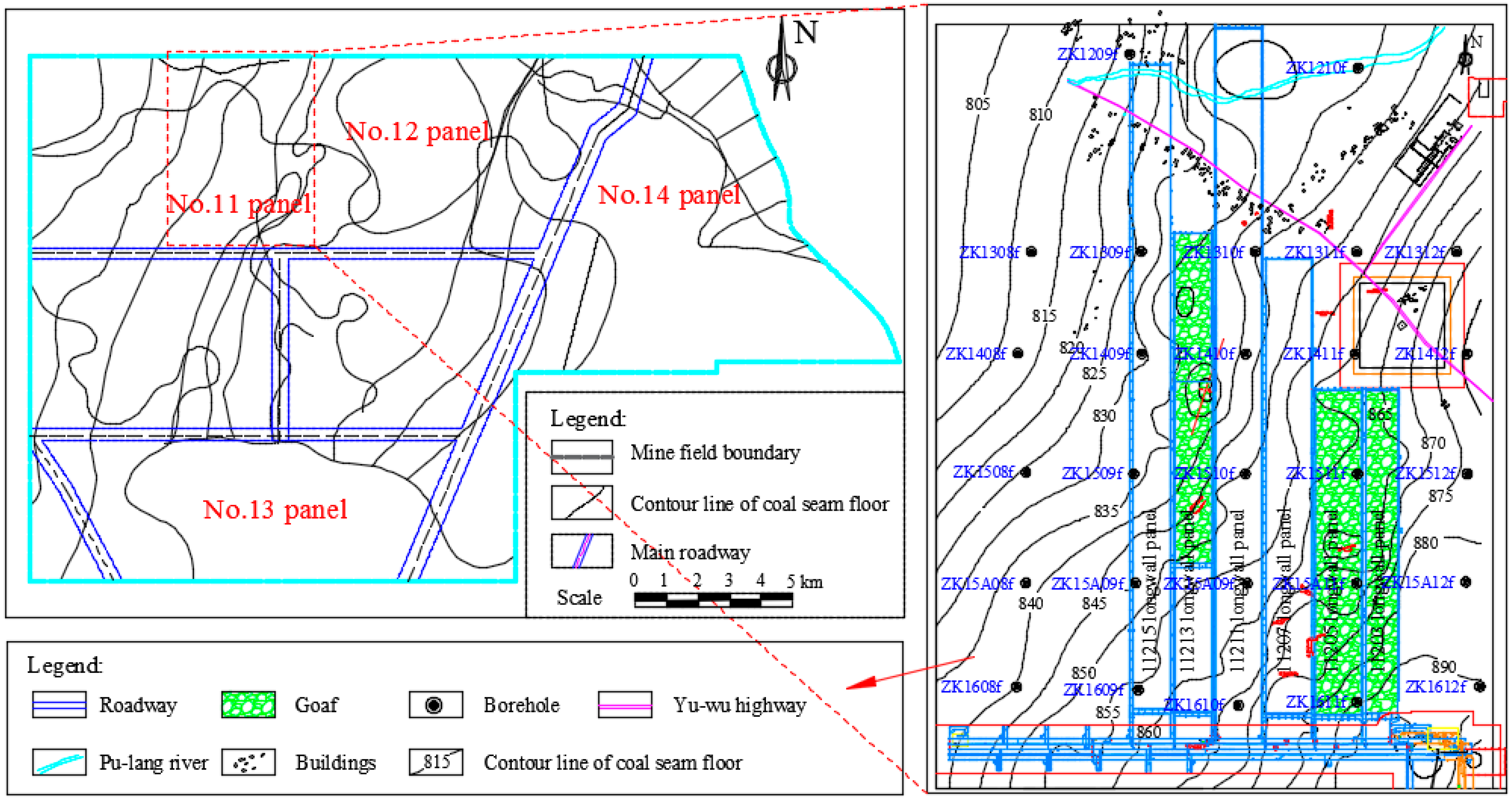
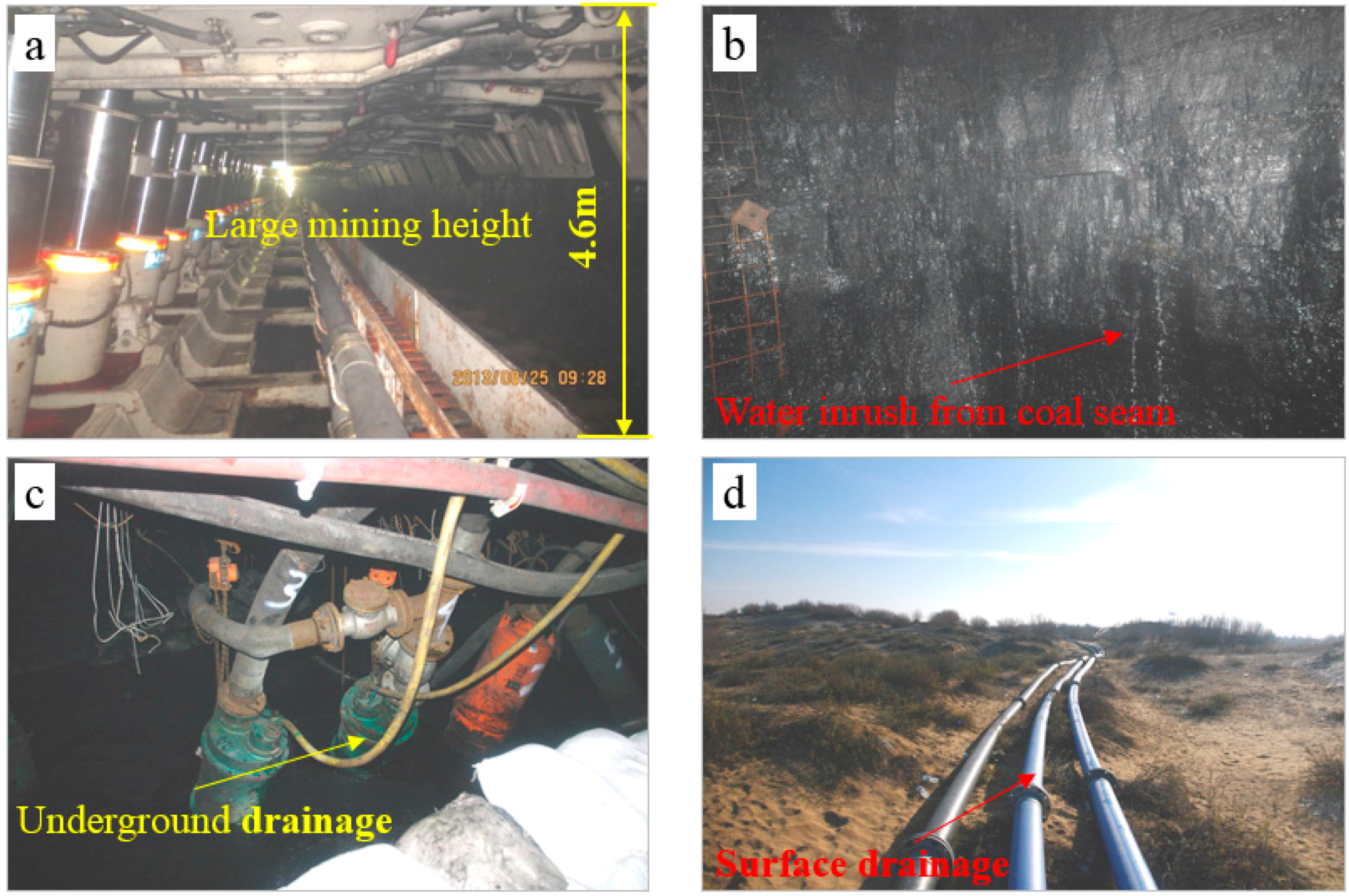
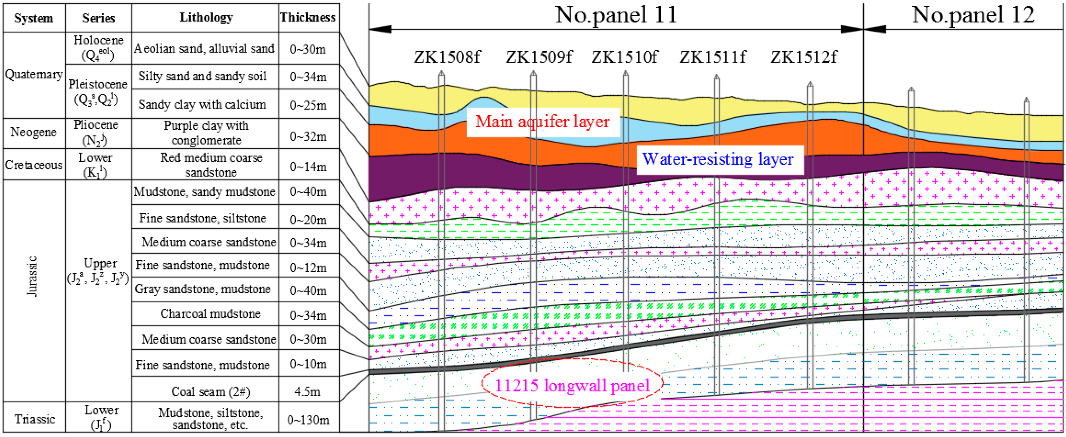
2. Study Area Description

Xiao-jihan Coal Mine, was formed during the Jurassic period and is located in the Yuheng north mining area of North Shaanxi. It is the first 10 million ton modern mine from the national program in Shaanxi Province, Yulin. The area of the mine field is about 251.75 square kilometres and it has a geological reserve of 31.7 billion tons and recoverable reserves of 18.9 billion tons. There are nine layers of coal in the mine, and the #2 coal is the main mining coal seam with a thickness of 3.25–5.04 m (average thickness is 4.5 m). The buried depth of the #2 coal seam ranges from 173.98 m to 460.36 m, and the floor elevation changes between 768.14 m and 460.36 m. The coal seam follows a northwest to west trend monoclinic dumping relief with an average drawdown extent of 12 m/km. The inner geology structure of the coal mine is simple, the east mining field is relatively gentle, and the #2 coal seam is a near horizontal coal seam. The 11,215 working face, located in the No. 11 panel, is the current mining area. The 11,213 working face to the east and the 11,217 to the west have closed borders with the 11,215 working face. The main haulage roadway and air return are located to the south of the coal mine. The advancing distance of the 11,215 working face is about 4888 m, the working face length is 280 m, the mining height is 4.5 m, the advancing speed reaches up to 16 m/d, and the production capacity is up to 10 million tons. Due to the large thickness and shallow buried depth of the coal seam, geo-environmental hazards and environmental damage phenomena (e.g., strong mining pressure, rib fall off coal wall, roof caving, and surface subsidence) continue to occur in the mining process. Figure 2 shows the longwall panel layout of the Xiao-jihan Coal Mine.
Based on analysis of the borehole data of Xiao-jihan Coal Mine, the stratigraphic column and section of No. 11 panel and No. 12 panel were obtained, as shown in Figure 3. According to the Hydrogeological testing data, the main aquifers of the mine are the phreatic aquifer in the loose bed of the Quaternary Salawusu formation, mainly composed of loose stratum with silt sand and sandy soil. This aquifer is an important water source for biological growth on the surface and has a thickness of 20–40 m. The Neogene Jingle formation and the Quaternary Lishi formation, composed mostly of sandy clay and purple clay with calcium and conglomerate, are the main water-resisting layers in this area. The hydrologic geology conditions have a significant effect on coal exploitation in Xiao-jihan Coal Mine. For example, during shaft construction, the predicted water inflow of the surface water bearing the Quaternary sand layer is 28.51 m3/h and is 15–30 m thick. However, the actual water inflow reaches more than 185 m3/h. Water or sand inrush at this rate is so serious that it affects normal construction before drainage. However, because of the effects of mining-induced stress, the overlying strata water-conducting fractures and water inrush development are obviously underground in the No. 11 panel during roadway driving and advancement of the working face (Figure 4a,b). Although some relatively effective strategies for preventing water disasters have been employed, including the transient electromagnetic method, forward boring water drainage, and pumping-drainage system ground surface (Figure 4c,d), some parts of the working face or roadway are affected seriously in the local water-enriched area. This is especially true when the roof pressure is strong or the drainage system is not unobstructed; in these cases, the efficiency and safety production will be severely affected.

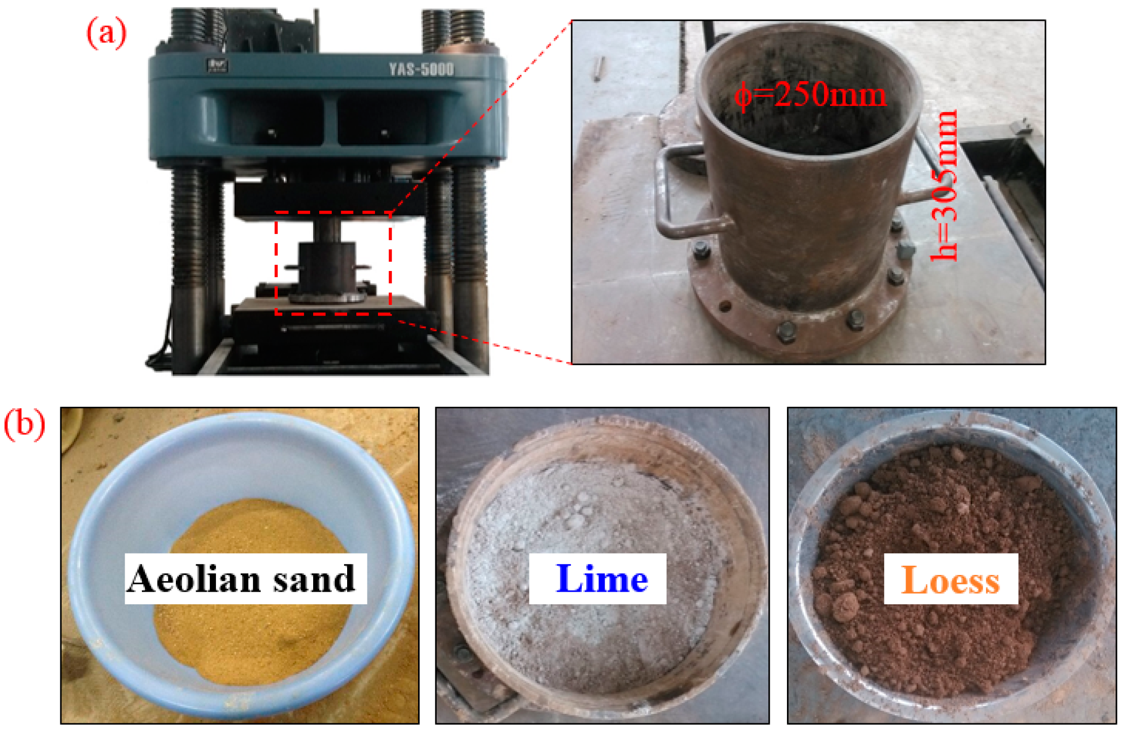
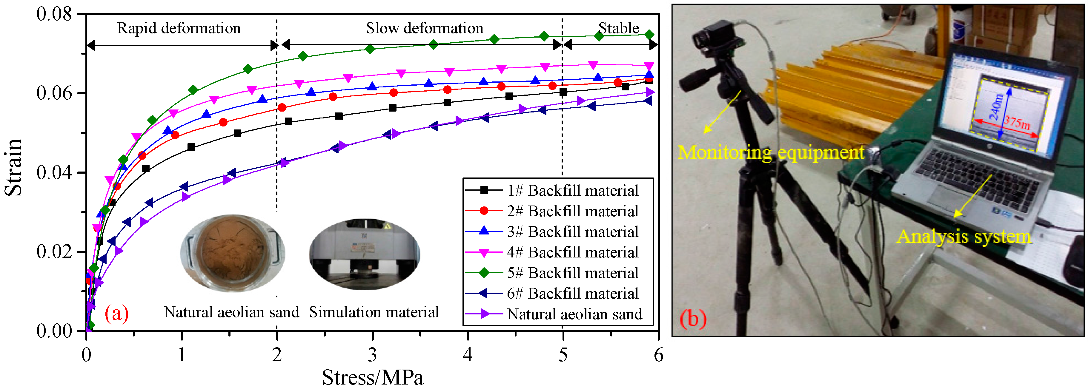
3. Backfill Material Properties Testing

It is essential to appropriately monitor overlying strata for water-conducting fracture development and surrounding rock failures, in order to promote efficient water-preservation mining and environmental protection. The testing and study of the compacting properties of aeolian-sand material for backfill is of greatly significant, considering the abundant natural aeolian sand material on the surface in China’s western mining area, combined with the mature SBM technology. The loading equipment used in this experiment was a YAS-5000 electro-hydraulic servo-motor test system (Changchun Kexin Instruments Company, Changchun, China). Additionally, a steel chamber was designed specifically for the study. The chamber had a maximum uniaxial pressure of 20 MPa and a maximum radial pressure of 13.4 MPa in its inner wall. And the height and diameter are 250 mm and 305 mm, respectively. The maximum load used was set at 6 MPa and the load was implemented at a relatively slow rate (0.15–0.20 kN/s). Testing data was collected every three seconds. Each test was repeated three times and the average of the three results was regarded as the final results [16,17]. The basic experimental testing materials include natural aeolian sand, lime and loess, the experimental equipment, and the materials shown in Figure 5. Four mix proportions were used in this experiment [18,19]; Table 1 shows the details of the test scheme and results. Figure 6 shows the results of stress-strain curves at different mix proportions.
The results shown in Table 1 and Figure 6 show that the compaction stress-strain curves of aeolian sand-based mixing materials have a logarithmic relationship. In the initial compaction stage (0–2 MPa, tamping arm pressure), the strain grows quickly and the deformation velocity is high. As the pressure gradually increases, the materials gradually compact and the changes in growth decrease. In the first scheme, the aeolian sand deformation is relatively small during the compaction process. This is mainly because of the physical characteristics including small solid particles, lack of cohesion, and bad hydrophilicity. The maximum strain is 0.055, with a stress of 5 MPa (in-situ stress), the strain ratio in 0–2 MPa to the total strain is more than 70%. In the second scheme, when the proportion of aeolian sand to loess is 1:0.3, the strain is relatively small during the compaction process, which indicates that these materials have a relatively strong deformation resisting capability. The maximum strain is 0.22 and 0.27 with stress of 2 MPa and 5 MPa, respectively. In the third scheme, the ratio of aeolian sand to lime is 1:0.12, which is a relatively small strain. The maximum strain is 0.23 and 0.27 with stress of 2 MPa and 5 MPa, respectively. In the fourth scheme, the optimal proportion of aeolian sand, loess, and lime is 1:0.3:0.1:6. When the stress is 2 MPa and 5 MPa, the strain is 0.23 and 0.26. The experimental results show that the different levels of lime and loess can restrain the compressive property of mix backfill materials. However, the lime and loess can improve the cohesiveness and self-stability of backfill materials. Therefore, different mix proportions of aeolian sand-based backfilling materials can be selected according to the different specific geological conditions. In this article, we select the single nature aeolian sand materials as the research backfill materials.

4. Fracture Evolution and Surface Deformation with High-Intensive Mining

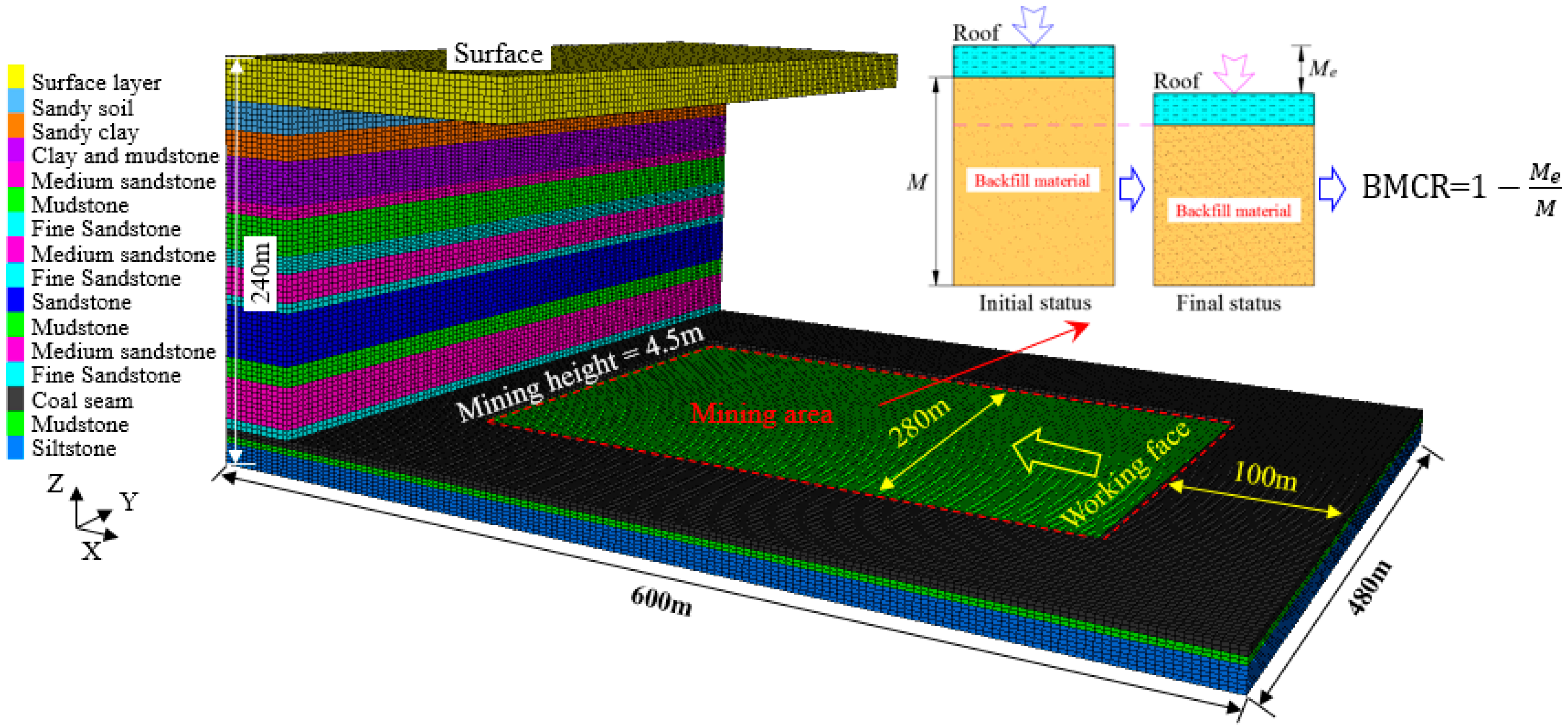
4.1. Physical and Numerical Simulation

In order to study the characteristics of geo-environmental hazards in high-intensive coal mining, we focus on the evolution of water-conducting fractures and surface deformation laws with different BMCRs by using physical simulation and numerical simulation analysis methods. The two-dimensional physical simulation was conducted to study water-conducting fracture evolution in the overlying strata at BMCRs of 0%, 70%, and 90%. According to in situ conditions, the geometric similarity constant was 1:150, the bulk density similarity constant was 1:1.67, and the time similarity constant was 1:10. The simulation model dimensions were 2.5 m × 0.2 m × 1.6 m (length × width × height). The bottom and both sides of the model were fixed, and the vertical displacement at the base of the model was set to zero. In this paper, the backfill materials in the physical simulation were composed of sponges and papers, and optimally similar materials were selected until the simulation results of the stress-strain characteristics were in good agreement with the experimental data [20,21]. During backfill coal mining, a non-contact strain measurement system and Vic-2D software were used, as shown in Figure 7. The numerical model assumes a length of 600 m in the dip direction, a width of 480 m in the strike direction, and a height of 240 m, as shown in Figure 8. The failure criterion used in the numerical analyses is the Mohr-Coulomb model. During extraction, the goaf area is filled with different soft elastic materials to approximate the different BMCRs [22,23]. The physical and numerical simulation parameters employed in the model have been scaled and adjusted using the laboratory results for the mechanical properties of the rock and coal samples; the final parameters are given in Table 2.

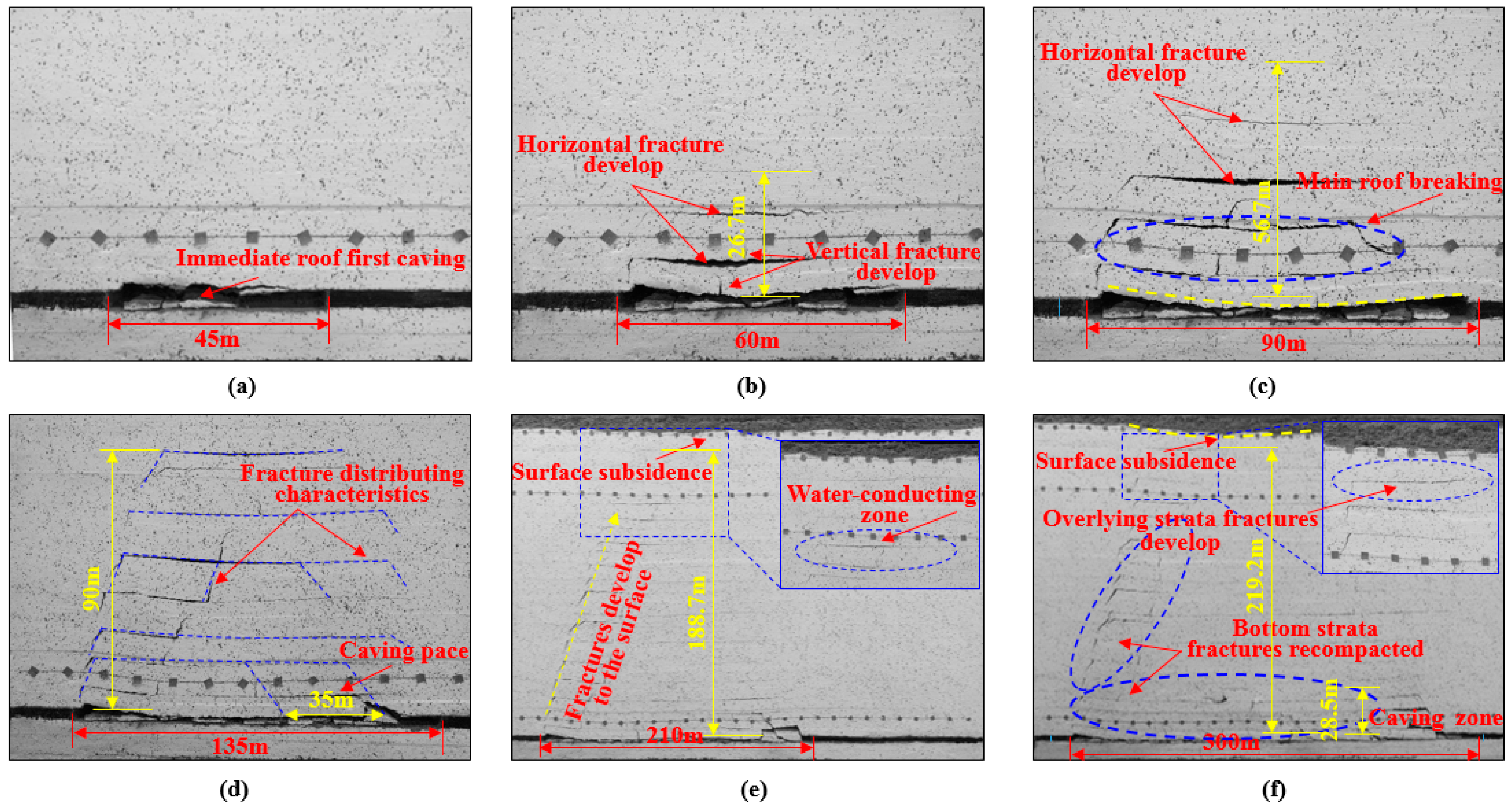
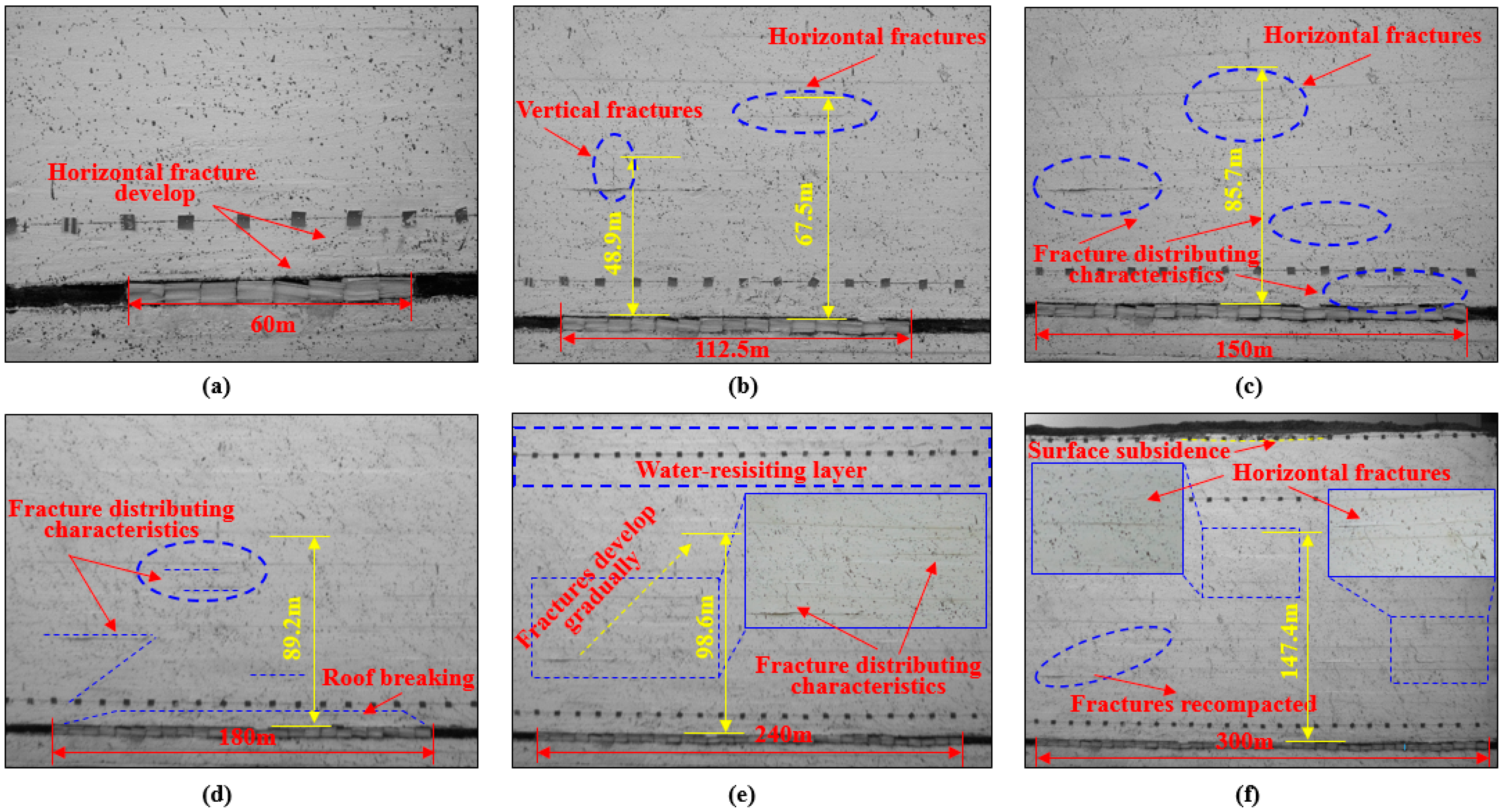
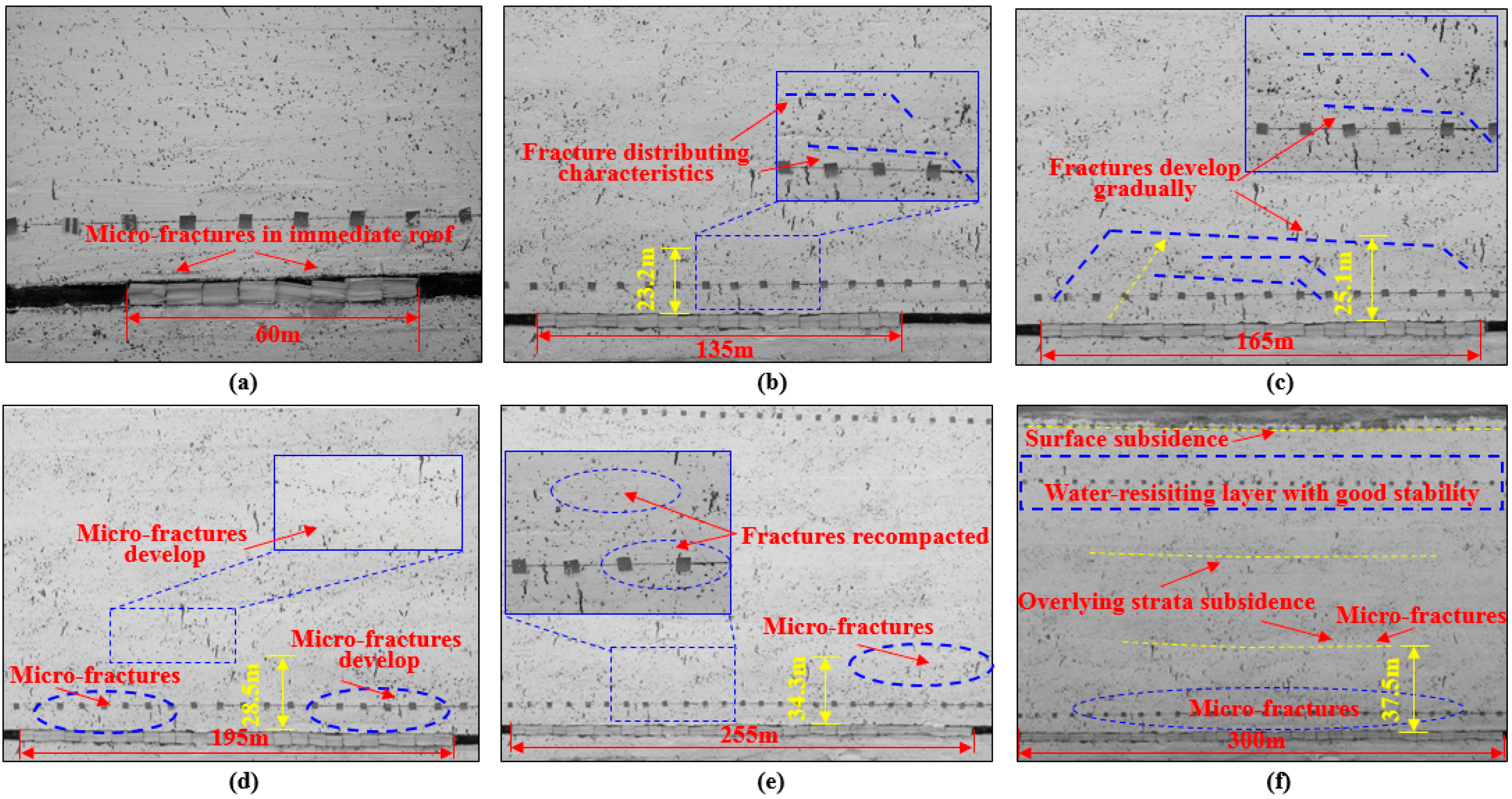
4.2. Simulation Results and Analysis

Figure 9 shows the characteristics of overlying strata movement and the evolution of water-conducting fractures during full caving method coal mining. This corresponds to backfill coal mining with a BMCR of 70% and 90% as shown in Figure 10 and Figure 11, respectively.
The results in Figure 9 show that during full caving coal mining in the physical model, the first caving of the immediate roof will occur with a face excavation of 45 m. As mining advances, the horizontal delamination fractures and vertical fractures develop. The breaking of the main roof happens at a face excavation of 90 m and caving pace of 35 m, as shown in Figure 9c,d. The results also show that the maximum heights of the overlying strata water-conducting fracture were 26.7, 56.7, 90, and 188.7 m at face excavations of 60, 90, 135, and 210 m, respectively. When the face excavation reached 300 m, the vertical and horizontal delamination fractures of the bottom strata are re-compacted under the interaction of overlying strata, and the mining-induced water-conducting fractures are able to develop to the water-resisting layer and surface. The mining-induced overlying strata water-conducting fractures developed in the water-resisting layer and surface at a mining height of 4.5 m, which leads to major geo-environmental hazards at the underground mining face and ground surface eco-environment.
As shown in Figure 10, during the backfill coal mining with a BMCR of 70%, fractures are mainly horizontal delamination fractures and there is a relative decrease in the vertical water-conducting fractures. The maximum height of the overlying strata water-conducting fractures increased from 8.5 to 137.4 m as the face advanced from 60 to 300 m. During this period, the overlying strata fracture evolution laws were visible as fracture development, fracture expansion, and bottom fracture compaction; these were accompanied by subsidence of the entire overlying strata. The results indicate that the water-conducting fractures of the overlying strata were not connected from beneath the ground to the surface during backfill coal mining with a BMCR of 70%, although the fractures had developed to the water-resisting layer. Compared to simulation results obtained for the caving method, backfill coal mining may prevent major geo-environmental hazards in high-intensive coal mining. Therefore, a reasonable BMCR in backfill coal mining is a key factor for coordinated development of coal resource exploitation and environmental protection in China’s western eco-environment frangible area.
During backfill coal mining with a BMCR of 90%, the degree of overlying strata water-conducting fracture development was relatively low, as seen in Figure 11. The maximum heights of the overlying strata water-conducting fractures were 23.2, 25.1, 28.5, and 34.3 m with a face excavation of 135, 165, 195, and 255 m, respectively.
During this period, the fractures were mainly distributed in the bottom of the overlying strata, which is far from the water-resisting layer and surface. When the face excavation reached 300 m, the maximum height of the overlying strata water-conducting fractures was only 37.5 m. To further understand the influence of BMCR on surface deformation and environmental damage, surface deformation (subsidence and horizontal displacement) at BMCRs of 0, 40%, 70%, and 90% were studied using the numerical simulation method, as shown in Figure 12.
The results in Figure 12 show that the maximum subsidence of the surface were 850, 480, 320, and 50 mm at BMCRs of 0, 40% 70%, and 90%, respectively. The maximum horizontal displacements along the X direction were 290, 180, 70, and 22 mm at BMCRs of 0, 40%, 70%, and 90%, respectively. Compared to simulation results obtained for a larger BMCR of backfill coal mining, the caving mining method and a smaller BMCR of backfill coal mining cause significant damage to the surface environment. The details of water-conducting fractures developed with different BMCR is shown in Figure 13a and the vertical displacement along the Z direction and horizontal displacements along the X direction is shown in Figure 13b.
Results indicate that when the BMCR is 90% in the backfill coal mining, the backfill materials can support the overlying strata load effectively. Compared to simulation results obtained for a BMCR of 70% and caving method, the overlying strata water-conducting fractures and surface deformation have been controlled well, which can prevent water flooding disasters and geo-environmental hazards. Therefore, the backfill coal mining method is an optimal strategy for safe and efficient mining in shallow depths with high-intensive mining in China’s western eco-environment frangible area, and a BMCR of 90% is determined to be a reasonable mining scheme for Xiao-Jihan Coal Mine.

5. Analysis and Discussion

The West Development Program and the Silk Road Economic Belt project of China play a vital role in changing the imbalance between eastern and western economic development and modernized construction. In recent years, the western mining area of China has become an important economic hub due to its rich coal resources. With human activity intensifying and increased high-intensive coal mining, geo-environmental hazards have increased in severity. Therefore, methods for realizing the coordinated development of coal resource exploitation and environmental protection in China’s western eco-environment frangible area are significant for both local residents’ lives and economic development. SBM technology, has been successfully applied in more than twenty mining areas in China. This technology has technical advantages in extracting “under three” coal resources (under railways, buildings, and water bodies), handling solid waste, and controlling surface subsidence [24,25]. The technology has mainly been applied in the eastern mining area in recent years, with gangue waste rock used as the main backfilling material. Combing technology with the selection of aeolian sand-based materials as backfilling materials in local mining area is an effective method to solve the geo-environmental hazards discussed above.
In this paper, Xiao-jihan Coal Mine, a typical western mining area of with high-intensive coal mining, was selected as the research area. The compaction properties of aeolian sand-based backfilling materials were tested and analyzed by a self-dependent testing device. The evolution of water-conducting fractures and surface deformation laws with high-intensive mining of different BMCRs was examined through physical simulation and numerical simulation analysis methods. Geo-environmental hazards of the key water-resisting layers’ stability in the Neogene Jingle formation and the Quaternary Lishi formation and surface deformation were assessed and analyzed. This paper presents possible integrated prevention and treatment systems for high-intensive mining. Prevention strategies can be divided into the following main stages (Figure 14): first hazard analysis; then mining-induced strong mining pressure, water-resisting layer fracture, water bursting, surface subsidence and other hazards assessment; next the aeolian sand-based backfill materials are used for underground backfilling at a reasonable BMCR; lastly, the realization of safe and efficient mining in China’s western eco-environment frangible area with geo-environmental hazards prevention and environmental protection.
Compared with traditional mechanized caving mining, the backfill hydraulic support is the key equipment for the success of rapid-backfilling mining. A specially designed backfill support is made up of a front beam, a back beam, six columns, a four-bar linkage, a tamping arm, and a support base. The front beam supports the roof, providing a safe space for operating mining machines, and the back beam provides the space needed for transporting the backfill material, and for dumping and compacting it in the gob. The backfilling scraper conveyor used for transporting the backfilling materials is hung below the back beam [26]. The tamping arm can provide a pressure of 2 MPa to push the backfilling materials in to the gob and compact them to a sufficient density to support the roof effectively. The basic technology and process of backfilling at the working face can be described as follows (Figure 15): After the equipment is installed and debugged, the aeolian sand-based backfill materials are transported and unloaded into the gob at a steady rate (Figure 15a), and then the unloading holes are closed until the materials reach two-thirds of the tamping arm baffle (Figure 15b). After that, the primary and secondary tamping arm will extend to compact the materials (Figure 15c); after a first round of backfilling, the unloading holes will open again to unload and backfill the materials. At this stage, the angle of the tamping arm can be adjusted to backfill the upper area between the roof and the materials (Figure 15d–f). The backfilling process is repeated until a reasonable BMCR is reached that meets the engineering design requirements. After backfilling, the support along with the coal shearer advances to the next backfill circulation.
However, the dynamic mechanism of instability and seepage properties of water-resisting layers and the long-term stability of the surface are important to the material selection and mining operations [27,28]. Therefore, it will be interesting and useful in future research to investigate the seepage-stability of water-resisting layers and measurement of the surface deformation with this method.
In this study, the nature aeolian sand backfilling materials had no effect on the quality of underground water resources, and the mining-induced fractures were well-controlled—there were no interactions between backfill materials and the upper aquifer water, so these materials did not produce groundwater pollution. However, for the mix of backfilling materials containing lime and loess, the interactions between the backfill materials and groundwater could, in some cases, affect the water. This issue is complex and needs more attention; it will be our next topic of research.

6. Conclusions

In this study, a rapid-backfilling technology with water-preservation was proposed as a prevention and control mining solution for major geo-environmental hazards in China’s western high-intensive mining and eco-environment frangible area. By theoretical analysis, experimental testing, physical and numerical simulation, the following conclusions were reached:
(1)
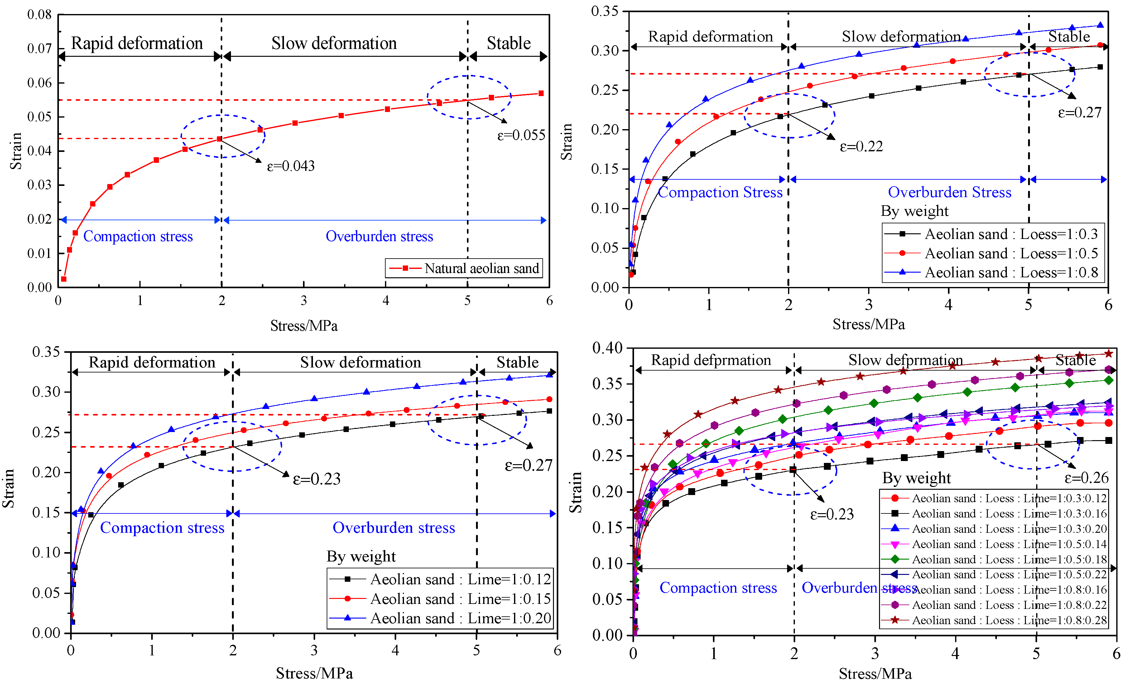
Natural aeolian sand is an optimal backfilling material, the maximum strain of nature aeolian sand is 0.22 and 0.27 with stress 2 MPa and 5 MPa, respectively. The amount of lime and loess can improve the cohesiveness and self-stability of backfilling materials and restrain the compressive property of mix backfilling materials.
(2)
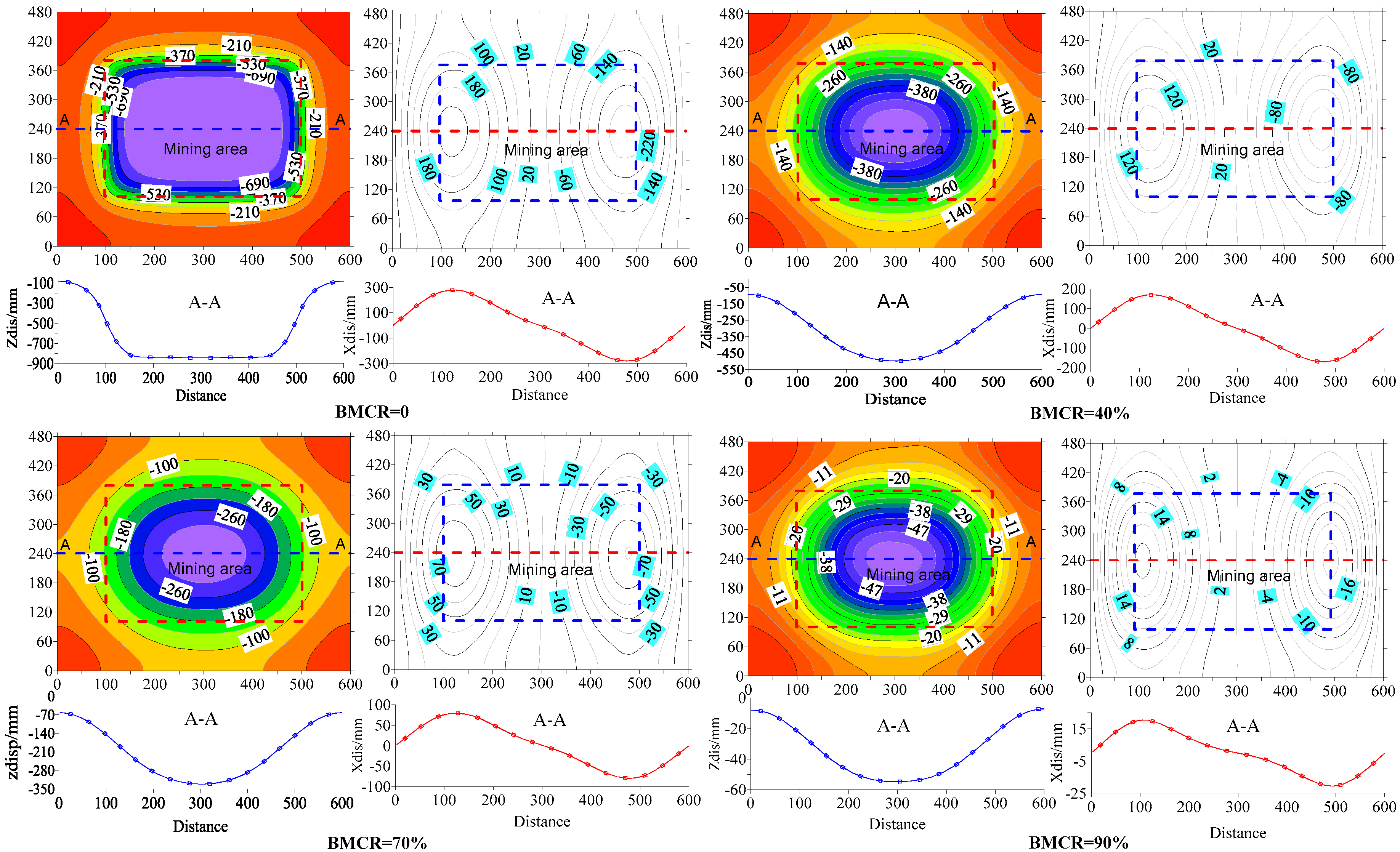
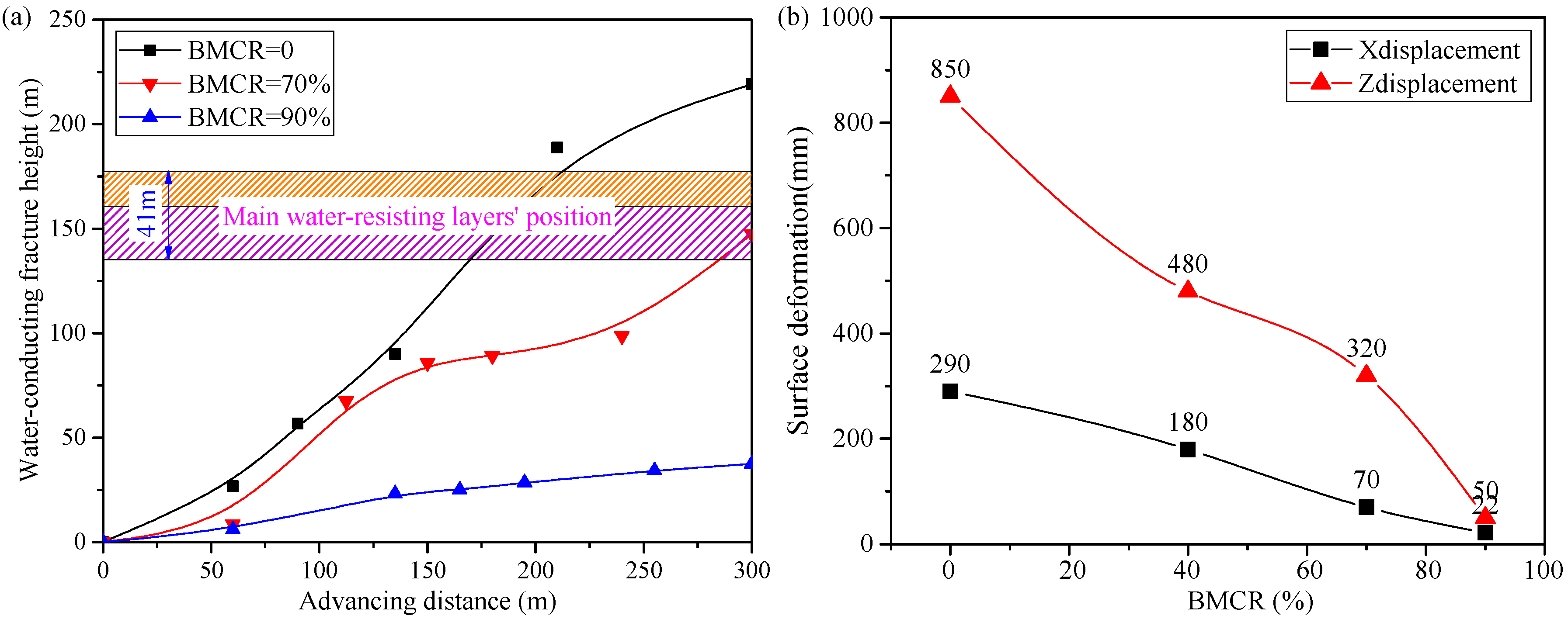
The data from the physical and numerical simulation in Xiao Ji-han Coal Mine shows that the maximum heights of the overlying strata water-conducting fracture was 219.2, 137.4, and 37.5 m with BMCRs of 0, 70%, and 90%, respectively. The maximum subsidence of the surface was 850, 480, 320, and 50 mm with BMCRs of 0, 40%, 70%, and 90%, respectively. The maximum horizontal displacement along the X direction was 290, 180, 70, and 22 mm with BMCRs of 0, 40%, 70%, and 90%. SBM with aeolian sand backfilling materials can effectively control strata movement and deformation, achieving efficient and safe mining.
(3)
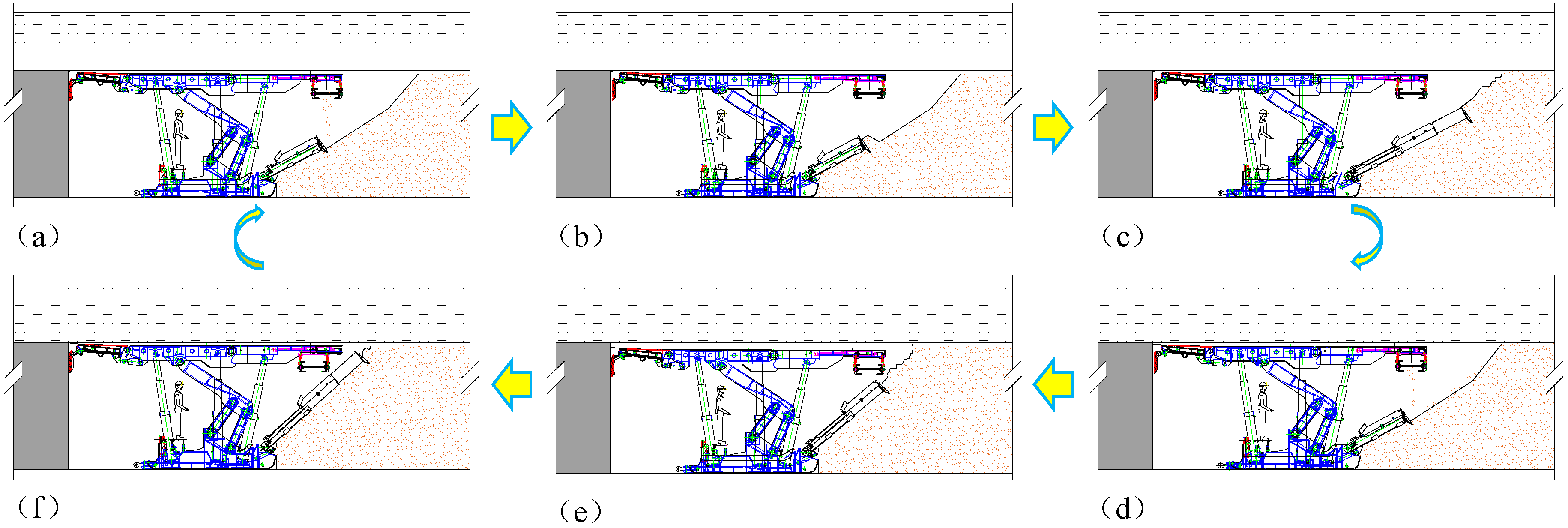
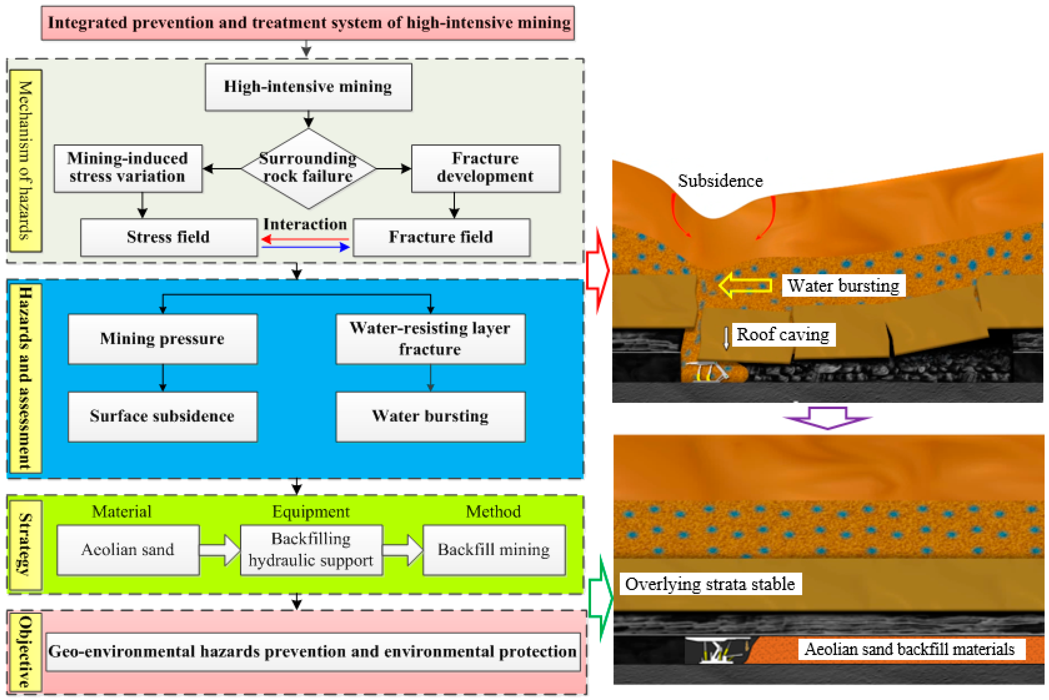
A rapid-backfilling technology and system with water-preserved are established to prevent major geo-environmental hazards in China’s western high-intensive mining and eco-environment frangible area. The key Technology and process of rapid-backfill coal mining with aeolian sand are presented.
(4)
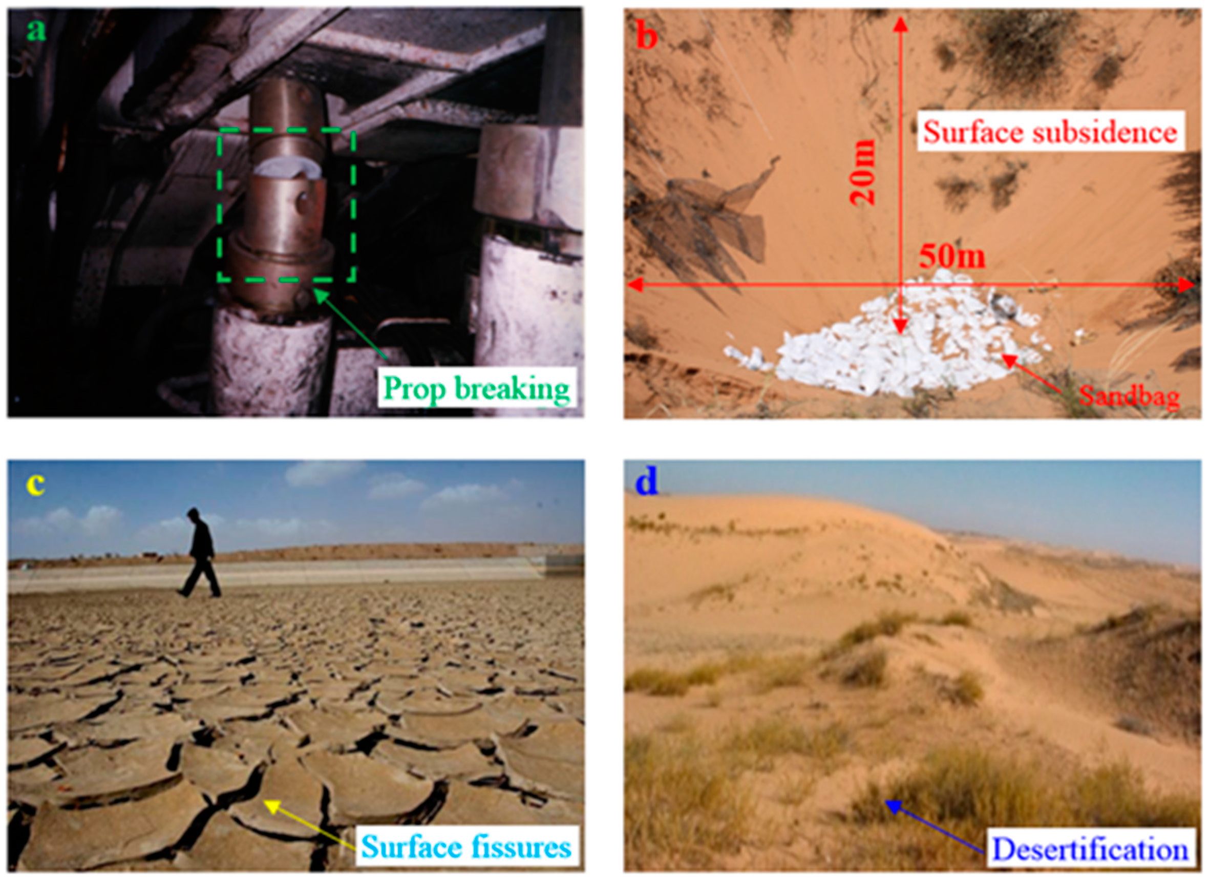
Mining operations in China’s western area are usually associated with strong mining pressure, surface subsidence, soil and water loss, land desertification, and other geo-environmental hazards. SBM technology with aeolian sand-based materials can improve coal resources exploitation and environmental protection and has expansive application foreground, which is helpful for economic and social development in the eco-environment frangible area in western China.

Acknowledgments

This work is supported by the Fundamental Research Funds for the Central Universities (2017BSCXB46). The authors gratefully acknowledge the financial support from the organization mentioned above.

Author Contributions

Jixiong Zhang proposed the innovative points and conceived; Qiang Sun established and solved the numerical and physical model; Qiang Zhang and Xu Zhao analyzed the data; Qiang Sun and Jixiong Zhang wrote the paper; Xu Zhao revised the paper.

Conflicts of Interest

The authors declare no conflict of interest.

References

  1. Li, P.Y. Groundwater quality in western China: Challenges and paths forward for groundwater quality research in western China. Expo. Health 2016, 8, 305–310. [Google Scholar] [CrossRef]
  2. Li, P.Y.; Qian, H.; Howard, K.W.F.; Wu, J.H. Building a new and sustainable “silk road economic belt”. Environ. Earth Sci. 2015, 74, 7267–7270. [Google Scholar] [CrossRef]
  3. Wang, J.H. Key technology for fully-mechanized top coal caving with large mining height in extra-thick coal seam. J. China Coal Soc. 2013, 38, 2089–2098. [Google Scholar]
  4. Hu, S.; Bi, H.P.; Li, X.H.; Yang, C.H. Environmental evaluation for sustainable development of coal mining in Qijiang, Western China. Int. J. Coal Geol. 2010, 81, 163–168. [Google Scholar]
  5. Yang, D.J.; Bian, Z.F.; Lei, S.G. Impact on soil physical qualities by the subsidence of coal mining: A case study in Western China. Environ. Earth Sci. 2016, 75, 1–14. [Google Scholar]
  6. Zhang, C.; Zhong, L.J.; Fu, X.T.; Zhao, Z.N. Managing scarce water resources in China’s coal power industry. Environ. Manag. 2016, 57, 1188–1203. [Google Scholar] [CrossRef] [PubMed]
  7. Miao, X.X.; Zhang, J.X.; Guo, G.L. Study on waste-filling method and technology in fully-mechanized coal mining. J. China Coal. Soc. 2010, 35, 1–6. [Google Scholar]
  8. Bian, Z.F.; Miao, X.X.; Lei, S.G.; Chen, S.E.; Wang, W.F.; Struthers, S. The challenges of reusing mining and mineral-processing wastes. Science 2012, 337, 702–703. [Google Scholar] [CrossRef] [PubMed]
  9. Zhang, J.X.; An, B.F.; Ju, F.; Jiang, H.Q.; Wu, Q. Influence factors of solid material particles motion in the feeding system of fully mechanized coal mining and backfilling. J. Min. Saf. Eng. 2012, 3, 312–316. [Google Scholar]
  10. Morteza, S. A review of underground mine backfilling methods with emphasis on cemented paste backfill. Electron. J. Geotech. Eng. 2015, 20, 5182–5208. [Google Scholar]
  11. Huang, Y.L.; Zhang, J.X.; Zhang, Q.; Nie, S.J. Backfilling technology of substituting waste and fly ash for coal underground. Environ. Eng. Manag. J. 2011, 10, 769–775. [Google Scholar]
  12. Zhang, J.X.; Zhang, Q.; Sun, Q.; Gao, R.; Germain, D.; Abro, S. Surface subsidence control theory and application to backfill coal mining technology. Environ. Earth Sci. 2015, 74, 1439–1448. [Google Scholar] [CrossRef]
  13. Sun, Q.; Zhang, J.X.; Ju, F.; Li, L.Y.; Zhao, X. Research and application of schemes for constructing concrete pillars in large section finishing cut in backfill coal mining. Int. J. Min. Sci. Technol. 2015, 25, 915–920. [Google Scholar] [CrossRef]
  14. Jiang, H.Q.; Miao, X.X.; Zhang, J.X.; Liu, S.W. Gateside packwall design in solid backfill mining-a case study. Int. J. Min. Sci. Technol. 2016, 26, 261–265. [Google Scholar] [CrossRef]
  15. Huang, Y.; Li, J.M.; Song, T.Q.; Kong, G.Q.; Li, M. Analysis on filling ratio and shield supporting pressure for overburden movement control in coal mining with compacted backfilling. Energies 2016, 10, 31. [Google Scholar] [CrossRef]
  16. Zhou, N.; Han, X.L.; Zhang, J.X.; Li, M. Compressive deformation and energy dissipation of crushed coal gangue. Powder Technol. 2016, 297, 220–228. [Google Scholar] [CrossRef]
  17. Li, M.; Zhang, J.X.; Zhou, N.; Huang, Y.L. Effect of particle size on the energy evolution of crushed waste rock in coal mines. Rock Mech. Rock Eng. 2016, 50, 1347–1354. [Google Scholar] [CrossRef]
  18. Zhang, J.X.; Sun, Q.; Zhou, N.; Jiang, H.Q.; Germain, D. Research and application of roadway backfill coal mining technology in western coal mining area. Arab. J. Geosci. 2016, 9, 558. [Google Scholar] [CrossRef]
  19. Sun, Q.; Zhang, J.X.; Yin, W.; Zhou, N.; Liu, Y. Study of stability of surrounding rock and characteristic of overburden strata movement with longwall roadway backfill coal mining. J. China Coal Soc. 2017, 48, 404–412. [Google Scholar]
  20. Huang, Y.L.; Zhang, J.X.; An, B.F.; Zhang, Q. Overlying strata movement law in fully mechanized coal mining and backfilling longwall face by similar physical simulation. J. Min. Sci. 2011, 47, 618–627. [Google Scholar]
  21. Wang, F.T.; Tu, S.H.; Zhang, C.; Zhang, Y.W.; Bai, Q.S. Evolution mechanism of water-flowing zones and control technology for longwall mining in shallow coal seams beneath gully topography. Environ. Earth Sci. 2016, 75, 1309. [Google Scholar] [CrossRef]
  22. Ma, D.; Bai, H.; Wang, Y. Mechanical behavior of a coal seam penetrated by a karst collapse pillar: Mining-induced groundwater inrush risk. Nat. Hazards 2015, 75, 2137–2151. [Google Scholar] [CrossRef]
  23. Sun, Q.; Zhang, J.X.; Zhang, Q.; Yin, W.; Germain, D. A protective seam with nearly whole rock mining technology for controlling coal and gas outburst hazards: A case study. Nat. Hazards 2016, 84, 1793–1806. [Google Scholar] [CrossRef]
  24. Zhang, J.X.; Zhang, Q.; Sam, S.A.J.S.; Miao, X.X.; Guo, S.; Sun, Q. Green coal mining technique integrating mining-dressing-gas draining-backfilling-mining. Int. J. Min. Sci. Technol. 2017, 27, 17–27. [Google Scholar] [CrossRef]
  25. Zhang, J.X.; Jiang, H.Q.; Deng, X.J.; Ju, F. Prediction of the height of the water-conducting zone above the mined panel in solid backfill mining. Mine Water Environ. 2014, 33, 317–326. [Google Scholar] [CrossRef]
  26. Zhang, J.X.; Li, B.Y.; Zhou, N.; Zhang, Q. Application of solid backfilling to reduce hard-roof caving and longwall coal face burst potential. Int. J. Rock Mech. Min. Sci. 2016, 88, 197–205. [Google Scholar] [CrossRef]
  27. Jiang, Q.; Ye, Z.; Zhou, C. A numerical procedure for transient free surface seepage through fracture networks. J. Hydrol. 2014, 519, 881–891. [Google Scholar] [CrossRef]
  28. Lv, X.; Wang, Z.; Wang, J. Seepage–damage coupling study of the stability of water-filled dump slope. Eng. Anal. Bound. Elem. 2014, 42, 77–83. [Google Scholar] [CrossRef]
Figure 1. Geo-environmental hazards caused by coal mining. (a) Strong mining pressure; (b) Surface subsidence; (c) Soil and water loss; (d) Land desertification.
Energies 10 00786 g001
Figure 2. Longwall panel layout of Xiao-jihan Coal Mine.
Energies 10 00786 g002
Figure 3. Stratigraphic column and section of No. 11 panel and No. 12 panel.
Energies 10 00786 g003
Figure 4. Water inrush and pumping-drainage system with high-intensive mining on site.
Energies 10 00786 g004
Figure 5. Experimental equipment and backfill materials. (a) Equipment; (b) Materials.
Energies 10 00786 g005
Figure 6. Stress-strain curves of aeolian sand-based materials.
Energies 10 00786 g006
Figure 7. Physical simulation: (a) selection of similar backfill materials; (b) measurement system and software.
Energies 10 00786 g007
Figure 8. Sketch of the FLAC3D mesh for numerical simulation.
Energies 10 00786 g008
Figure 9. Development characteristics of overlying strata water-conducting fractures with caving method. (a) face advance of 45 m; (b) face advance of 60 m; (c) face advance of 90 m; (d) face advance of 135 m; (e) face advance of 210 m; (f) face advance of 300 m.
Energies 10 00786 g009
Figure 10. Development characteristics of overlying strata water-conducting fractures with BMCR of 70%. (a) face advance of 60 m; (b) face advance of 112.5 m; (c) face advance of 150 m; (d) face advance of 180 m; (e) face advance of 240 m; (f) face advance of 300 m.
Energies 10 00786 g010
Figure 11. Development characteristics of overlying strata water-conducting fractures with BMCR of 90%. (a) face advance of 60 m; (b) face advance of 112.5 m; (c) face advance of 150 m; (d) face advance of 180 m; (e) face advance of 240 m; (f) face advance of 300 m.
Energies 10 00786 g011
Figure 12. Development characteristics of surface deformation with BMCRs of 0, 40%, 70% and 90%.
Energies 10 00786 g012
Figure 13. Fracture evolution and surface deformation with high-intensive mining.
Energies 10 00786 g013
Figure 14. Integrated prevention and treatment system of high-intensive mining.
Energies 10 00786 g014
Figure 15. Technology and process of rapid-backfill coal mining with aeolian sand.
Energies 10 00786 g015
Table 1. The testing of the compacting properties of aeolian-sand materials.
SchemeNo.Material Ratio (By Weight)Maximum Strain (0–2 Mpa)Maximum Strain (2–5 MPa)
Aeolian sandI1:00.0430.055
Aeolian sand: LoessI1:0.30.220.27
II1:0.50.250.30
III1:0.80.2750.325
Aeolian sand: LimeI1:0.120.230.27
II1:0.150.250.28
III1:0.200.2750.32
Aeolian sand: Loess: LimeI1:0.3:0.120.250.29
II1:0.3:0.160.230.26
III1:0.3:0.200.260.30
IV1:0.5:0.140.260.30
V1:0.5:0.180.300.35
VI1:0.5:0.220.280.32
VI1:0.8:0.160.280.32
VII1:0.8:0.220.330.36
IX1:0.8:0.280.350.39
Table 2. Simulation parameters of the test model.
No.LithologicThickness (m)Bulk Modulus (GPa)Shear Modulus (GPa)Cohesion (MPa)Tensile Strength (MPa)Internal Friction Angle (°)Density (kg/m3)
1Surface layer250.080.050.20.05161670
2Sandy soil170.120.080.50.1181800
3Sandy clay150.50.30.80.5182200
4Clay and mudstone261.81.21.20.7222300
5Medium sandstone7.51.51.01.40.9222500
6Mudstone212.21.81.80.7262250
7Fine Sandstone102.42.02.21.2252400
8Medium sandstone171.51.01.40.9222500
9Fine Sandstone62.42.02.21.2252400
10Sandstone312.82.22.51.5282550
11Mudstone122.21.81.80.7262250
12Medium sandstone251.51.01.40.9222500
13Fine Sandstone62.42.02.21.2252400
14Coal seam4.52.52.32.51.5281400
15Mudstone42.21.81.80.7262250
16Siltstone132.82.22.41.1302400

