
Performance of an Energy Efficient Low Power Stepper Converter

Institute of Machine Design and Hydraulic Drives, Johannes Kepler University Linz, Altenberger Strasse 69, 4040 Linz, Austria
*
Author to whom correspondence should be addressed.
Energies 2017, 10(4), 445; https://doi.org/10.3390/en10040445
Submission received: 21 February 2017
/
Revised: 17 March 2017
/
Accepted: 22 March 2017
/
Published: 28 March 2017
(This article belongs to the Special Issue Energy Efficiency and Controllability of Fluid Power Systems)
Abstract
:This paper presents the development of an energy efficient low power stepper converter. A prototype with a hydraulic output power of ≈600 W was designed, manufactured, investigated and improved. The converter consists of a hydraulic cylinder piston unit controlled by a fast switching valve to displace a defined fluid quantum by the limited forward stroke of the piston in its cylinder. The displaced fluid generates a precise, incremental motion of a load cylinder which should be controlled. Energy saving is achieved by storing the pressure surplus intermediately in the kinetic energy of the piston to displace a part of the fluid quantum without hydraulic energy from the supply line. Energy recuperation can be done in a similar way. Simulations and experiments showed two main efficiency improvement measures of the first converter prototype. The weak points were the commercially available check valves and the used guidance system for the pistons. The second part of the paper reports about the development of a fast check valve and of a combined hydrostatic hydrodynamic bearing system based on the elastic deformation of plastics. The theoretical and experimental results show a significant improvement of the energy efficiency, the potential of this drive technology and further improvement potential. Expressed in terms of numbers an energy efficiency increase compared to a resistance control up to 30% and a maximum recuperation energy efficiency over 60% were measured.
1. Introduction
Reduction of energy consumption is an important topic for many modern machine systems. However, the saving of energy is often traded-off by several other requirements, like robustness, low investment costs, higher precision, e.g., to improve product quality, and higher productivity. Fluid power drives, in particular hydraulic drives, are often not the main drives of a machine, but provide auxiliary actuation, e.g., for tool positioning. In such cases, the net energy actually spent for such actuation is only a small share of the total energy consumed by the machine and, unfortunately, often also a small share of the energy consumed by this particular actuator. Frequent scenarios leading to such an unfavorable energy use are hydraulic positioning or force control actuators using servo valves with small or only occasional output motions. Then, the leakages at the servo valve’s metering edges and its pilot stage might consume a multiple of the hydraulic energy used by the actuated process. Krieger [1] analyses the hydraulic power consumption of hot rolling mills and finds that of approximately 100 kilowatts average hydraulic power supplied only 12% are used for the diverse processes, like gap control and looper positioning, and about 80% are due to leakage losses and pilot stage consumption. Only the remaining 8% are due to pressure losses at the metering edges which constitute the systematic loss due to resistance control. This example suggests, trying to find specific solutions for each drive or actuator taking its specific operation scenario and requirements into account. In many cases, this offers a much higher energy saving potential than marginal efficiency improvements of standard drive and actuation systems.
In this paper a study of a so called stepper converter is presented. From a functional viewpoint this system is a combination of a stepper drive and a switching converter. Stepper drives create defined motion steps which can potentially save costly position sensors with all the necessary cabling and connectors, if the steps are done with sufficient accuracy. If this simple control functionality can be combined with low average energy consumption in a specific application, a contribution to energy saving in general is made. Energy saving for such auxiliary drives must often come quasi “through the backdoors”, i.e., by offering other advantages, like, for instance, robustness, low cost, or ease of control. Stepper drives, as presented in this paper, are intended for application where traditionally hydraulic servo drives are used. The expected advantages are not only energy savings discussed above but also higher robustness against oil contamination and, as a consequence of lower energy consumption, smaller hydraulic power supply units. The latter not only has cost and compactness benefits but may allow installing supply units close to the actuator and saving in this way piping and hosing expenses.
Stepper drives are the most obvious way for sensorless position control. The electric stepper motor is frequently used in low power applications and provoked several trials to invent stepper drives in fluid power. Different concepts of hydraulic and pneumatic stepper drives were proposed, investigated and patented in the last three decades. A simple hydraulic stepper drive was presented by Pfeifer and Schmitt in [2]. A hydraulic cylinder moves between its two end-stops and in one direction the motion is transferred to a piston rod by a clamping unit. In this direction the piston performs a stepping motion. Zenny [3] investigated a linear electrohydraulic pulse drive actuator which consists of an electrical stepping motor, a rotary input-rotary feedback servo valve and a linear cylindrical actuator with an internal ball-screw which is used only as mechanical feedback for the servo valve.
Different concepts of hydraulic or pneumatic stepping actuators for choke valves in various designs are presented by Advanced Actuators [4], Introl [5] and Cove [6]. Most of the choke valves use a piston-pawl arrangement to convert the linear motion of the hydraulic or pneumatic cylinders to a rotary motion for actuation the closing and opening mechanism. Such stepping actuators have a maximum speed of 120 steps per minute and typically need 100–200 steps to perform the full stroke. An additional position sensor is used for position feedback and for safety reasons.
An obvious idea in terms of sensorless position control of hydraulic actuators is to use a speed variable motor which drives a constant displacement pump [7,8]. However, this approach has a quite limited position accuracy because of the pump leakage and the fluid compressibility. The achievable position error is in the range of few percent what is sufficient for several applications, e.g., the load lifting in a fork lift truck by Minav et al. [7].
The authors investigated a high accuracy linear hydraulic stepper drive for sensorless position tasks in hydraulics [9] based on the patent [10]. The practicability of the sensorless concept was evaluated for a cylinder drive as depicted in Figure 1. The drive performs steps with an accuracy and repeatability of .
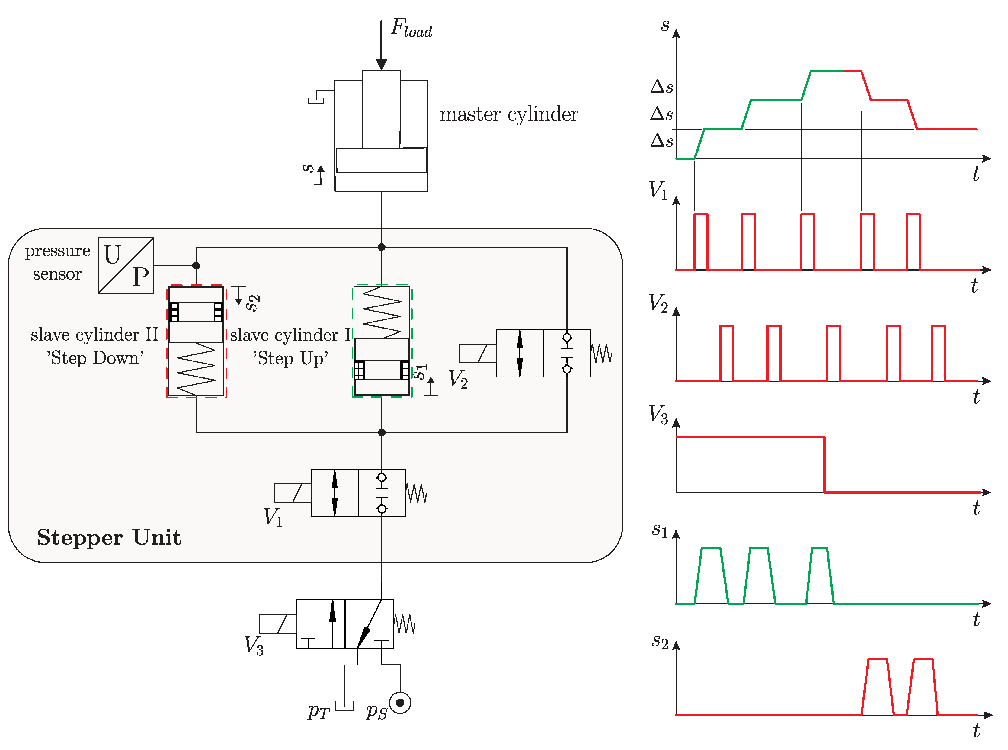
The drive consists of a hydraulic cylinder which is controlled by a stepper unit. The hydraulic scheme and the timing diagram are depicted in Figure 2. For a fully operable hydraulic drive two slave cylinders are necessary, one for extension (‘Step Up’) and one for retraction (‘Step Down’). Each slave cylinder consists of a slave piston with a sealing to avoid leakage and a return spring. The two 2/2-way switching valves ( and ) connect the cylinder chambers alternately to the supply pressure or tank line or to the opposite chambers. With the 3/2-way switching valve the operation mode (‘Step Up’ and ‘Step Down’) can be chosen. For a proper function of the Stepper Unit the switching valves and have to be leakproof. This can be achieved by proper seat type valves. With a computation model the accuracy of the drive can be increased further.
Hydraulic switching control, in particular switching converters, can improve energy efficiency compared to resistance control and can also recuperate energy in a generic manner. Switching converters require inherently to utilize some inertance or inductivity effects. If fluid is the inertance element its compressibility and viscosity deteriorate the converter performance. On the contrary, rigid bodies as inertance elements, as is the case in the so called hydraulic resonance converter investigated by Scheidl and Riha [11], give more freedom in the adjustment of inertance, capacitance and friction. An overview of switching control and the objectives, concepts, challenges and potential applications can be found, e.g., in Scheidl et al. [12]. The idea of using inertia effects and so called free-wheeling valves for energy saving was published by Gall and Senn in [13].
The converter presented in this paper is a special switching converter with the possibility of sensorless position control. In previous publications [14,15,16] the fundamental performance, mechanical design of the prototype and experiments were presented. It was concluded that the energy efficiency can be drastically increased by using a better piston sealing and guidance system and faster check valves.
This paper reports the converter improvement. For this a fast switching plate type check valve and a combined hydrostatic hydrodynamic bearing based on elastic deformations were developed and investigated. These results are not only helpful for the stepping converter but also for other switching converters, recently often entitled switched inertance systems, see for instance Pan et al. [17].
The article is organized as follows. In Section 2 the stepper converter concept, its mechanical design and some performance results are presented. Section 3 addresses the investigations for improving two components which were found being critical for loss reduction, check valves and the friction of the piston. Experimental results of a prototype with the improved components are given in Section 4. Section 5 sums up and looks ahead to future work.
2. Hydraulic Stepper Converter
The basic working principle is fairly simple and requires a few components only. Nonetheless, the physical limitations of the currently available key components, e.g., seat valves which show a dynamic leakage, and parasitic effects like hydraulic capacitances in the ducts or wave propagation may pose some problems which have to be overcome by a proper design and component selection.
2.1. Operation Principle
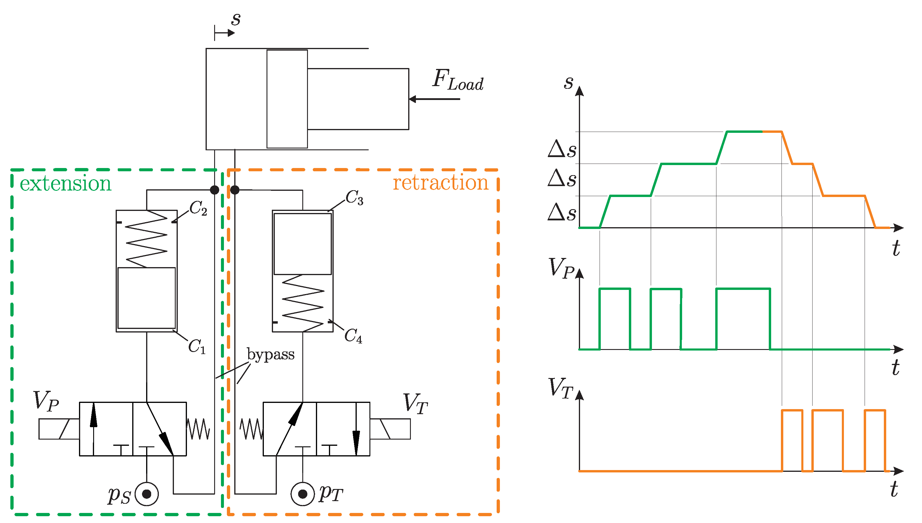
In order to understand the basic working principle the Hydraulic Stepper Drive (HSD) without energy saving capabilities is briefly described first. A schematic of a hydraulic plunger cylinder with two HSDs acting against a process force is shown in Figure 3. Of the two HSDs one is needed for extension and one for retraction of the hydraulic plunger cylinder. The essential components of a HSD are one active 3/2 way fast- switching valve and a cylinder with a piston and a return spring. The piston divides the cylinder in two hydraulic chambers, and , respectively. The HSD exploits the simple fact that an end to end motion of a piston within its cylinder is always exact, a priori known and can generate a precise amount of displaced fluid.
The switching valve connects the cylinder chamber alternately to the pressure line or to the opposite chamber according to the timing diagram depicted in Figure 3.
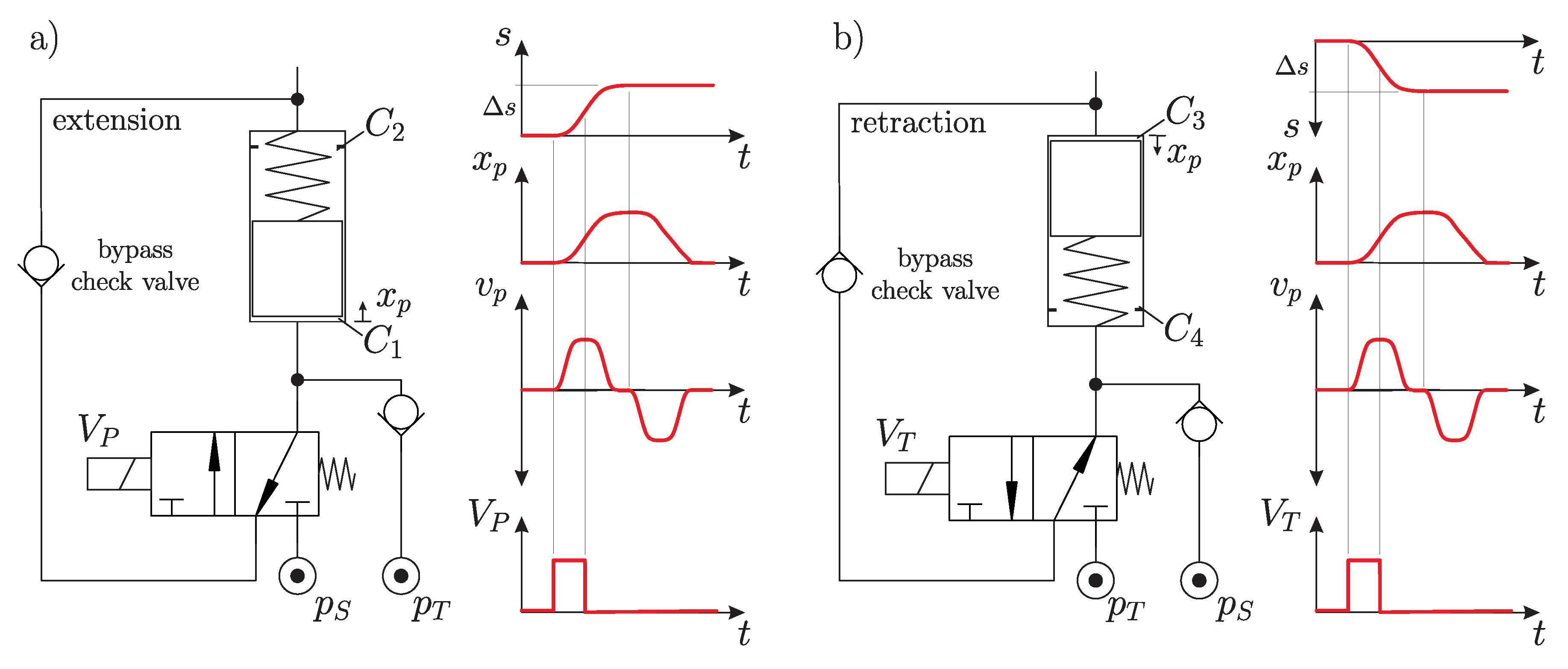
The piston starts at its bottom position (Figure 4a). Switching the valve on, makes the piston move due to the difference of system and actuator pressure (Figure 4b). During the upward movement of the piston, oil is shifted to the consumer line and—in the ideal case—the hydraulic plunger cylinder performs a single position step with the consistent step-size (assuming the hydraulic fluid is incompressible). In the energy-efficient operation mode of the HSD, is switched off before the piston has reached the top position (Figure 4c). For this operation mode additional check valves are necessary (compare Figure 3 to Figure 4) and the piston needs to have some inertia to build-up kinetic energy from the surplus of system pressure when is on. This energy is fed to the consumer in the phase when is off and the piston travels to its end-stop. One of the check valves is located in the bypass of the HSD. When is off the moving piston sucks oil from the tank line into chamber . To avoid cavitation during this suction phase the tank system has to be pre-pressurized.
Due to the mechanically limited stroke of the piston, the delivered fluid quantum is exactly known. When the piston has reached its topmost position (Figure 4d), the return spring moves the piston back to the lowest position and the oil is shifted through the bypass or the bypass check valve from chamber to chamber (Figure 4e). If the piston is back in the lowest position the next cycle can be started at any time (Figure 4a). In this way, a pulse frequency control can be realized. Identical flow pulses are sent or taken from the consumer in any timing sequence. Higher frequency increases the actuator speed. Such pulsed control is likely to provoke unwanted oscillation. They can be counteracted by a proper double pulse techniques as shown by Gradl and Scheidl [18], by passive hydraulic filtering investigated by Haas et al. [19,20], or by a phase shifted operation of several HSD’s connected on one cylinder drive in parallel, as has been demonstrated for the hydraulic buck converter by Kogler [21].
The stepwise retraction of the hydraulic plunger cylinder is done by a second HSD in reverse mode (HSDr) as depicted in Figure 3. Starting at the topmost position the piston is accelerated by the difference of load and tank pressure when is switched on. During the downward movement of the piston oil is shifted from consumer line to the piston chamber . Also in this case the piston displaces a fixed fluid quantum out of the cylinder to the supply lines, hence the hydraulic plunger cylinder performs a precise change of position. When the piston has reached its lowest position and the valve is switched back, the return spring moves the piston back to the topmost position and the oil is shifted through the bypass or the bypass check valve (Figure 5) from chamber to chamber .
In case of an pushing load force it is possible to recuperate energy during retraction of the hydraulic cylinder. The basic concept is nearly the same as of the HSD for outward motion, only the direction of the check valves, the position of the springs and the arrangement of the system- and tank pressure ports are changed as illustrated in Figure 5.
In the energy recuperation mode (Figure 5b), the valve switches to the initial position before the piston has reached the lowest position of the cylinder. The momentum keeps the piston moving on and shifts oil through the check valve to the system pressure line.
2.2. Mechanical Design
The converter was studied by a simple mathematical model and its system parameters were obtained by a design optimization procedure. The results were published in [14] and are summarized in the following paragraphs.
To keep the losses in the valve low, fast valves with a sufficient high flow rate are necessary. The size of the valve influences the pressure drop and the throttling losses in the open position. The switching time limits the feasible maximum switching frequency, which is important to obtain a reasonably sized system and should be above .
Not only a fast switching valve is important for high energy efficiency, but also fast check valves with a sufficient nominal flow rate. For the specific HSD prototype a nominal flow rate of at pressure drop is a satisfactory value. Commercially available check valves feature a large stroke of the opening element (e.g., plate or ball) to reach the high flow rates. Furthermore, the spring rate of the return spring is low (e.g., ) and the mass of the plate relatively high (e.g., ), what leads to a slow mechanical response, reasonably characterised by the natural frequency of the oscillator formed by the plate mass and return spring. This low frequency causes a slow closing of the valve which may give some backflow, e.g., from camber to tank line, when pressure changes sign quickly.
Parasitic effects are unwanted but unavoidable physical effects in a hydraulic element or system; for instance, a bore in a block is no ideal line but has some hydraulic impedance in form of an inductance, capacitance, or resistance. Parasitic effects deteriorate real system performance compared to the basic ideal working principle. Lowering these effects to insignificant levels is generally a high challenge in the design of fast switching hydraulic systems. Particularly, charge losses due to hydraulic capacitances have to be taken into account because they can reduce the energy efficiency drastically.
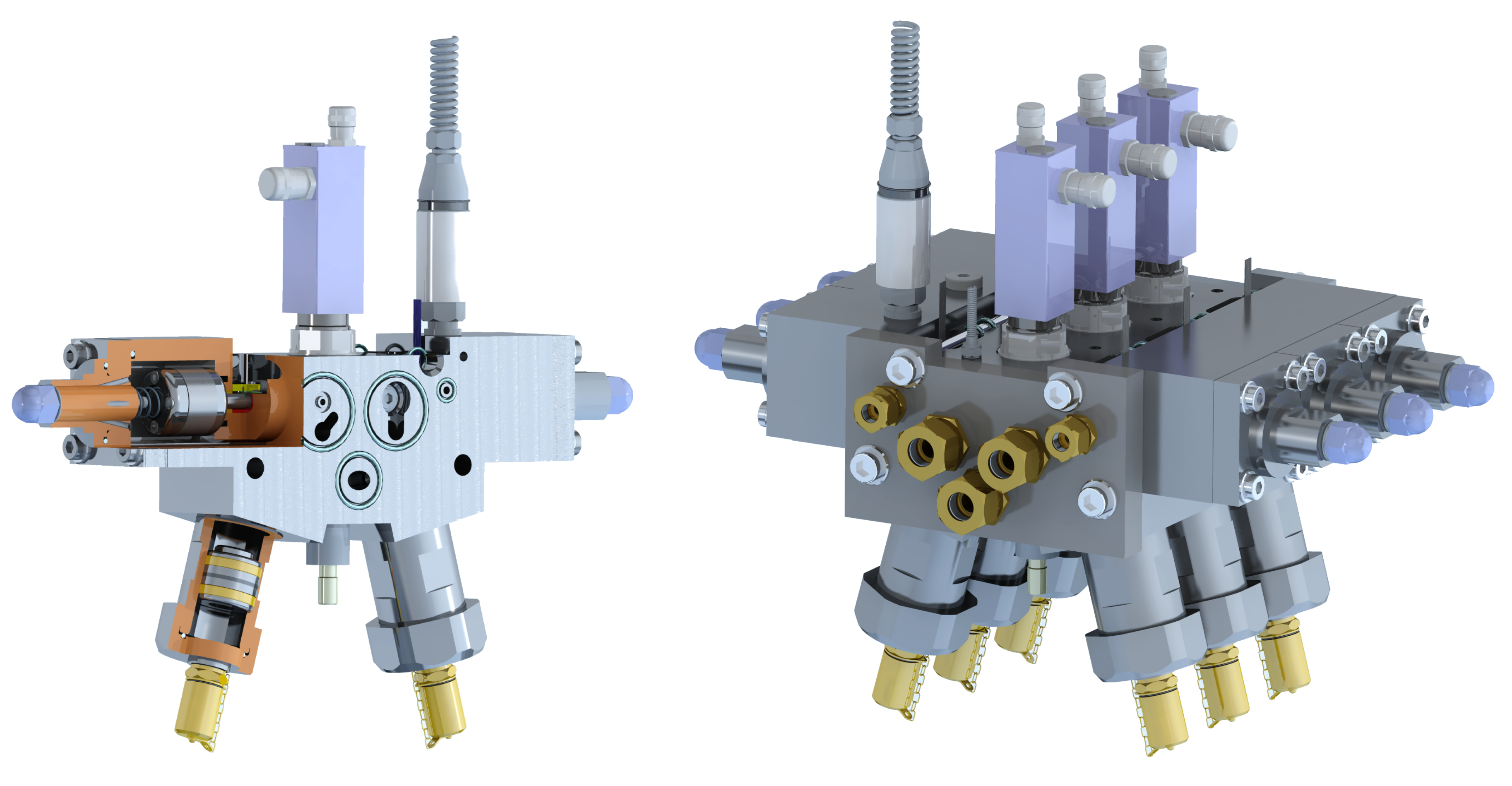
To keep the parasitic effects as small as possible several requirements have to be considered in the hydraulic block design. The block has to incorporate one switching valve, two check valves, a piston with sufficient inertia (realized by a bulky mass) and decoupling attenuators. The mechanical design is depicted in Figure 6. For a sound experimental analysis of the prototypal HSD several additional sensors were installed. Sensors for the piston’s positions, the switching valve’s spool position and the pressure at each port are required for an elaborate experimental analysis of the prototype HSD.
The developed block design of the HSD allows a compact arrangement of multiple HSDs by stacking. In this block design the active switching valve is mounted from the top. To reach a high switching frequency, the spool type fast switching valve FSVi from the company LCM was chosen. The FSVi has a hydraulic switching time below 1 ms and a nominal flow rate of 10 L/min @ 5 bar pressure drop (more details of this valve can be found in Ploeckinger et al. [22]).
The three through bores are the supply, the tank and the consumer line. Two pistons are located opposite to each other to annihilate their oscillatory inertia forces, which otherwise might provoke substantial oscillations of the HSD and a corresponding acoustic noise.
As mentioned above, the block of the HSD and the HSDr are identical. Only the direction of the check valves and the connection of the supply lines change. Due to the symmetric drilling pattern the connections can be changed by a back-to-front assembly. For practical use the mechanical design can be greatly reduced and only one pressure sensor at the consumer line is required.
2.3. Theoretic Energy Efficiency
The actual energy efficiency of the converter for a certain operation point is defined as
with the average flow rates , and and the constant pressures , and of the two supply lines and the consumer port, respectively.
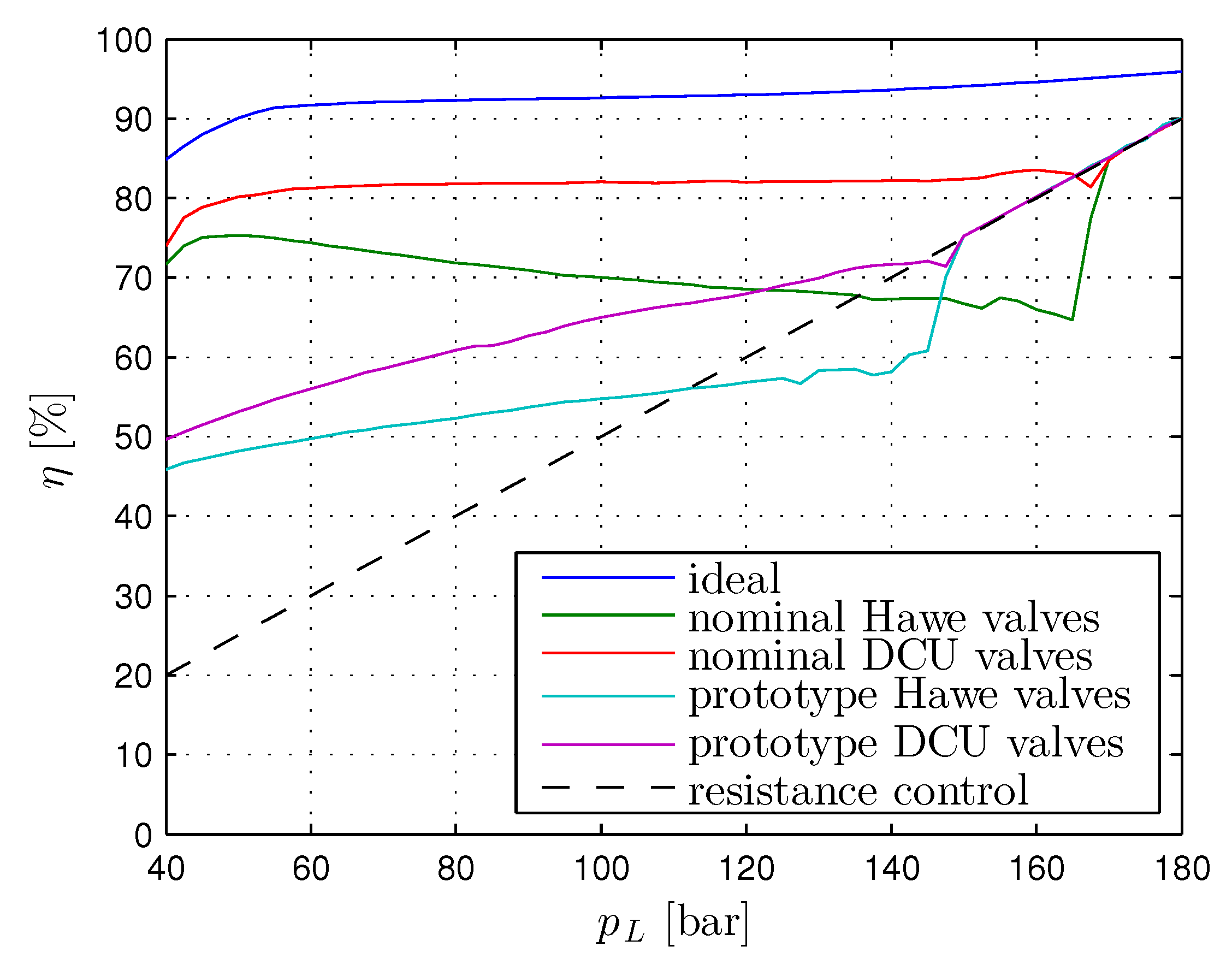
The energy efficiencies for five cases of the HSD are illustrated in Figure 7. It is distinguished between different parameter sets and check valves according to following list:
- ideal: infinite fast valves without parasitic effects and no friction
- nominal: nominal parameter values for the given design
- prototype: identified parameter values for the manufactured prototype HSD 001
- Hawe valves: commercial available check valves (RC1 and RC2 from the company Hawe)
- DCU valves: plate type check valve developed by the authors (see Section 3.1)
It is obvious that the ideal case with infinitely fast valves, without parasitic effects and no friction, has the highest energy efficiency. According to Figure 7 the energy efficiency of the prototype is not as good as predicted with the nominal parameter values. The reason is the higher friction between piston and sleeve. This results in higher energy dissipation. Furthermore, the energy efficiency can be increased by using faster check valves like those developed by the authors and presented in detail in Section 3.1.
The contribution of the different loss sources can be identified by simulations of the HSD. In Figure 8 the loss distributions for the same five cases, as discussed in the previous section, are shown. In the ideal case (top left figure) the major part of the losses are throttling losses through the switching valve and the impact losses of the piston at the end stops (kinetic energy at the end stops).
For the nominal designs (top middle and top right figure) the throttling losses (product of difference pressure over the valve and the flow rate Q) of all valves are higher. In fact, larger dead volumes cause also higher throttling losses, because they must be charged and discharged at every switching cycle. It can be seen that a faster check valve, which reduces the backflow, can minimize the losses.
For the prototype (bottom left and bottom middle figure) the major part of the losses are generated by the friction in the piston sealing gaps. It is obvious that the reduction of the friction (in consequence the reduction of the spring pre-load) will drastically increase the energy efficiency of the HSD. But also a faster check valve increases the energy efficiency in a wide range.
3. Component Development
The simulation results according to the measurements showed that the energy efficiency can be improved by a faster check valve and a improved bearing and sealing system of the piston. In this section the developed check valve and bearing system with the corresponding simulation models are presented.
3.1. Fast Plate Type Check Valve
Many researchers in the field of fast switching hydraulic systems, particularly in high frequency oscillation pumps and hydraulic converters, classified the valves as bottleneck of these systems (Leati [23] and Kogler [24]). Various problems like cavitation, overpressure peaks and cross-flow can occur if the valve is not fast enough in relation to the movement of the piston.
Such fast check valves are not commercially available. Thus, a fast check valve (DCU) had to be developed for the HSD. A fast dynamic response of the valve is required to minimize the overpressure, back flow and cavitation effects. The technical needs on the check valve design can be summarized as:
- a small moving mass (plate and equivalent spring mass) in conjunction with a stiff spring
- a large active diameter
- a sufficient large flow passage
- a reduced dead volume and short connections
The opening dynamics of the valve depends strongly on the active diameter (diameter on which the difference pressure acts) and the mass of the plate. A small mass of the plate in conjunction with a stiff spring ensures a high closing dynamics. To minimize the valve losses and enable a fast response, the flow passage should be relatively large compared to the maximum stroke of the plate. To achieve these high flow rates at small plate displacements a multi-disc plate is utilized (Hoerbiger plate principle). This multi-disc plate uses multiple metering edges to increase the flow at a certain displacement. A design with three metering edges turned out to be an optimal solution for the given valve size.
To achieve a compact design of the check valve, instead of the coil spring a wave type spring from the company Smalley® was selected. This wave spring has half of the volume of a coil spring [25]. Durability problems, as reported by Leati [23], can be avoided if the maximal compression of the spring is less than the working displacement given by the data sheet. The developed valve was in use for more than 5 million cycles without any problems.
In Figure 9 the mechanical design of the check valve with the mechanical parameters listed in Table 1 is shown. The check valve has a full opening stroke of . Comparable, commercially available valves have a stroke from up to . The check valve was designed with a and thread.
The plate has a thickness of (what can be further optimized) and was produced by water jet cutting to avoid thermal and mechanical distortion. The nominal overlap between body and plate is . This overlap is necessary to ensure a nearly leakage free valve, particularly if manufacturing tolerances are taken into account.
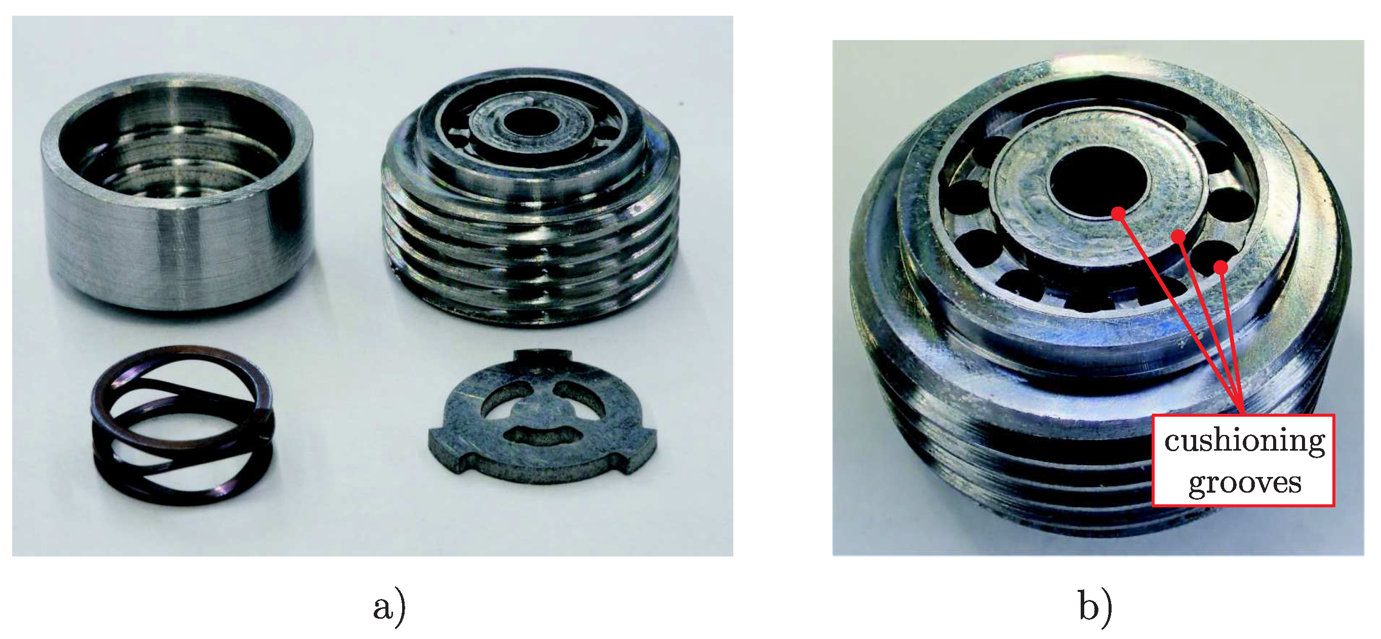
To reduce the landing speed of the plate at the end stops (and further to limit the wear and noise), a novel groove cushioning mechanism is applied. This kind of cushioning groove is a very simple, compact and cheap solution and can be integrated easily. Also well-known oil stiction problems of parallel gaps, as a strong response delay, can be minimized. Details to the concept were published by Scheidl et al. [26].
In Figure 10 the prototype of the DCU G3/8 check valve is depicted. The body and the housing are pressed together with an interference fit.
In the simplest possible case check valves are treated as logic elements. The valve opens and the flow can pass if the pressure difference is positive. In the opposite case, the flow is prohibited and the valve closes immediately when is negative.
If the valve response has influence on the overall system behaviour a more elaborate model is necessary. Although the mechanical design of check valves is simple, the detailed physical descriptions of the dynamics and the flow processes are rather complex. With a generic model the influence of various effects and the related design parameters can be studied easily with one simulation model. The structure of the developed check valve model in Simulink, which was used for the simulations, is depicted in Figure 11.
The flow rate can be calculated with CFD simulations or with an analytical model. In both cases the flow rate due to the fluid displacement effect of the moving valve plate can be included. The pressure force can be determined from the CFD simulation results or with an analytical model by specifying the active area on which the pressure acts and a flow force coefficient. The plate dynamics are modelled with the momentum equation of the valve plate.
The squeeze and stiction force model is also part of the generic simulation model. More details about the squeeze and stiction force model as well as the other modelled effects were published by Leati et al. [27].
Calculations based on analytical models only provide an initial approximation of the characteristic of the valve. With the power of CFD tools, advanced numerical analysis can be done to identify the flow and force characteristics of valves. The developed check valve was extensively analysed by means of the open source CFD software OpenFoam.
The geometry of the check valve is assumed to be axisymmetric. Due to the design of the valve the spring is not considered. The wedge shaped computational domain has been discretised by hexahedral cells. The grid resolution in the gap between plate and housing is 190 points in radial and 18 points in axial direction and corresponds to an average cells size of ≈. Figure 12 shows the computational domain and the corresponding mesh (for visibility each second point is shown only).
The 3d mesh with a resolution of 200 points around the circumference was generated by rotating the 2d mesh around the central axis. The generated mesh has one million hexahedral cells.
A mesh convergence study was carried out for the 3d and 2d meshes by computations with coarser and finer resolutions. For the 2d simulations (laminar and SST turbulence model) the mesh with 25,000 cells is sufficiently fine to predict the flow behaviour of the check valve. The mesh resolution of one million cells in 3d delivers quite good results for laminar and LES simulations. For a Direct Numerical Simulation (DNS) a finer resolution in several areas is necessary to resolve the smallest eddies. The final mesh for the DNS has two million cells and meets the requirements of the Kolmogorov microscale for small difference pressures. The Kolmogorov microscale is the smallest scale in turbulent flow, in which viscosity dominates and the turbulent kinetic energy is dissipated into heat as described by Hoffmann et al. [28].
On both ports of the valve an uniform pressure boundary condition was applied. The surfaces of the housing and the plate are considered as walls.
A proper estimation of the turbulent phenomena is important to determine the check valve flow characteristics. One of the most suitable turbulence models for this kind of flow is the SST. Default values for the model constants were used. A no-slip boundary condition was imposed on the walls (housing and plate) of the valve. No wall function was used because of the small values near the wall. Also the boundary conditions at the inlet and outlet have to be specified for the turbulent quantities, which were done by specifying the turbulence intensity with 5% and the turbulence length scale (hydraulic diameter of the inlet and outlet). The LES simulations were performed with an one equation eddy viscosity turbulence model with the default values of the model constants.
For the simulations the pimpleFoam solver with linear interpolation schemes was used and convergence of each simulation was checked by means of relative and absolute residuals.
OpenFoam’s dynamic mesh capability is used to simulate problems where the mesh is distorted due to the motion on the boundaries. Also the plate type check valve’s plate motion is fully considered in the remeshing procedures. Therefore the equation of motion of the plate has to be solved at each time step.
There are different dynamic mesh schemes predefined in OpenFoam, namely, smoothing, layering and re-meshing. Also a combination of these three schemes can be used in one case and so the most challenging dynamic mesh problems can be solved. However, the plate motion of the check valve is only a linear boundary motion.
For example the flow characteristics were studied and the transition between the laminar and turbulent flow regime by means of DNS. In Figure 13 the flow through the check valve for two different pressures are shown. For example, the simulation needed a computation time of 48 h on 12 cores of an Intel Xeon E5-2680 v3 CPU with 2.5 GHz. The vortices are illustrated by isosurfaces. The -criterion is based on the velocity gradient tensor and proposes that the second largest eigenvalue of the symmetric tensor at each point is negative inside the vortex core (Jeong and Hussain [29]). The gradient velocity tensor can be decomposed in the symmetric components and antisymmetric components . Also the velocity streamlines show the vortices in the flow regime. For the isosurface is symmetric and the streamlines indicate a laminar flow through the valve. The streamlines which have the source on the depicted plane stay on this plane. For a turbulent flow regime the streamlines do not stay in the same plane due to the stochastic behaviour of the flow. For the turbulent streamlines can be seen clearly. The isosurface shows the stochastic structure of the vortices.
In dynamic simulations the mesh changes over time due to the motion of the plate. The layering method is used as depicted in Figure 12. A new dynamic mesh class based on the movingConeTopoFvMesh class was developed. The sixDoFRigidBodyMotion class was included to treat the motion of the plate.
The valve plate has only one translational degree of freedom and a tilting of the plate is not taken into account. A quite fine mesh was used in the area of the closing gap to resolve the flow inside the gap domain.
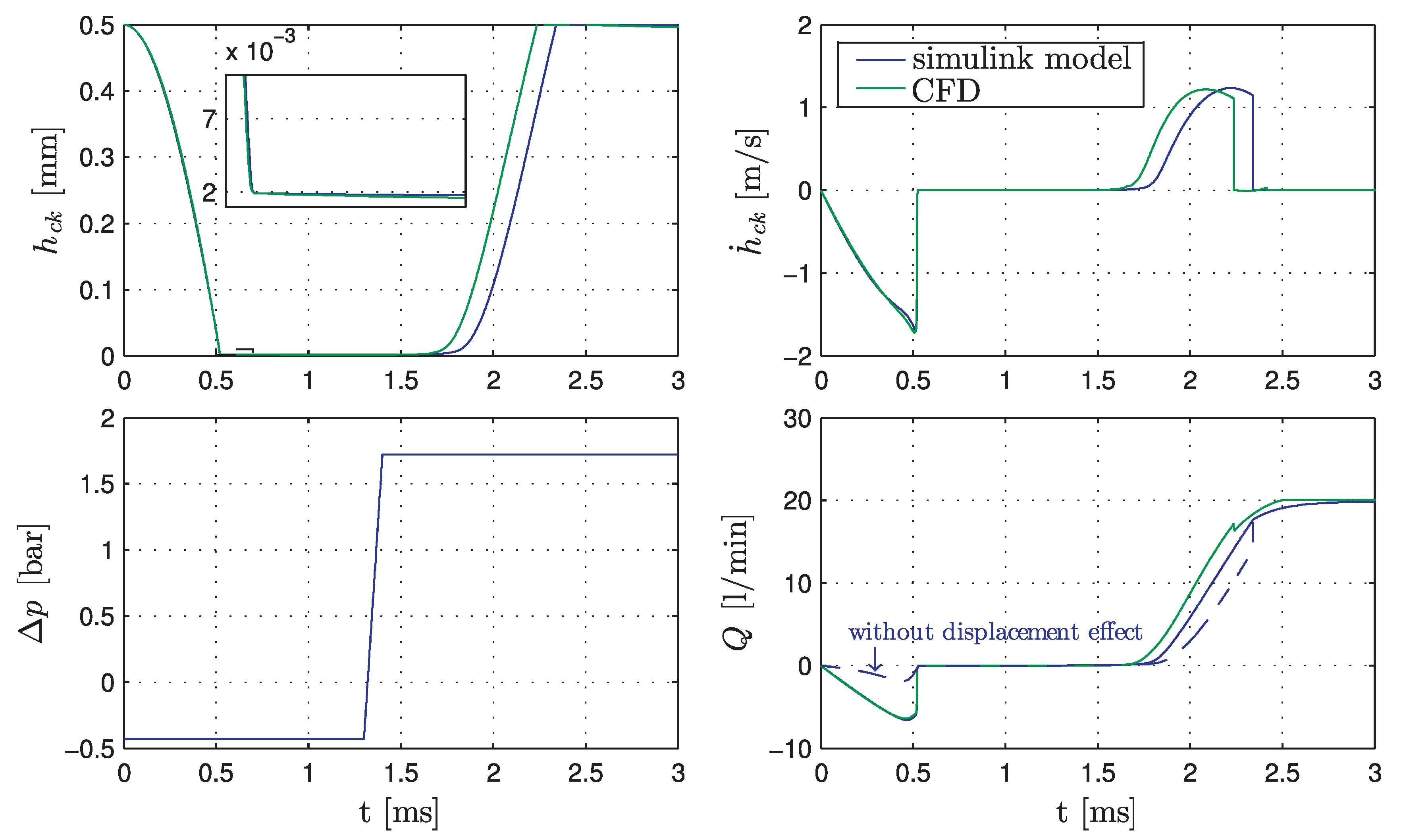
Figure 14 compares the results of the numerical CFD simulation performed by the pimpleDyMFoam solver with the developed simulation model (see Figure 11) for a given difference pressure profile . At the beginning of the simulation the check valve is in the fully opened position and the difference pressure is zero. At the difference pressure is quickly decreased from to . Due to the decreasing pressure and the spring force the plate begins to move and to close the check valve. The oil squeeze force limits the fast closing the check valve. The minimum gap height between valve plate and housing for the closed check valve is below for the given geometry and pressure profile. The minimum gap height influences the magnitude of the stiction force which causes a response delay in valve opening.
At the difference pressure is increased to . The stiction forces cause a substantial response delay in valve opening of approximately . The CFD model response due to the pressure increase is faster than the developed Simulink model. This difference can have various reasons, such as the inductance effects of the inlet and outlet areas or the highly distorted mesh (high aspect ratio) in the fluid gap between housing and plate in the closed position of the valve.
Figure 14 shows a good accordance of the CFD simulation and the simulation model in Simulink depicted in Figure 11 and confirms that the complex flow and motion behaviour can be described with a simplified model which could be included in more complex simulation models of hydraulic circuits with other hydraulic components involved. Further, the influence of the fluid displacement effect to the flow rate during the switching can be clearly seen.
3.2. Combined Hydrostatic Hydrodynamic Bearing System
The initial guidance system depicted in Figure 15 consists of two short steel sleeves to guide the piston made of steel. Between both steel sleeves the position sensor is placed. The corresponding sensor installation chamber is connected to the leakage line. The pistons with the additional masses are oscillating with a frequency up to and an amplitude of . The pressures at both ends of the pistons vary from 0–250 according to the operation principle and depending on the actual load of the hydraulic converter.
The resulting gap geometry results in a destabilizing behaviour of the piston and leads to an increased friction force. As consequence, the energy efficiency is drastically reduced as reported in Figure 8. Hence, an improved guidance system based on elastic deformation was developed. A hydrostatic difference pressure or/and a hydrodynamic pressure deforms a PEEK piston such that a conical stabilizing sealing gap is created. The concept and further details can be found in [30].
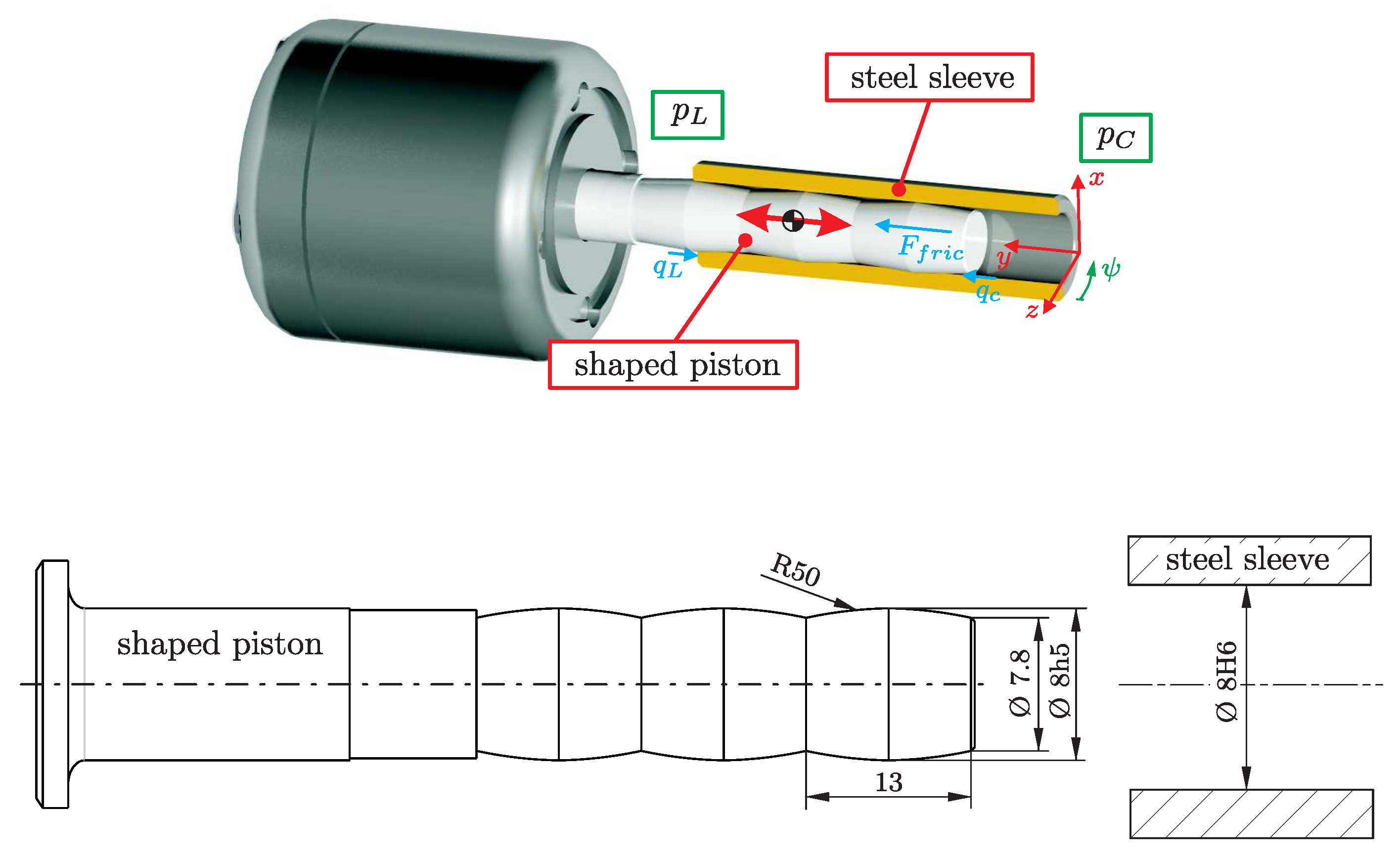
The investigated bearing sleeve cannot be used without small modifications of the HSD. Both steel sleeves and the position sensor are replaced by only one but longer steel sleeve which guides the shaped piston made of PEEK. The chosen concept is depicted in Figure 16.
The diameter of the steel sleeve is specified as . This sleeve can be manufactured by reaming. The maximum diameter of the piston is which is reduced to . The length of one bearing segment is . According to the fitting tolerances the minimum gap height is between 0 and .
To study the characteristics of the bearing system the finite element suite Abaqus was used. A Reynolds User Element was developed and included into Abaqus for the simulation of the fluid structure interaction. The Reynolds equation is discretised by finite elements and solved simultaneously with the mechanical model.
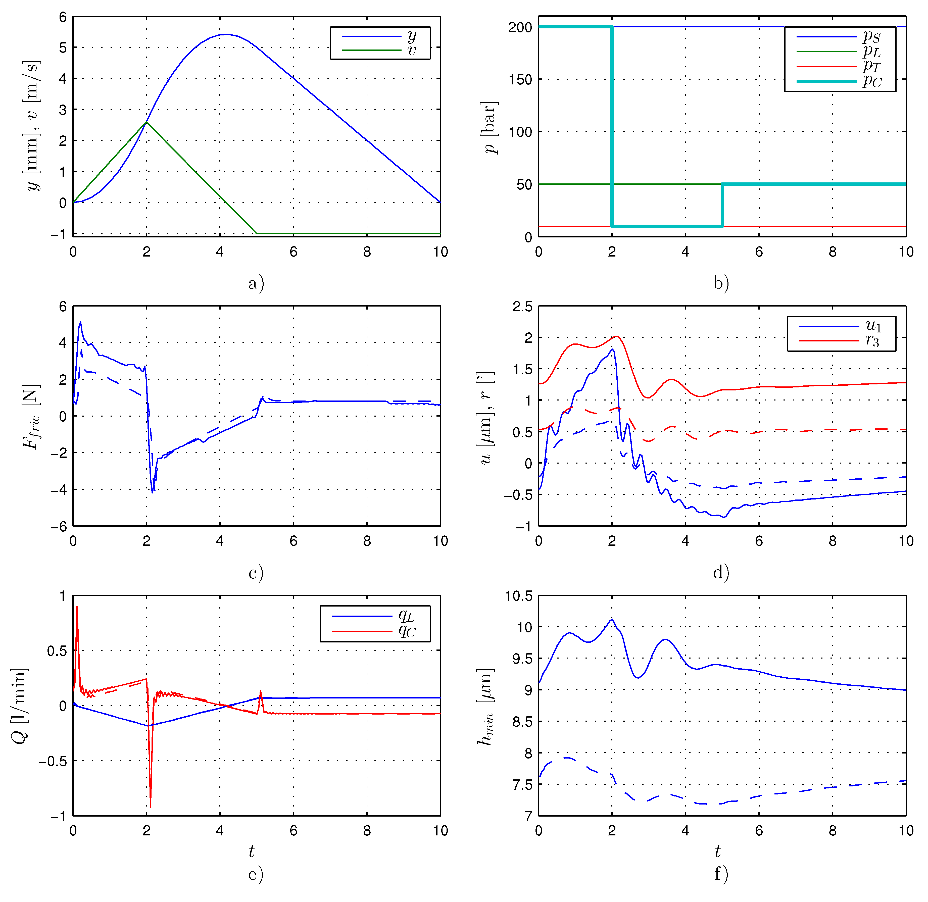
The purpose of the numerical analysis of one operation cycle is to demonstrate the behaviour of the bearing system for variable pressure boundary conditions under normal HSD operation conditions. Simplified position, velocity and boundary pressure profiles as depicted in Figure 17a,b were used for the following Abaqus simulations. The system pressure , tank pressure and load pressure are set to , and , respectively. The chamber pressure is switched between these values.
In Figure 17c–f the simulation results for two values of the minimal nominal fluid gap (solid lines for and dashed lines for ) can be seen. The friction force has its maximum with ≈ near the point of the maximum velocity of the piston as illustrated in Figure 17c. A smaller nominal gap height leads to a reduction of the friction force. Compared to the estimated friction forces of the previous bearing concept (see Figure 15) this is a significant improvement. It should be mentioned that summarizes the Couette and Poiseuille contributions of the shear forces. The results for the eccentricity and tilt in Figure 17d show that the piston is stabilized in an appropriate manner.
The boundary flows and , depicted in Figure 17e, show the influence of the elastic deformation of the piston. The flow rate peaks are at the pressure build up and pressure reduction phases. For the HSD application the elasticity of the pistons acts as additional dead volume. The mean leakage flows through the bearing are a few millilitres per minute. Friction forces and leakages through the gap between piston and sleeve represent the two main sources of energy dissipation.
The minimum fluid film height is for the whole cycle above for the nominal gap height of and above for a nominal gap height of as shown in Figure 17f.
4. Experiments
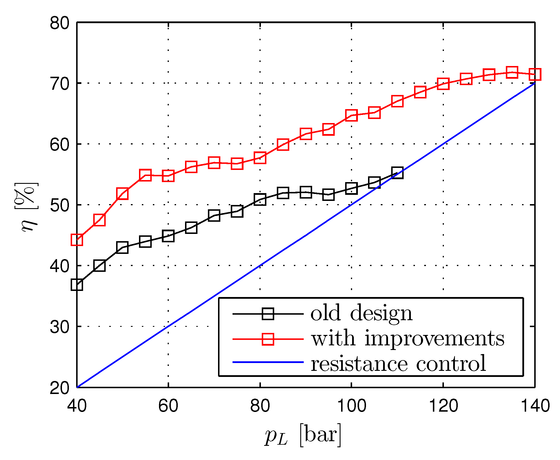
In Figure 18 the energy efficiency and the corresponding flow rates for the first prototype and the prototype with the developed check valve and bearing system are depicted. The flow rate was set to and the chosen frequency was . For the chosen flow rate the maximum hydraulic output power is . The improvement in energy efficiency of up to 15% is largely due to the contribution of the fast check valve.
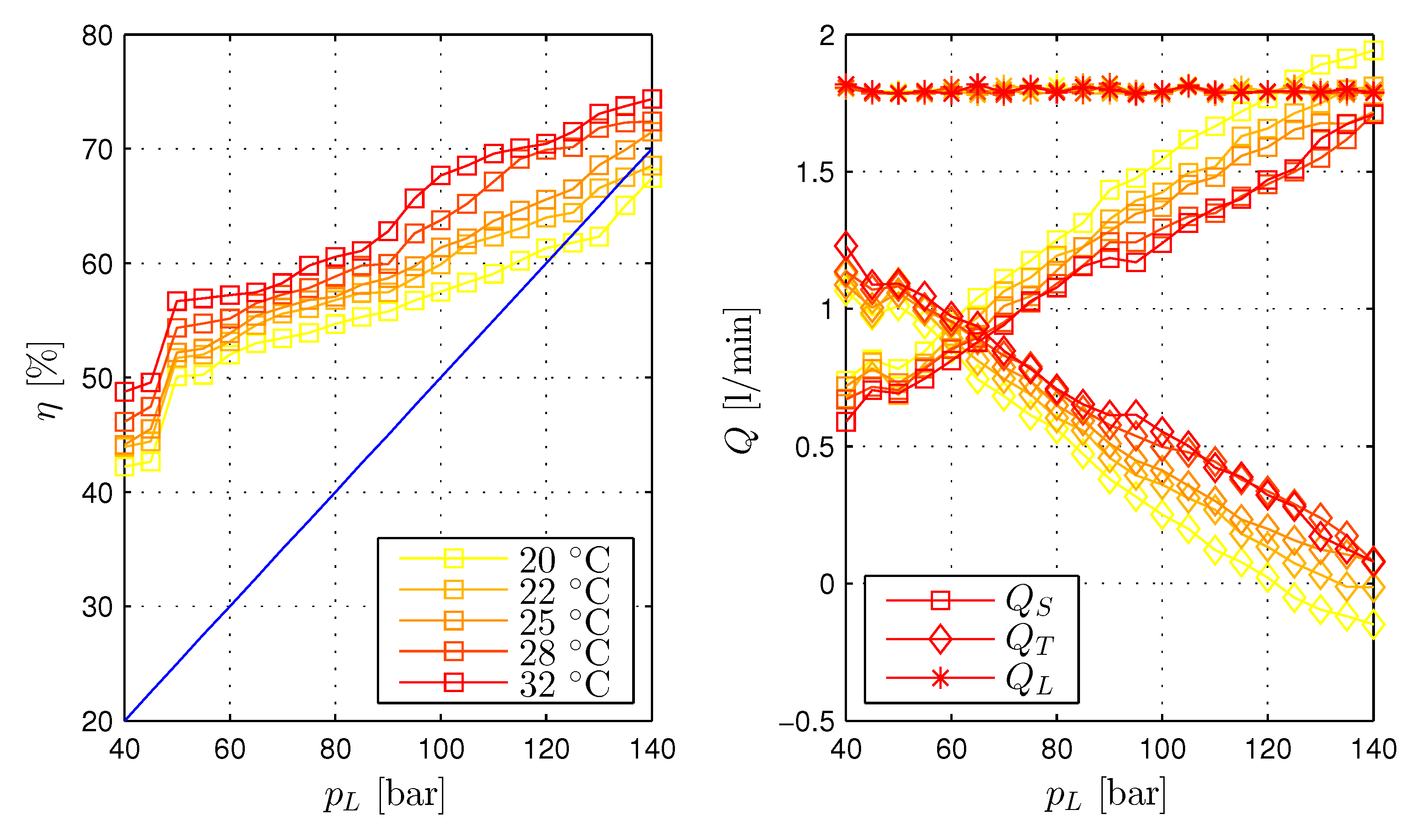
The oil temperature dependence of the energy efficiency is shown in Figure 19. An increase of leads to a ≈5%–10% higher energy efficiency. This higher energy efficiency is caused by a higher tank line flow rate and lower supply line flow rate . For a temperature of and load pressures >150 bar no energy efficiency improvement compared to a resistance control is achievable. For a temperatures of the load pressure with no energy efficiency improvement decreases to .
In Figure 19a substantial efficiency drop for load pressures below can be seen. The pre-charge pressure of the load sided piston accumulator (used to smooth the load pressure due to the flow rate pulses, see Figure 6) was ; it has no influence for load pressures below this value which cause a back pressure in the load line below this pressure. Reducing the pre-charge pressure to , increases the efficiency for a load pressure of from ≈45% to ≈55%. However, the efficiency for higher load pressures decreases slightly.
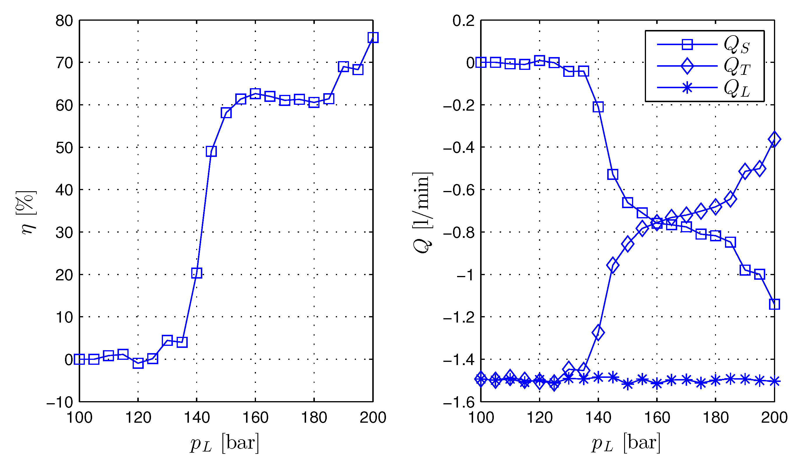
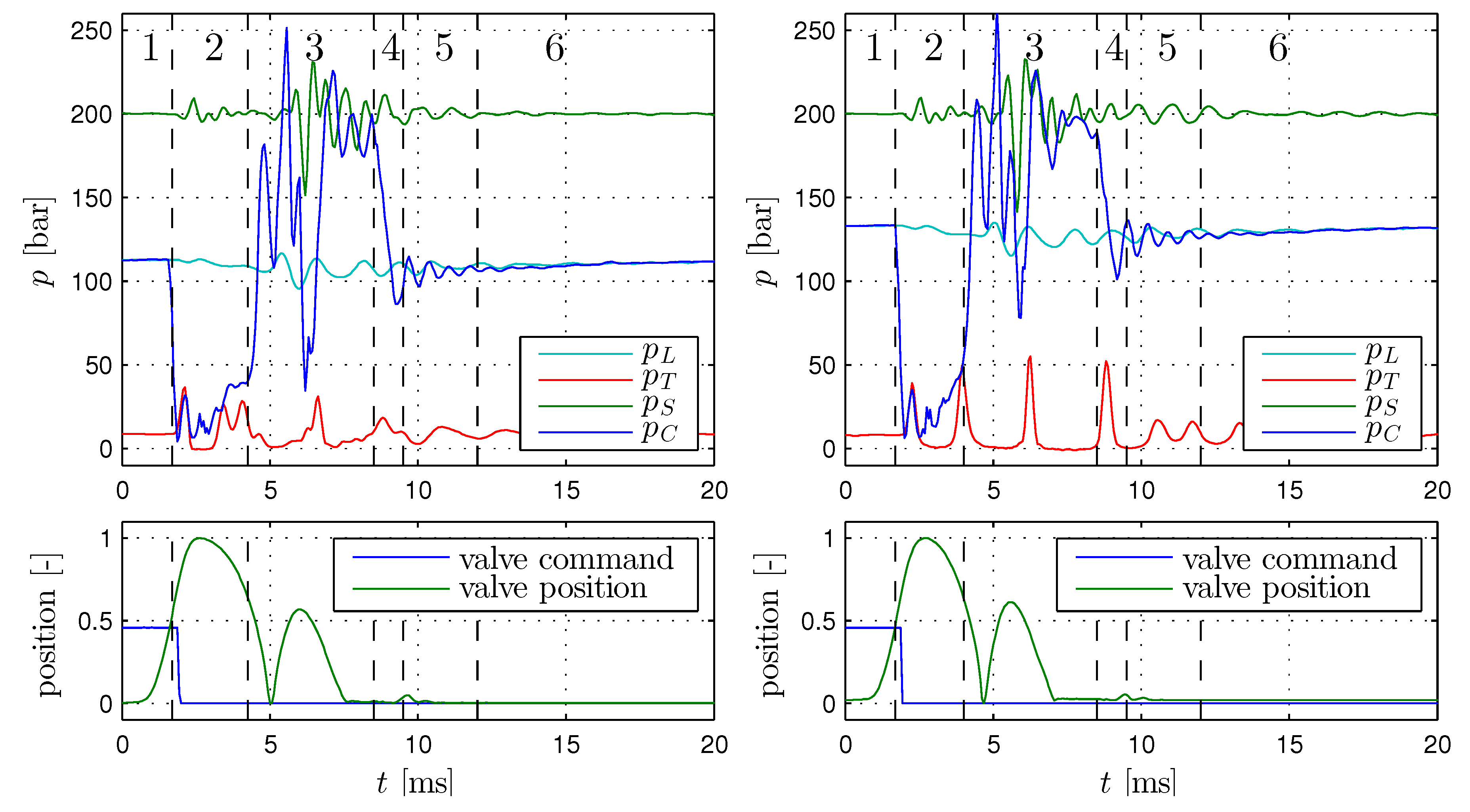
The recuperation energy efficiency is reported in Figure 20. The energy efficiency is for load pressure of above 60%. For smaller load pressures it drops quickly to zero. The fast drop is caused by an re-opening of the switching valve due to pressure pulsations as can be seen in Figure 21. At the valve re-opens the connection to the tank line and the chamber pressure decreases. This interrupts the energy recovery and a relatively huge amount of energy is dissipated in the switching valve. After the valve is closed again, the chamber pressure rises and a small amount of energy is recovered.
The described problem can only be solved by another valve and requires a redesign of the converter block. Further, a slow check valve can cause a back flow from the system pressure line in phases where the chamber pressure falls below the system pressure.
5. Summary and Outlook
A hydraulic stepper converter for an energy efficient control and energy recuperation was developed. A prototype with a hydraulic output power of ≈600 W was manufactured and investigated. With this converter an energy efficiency increase compared to a resistance control up to was measured. The maximum recuperation energy efficiency is over .
The major weakness of the first converter prototype was the piston sealing and guidance system as well as a slow response of the used commercial check valves. Hence, in a second project stage a fast check valve and a combined hydrostatic hydrodynamic bearing system based on the elastic deformation of plastics were developed. The check valve characteristics were extensively studied by means of CFD calculations. The concept of the hydrostatic hydrodynamic bearing system based on elastic deformations was verified by finite element simulations and experiments. Finally, both innovations were incorporated in the converter prototype and led to an improvement of the total energy efficiency of ≈15%.
Future work will be the further improvement of the energy efficiency of the converter and a more compact design.
Acknowledgments
This work has been carried out at LCM GmbH as part of a K2 project. K2 projects are financed using funding from the Austrian COMET-K2 programme. The COMET K2 projects at LCM are supported by the Austrian federal government, the federal state of Upper Austria, the Johannes Kepler University and all of the scientific partners which form part of the K2-COMET Consortium.
Author Contributions
The author’s contribution to the article are equal.
Conflicts of Interest
The authors declare no conflict of interest.
References
- Krieger, M. Untersuchungen zum Energieverbrauch von Hydraulischen Antriebssystemen Eines Walzwerkes. Master’s Thesis, Johannes Kepler University Linz, Linz, Austria, 2014. [Google Scholar]
- Pfeifer, T.; Schmitt, R. Autonome Produktionszellen: Komplexe Produktionsprozesse Flexibel Automatisieren; Springer: Berlin, Germany, 2006. [Google Scholar]
- Zenny, O. Linear Electrohydraulic Pulse Drive Actuator. U.S. Patent 3,899,956, 19 August 1975. [Google Scholar]
- Actuators, A. Hydraulic Stepping Actuator. 2015. Available online: http://www.advanced-actuators.com/hydraulic-stepping-actuator/ (accessed on 16 August 2016).
- Introl, K.K. Subsea Chokes and Control Valves Subsea Chokes and Control Valves. 2010. Available online: http://www.kentintrol.com (accessed on 9 January 2014).
- Cove, H. Linear Hydraulic Stepping Actuator with Fast Close Capabilities. U.S. Patent 2006/0192160, 31 August 2006. [Google Scholar]
- Minav, T.; Laurila, L.; Pyrhönen, J. Relative position control in an electrohydraulic forklift. Int. Rev. Autom. Control (1974-6059) 2010, 6, 54–61. [Google Scholar]
- Bhangu, B.; Bingham, C. GA-tuning of nonlinear observers for sensorless control of automotive power steering IPMSMs. In Proceedings of the 2005 IEEE Vehicle Power and Propulsion Conference, Chicago, IL, USA, 7–9 September 2005; pp. 772–779. [Google Scholar]
- Gradl, C.; Plöckinger, A.; Scheidl, R. Sensorless position control with a hydraulic stepper drive—Concept, compression modeling and experimental investigation. Mechatronics 2016, 35, 91–101. [Google Scholar] [CrossRef]
- Scheidl, R.; Plöckinger, A.; Gradl, C. Hydraulischer Antrieb und Verfahren zum Diskreten Verändern Dessen Positionsausgangs. WO Patent App. PCT/EP2014/071,479, 16 April 2015. [Google Scholar]
- Scheidl, R.; Riha, G. Energy Efficient Switching Control by a Hydraulic ‘Resonance-Converter’. In Proceedings of the Workshop on Power Transmission and Motion Control (PTMC’99)/Bath, Bath, UK, 8–10 September 2009; pp. 267–273. [Google Scholar]
- Scheidl, R.; Kogler, H.; Winkler, B. Hydraulic Switching Control—Objectives, Concepts, Challenges and Potential Applications. Hidraulica 2013, 1, 7–18. [Google Scholar]
- Gall, H.; Senn, K. Freilaufventile-Ansteuerungskonzept zur Energieeinsparung bei hydraulischen Linearantrieben. Hydraul. Pneum. 1994, 38, 38–44. [Google Scholar]
- Gradl, C.; Kovacic, I.; Scheidl, R. Development of an energy saving hydraulic stepper drive. In Proceedings of the 8th FPNI Ph.D Symposium on Fluid Power (FPNI2014), Lappeenranta, Finland, 11–13 June 2014; pp. FPNI2014–7809. [Google Scholar]
- Gradl, C.; Scheidl, R. Simulation and experimental investigations of a iydraulic stepper drive. In Proceedings of the ASME/BATH 2015 Symposium on Fluid Power & Motion Control (FPMC2015), Chicago, IL, USA, 12–14 October 2015. [Google Scholar]
- Gradl, C. Hydraulic Stepper Drive—Conceptual Study, Design and Experiments. Ph.D. Thesis, Johannes Kepler University Linz, Linz, Austria, 2016. [Google Scholar]
- Pan, M.; Johnston, N.; Plummer, A.; Kudzma, S.; Hillis, A. Theoretical and experimental studies of a switched inertance hydraulic system. Proc. Inst. Mech. Eng. Part I J. Syst. Control Eng. 2014, 228, 12–25. [Google Scholar] [CrossRef]
- Gradl, C.; Scheidl, R. A Basic Study on the Response Dynamics of Pulse-Frequency Controlled Digital Hydraulic Drives. In Proceedings of the Bath/ASME Symposium on Fluid Power & Motion Control (FPMC 2013), Sarasota, FL, USA, 6–9 October 2013. [Google Scholar]
- Haas, R.; Lukachev, E.; Scheidl, R. An RC filter for hydraulic switching control with a transmission line between valves and actuator. Int. J. Fluid Power 2014, 15, 139–151. [Google Scholar]
- Haas, R.; Lukachev, E. Optimal feed-forward control of a digital hydraulic drive. Proc. Inst. Mech. Eng. Part I J. Syst. Control Eng. 2016. [Google Scholar] [CrossRef]
- Kogler, H.; Scheidl, R. The hydraulic buck converter exploiting the load capacitance. In Proceedings of the 8th International Fluid Power Conference (8. IFK), Dresden, Germany, 26–28 March 2012; Volume 2, pp. 297–309. [Google Scholar]
- Ploeckinger, A.; Winkler, B.; Scheidl, R. Development and prototyping of a compact, fast 3/2 way switching valve with integrated onboard electronics. In Proceedings of the 11th Scandinavian International Conference on Fluid Power, Linköping, Sweden, 2–4 June 2009. [Google Scholar]
- Leati, E. Design and Test of an Electromagnetically Actuated High Frequency Oscillation Pump. Ph.D. Thesis, Johannes Kepler University Linz, Linz, Austria, 2016. [Google Scholar]
- Kogler, H. The Hydraulic Buck Converter-Conceptual Study and Experiments. Ph.D. Thesis, Linz Center of Mechatronics GmbH, Linz, Austria, 2012. [Google Scholar]
- Smalley. Metric Series Wave Springs. 2016. Available online: http://www.smalley.com (accessed on 16 August 2016).
- Scheidl, R.; Gradl, C.; Plöckinger, A. The Cushioning Groove for Solenoid Switching Valves—Concept and Theoretical Analysis. JFPS Int. J. Fluid Power Syst. 2014, 8, 76–81. [Google Scholar] [CrossRef]
- Leati, E.; Gradl, C.; Scheidl, R. Modeling of a fast plate type hydraulic check valve. J. Dyn. Syst. Meas. Control 2016, 138, 061002. [Google Scholar] [CrossRef]
- Hoffmann, K.A.; Chiang, S.T. Computational Fluid Dynamics; Engineering Education System: Wichita, KS, USA, 2000. [Google Scholar]
- Jeong, J.; Hussain, F. On the identification of a vortex. J. Fluid Mech. 1995, 285, 69–94. [Google Scholar] [CrossRef]
- Gradl, C. A Combined Hydrostatic Hydrodynamic Bearing Based on Elastic Deformation. In Proceedings of the ASME 2016 9th FPNI Ph.D. Symposium on Fluid Power, Florianópolis, Brazil, 26–28 October 2016. [Google Scholar]
Figure 1.
Hydraulic Stepper Unit test rig.
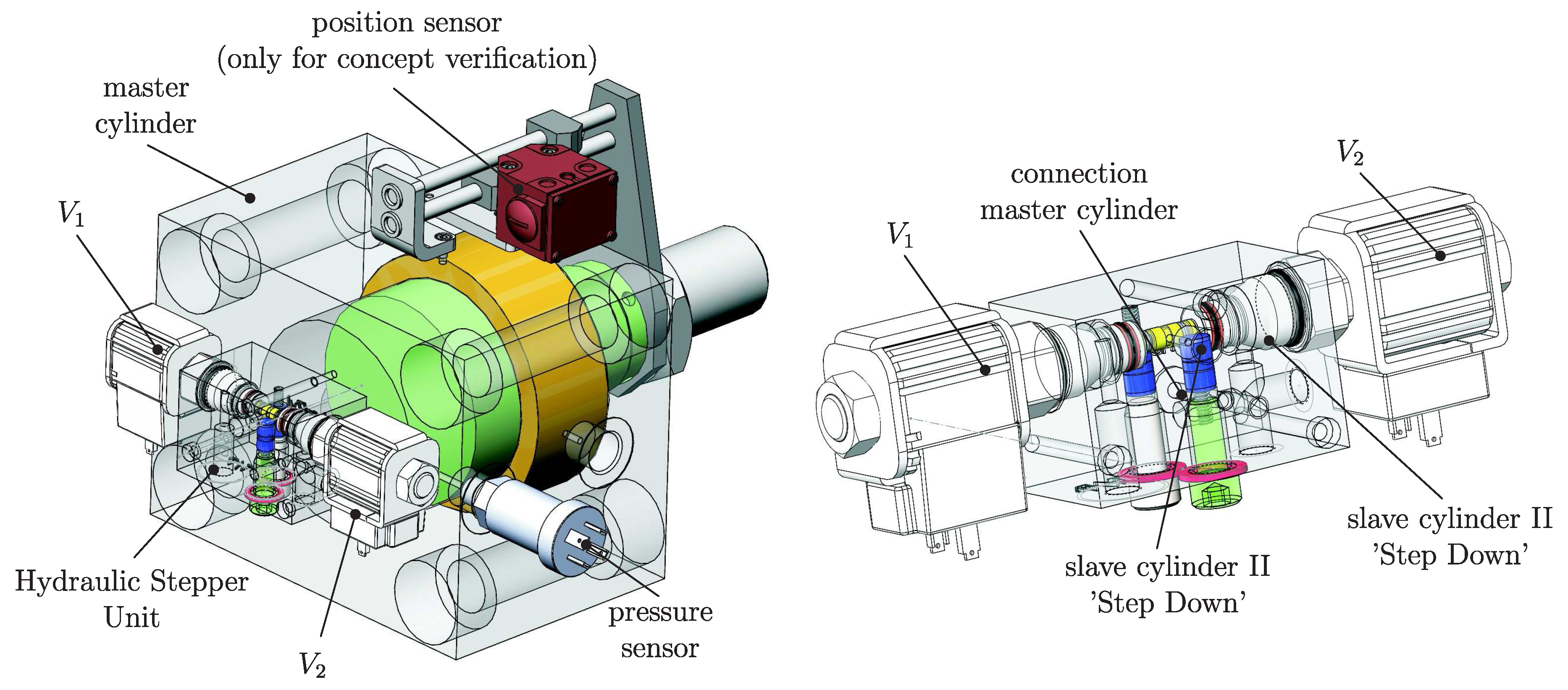
Figure 2.
Schematic of the Hydraulic Stepper Unit and timing diagram.

Figure 3.
Principle of a Hydraulic Stepper Drive (HSD) for the retraction and extension of a hydraulic plunger cylinder (left) and the time diagram of the position and of the corresponding control signals (right).
Figure 3.
Principle of a Hydraulic Stepper Drive (HSD) for the retraction and extension of a hydraulic plunger cylinder (left) and the time diagram of the position and of the corresponding control signals (right).

Figure 4.
Operation cycle (a–e) and the corresponding control signals (f).
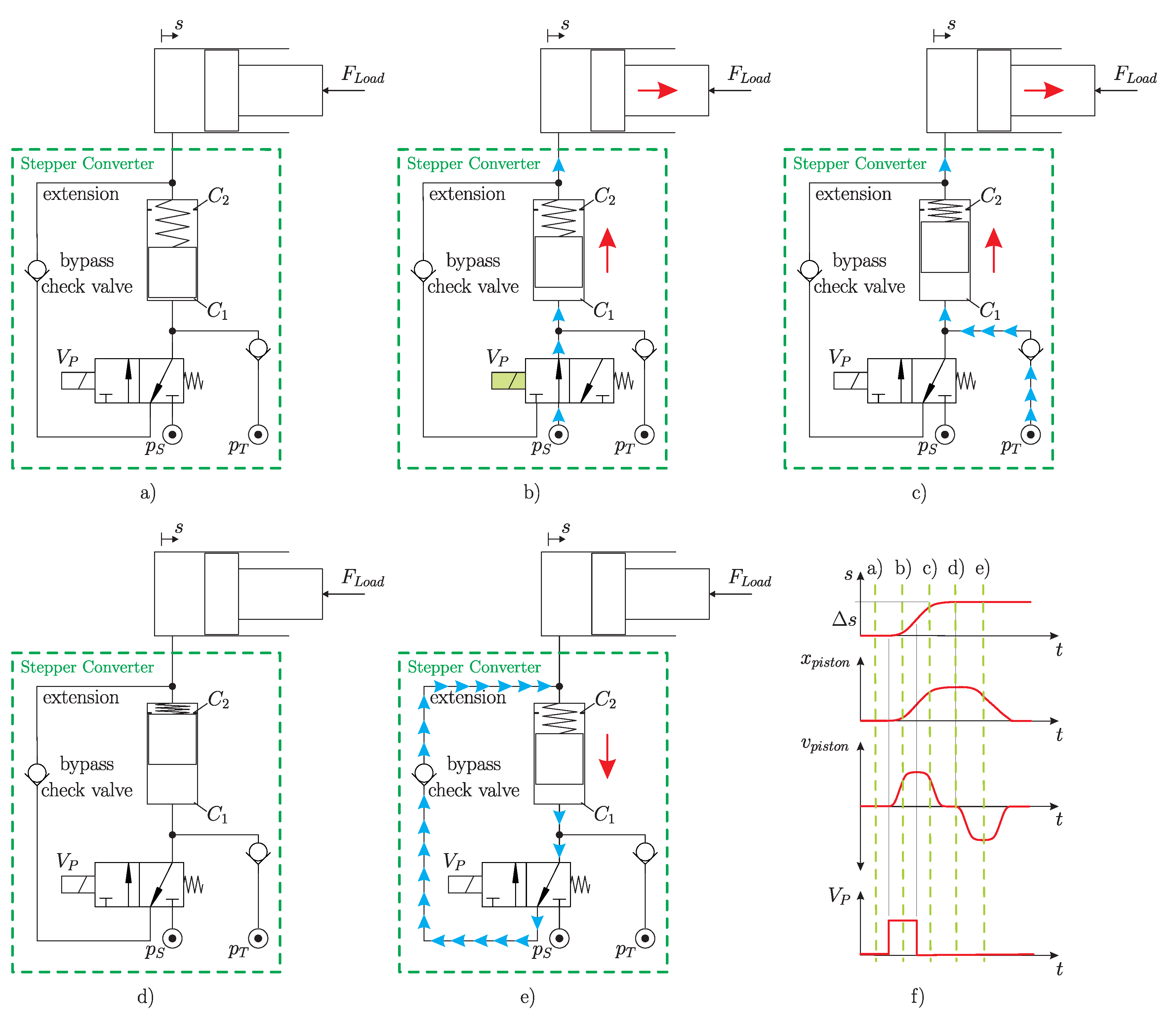
Figure 5.
Energy saving HSD for extension (a) and the retraction (b) of a hydraulic drive with the corresponding control signals.
Figure 5.
Energy saving HSD for extension (a) and the retraction (b) of a hydraulic drive with the corresponding control signals.

Figure 6.
Mechanical design of the HSD with the main components.

Figure 7.
Simulated energy efficiency of the HSD.

Figure 8.
Share of different loss effects of the HSD.
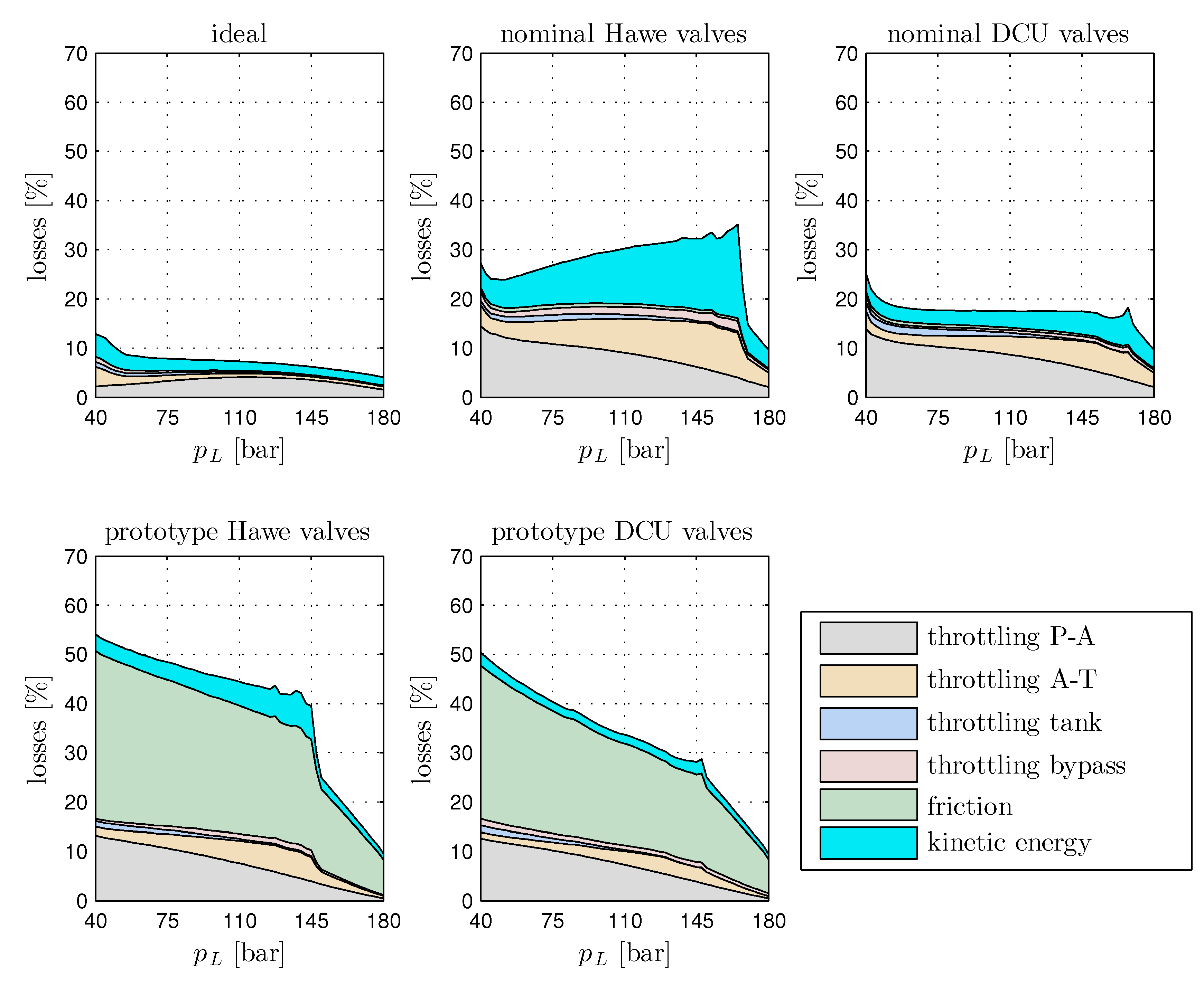
Figure 9.
Mechanical design of the plate type check valve G 3/8″ (1: Body; 2: Plate; 3: Spring; 4: O-Ring; 5: Housing).
Figure 9.
Mechanical design of the plate type check valve G 3/8″ (1: Body; 2: Plate; 3: Spring; 4: O-Ring; 5: Housing).
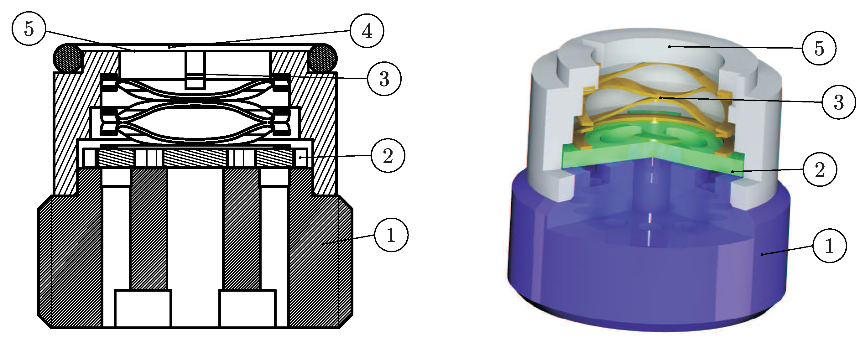
Figure 10.
Design and realization of the plate type check valve G 3/8″ (a) with a cushioning groove (b).
Figure 10.
Design and realization of the plate type check valve G 3/8″ (a) with a cushioning groove (b).

Figure 11.
Developed simulation model of the check valve in Simulink.
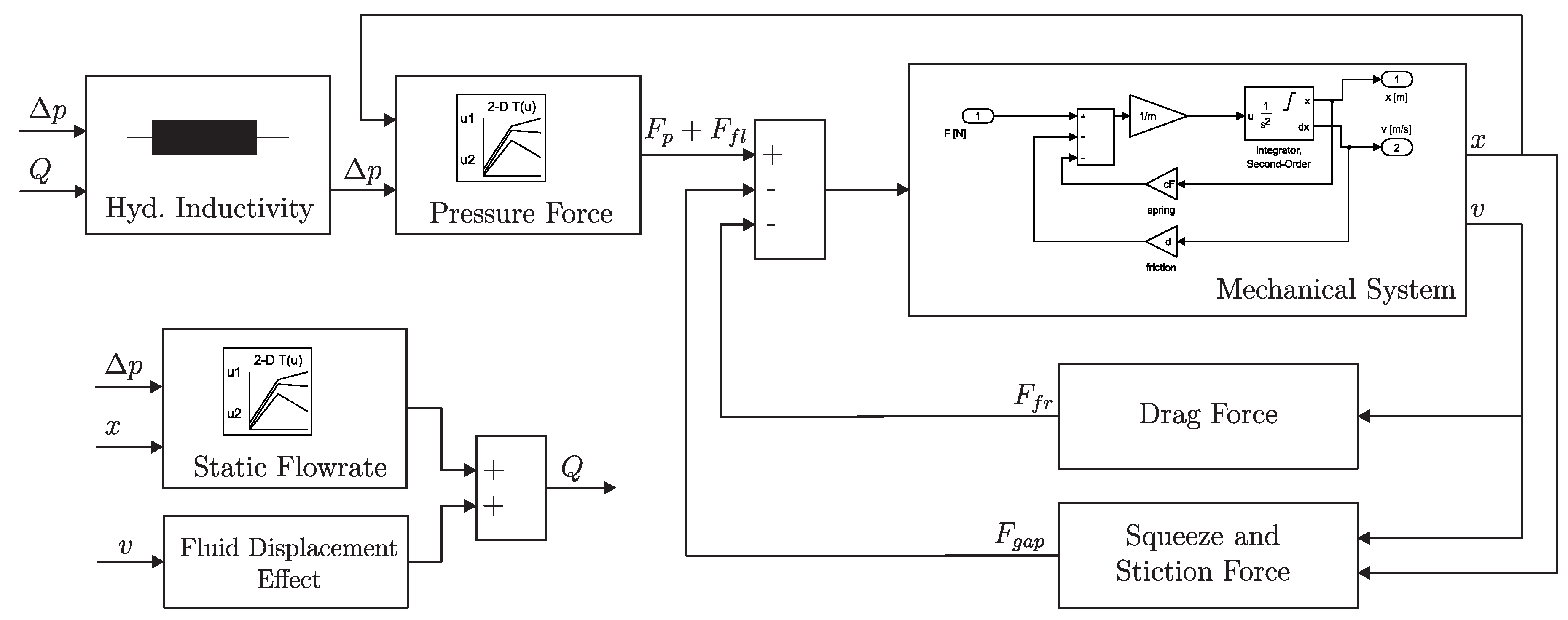
Figure 12.
Axisymmetric CFD model (a) and corresponding mesh (b).
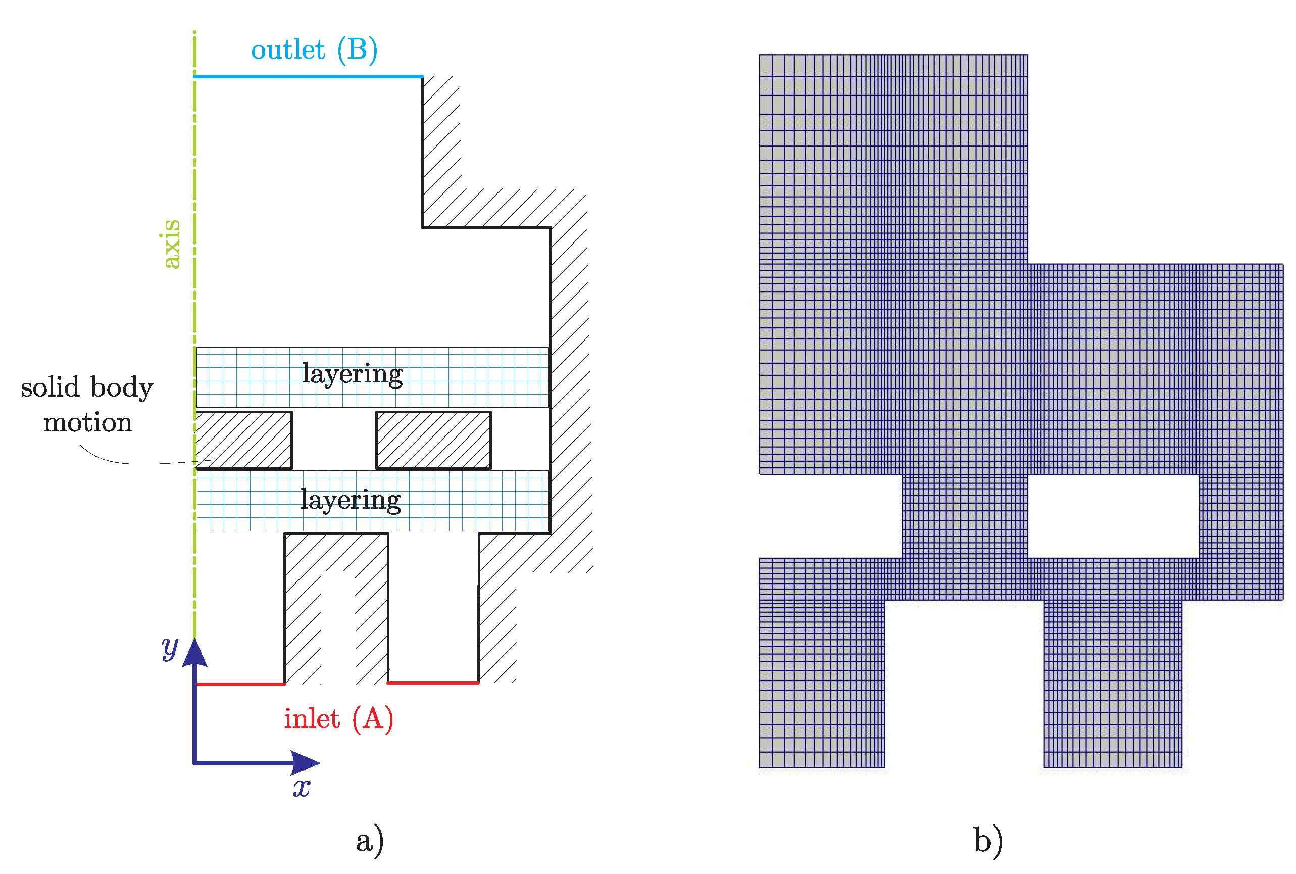
Figure 13.
Flow through the check valve for (isosurfaces of ) (left) and (isosurfaces of ) (right)—isosurfaces coloured according to the pressure and streamlines coloured according to the velocity magnitude.
Figure 13.
Flow through the check valve for (isosurfaces of ) (left) and (isosurfaces of ) (right)—isosurfaces coloured according to the pressure and streamlines coloured according to the velocity magnitude.
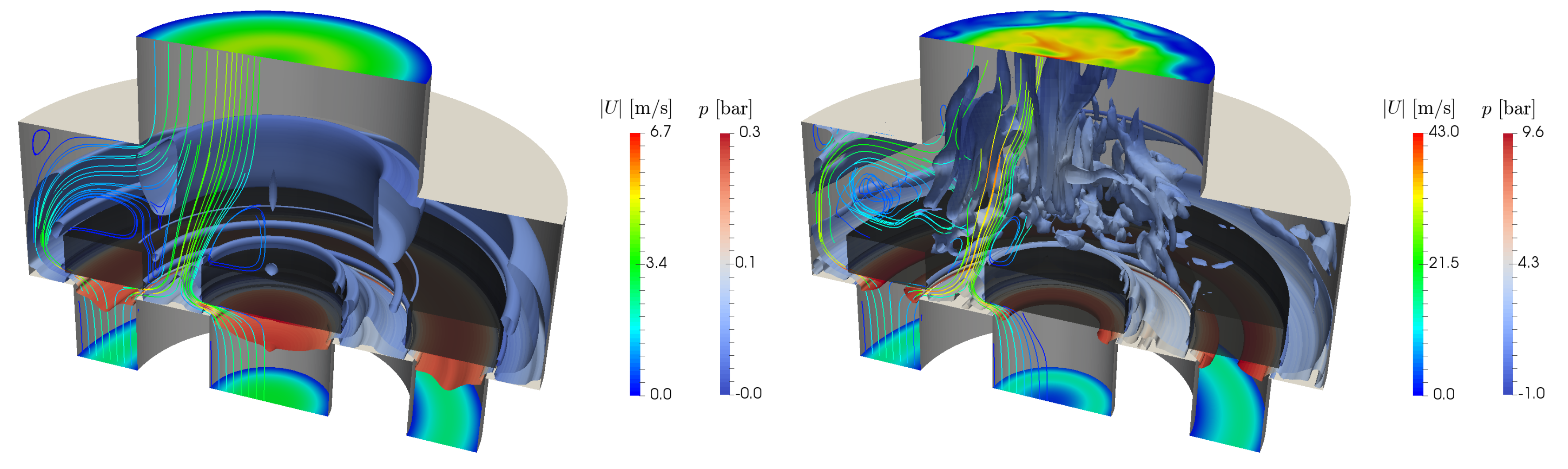
Figure 14.
Comparison of the numerical CFD simulation and the Simulink simulation.

Figure 15.
Sealing and guidance system of the Hydraulic Stepper Drive.
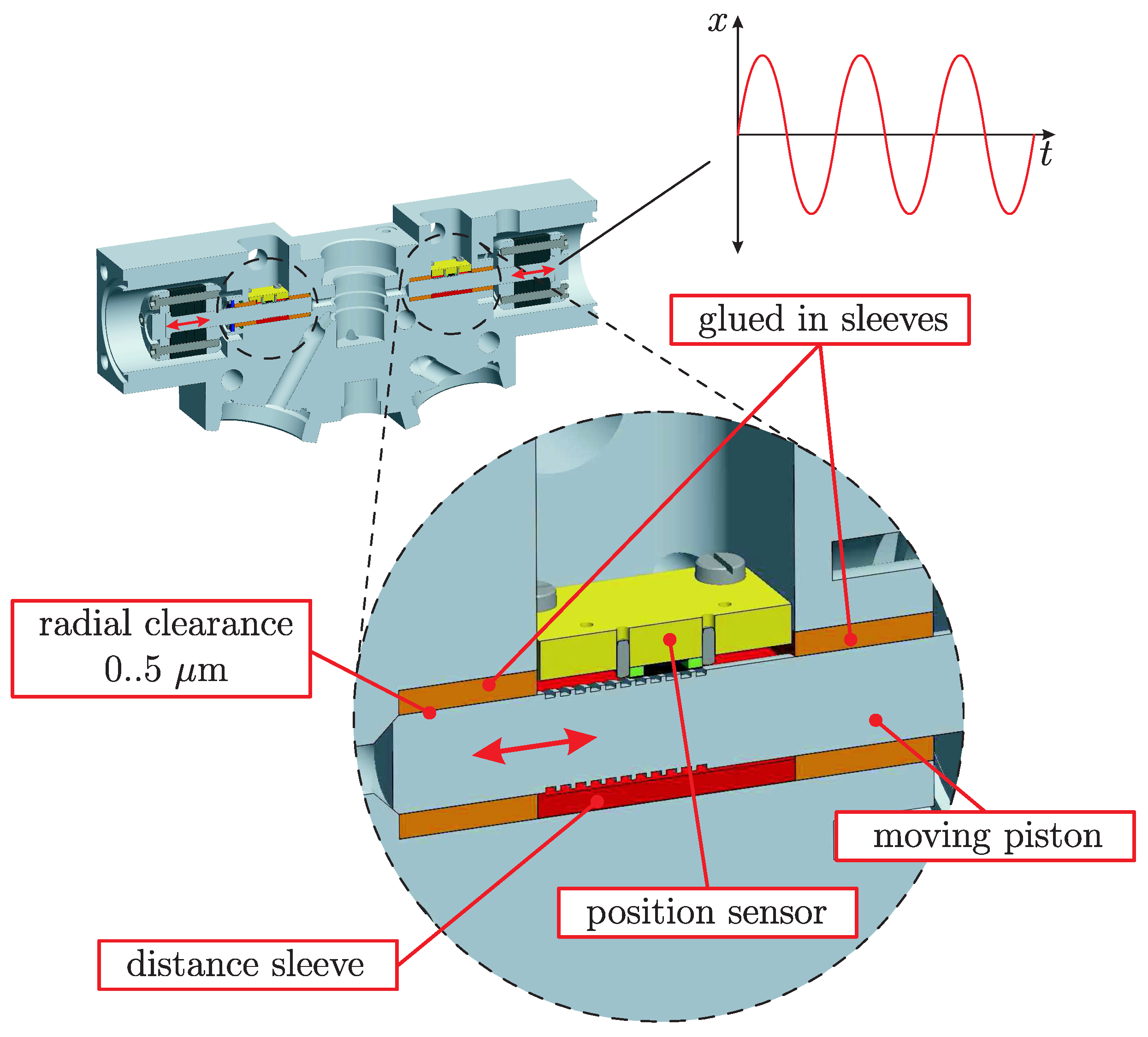
Figure 16.
Bearing design based on a shaped elastic piston for the Hydraulic Stepper Drive.

Figure 17.
Simulation results for one cycle of the converter for a operation frequency of (a,b) and two minimal nominal fluid gap heights (c–f).
Figure 17.
Simulation results for one cycle of the converter for a operation frequency of (a,b) and two minimal nominal fluid gap heights (c–f).

Figure 18.
Energy efficiency comparison , and .

Figure 19.
Energy efficiency (left) and flow rates temperature (right) dependence for and .

Figure 20.
Recuperation energy efficiency (left) and flow rates (right) for , and .

Figure 21.
One recuperation operation cycle for load pressures of (left) and (right).


Table 1.
Nominal mechanical parameters of the plate type check valve G 3/8″ and G1/4″.
| Parameter | DCU G3/8 | DCU G1/4 |
|---|---|---|
| nominal flow rate | ||
| mass of the plate | ||
| spring rate | ||
| spring preload |
© 2017 by the authors. Licensee MDPI, Basel, Switzerland. This article is an open access article distributed under the terms and conditions of the Creative Commons Attribution (CC BY) license (http://creativecommons.org/licenses/by/4.0/).
Share and Cite
MDPI and ACS Style
Gradl, C.; Scheidl, R. Performance of an Energy Efficient Low Power Stepper Converter. Energies 2017, 10, 445. https://doi.org/10.3390/en10040445
AMA Style
Gradl C, Scheidl R. Performance of an Energy Efficient Low Power Stepper Converter. Energies. 2017; 10(4):445. https://doi.org/10.3390/en10040445
Chicago/Turabian StyleGradl, Christoph, and Rudolf Scheidl. 2017. "Performance of an Energy Efficient Low Power Stepper Converter" Energies 10, no. 4: 445. https://doi.org/10.3390/en10040445
Note that from the first issue of 2016, this journal uses article numbers instead of page numbers. See further details here.