Optimal Design of a Novel Hybrid Electric Powertrain for Tracked Vehicles

1
Department of Automobile Engineering, State Key Laboratory of Automotive Safety and Energy, Tsinghua University, Beijing 100084, China
2
Department of Mechanical Engineering, University of Michigan, Ann Arbor, MI 48109, USA
*
Author to whom correspondence should be addressed.
Energies 2017, 10(12), 2141; https://doi.org/10.3390/en10122141
Submission received: 5 December 2017
/
Revised: 9 December 2017
/
Accepted: 9 December 2017
/
Published: 15 December 2017
(This article belongs to the Section F: Electrical Engineering)
Abstract
:Tracked vehicles have been widely used in construction, agriculture, and the military. Major problems facing the industry, however, are high emissions and fuel consumption. Hybrid electric tracked vehicles have thus become increasingly popular because of their improved fuel economy and reduced emissions. While the series hybrid system has drawn the most attention and has been applied in most cases, the low efficiency caused by energy conversion losses and large propulsion motors has limited its development. A novel multi-mode powertrain with two output shafts controlling each side of the track independently is first proposed. The powertrain is a three-planetary-gear power-split system with one engine, three motors, and an ultracapacitor pack. Compared with the existing technologies, the proposed powertrain can realize skid steering without an extra steering mechanism, and significantly improve the overall efficiency. To demonstrate the advantages of the novel powertrain, a topology-control-size integrated optimization problem is solved based on drivability, fuel economy, and cost. Final simulation results show that the optimized design with downsized components can produce about a 30% improvement in drivability and a 15% improvement in fuel economy compared with the commonly used series hybrid benchmark. Moreover, the optimized design is verified to be much more economical taking cumulative cost into account, which is very attractive for potential industrial applications in the future.
1. Introduction
Tracked vehicles have been widely used as construction machinery or military transportation. One type of tracked vehicles is a track-type dozer (TTD), which has been used in high-speed rail construction or building construction. The problem, however, is that the engine exhaust emissions can be twice that of passenger vehicles, which has brought about serious adverse impacts such as air pollution [1]. Many countries have set up emissions requirements for off-road construction machinery [2].
Hybrid electric tracked vehicles for construction have appeared on the market, with Caterpillar producing the first hybrid electric TTD in 2008. The CO and NOx emissions were reduced by 0% compared with conventional models, together with a 25% improvement in fuel economy [3]. The three main types of hybrid electric TTDs are the series hybrid, parallel hybrid, and power-split hybrid. Until now, the series hybrid has been commercialized and researched widely for TTDs. Apart from the D7E, Komatsu, and Kobelco, many other companies also developed series hybrid TTDs [4]. Research has also been done on series hybrid tracked vehicles [5]. Wang proposed a series hybrid TTD and used model predictive control to solve the energy management problem [6,7]. Liu used a reinforcement learning-based adaptive energy management by establishing the control oriented model of the series hybrid vehicles [8]. The series hybrid, however, always suffers from high power conversion losses, which cannot guarantee overall efficiency. Parallel hybrid TTD has rarely been used since the engine is inefficient at low speeds and performance improves little. The power-split hybrid has been widely researched but rarely used. The power-split hybrid can integrate the advantages of the series and parallel hybrid. Nevertheless, for TTD, the power-split hybrid usually requires an extra steering mechanism with an extra steering motor to realize skid steering. Schmidt proposed a dual-mode power-split hybrid powertrain with a specialized steering motor, which can be more fuel efficient [9]. Since the steering mechanism makes the structure more complicated, however, companies are reluctant to produce them.
A crucial design issue for tracked vehicles is the dynamics of skid steering, as tracked vehicles tend to consume more power during skid steering than straight driving [10]. Thus, for series hybrids without an extra steering mechanism, the motor size is usually large, which is another disadvantage. Even series hybrid tracked vehicles sometimes need an extra steering mechanism to satisfy the steering requirements. Han devised an improved series hybrid powertrain with planetary gears collocated between two driving motors on both sides of the tracks, allowing a reduction in the power size of the propulsion motors [11]. The structure, however, became more complex.
What happens if there is no extra steering mechanism in a power-split hybrid TTDs. The structure will be greatly simplified with higher overall efficiency, possibly resulting in new ideas for the tracked vehicle design. This paper proposes a novel multi-mode power-split hybrid powertrain that overcomes the skid steering issue without an extra steering mechanism. The powertrain has two output shafts connected with both sides of the tracks, respectively, and provides torques to each side of the track independently to ensure skid steering.
The novel powertrain for TTD is a three-planetary-gear power-split system. Since Toyota released the Prius as the first generation of power-split hybrid cars, a similar power-split system using planetary gears (PGs) has been widely researched for passenger cars. Two other famous power-split vehicles, the Chevy Volt and the Ford Fusion, were developed as plug-in hybrids. From using one single PG to three PGs, the power-split system has proven to be energy-efficient and promising [12,13,14]. Matthé analyzed the power-split propulsion system of the commercialized Voltec and illustrated the significant fuel-saving performance [13]. Yoshimura from Toyota first used two outputs in PGs to control the front and rear shafts together [15]. Inspired by the above research, the novel powertrain with 3PG to control the left and right tracks is proposed in this paper.
The optimal design problem of a power-split hybrid system using PGs involves topology, control, and size [16]. Millions of power-split candidate topologies are possible using 3PG with one output [14]. Identifying the superior topology for power-split hybrids is challenging. Liu and Zhang have proposed rapid screening for 2PG topology optimization [17,18]. Zhuang tried to optimize 3PG topology using an approximate method because the candidate number expanded enormously [14]. Control is also important for implementation. Many energy management strategies, such as rule-based control and model predictive control (MPC) have been used without ensuring overall optimality [6,19]. The most popular optimal strategy is dynamic programming (DP), but it suffers from a huge computation load [20]. Other near-optimal strategies, such as the equivalent consumption minimization strategy (ECMS) and power-weighted efficiency analysis for rapid sizing method (PEARS+), produce similar results with faster computation speed compared with DP [18,21].
Component sizes are also important for reducing fuel consumption, emissions, and cost. Heuristic algorithms are an emerging field of study for optimization, especially for multi-variable and multi-objective problems. Many heuristic algorithms have been used to reduce computational load, like using genetic algorithm (GA) [22], particle swarm optimization (PSO) [23], differential evolution algorithm [24], artificial bees algorithm [25], and NSGA-II [26]. Among them, PSO requires few parameters to be tuned and less computational efforts for complex optimization [23]. Accelerated PSO (APSO) is proposed in order to accelerate PSO’s convergence property [27]. However, similar to most heuristic algorithms, APSO sometimes falls into local optima, which may make the optimization results inconsistent. Chaotic mapping strategy can enhance the chaos stability of the algorithm by creating occasional ‘accidents’. The stochastically created point can help escape from local optima [28]. In this paper, chaos-enhanced accelerated particle swarm optimization (CAPSO) using logistic strategy [29] is applied to obtain sizing results with high reputation.
All of the aforementioned research, however, solves either the topology optimization or the size optimization separately. Following the proposed novel powertrain using three PGs in this paper, the integrated optimization problem for power-split tracked vehicles will also be solved. The main contributions of this paper are:
- (1)
- A novel hybrid electric powertrain with two outputs using three PGs is proposed for tracked vehicles. The novel powertrain outperforms current powertrains, which can be promising for future industrial application.
- (2)
- A rapid screening method for hybrid power-split topologies using three PGs has been proposed. The method will help engineers identify superior topologies much more quickly among a great number of candidates. An integrated optimization problem has been solved taking into account the topology, size and control. The method is able to identify an economical optimal design with downsized components. The design procedure can be applied to various vehicle powertrain designs.
The paper is organized as follows. In Section 2, the novel multi-mode powertrain design for TTDs, together with the overall optimization problem, is proposed. In Section 3, the topology optimization of a power-split system using three PGs is discussed, which includes modeling and rapid screening. Section 4 describes the control algorithm, enhanced PEARS+ (E-PEARS+), for tracked vehicles. In Section 5, the integrated optimization problem is solved and the right-sized near-optimal design is compared with the series hybrid TTD. Finally, conclusions are presented in Section 6.
2. The Novel Multi-Mode Hybrid Electric Powertrain
This section provides a concise and precise description of the experimental results, their interpretation, and the experimental conclusions that can be drawn.
Currently, series hybrid is the most popular hybrid type for industrial application. Thus, this paper selects an existing series hybrid TTD, SD-24 TTD from Shantui Construction Machinery Co., Ltd. (Jining, Shangdong, China), as the research benchmark [6]. This series hybrid TTD has one engine, one generator, and two motors. An ultracapacitor pack is used for energy storage since TTDs require many charge/discharge cycles. An ultracapacitor can also satisfy the high instantaneous power demand. The main parameters of this series hybrid TTD are shown in Table 1.
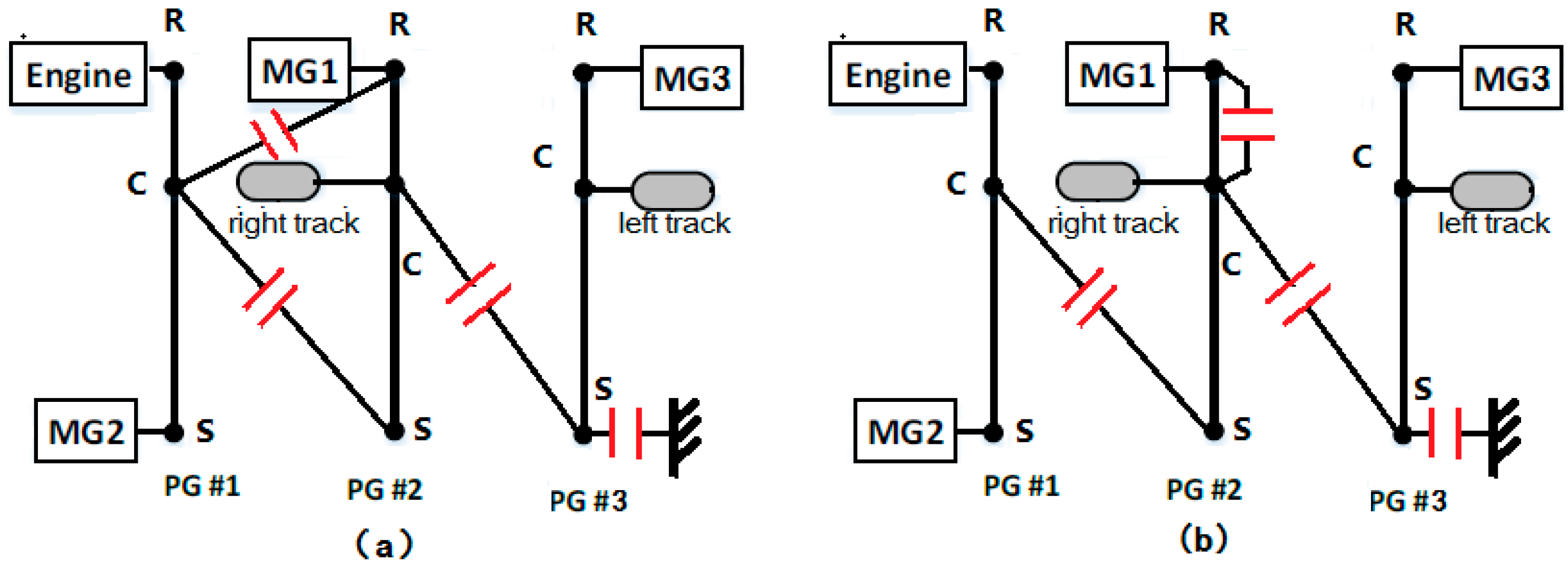
The proposed novel multi-mode powertrain has one engine and two output shafts connected to a 3PG set. To ensure that the two outputs can be controlled independently and that the engine can always operate in the high efficiency area necessitates three motors [30]. The system must have at least two degree of freedom (DOF) to control the two outputs independently; three DOF is needed to ensure high efficiency engine operations. Multi-mode is realized by adding clutches and brakes to nodes in the 3PG set. The schematic diagram of the powertrain appears in Figure 1. To show the advantages of the proposed powertrain, the paper aims to identify better multi-mode hybrid designs than the existing series hybrid TTD. The initial parameters of our powertrain are primarily the same as the series benchmark, the only difference being that the three motors all have the same size as the two driving motors in the series hybrid TTD.
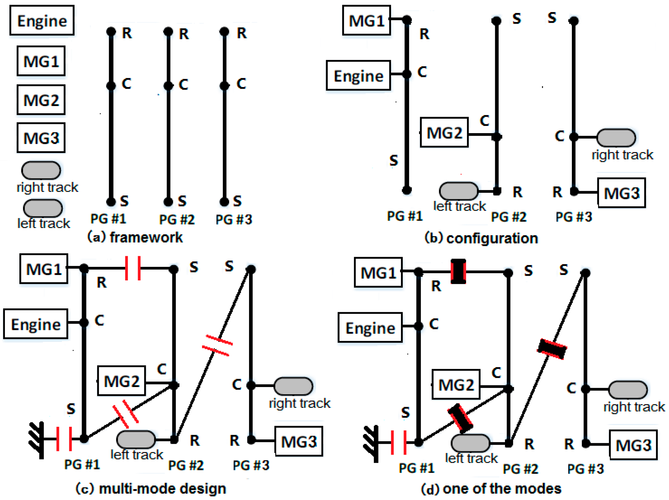
Since there can be a tremendous number of possible connections among PG nodes, components, and clutches, a suitable design generation method is needed. The generation sequence is given in Figure 2 by using a lever diagram, with motor/generator (MG) representing the motor. R, C and S are the ring, carrier and sun gears of the PG. The framework includes 3PG and six components. When six components are connected with nine nodes in 3PG, configuration is generated; when the clutch and brake connections are determined, a design is generated; to achieve two or three DOF, clutches will be either engaged or disengaged, which forms the mode. In Figure 2c, the design has four clutches. When three of the clutches are engaged, a 3-DOF mode is formed, as in Figure 2d.
In this paper, a maximum number of four clutches can be added to one configuration to form a design. Each clutch engaged will add a constraint to the design. The system DOF equals:
where n is the number of PG and c is the constraint number. Thus, the design with four clutches has three 3-DOF modes and one 2-DOF mode.
Based on the generation rules above, all design candidates that satisfy our novel powertrain requirements can be calculated. Six components need to be assigned to nine nodes in 3PG, which forms configurations.
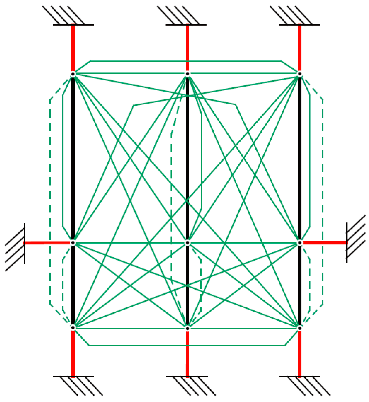
For each configuration, 45 constraint positions are possible for the 3PG set shown in Figure 3, while the six constraints in dashed lines are redundant as connecting any two of the three nodes in one PG results in the same condition. Moreover, the outputs cannot be connected to the brake or to each other, which makes the total feasible constraint number 36. Thus, there are selection ways of four constraints in 3PG. The total number of candidate designs equals . Since analyzing all candidates is impossible, it is essential that the superior designs are identified.
The overall systematic optimization procedure of identifying optimal designs is shown in Figure 4. There are three layers in the process: the design objectives are determined, including basic attributes, performances and cost, which are formulized as the design problem; the second layer will optimize the topologies and screen out the inferior designs by automated modeling and screening, configuration is first generated and screened, design candidates will be analyzed after adding clutches; the third layer will optimize both surviving designs and their sizes in order to obtain the final optimal design. Chaos accelerated particle swarm optimization (CAPSO) together with the novel energy management strategy is used to find the optimal design rapidly. Details will be shown in the following sections.
3. Rapid Modeling and Screening for 3PG Powertrain Design
3.1. Initial Screening of Configurations and Designs
To model and search designs would be time-consuming given the current computing capability. The following process will help reduce the number of all 3PG power-split designs by identifying superior configurations and screening infeasible constraints.
Using a lever diagram, the torque and speed relationship of three nodes in one single PG can be calculated. Note that the inertia of ring, carrier, and sun gears are ignored in this paper for simplification.
Based on Equation (2), we have:
where r and s are the radii of ring and sun gears. and are the speed and torque of nodes. There can be seven different types of configurations with components connected in one single PG, as in Table 2. It should be noted that configurations with two outputs in the same PG are inferior. Moreover, only one component in one PG is unable to be analyzed.
The maximum speed of TTD is approximately 11 km/h, and the maximum towing torque is approximately 60,000 N·m. Thus, according to Table 1, the outputs should satisfy the range in Equation (4), together with the constraints in Equation (5).
subject to:
where is the radius of the driving wheel and is the final drive ratio of the hybrid TTD.
For example, Type No. 1 in Table 2 means that the engine, a motor, and an output are connected with the three nodes in one PG. There can be six different configurations of type No. 1 and the speed relationship can be shown in Figure 5. In these lever diagrams, the black transverse full line represents the speed limit of components; the red line represents the speed changing relationship while the motor and engine is at the maximum or minimum value. It can easily be seen that the first two situations in Figure 5 cannot ensure the speed range of outputs. The last four situations can satisfy the output speed range in Equation (4).
The torque range of the output in Figure 5c–f is further verified. The maximum output torque can be calculated using Equations (2) and (3).
For determined speed of motor and engine, the maximum output torque can be calculated according to the engine and motor map. In this paper, assume that . For each determined motor speed and engine speed combination, search all possible motor and engine toque, and the maximum output torque can be calculated according to Equation (6) and shown in Figure 6.
The maximum output torque of the configuration in Figure 5c can theoretically reach 1400 N·m, which satisfies the maximum torque requirement. However, the maximum output torque of all the other configurations in Figure 5d–f is less than 500 N·m, which cannot satisfy the requirements.
After judging the torque relationship, we can conclude that if the engine, motor, and output are in the three nodes of one PG, the motor should be assigned to ring gear, the output should be assigned to the carrier gear, and the engine should be assigned to the sun gear.
Take Type No. 6 in Table 2 as another example. One motor and one output are connected to two nodes of one PG, while the left node remains unknown. Use subscript 3 to represent this node. The speed cannot be analyzed, while the torque relationship can reveal some rules. There are six situations:
(1) If the output is connected to the ring gear, and the motor is connected to the sun gear in the same PG:
If the maximum output torque is satisfied, the maximum torque of the third node should be at least 1100 N·m, which can hardly be satisfied.
(2) If the output is connected to the ring gear, and the motor is connected to the carrier gear in the same PG:
The maximum output torque can reach 700 N·m while the motor is at maximum torque, and only needs to be 200 N·m. This situation can be implemented.
(3) If the output is connected to the carrier gear, and the motor is connected to the ring gear in the same PG:
The maximum output torque can reach 1000 N·m while the motor is at maximum torque, and only needs to be 400 N·m. This situation can also be implemented.
(4) If the output is connected to the carrier gear, and the motor is connected to the sun gear in the same PG:
While ensuring the output torque range, the motor torque only changes from 0 to 250 N·m, which limits the motor use.
(5) If the output is connected to the sun gear, and the motor is connected to the ring gear in the same PG:
If the maximum output torque is satisfied, the torque of the third node should be at least 2100 N·m, which can hardly be achieved.
(6) If the output is connected to the sun gear, and the motor is connected to the carrier gear in the same PG:
If the maximum output torque is satisfied, the torque of the third node should be at least 1500 N·m, which can hardly be achieved.
Based on the analysis of all six assignment conditions, when one output and one motor are connected with two nodes in one PG, the output and motor should be connected to either the ring gear or the carrier gear.
Using the same method, the connection rules for a configuration can be determined by speed and torque calculation: when engine, output, and motor are in one PG, the motor should be at ring gear, the output at carrier gear, and the engine at sun gear; when two motors and one output are in one PG, the output should be at carrier gear, two motors at ring and sun gears; when two motors and engine are in one PG, the engine should be at carrier gear, two motors at ring and sun gears; when one output and one motor are in one PG, if the output is at carrier gear, motor should be at ring or sun gear. If output is at ring gear, motor should be at carrier gear; when engine and one motor are in one PG, if engine is at carrier gear, motor should be at ring gear. If the engine is at ring gear, the motor should be at sun gear; when the engine and one output are in one PG, the output should be at carrier gear and the engine at ring gear; when two motors are in one PG, they should be at ring and sun gears.
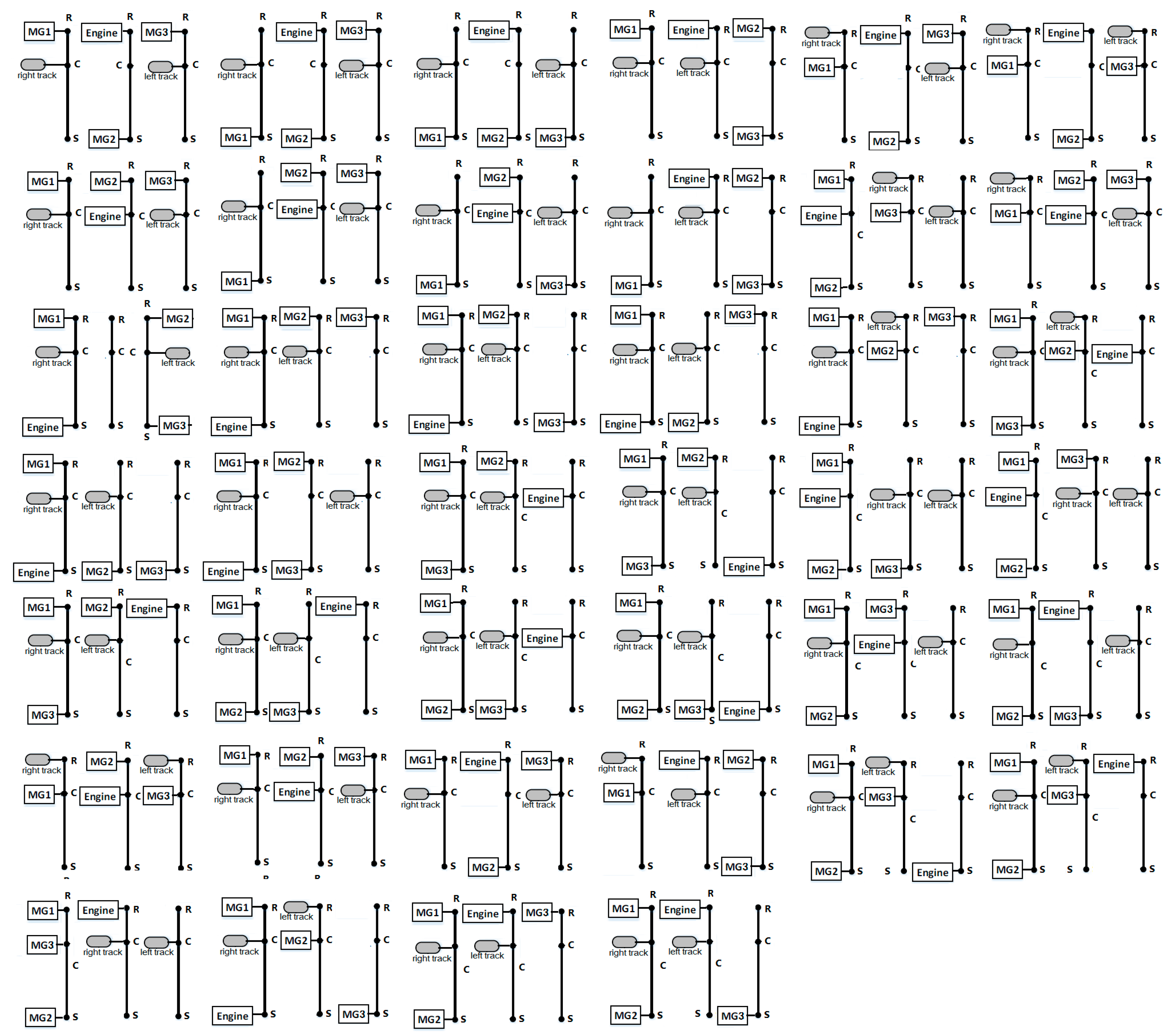
Following these rules, the other feasible connections in Table 2 can be analyzed using the same way and the total configuration number can be reduced from 60,480 to 40. All these 40 superior configurations for our 3PG powertrain are drawn in Figure 7.
Following are the infeasible designs that must be excluded:
- Three connections from one node of a PG to all three nodes of another PG are not allowed.
- Three nodes of a PG are all grounded.
- Two nodes of one PG are connected while the third is grounded.
- Two nodes of a PG are grounded while the left node of this PG is used in another connection.
- Any node of a PG is free without any connection.
Thus, for a single configuration, the feasible design number decreases from to .
Thus, the total candidate design number reduces to , which can be further analyzed.
3.2. Rapid Automated Modeling for Multi-Mode Designs
The details of the speed and torque relationship of all components must be known before analyzing the performance of any design. An automated modeling method is proposed to rapidly analyze the dynamics of each design.
First, the dynamic of the configuration in Figure 2b can be written into a matrix and divided as in Equation (13).
where and are the radii of the ring gear and sun gear of the ith PG set. ,,,, and represent the rotational inertia of the engine, left output, right output and motors. and represent the torque and angular acceleration of the components. , , and represent the internal force of the three PG sets.
Equation (13) is governed by the inertia matrix J, speed, and torque matrices and T, internal force matrix F, and the dynamics matrix D. The modeling method has been proposed in [6].
When adding constraints, the dynamics will change. Define a unit matrix , where n represents the number of planetary gears. Then follow the rules below to manipulate this matrix: if the ath node is connected to the bth node, add the elements of the ath row to the bth row, then remove the ath row; if the ath node is grounded, then remove the ath row. After all constraints are added, the original I matrix is transformed into a new matrix N with a dimension , where c is the number of constraints. Then a new matrix can be generated with the following transformation, and the dynamics of the mode in Figure 2d can be written as follows:
What we care about, however, is the speed and torque relationship between components, which is given in Equation (15):
A* is called the dynamics characteristic matrix, as it reflects all speed and torque relationship corresponding to a determined mode. Matrix A* can be obtained through the derivations that follow.
Assume that:
From Equation (13), it can be seen that .
From Equation (16):
A, B, and C matrices in Equations (18)–(20) are obtained from Equation (17):
The size of A is . However, what we need is A* with the size of , where 6 represents the component number in this design.
Define another Q matrix with the size of in Equation (21):
Then characteristics matrix A* can finally be written as in Equation (22):
Thus, by automatically generating A* matrices, all candidate designs can be easily verified in regard to drivability screening.
3.3. Attribute Screening
Before calculating the detailed performance, several basic attributes must be satisfied for TTDs. The attributes include engine-on driving forwards and backwards, and central steering. These attributes can be directly verified by the elements of the A* matrix shown in Table 3.
Write the second and third row of Equation (15) into Equation (23):
From Equation (23), since the two outputs must be controlled independently, the rows of two outputs must have two DOF, namely, . If the engine can drive the two outputs forward independently, then part of the output driven torque must come from the engine, namely, . Engine-on backwards only needs to switch direction, . Since the output torques of the two tracks have different directions during central steering [10], either the engine or one of the motors must provide the torque differential to achieve skid steering.
For a feasible multi-mode candidate design, these three attributes must be satisfied by any of its modes. After verifying the candidate designs with four clutches, a total number of designs can survive after this step.
3.4. Performance Screening
For TTDs, both straight driving and skid steering are important for operations. To identify designs better than the series hybrid benchmark, straight driving and skid steering features are both verified for each surviving candidate design.
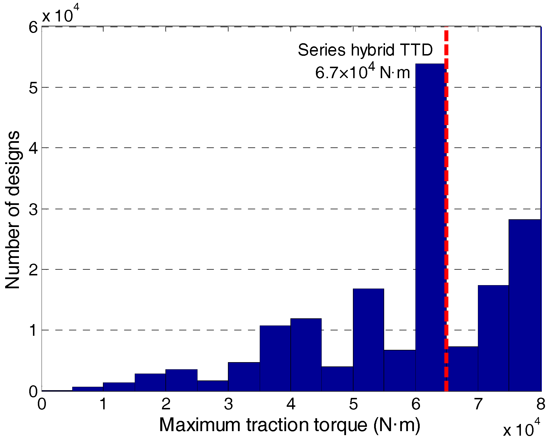
The maximum towing torque, which is the most important feature for TTD due to ISO. 53.100 [10], is first calculated for the series hybrid benchmark and all candidate designs, as shown in Figure 8. A total of designs in designs have a larger maximum torque than the series benchmark.
Among these surviving designs, however, some different designs still share the same dynamic functions. Figure 9 shows an example of two different designs with the same dynamic functions. Since the output cannot be connected with the brake, there are two feasible 3DOF modes for both designs. However, because they share the same dynamics, only one design needs to be retained and the other becomes redundant. Following the verification of each candidate design, 2124 unique designs survive.
The specific performances of the towing and turning capacity at all speeds are calculated in order to prove drivability. In this paper, the average value of all speeds’ maximum traction torques is used to evaluate the straight driving towing capacity, and the average value of all speeds’ minimum turning radius is used to evaluate the turning capacity. In Figure 10, the performance of all designs is compared with the series hybrid benchmark. Sixty-three marked green designs have both better straight driving and turning performances, and are thus selected as the superior designs before integrated optimization.
4. Energy Management Strategy for Rapid Sizing: E-PEARS+
Fuel economy must also be verified for surviving designs. In this paper, the engine and motors (MGs) are both modeled as quasi-static models which are widely used in both industry and academia. The ultracapacitor pack consists of several modules in series or parallel. A simple resistance-capacitance model is used to represent the ultracapacitor pack. The parameters of the pack can be modeled as in Equation (24):
where C is the equivalent capacitance, is the theoretical maximum voltage of the ultracapacitor, is the capacitance voltage, and is the current of the loop. SOC is the state of charge to represent the energy state.
For TTDs, straight driving and turning are both considered. Two typical cycles are selected here, representing straight driving and turning, respectively, in Figure 11a. The straight driving cycle is a typical bulldozing process for TTDs [6]. The blue line represents speed; the green line is the total demand torque on two sides of the tracks. The cycle has five stages: 1∼4 s traveling; 4∼16 s soil-cutting; 16∼31 s soil-transportation; 31∼33 s unloading; and 33∼50 s no-load traveling. The turning cycle, including both left and right turning at different radii, is shown in Figure 11b. The solid line represents the speed and torque of the right track, while the dashed line represents that of the left track. At 1~5 s, the TTD accelerates. At 5~15 s, the TTD turns left with a decreasing turning radius. At 15~17 s, the TTD decelerates and then turns right between 17~22 s. At 24~35 s, the TTD turns right again with a decreasing radius. Then it turns left again from 35 s to 45 s before stopping at 48 s.
Despite the fact that using DP can obtain optimal results for each design, the computation speed is too slow for a large number of candidate designs. PEARS+ was proposed for rapid sizing by analyzing power efficiency, as it had been proven to be able to obtain near-optimal control results in a very short time compared with DP [21].
Instead of using traditional DP to solve the whole problem with a number of states and controls, PEARs+ only use a low-dimensional DP to determine the mode shift, the other controls are determined by maximize the normalized efficiency. PEARS+ can be around 10,000 times faster than traditional DP. This near optimal control strategy, however, cannot be applied to systems with two outputs and cannot be applied to TTDs since the power flow is more complicated. Thus, in this paper, Enhanced PEARS+ (E-PEARS+) is proposed to solve the control problem of powertrains with two outputs.
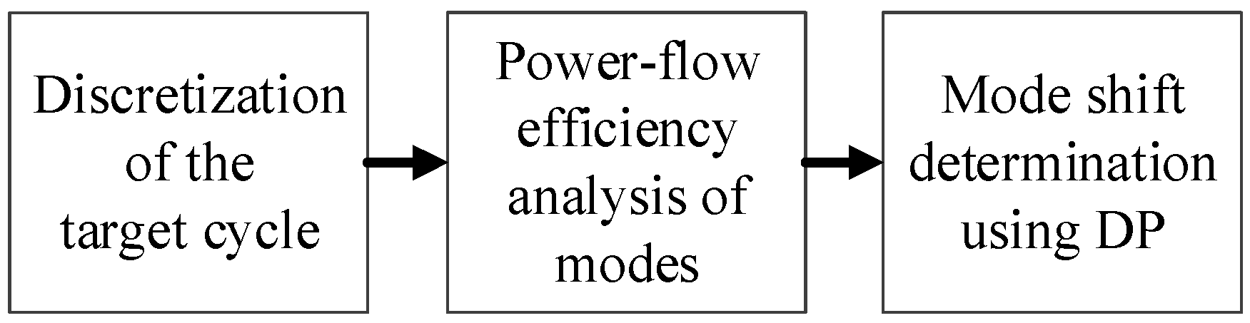
The process of the E-PEARS+ is presented in Figure 12. Details are laid out in the steps below.
Step 1: Discretization of the target cycle
The target cycle, such as straight driving or turning cycle, can be discretized into a four-dimensional table, namely, vehicle central speed, turning radius, torque demand of left track, and torque demand of right track. The table entries represent the probability of the cells appearing in the target cycle. Each cell has a determined value of central speed, radius, and torques (SRT), which will be called an SRT cell in the following steps.
In effect, given the central speed and turning radius, the speed of each side of track can be calculated as in Equation (25). is the central speed, and are the speeds of the left and right tracks. B is the track gauge and R is the turning radius. While straight driving, the speed of each track equals the central speed.
Step 2. Power-flow efficiency analysis of each mode
For each SRT cell, all possible torque and speed combinations of components for each mode will be examined to identify the control with the greatest efficiency. It should also be noted that since engine efficiency is much lower than that of the motor, power-flow efficiency will be normalized by their maximum efficiency. The power-flow of the multi-mode design can be seen in Figure 13.
Puc, Pe, and Poutputs are the power of the ultracapacitor pack, engine, and outputs. Pmg is the motor power, which comes from or goes into the mechanical flow; Pmg_elec is the motor power, which comes from or goes into the electrical flow; , , and are the maximum operating efficiency of the ultracapacitor pack, engine, and motors.
When the engine is not connected to the powertrain, or the engine power equals zero, the system works in pure electric mode. Efficiency is calculated considering power loss, as in Equation (26). is the energy storage system loss and motor loss. The highest efficiency of each mode is calculated together with the motor operations.
Normalized efficiency for the hybrid mode is calculated as in Equation (27). For hybrid driving states, the energy sources are the ultracapacitor pack and engine. The output power of the engine and the ultracapacitor pack are normalized by maximum operating efficiency, and motor power loss is also subtracted to obtain effective normalized system power. When the ultracapacitor is charged, energy derives solely from the engine.
Step 3: Optimal mode shift using DP
Once the control executions of each SRT for all modes are determined in Step 2, the next step is to determine the mode shift during drive cycles [31]. Dynamic programming is used to obtain optimal mode shift and to ensure the state of charge (SOC) sustaining. The states and controls of DP are shown in Table 4. The first state is the state of charge (SOC), which is calculated in Step 2. The second state is the current mode and the control is the mode of the next segment. Mode is included in the states as the cost function has the mode shift penalty. The cost function and constraint of this problem are explained in Equation (28).
subject to:
where is the penalty to ensure that the final state of SOC is close to the desired value; is the penalty of speed difference to avoid frequent mode switching; L is the fuel consumption of each segment. The mode shift penalty is included to ensure smooth mode shift.
Since the dimension of the DP problem is rather low, it takes less than 10 s to determine the mode-shift results of a 50 s cycle. Once the mode shift is determined for the cycle, the control executions can be obtained. The E-PEARS+ has near-optimal control effects compared with DP, with a more than 100 times increase in computation speed.
5. Integrated Optimization of Multi-Mode Hybrid Electric TTDS
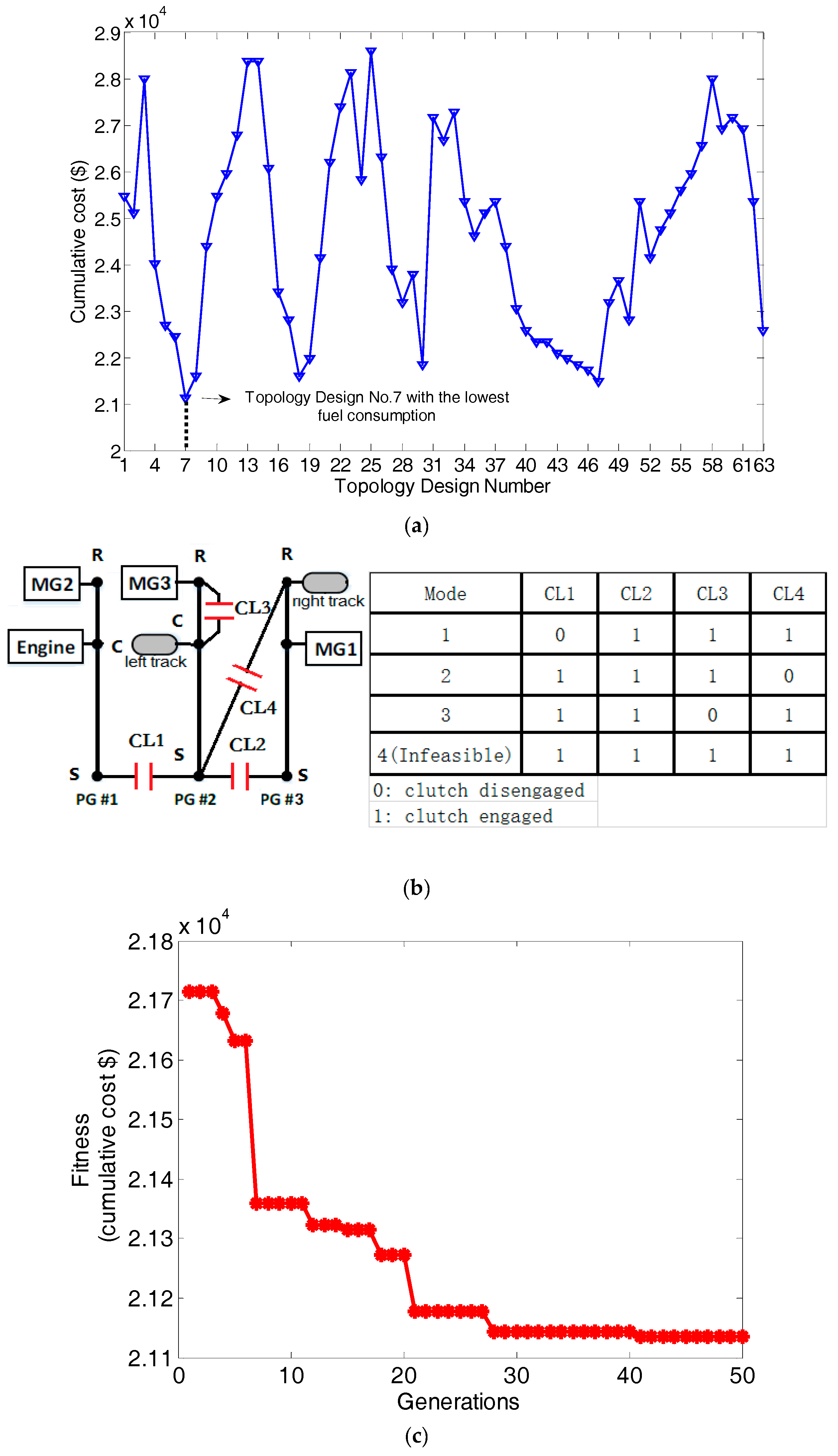
With the rapid energy management strategy E-PEARS+, the surviving designs will be further optimized taking into account different size parameters. Fuel economy, together with cost, is selected as the objective under the performance constraints. All surviving 63 designs are calculated with different sizes of powertrain to identify the final optimal design. The integrated optimization adopts nested optimization [32] using chaos-enhanced accelerated particle swarm optimization (CAPSO) [23]. Details are shown in Figure 14.
The CAPSO is modified by logistic map, which appears in nonlinear dynamics of biological population demonstrating chaotic behavior. CAPSO can enhance the chaos stability by randomly accepting a worse solution that can help the algorithm to escape from the local optima. The particle position updates together with the logistic map for CAPSO is shown in Equations (30) and (31):
where is the best position of the ith iteration, is the convergence parameter, and is the attraction parameter, which changes with the logistic map. In this paper, the initial values of , , , and are 0.9, 0.9, 0.7, and 4.
Size parameters that need to be optimized include the final drive of the left and right tracks (FL and FR), the gear ratios of three PGs (GR1, GR2, and GR3), and the power scaling factor of the engine and three motors (SE, SMG1, SMG2, SMG3).
To compare the novel design with the current powertrain in terms of cost, the cumulative cost, including power electronic cost and one-year fuel cost of use, is selected as the single objective. For each candidate, the fuel economy is calculated using E-PEARS+ and the one-year fuel cost can be estimated. Performances are selected as the constraints, and must be better than those of the series hybrid benchmark. The optimization problem is formulated in Equations (32)–(33):
subject to:
The cost of the power electronics consists of engine cost, motor cost, ultracapacitor pack cost, and 3PG set cost, as shown in Equation (34). The component costs estimation method is from EPRI and several studies [33,34,35].
where is the engine cost, is the motor cost, is the ultracapacitor pack cost, and is the planetary gear set cost; and are the power of the engine and motor, respectively; is the module number of the ultracapacitor pack; and is the planetary gear number of the transmission.
The fuel consumption varies in different speed and torque. Since it is hard to precisely evaluate average fuel economy during real-time driving, the one-year fuel cost is estimated based on the two typical cycles in Figure 12. Assuming that the TTD works four hours per day and 150 days per year, the total fuel cost can be calculated as in Equation (35).
where is the unit price of diesel oil; and are the total cycle time of the typical straight and turning cycle, respectively; and and are the total fuel consumption during straight driving and turning cycles, respectively.
With E-PEARS+ and the integrated optimization using CAPSO, the process can be 1000 times faster than with the existing methodology. After the optimization of all 63 surviving designs as shown in Figure 15, topology design No. 7 is proven to have the best result. The lever diagram [36] is presented in Figure 15 together with the size optimization result. The final optimized size parameters of the optimal design are shown in Equation (36):
To show the advantages of the proposed novel powertrain, the performance, fuel economy, and cost are compared with the current series benchmark.
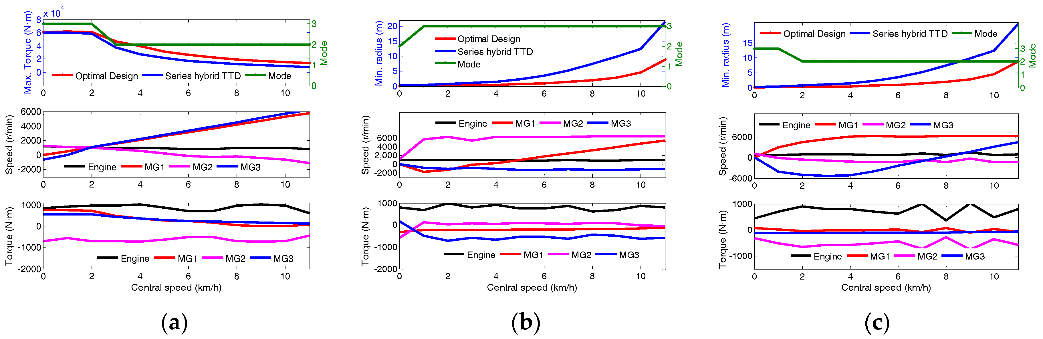
The maximum towing capacity and minimum turning radius at all speeds of the final design and the series benchmark are shown in Figure 16. The average towing capacity and turning capacity of the proposed optimal design are about 25% and 44% better than the current series hybrid powertrain.
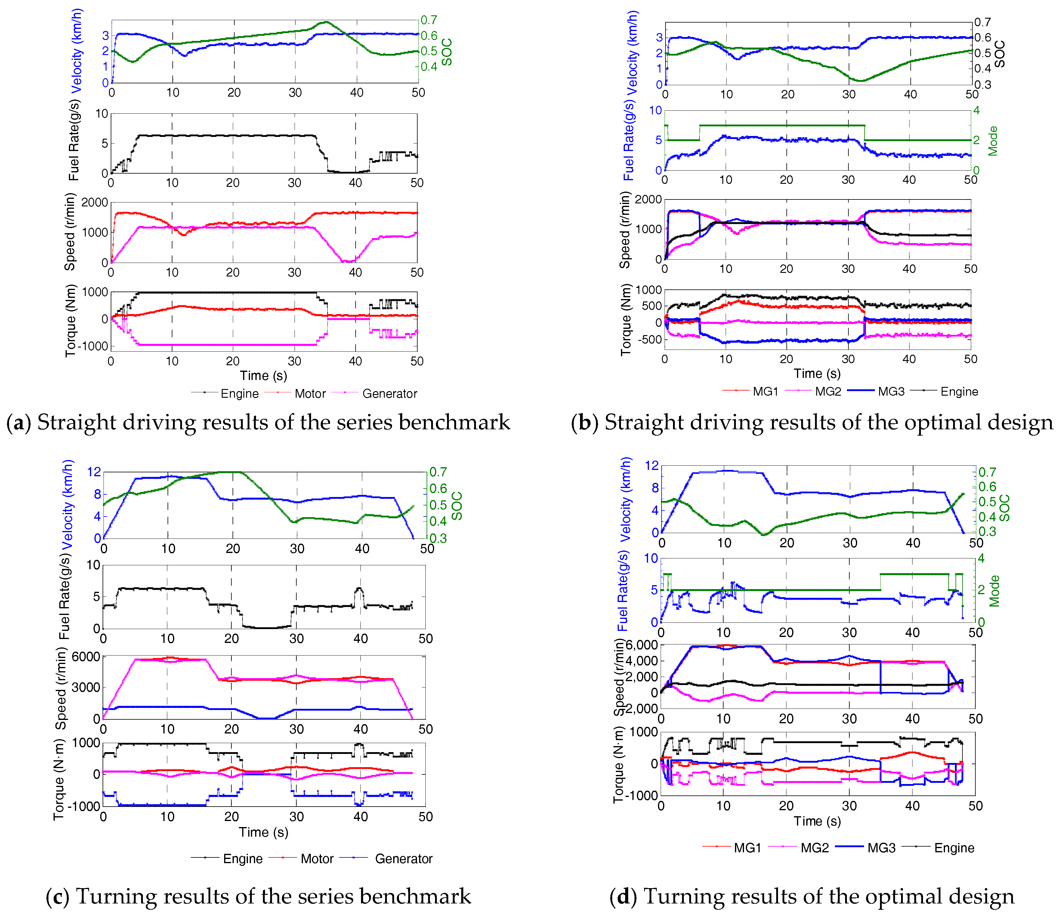
The E-PEARS+ control results under two typical cycles for the final design and series benchmark are shown in Figure 17. The fuel consumption of the series hybrid TTD under the straight driving and turning cycles are 221.9 g and 183.7 g, respectively, while those of the final design are 192.1 g and 146.1 g. The fuel economy of our design reflects a 13.5% and 21% improvement over the series hybrid benchmark.
To further explain the cumulative cost of our design and the series benchmark, the cost corresponding to years of ownership is calculated. The power electronics of the series hybrid cost approximately 14,100 $, which is a bit cheaper than the 14,600 $ of our design due to the 3PG set. As the fuel economy of our design is much better than the series hybrid TTD, however, the cumulative cost of our design will be lower than that of the series hybrid after only 0.53 years of use. Moreover, as time goes on, our design will become increasingly cost-effective, an important advantage in industrial applications.
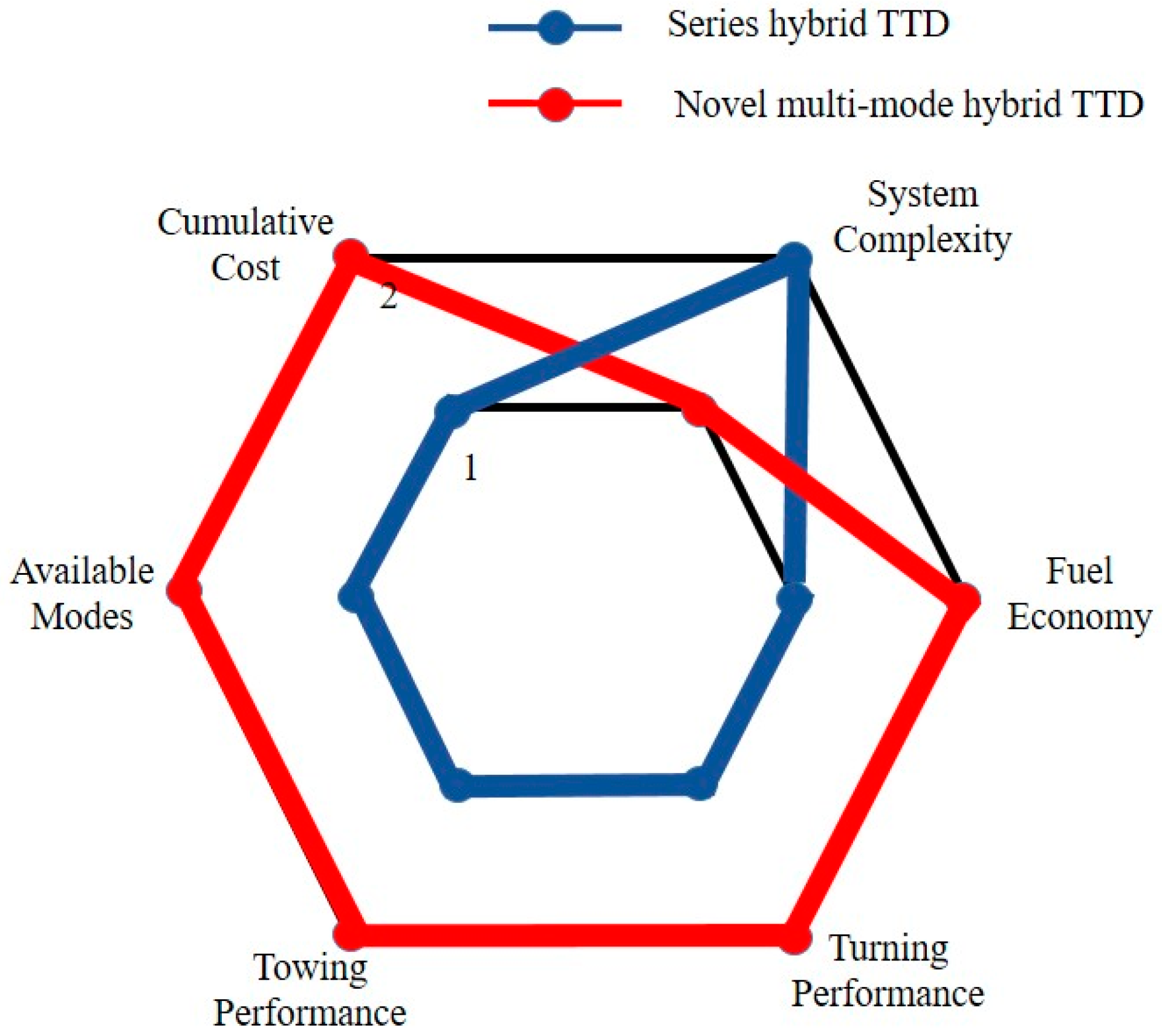
To conclude, a radar diagram is shown in Figure 18 to compare our multi-mode powertrain with the series hybrid benchmark: 1 represents an inferior level of advantages for the features and 2 represents a superior level. It can be seen that the series hybrid powertrain is more compact and easier to produce, while the novel multi-mode powertrain is more complex because of the 3PG set. The proposed multi-mode powertrain, however, is better in other regards. Thus, we believe that as the manufacturing technology of PGs for tracked vehicles becomes more advanced in the future, the proposed novel multi-mode powertrain of tracked vehicles will become more promising and suitable for industrial applications.
6. Conclusions
In this paper, a novel multi-mode hybrid electric powertrain for tracked vehicles is proposed. A practical applied series hybrid TTD is selected as the benchmark. We first analyze the configuration and design generation process to reduce the large design pool to a manageable size. By rapid automated modeling of all candidate designs, attributes and drivability are used to obtain superior designs. Subsequently, by establishing E-PEARS+, the fuel economy of straight driving and turning for TTDs can be evaluated. Surviving topology designs are optimized together with size parameters integrally. The final optimal design shows both better drivability and better fuel economy during straight driving and turning. The design is also more economical, showing good developmental potential for future practical applications.
It should also be noted that, apart from tracked vehicles, the proposed design method is also useful for multi-PG powertrain analysis of hybrid passenger cars or light trucks. The design generation process, the automated modeling, and the integrated optimization can help engineers locate the optimal design accurately and efficiently.
Acknowledgments
The authors appreciate the financial support of the National Key R&D Program (2016YFB0100905) and the National Natural Science Foundation of China (51575295).
Author Contributions
Zhaobo Qin proposed the novel design and the optimization framework; Yugong Luo, Keqiang Li, and Huei Peng provided guidance and key suggestions.
Conflicts of Interest
The authors declare no conflict of interest.
Nomenclature
| A* | characteristic matrix |
| c | constraint number |
| C* | cost of components |
| unit price of per gallon | |
| Fstraight | fuel consumption during straight driving |
| Fturn | fuel consumption during turning |
| F* | internal force of PGs acting between gears |
| FR | final drive of the right track |
| FL | final drive of the left track |
| GR | gear ratio of PGs |
| I* | inertia of the components |
| m | vehicle mass |
| n | planetary gear number |
| P* | power of the components |
| r* | radius of the ring gear |
| S* | scaling factor of components |
| s* | radius of the sun gear |
| T* | torque of the components |
| Vl | speed of the left track |
| Vr | speed of the right track |
| V | central speed |
| convergence parameter | |
| attraction parameter | |
| angular acceleration of the components | |
| operating efficiency of the components | |
| Acronyms | |
| DOF | Degree of Freedom |
| DP | Dynamic Programming |
| GA | Genetic Algorithm |
| MPC | Model Predictive Control |
| NSGA | Non-dominated Sorting Genetic Algorithm |
| PG | Planetary Gear |
| PSO | Particle Swarm Optimization |
| SOC | State of Charge |
| TTD | Track-type Dozer |
| ECMS | Equivalent Consumption Minimization Strategy |
| PEARS | Power-weighted Efficiency Analysis for Rapid Sizing |
References
- Wang, H.; Liu, L.; Zheng, G. Study of Two-Motor Hybrid Bulldozer; SAE Technical Paper; SAE International: Warrendale, PA, USA, 2014. [Google Scholar]
- Gordon, T.D.; Tkacik, D.S.; Presto, A.A.; Zhang, M.; Jathar, S.H.; Nguyen, N.T.; Massetti, J.; Truong, T.; Cicero-Fernandez, P.; Maddox, C.; et al. Primary gas-and particle-phase emissions and secondary organic aerosol production from gasoline and diesel off-road engines. Environ. Sci. Technol. 2013, 47, 14137–14146. [Google Scholar] [CrossRef] [PubMed]
- Sangshin, K.; Kim, T.; Park, G. Phase-redundant-based reliable direct AC/AC converter drive for series hybrid off-highway heavy electric vehicles. IEEE Trans. Veh. Technol. 2010, 59, 2674–2688. [Google Scholar] [CrossRef]
- Wang, J.; Yang, Z.; Liu, S.; Zhang, Q.; Han, Y. A comprehensive overview of hybrid construction machinery. Adv. Mech. Eng. 2016, 8. [Google Scholar] [CrossRef]
- Mehrdad, E.; Gao, Y.; Gay, S. Characterization of electric motor drives for traction applications. In Proceedings of the 29th Annual Conference of the IEEE Industrial Electronics Society, Roanoke, VA, USA, 2–6 November 2003; IEEE: Piscataway, NJ, USA, 2003; Volume 1. [Google Scholar]
- Wang, H.; Huang, Y.; Khajepour, A.; Song, Q. Model predictive control-based energy management strategy for a series hybrid electric tracked vehicle. Appl. Energy 2016, 182, 105–114. [Google Scholar] [CrossRef]
- Wang, H.; Huang, Y.; Lv, C.; Khajepour, A. A Global Optimal Energy Management System for Hybrid Electric off-road Vehicles. SAE Int. J. Commer. Veh. 2017, 10, 524–531. [Google Scholar]
- Liu, T.; Zou, Y.; Liu, D.; Sun, F. Reinforcement learning of adaptive energy management with transition probability for a hybrid electric tracked vehicle. IEEE Trans. Ind. Electron. 2015, 62, 7837–7846. [Google Scholar] [CrossRef]
- Schmidt, M.R. Two-Mode, Compound-Split, Electro-Mechanical, Vehicular Transmission Particulary Adapted for Track-Laying Vehicles. U.S. Patent 6,491,599, 10 December 2002. [Google Scholar]
- Shabana, A.A. Nonlinear Dynamics of Tracked Vehicles; Chicago University: Chicago, IL, USA, 1997. [Google Scholar]
- Han, Z.; Mao, M.; Ma, X.; Gai, J. Research no mathematical characteristics of coupling mechanism for electro-mechanical transmission tracked vehicle. Veh. Power Technol. 2012, 125, 1–2. [Google Scholar]
- Tanoue, K.; Yanagihara, H.; Kusumi, H. Hybrid is a Key Technology for Future Automobiles. In Hydrogen Technology; Springer: Berlin, Germany, 2008; ISBN 978-3-540-79027-3. [Google Scholar]
- Matthé, R.; Eberle, U. The Voltec System-Energy Storage and Electric Propulsion. In Lithium-Ion Batteries: Advances and Applications; Elsevier: Amsterdam, The Netherlands, 2014; pp. 151–176. ISBN 9780444595133. [Google Scholar]
- Zhuang, W.; Zhang, X.; Peng, H.; Wang, L. Simultaneous Optimization of Topology and Component Sizes for Double Planetary Gear Hybrid Powertrains. Energies 2016, 9, 411. [Google Scholar]
- Yoshimura, T. Vehicle Power Transmission. U.S. Patent 8,535,189 B2, 17 September 2013. [Google Scholar]
- Silvas, E.; Hofman, T.; Murgovski, N. Review of optimization strategies for system-level design in hybrid electric vehicles. IEEE Trans. Veh. Technol. 2017, 66, 57–70. [Google Scholar] [CrossRef]
- Liu, J.; Peng, H. Modeling and control of a power-split hybrid vehicle. IEEE Trans. Control Syst. Technol. 2008, 16, 1242–1251. [Google Scholar]
- Zhang, X.; Li, S.E.; Peng, H. Efficient exhaustive search of power-split hybrid powertrains with multiple planetary gears and clutches. J. Dyn. Syst. Meas. Control 2015, 137, 121006. [Google Scholar] [CrossRef]
- Wang, X.; He, H.; Sun, F.; Tang, H. Comparative study on different energy management strategies for plug-in hybrid electric vehicles. Energies 2013, 6, 5656–5675. [Google Scholar] [CrossRef]
- Johannesson, L.; Asbogard, M.; Egardt, B. Assessing the potential of predictive control for hybrid vehicle powertrains using stochastic dynamic programming. IEEE Trans. Intell. Transp. Syst. 2007, 8, 71–83. [Google Scholar] [CrossRef]
- Musardo, C.; Rizzoni, G.; Guezennec, Y. A-ECMS: An adaptive algorithm for hybrid electric vehicle energy management. Eur. J. Control 2005, 11, 509–524. [Google Scholar] [CrossRef]
- Fang, L.C.; Qin, S.Y.; Xu, G.; Li, T.L.; Zhu, K.M. Simultaneous optimization for hybrid electric vehicle parameters based on multi-objective genetic algorithms. Energies 2011, 4, 532–544. [Google Scholar] [CrossRef]
- Ebbesen, S.; Doenitz, C.; Guzzella, L. Particle swarm optimisation for hybrid electric drive-train sizing. Int. J. Veh. Des. 2012, 58, 181–199. [Google Scholar] [CrossRef]
- Wu, L.H.; Wang, Y.N.; Yuan, X.F.; Chen, Z.L. Multiobjective optimization of HEV fuel economy and emissions using the self-adaptive differential evolution algorithm. IEEE Trans. Veh. Technol. 2011, 60, 2458–2470. [Google Scholar] [CrossRef]
- Castaings, A.; Lhomme, W.; Trigui, R.; Bouscayrol, A. Comparison of energy management strategies of a battery/supercapacitors system for electric vehicleunder real-time constraints. Appl. Energy 2016, 163, 190–200. [Google Scholar] [CrossRef]
- Zhang, L.; Hu, X.; Wang, Z.; Sun, F.; Deng, J.; Dorrell, D. Multi-Objective Optimal Sizing of Hybrid Energy Storage System for Electric Vehicles. IEEE Trans. Veh. Technol. 2017. [Google Scholar] [CrossRef]
- Rahman, I.; Vasant, P.M.; Singh, B.S.M.; Abdullah-Al-Wadud, M. On the performance of accelerated particle swarm optimization for charging plug-in hybrid electric vehicles. Alex. Eng. J. 2016, 55, 419–426. [Google Scholar] [CrossRef]
- Luo, Y.-Z.; Tang, G.-J.; Zhou, L.-N. Hybrid approach for solving systems of nonlinear equations using chaos optimization and quasi-Newton method. Appl. Soft Comput. 2008, 8, 1068–1073. [Google Scholar] [CrossRef]
- Zhou, Q.; Zhang, W.; Cash, S.; Olatunbosun, O.; Xu, H.; Lu, G. Intelligent sizing of a series hybrid electric power-train system based on Chaos-enhanced accelerated particle swarm optimization. Appl. Energy 2017, 189, 588–601. [Google Scholar] [CrossRef]
- Liu, J. Modeling, Configuration and Control Optimization of Power-Split Hybrid Vehicles; The University of Michigan: Ann Arbor, MI, USA, 2007. [Google Scholar]
- Hong, S.; Choi, W.; Ahn, S. Mode shift control for a dual-mode power-split-type hybrid electric vehicle. Proc. Inst. Mech. Eng. Part D J. Automob. Eng. 2014, 228, 1217–1231. [Google Scholar] [CrossRef]
- Sergeyev, Y.D.; Grishagin, V.A. Parallel asynchronous global search and the nested optimization scheme. J. Comput. Anal. Appl. 2010, 3, 123–145. [Google Scholar]
- Golbuff, S. Optimization of a Plug-in Hybrid Electric Vehicle. Master’s Thesis, Georgia Institute of Technology, Atlanta, GA, USA.
- Graham, R. Comparing the Benefits and Impacts of Hybrid Electric Vehicle Options; Electric Power Research Institute (EPRI): Palo Alto, CA, USA, 2001. [Google Scholar]
- Hu, X.; Murgovski, N.; Johannesson, L.M. Comparison of three electrochemical energy buffers applied to a hybrid bus powertrain with simultaneous optimal sizing and energy management. IEEE Trans. Intell. Transp. Syst. 2014, 15, 1193–1205. [Google Scholar] [CrossRef]
- Benford, H.; Leising, M. The Lever Analogy: A New Tool in Transmission Analysis; SAE Paper 810102; SAE International: Warrendale, PA, USA, 1981. [Google Scholar]
Figure 1.
Schematic diagram of the proposed powertrain.
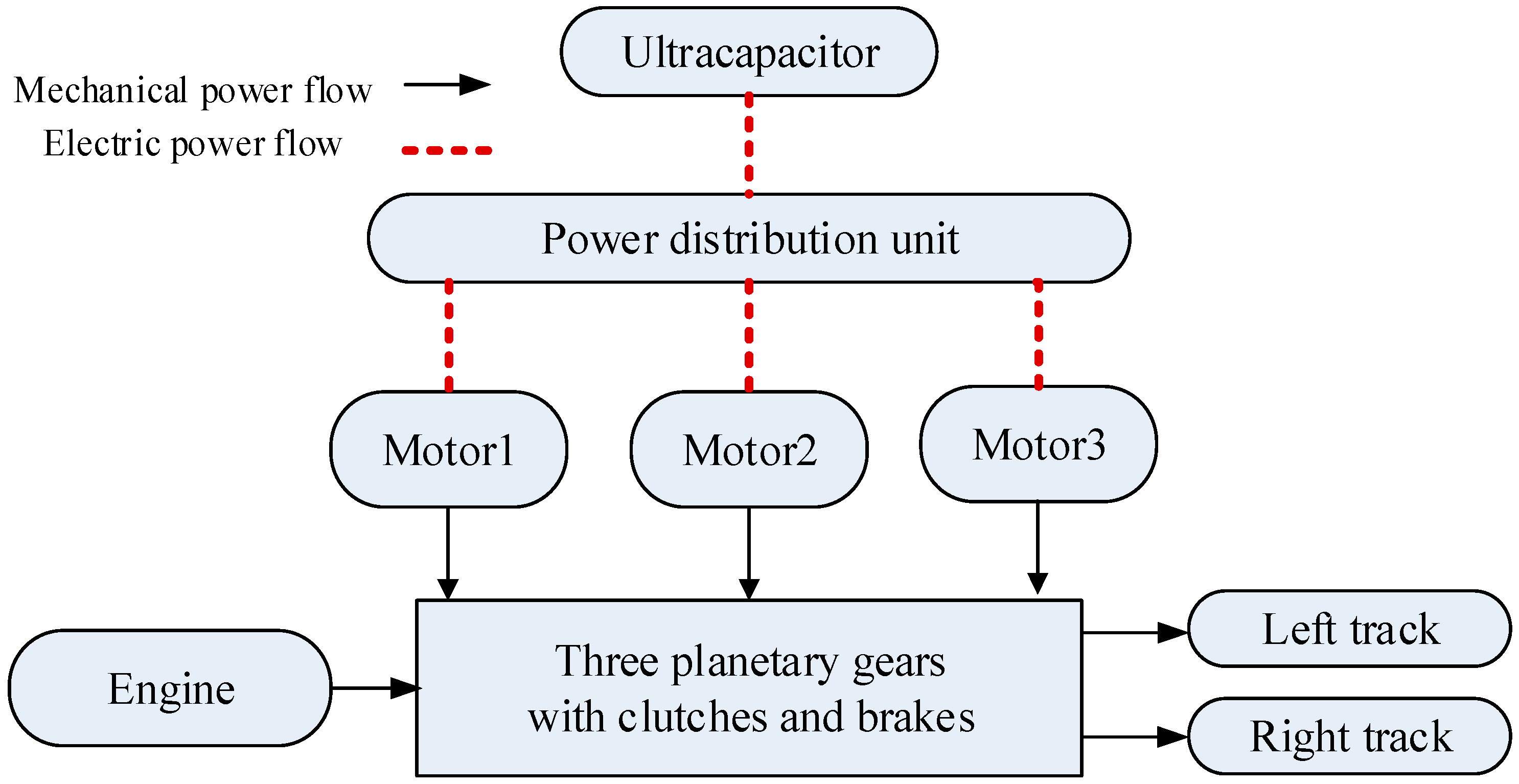
Figure 2.
Configuration, design, and mode generation process.

Figure 3.
All types of constraints for the 3-PG (planetary gear) set.

Figure 4.
The systematic optimization procedure.
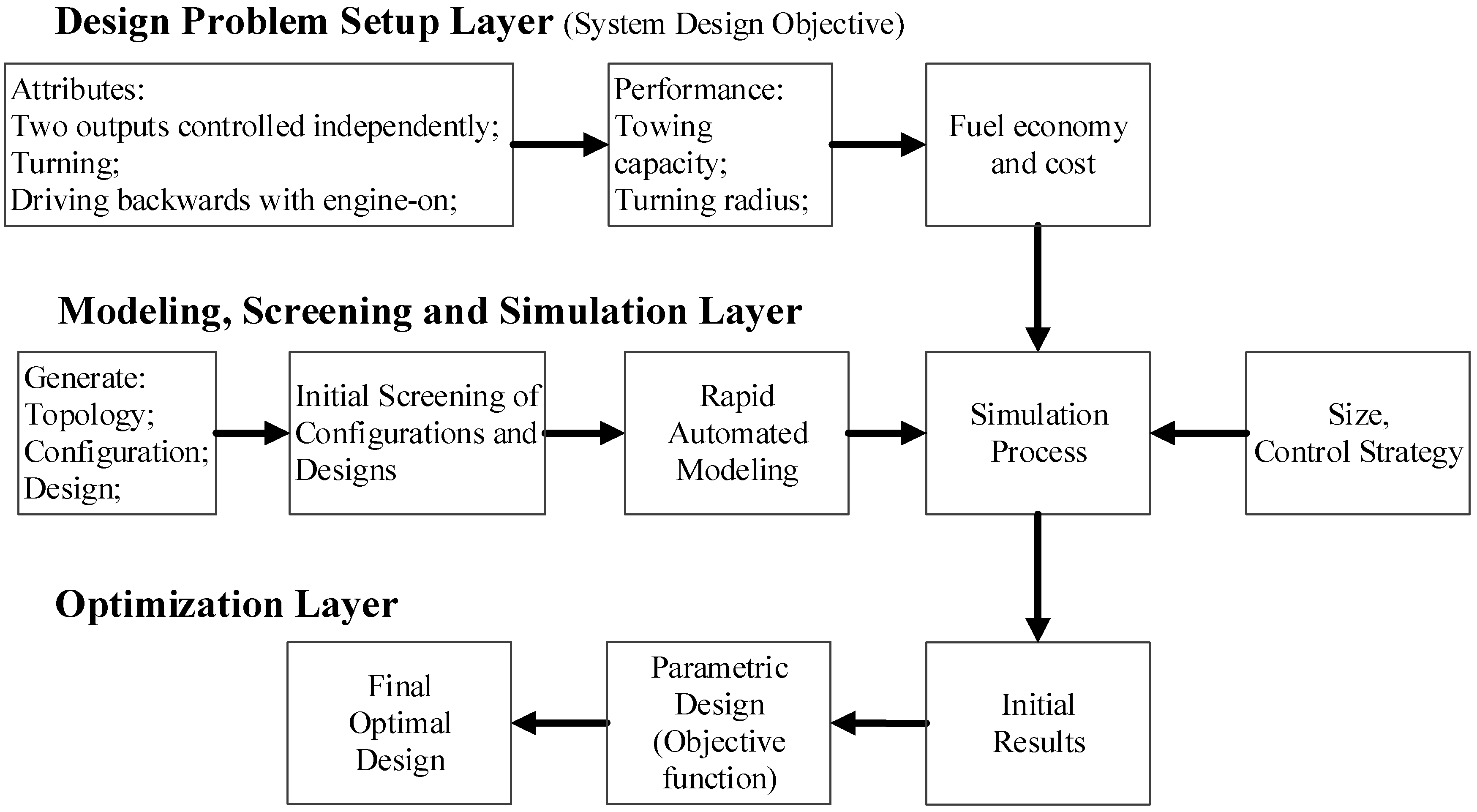
Figure 5.
Speed relationship when engine, output, and motor are connected in one PG. (a) engine at the ring gear, output at the carrier gear, motor at the sun gear; (b) engine at the carrier gear, output at the ring gear, motor at the sun gear; (c) engine at the sun gear, output at the carrier gear, motor at the ring gear; (d) engine at the carrier gear, output at the sun gear, motor at the ring gear; (e) engine at the ring gear, output at the sun gear, motor at the carrier gear; (f) engine at the sun gear, output at the ring gear, motor at the carrier gear.
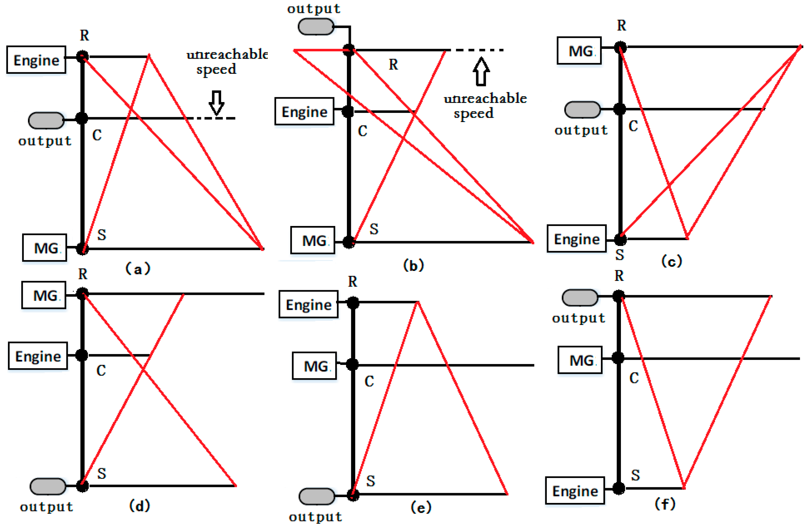
Figure 6.
Maximum output torque analysis. (a) Max. output torque in Figure 5c; (b) Max. output torque in Figure 5d; (c) Max. output torque in Figure 5e; (d) Max. output torque in Figure 5f.
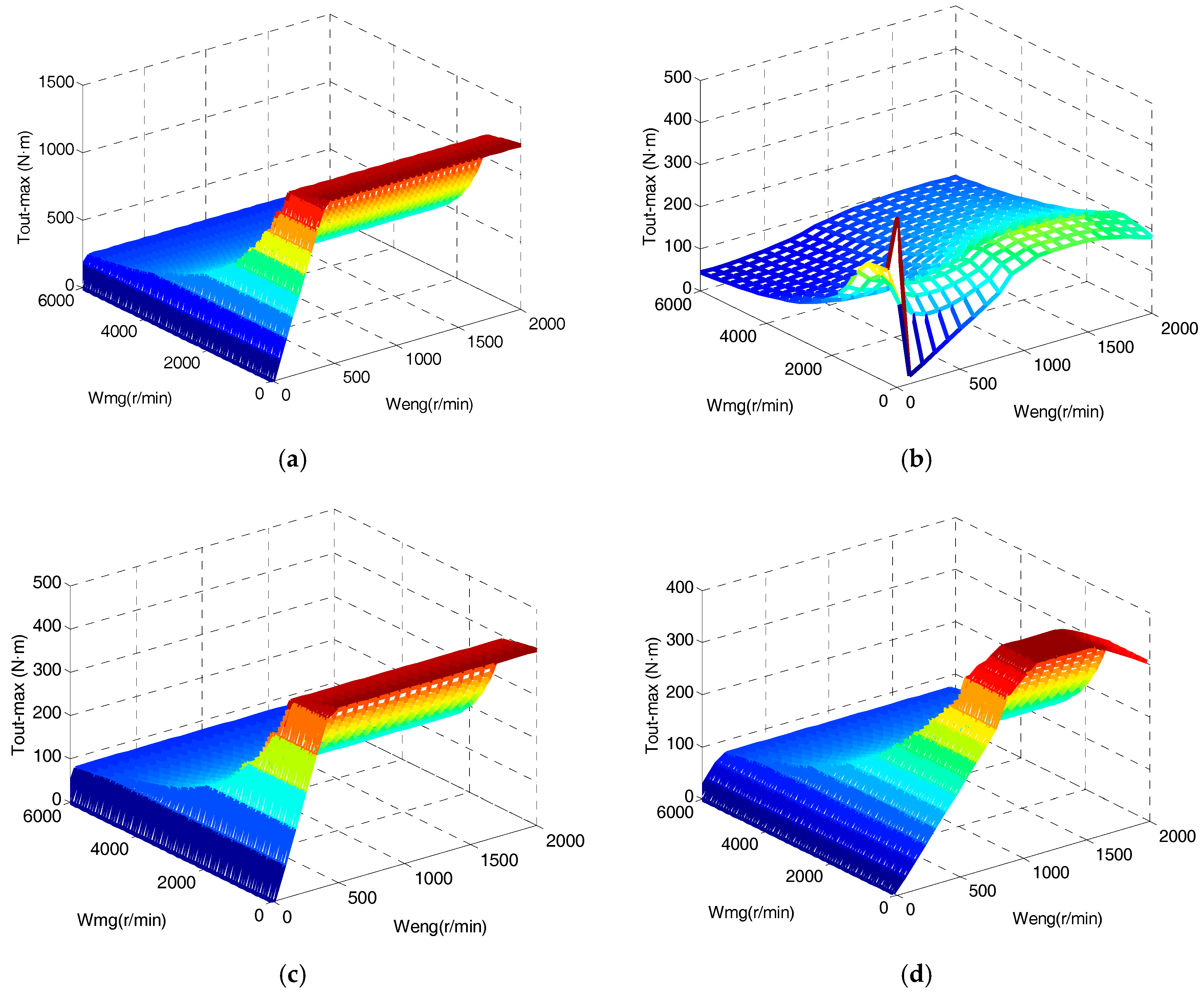
Figure 7.
Forty superior configurations after speed and torque analysis.

Figure 8.
Maximum traction torque distribution of all surviving designs.

Figure 9.
Examples of two designs with identical dynamic characteristics. (a) One candidate design; (b) another candidate design with different clutch locations.
Figure 9.
Examples of two designs with identical dynamic characteristics. (a) One candidate design; (b) another candidate design with different clutch locations.

Figure 10.
Straight driving and turning performance screening.
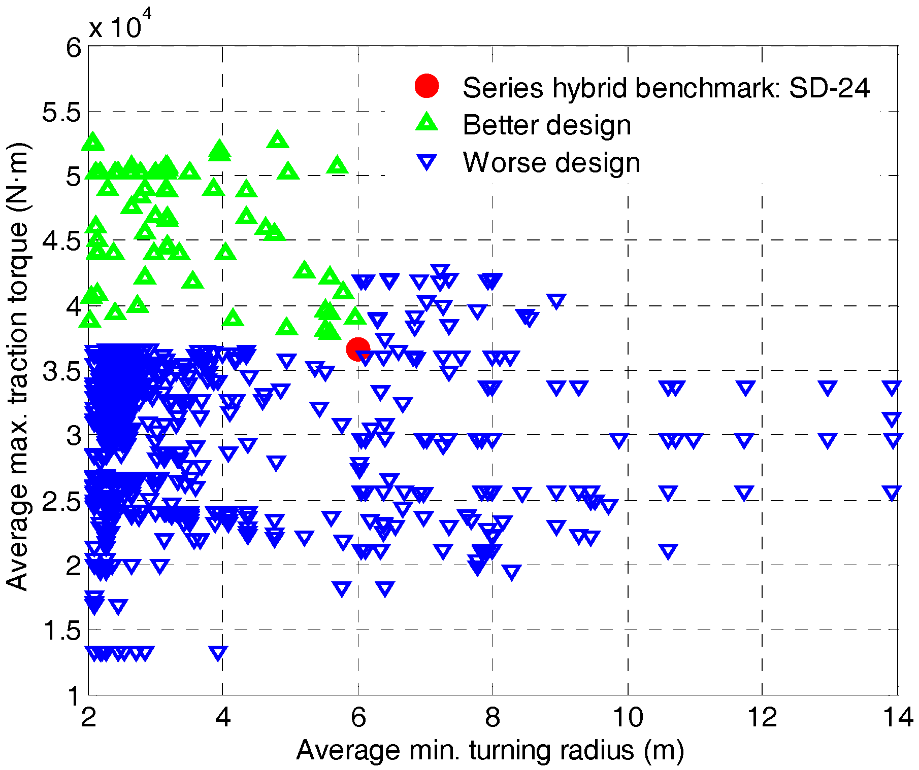
Figure 11.
Driving cycles: (a) straight driving cycle; (b) turning cycle.
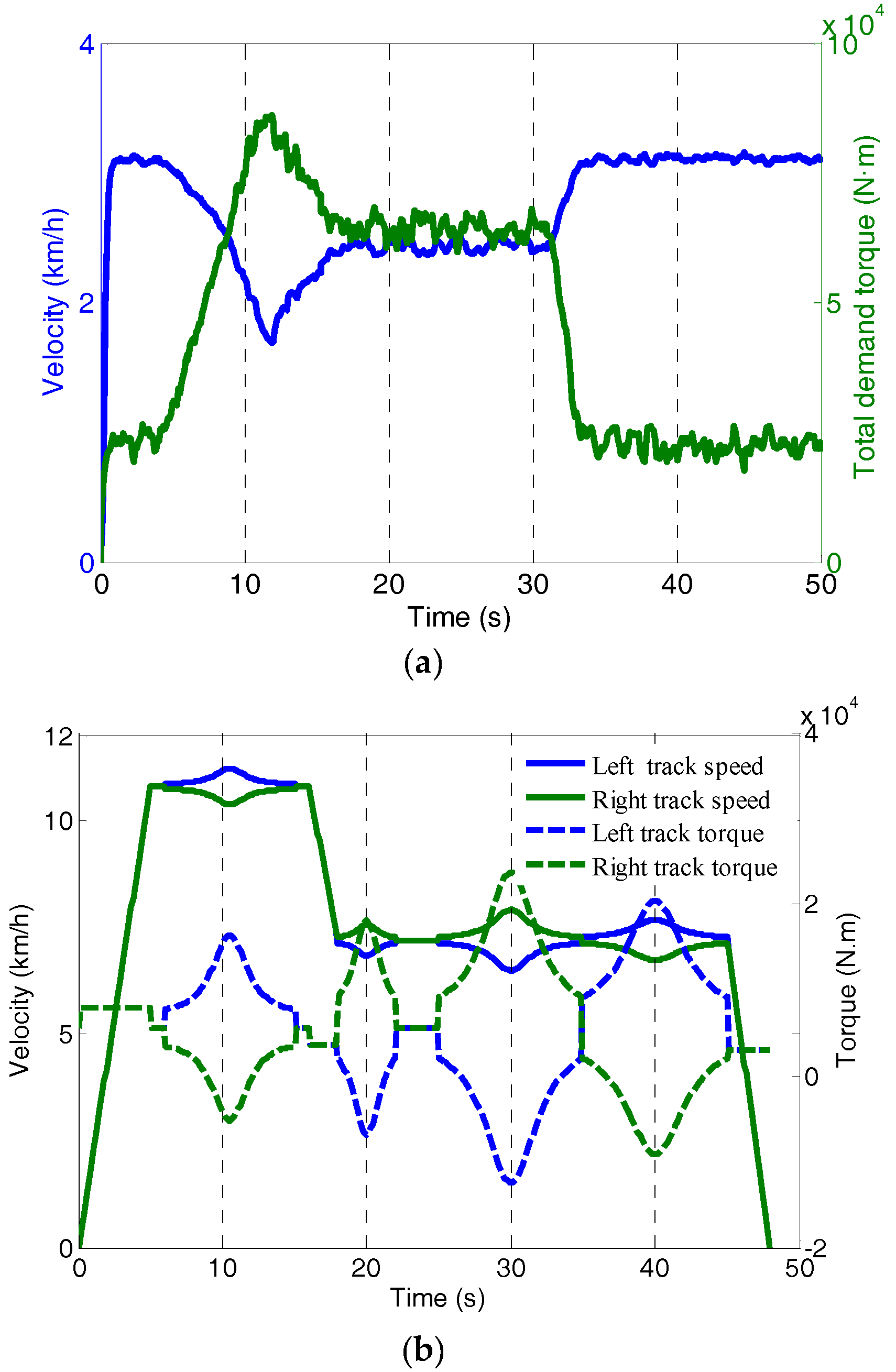
Figure 12.
Enhanced power-weighted efficiency analysis for rapid sizing (E-PEARS+) process.

Figure 13.
Power flow in the powertrain.
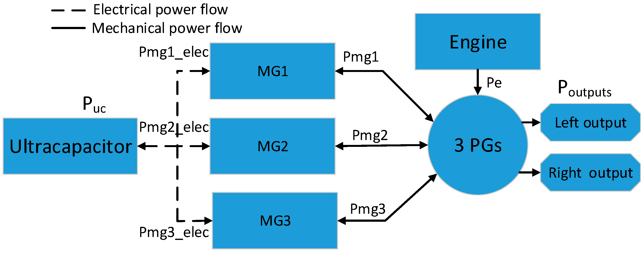
Figure 14.
Integrated optimization procedure.
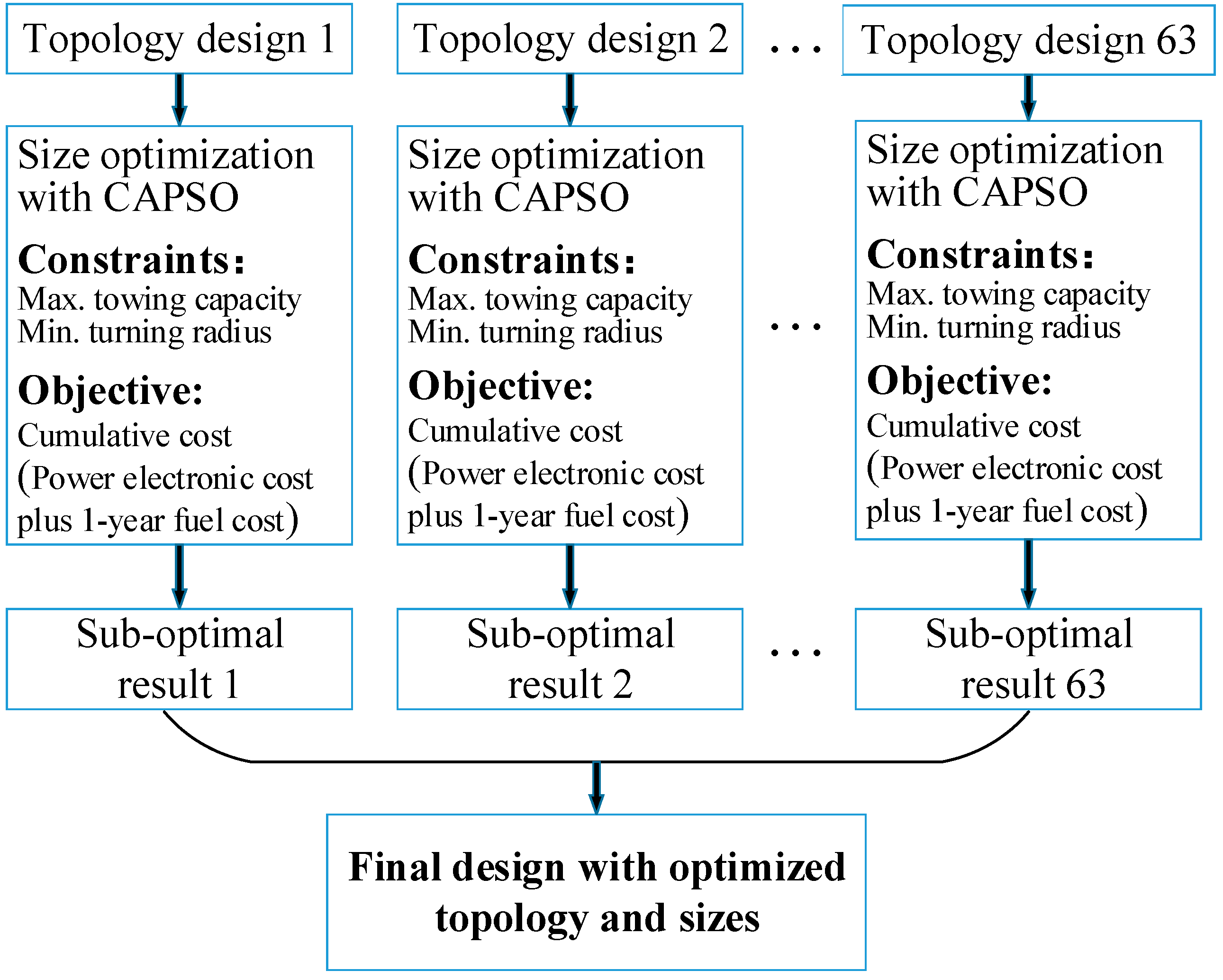
Figure 15.
Optimization result: (a) results of all topologies, (b) lever diagram of the final design, (c) size optimization result of the final design.
Figure 15.
Optimization result: (a) results of all topologies, (b) lever diagram of the final design, (c) size optimization result of the final design.

Figure 16.
Performance of the final optimal design: (a) straight driving, (b) left turning, (c) right turning.
Figure 16.
Performance of the final optimal design: (a) straight driving, (b) left turning, (c) right turning.

Figure 17.
Control results comparison under typical cycles.

Figure 18.
Radar map comparison of the novel multi-mode hybrid track-type dozer (TTD) and series hybrid TTD.
Figure 18.
Radar map comparison of the novel multi-mode hybrid track-type dozer (TTD) and series hybrid TTD.


Table 1.
Key parameters of the benchmark track-type dozer (TTD).
| Parameter | Value | |
|---|---|---|
| Vehicle | Vehicle mass (kg) | 28,000 |
| Track length (m) | 3.05 | |
| Track gauge (m) | 1.786 | |
| Diesel Engine | Rated speed (r/min) | 1700 |
| Rated power (kW) | 175 | |
| Generator | Max. power (kW) | 180 |
| Max. rotational speed (r/min) | 2200 | |
| Motors | Rated Power (kW) | 75 |
| Max. rotational speed (rpm) | 6000 | |
| Ultracapacitor | Capacity (F) | 2.4 |
| Voltage (V) | 600 |
Table 2.
Types of feasible connections in one planetary gear (PG) of a configuration.
| Type No. | Components Connected in One PG |
|---|---|
| 1 | Engine, Output, Motor |
| 2 | Engine, Motor, Motor |
| 3 | Motor, Motor, Output |
| 4 | Engine, Motor |
| 5 | Engine, Output |
| 6 | Motor, Output |
| 7 | Motor, Motor |
Table 3.
Attribute screening conditions.
| Performance | Screening Conditions |
|---|---|
| Engine-on driving forwards | |
| Central Steering | |
| Engine-on driving backwards |
Table 4.
The states and controls of the dynamic programming (DP) problem.
| States and Controls | Description |
|---|---|
| State 1 | State of charge (battery energy consumption) |
| State 2 | Current mode |
| Control 1 | Next mode |
© 2017 by the authors. Licensee MDPI, Basel, Switzerland. This article is an open access article distributed under the terms and conditions of the Creative Commons Attribution (CC BY) license (http://creativecommons.org/licenses/by/4.0/).
Share and Cite
MDPI and ACS Style
Qin, Z.; Luo, Y.; Li, K.; Peng, H. Optimal Design of a Novel Hybrid Electric Powertrain for Tracked Vehicles. Energies 2017, 10, 2141. https://doi.org/10.3390/en10122141
AMA Style
Qin Z, Luo Y, Li K, Peng H. Optimal Design of a Novel Hybrid Electric Powertrain for Tracked Vehicles. Energies. 2017; 10(12):2141. https://doi.org/10.3390/en10122141
Chicago/Turabian StyleQin, Zhaobo, Yugong Luo, Keqiang Li, and Huei Peng. 2017. "Optimal Design of a Novel Hybrid Electric Powertrain for Tracked Vehicles" Energies 10, no. 12: 2141. https://doi.org/10.3390/en10122141
Note that from the first issue of 2016, this journal uses article numbers instead of page numbers. See further details here.