Article

An Improved Lubrication Model between Piston Rings and Cylinder Liners with Consideration of Liner Dynamic Deformations

1
Department of Vehicle Engineering, Taiyuan University of Technology, Taiyuan 030024, China
2
Centre for Efficiency and Performance Engineering, University of Huddersfield, Huddersfield HD1 3DH, UK
3
Shanxi Lu’an Taihang Lubricant Co., Ltd., Changzhi 046204, China
*
Author to whom correspondence should be addressed.
Energies 2017, 10(12), 2122; https://doi.org/10.3390/en10122122
Submission received: 16 October 2017 / Revised: 6 December 2017 / Accepted: 10 December 2017 / Published: 13 December 2017

Abstract

:
The friction pair of piston rings and cylinder liner is one of the most important friction couplings in an internal combustion engine. It influences engine efficiency and service life. Under the excitation of piston slaps, the dynamic deformation of cylinder liner is close to the surface roughness magnitudes, which can affect the friction and lubrication performance between the piston rings and cylinder assemblies. To investigate the potential influences of structural deformations to tribological behaviours of cylinder assemblies, the dynamic deformation of the inner surface due to pistons slaps is obtained by dynamic simulations, and then coupled into an improved lubrication model. Different from the traditional lubrication model which takes the pressure stress factor and shear stress factor to be constant, the model proposed in this paper calculated these factors in real time using numerical integration to achieve a more realistic simulation. Based on the improved piston rings and cylinder liner lubrication model, the minimum oil film thickness and friction force curves are obtained for an entire work cycle. It shows that the friction force obtained from the improved model manifests clear oscillations in each stoke, which is different from the smoothed profiles predicted traditionally. Moreover, the average amplitude of the friction forces also shows clear reduction.

1. Introduction

Parasitic losses account for nearly 20% of an internal combustion (IC) engine’s total losses. As one of the primary sources of friction in the engine, the compression rings are responsible for 4% to 5% of all losses in a typical diesel engine [1]. Research on modelling of cylinder liner and piston ring tribological behaviours has been developed for decades. In modelling oil film formation and distribution on the cylinder liners, the cylinder wall is often taken as being a perfect cylindrical surface by the majority of researchers [1,2,3]. These studies believe that the deformation of cylinder liner does not directly affect the formation and distribution of the oil film, and thus does not affect the friction and lubrication behaviours.
In fact, no cylinder liner is perfectly cylindrical or of nominal bore radius along its entire length. The liner distortion leads to loss of conformity between the piston rings and cylinder liner. As a result of liner deformation, the drop of piston ring follow-up performance can cause the uneven contact and increased friction [4]. Therefore, it is essential to quantitatively study the deformation of cylinder liners.
Chittenden and Priest [
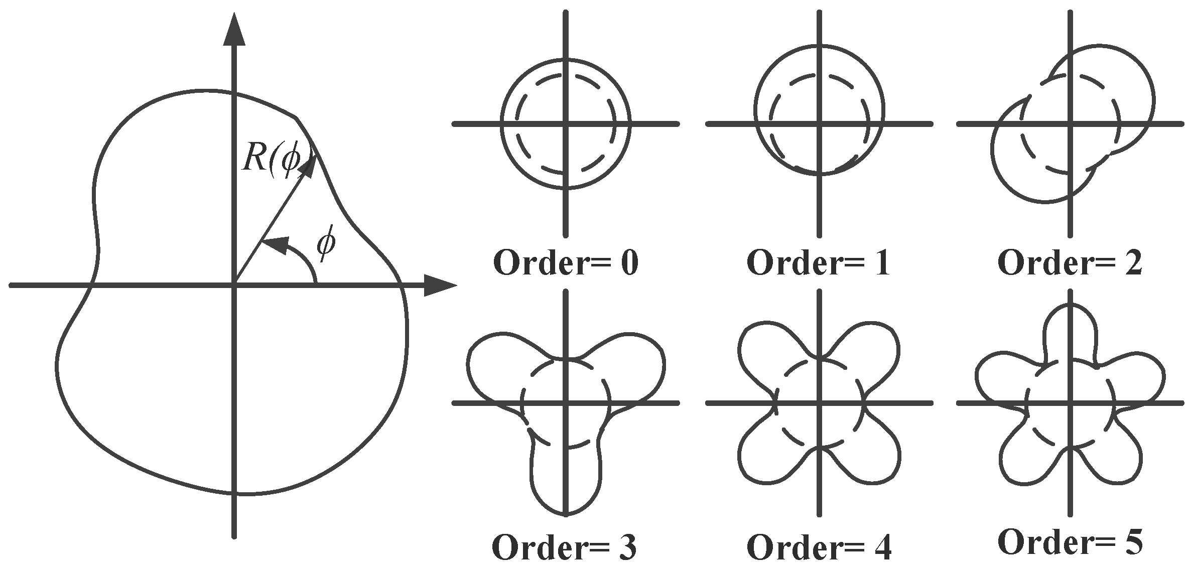
5] first proposed that the non-circularity of the engine cylinder liner can be represented by a Fourier series as Equation (1):
R ( ϕ ) = i = 0 i = n ( A i cos ϕ + B i sin ϕ )
where R ( ϕ ) = radial co-ordinate; ϕ = angular co-ordinate; Ai, Bi = amplitude constants; i = order; n = highest order distortion to be considered.
The coordinate system and various Fourier orders of liner distortion have been drawn in Figure 1. There are several reasons for the non-circularity of the cylinder liners. The machining precision of the cylinder liner is defined, or limited, within an allowed difference between the maximum and minimum diameters of the liner, which may be from 10 to 100 times the film thickness between piston rings and the liner. Thus, the nonconformity arising from machining tolerances is likely to impose a substantial effect on the friction characteristic of the piston–cylinder assembly. The zero-order and first-order liner distortions, as a function of the size and location tolerances of the cylinder liner [5], have been drawn in Figure 1. As these deformation components are circular, they have little consequence to conformity between piston rings and liners.
The assembly constraints of cylinder assembly can cause significant deformations in the liner. One typical case is the tightening of the cylinder head bolts. Chittenden and Priest pointed out that [5] the tightening of four cylinder head bolts is the main reason for the occurrence of the fourth-order distortion approximately 25 microns in a distorted cylinder liner of a light-duty engine.
Insufficient cooling or over-cooling of cylinder liner may lead to expansion deformations around the circumference of the cylinder and along its length, which leads to the distortion of the cylinder liners [5]. Reipert and Voigt [6] proposed that the magnitude of the thermal expansion is greater by far than the distortion caused by the clamping of cylinder head bolts. Zavos and Nikolakopoulos [3] have suggested that small thermal deformation will lead to less friction and wear in the cylinder liner. However, the thermal expansion is primarily a quasi-static deformation, with good radial continuity, which cannot cause obvious dynamic localised deformation on the liner surface, and therefore cannot cause direct impact on the friction and lubrication behaviour between piston rings and liner surface.
In addition to static deformations, the impulsive gas explosion and piston slaps can also cause evident distortion of the cylinder liner, although they only act on the liner wall within a restricted area. Furthermore, as Chittenden and Priest [5] pointed out, a significant deformation of the cylinder liner induced by combustion force can only be observed in those heavy-duty diesel engines with thin-walled wet liners. According to the simulation results obtained by Li and Gu [7,8,9], the amplitude of liner deformations induced by piston slaps is at the order of 0.1 microns, being about 20% of the roughness amplitude and able to affect the distribution of oil film and its subsequent lubrication performance.
To investigate the possible influence of liner deformations on friction and lubrication behaviours between piston and liners, several studies have been carried out. Ma et al. [10] studied the impacts of liner distortion on the friction forces between the piston rings and cylinder liners. Their simulation results showed that the distortion of the cylinder liner can considerably reduce friction loss by approximately 2% to 5%. Another study, conducted by Ali Usman et al. [11], pointed out that a distorted cylinder liner will decrease the viscous friction force of piston ring cylinder liner interface because the average film thickness between ring and distorted liner is much higher than that of circular liner. Meng et al. [12] further indicated that the vibration of the cylinder liner can result in oscillations in the dynamic and tribological performances of the piston assembly, especially in the power stroke of an IC engine. Their studies have shown that the vibration-induced friction reduction is closely related to the engine’s running speed, structural stiffness, and damping characteristics, and the mass of the cylinder structure. The experimental study conducted by Michael Gore et al. [13] strongly confirmed the existence of oscillations in the piston friction force through a direct measurement. Their work suggested that this kind of friction oscillation may be associated with a multitude of engine structural harmonics.
However, none these experimental and theoretical studies have provided more vigorous evidence or in-depth discussion on the mechanism behind the correspondence between the structural deformations and friction oscillations. Further research is therefore needed to determine the exact way in which liner deformations affect the friction forces.
To examine the influence mechanism of dynamic deformation on lubrication performance and friction losses of liner assembly based on a mathematical model, the first thing to do is to couple the dynamic deformation into the modelling of lubrication behaviours between piston rings and liners. When previous researchers tried to couple liner deformation into the lubrication model, only the influences of geometric deformations on asperity friction had been considered, in the form of a static geometric boundary. The changes in physical and chemical properties of lubricating oil caused by dynamic deformations and its subsequent effect on viscous friction between rings and liners has not been studied and understood deeply.
In 1979, Patir and Cheng [14] introduced pressure and shear flow factors to analyse surface roughness effects on mean hydrodynamic load and mean viscous friction. These factors make the effect of surface morphology on the viscous friction of lubricant quantified, thus promoting a series of follow-up studies. However, these factors are proposed based on an important assumption: the matching surface should be a Gaussian random rough surface. That is, the flow factors are equal and constant throughout the surface, and when considering the dynamic deformation of the cylinder liner, the surface roughness may exhibit non-Gaussian distribution. The local shear stress varies with the area, which requires a specific localized calculation of the two flow factors for the matching surfaces of ring and liner, to obtain a more accurate calculation of the viscous force. To investigate the effect of surface finish on piston ring-pack performance, Jeffrey Jocsak [15] proposed an integral calculation method of stress factors that makes it possible to consider the influence of non-Gaussian surface morphology on viscous friction forces.
To examine the influences of dynamic deformation on lubrication performance and the friction losses of liners, this paper improves the existing lubrication model by taking into account the dynamic deformations of liner surface. The paper is organized into five sections in addressing the subject. Section 2 details the simulation and extraction of liner dynamic deformation. To include the influence of dynamic deformations, an improved lubrication model has been established in Section 3. Based on the established model, the differences in calculated results obtained from the improved and the original model were compared and analysed in Section 4. Section 5 summarises the conclusions obtained through this initial work.

2. Simulation and Extraction of Surface Dynamic Deformation

Before the improvement of the lubrication model, it is necessary to first obtain the surface dynamic deformation of the piston rings and cylinder liner by appropriate means. Because of the good conformability of the piston ring to bore contour, the deformation of the piston ring itself will not cause significant influence on the oil film distribution [16]. Therefore, this paper will focus on the impact of dynamic deformation of the cylinder on the lubrication behaviour between the rings and liners. As a component that provides swept space for piston reciprocating, the cylinder liner is always in dynamic contact with the piston rings. The deformation of the inner surface of the cylinder liner is difficult to be effectively measured during the operation of IC engines. Thus, it is a more feasible solution to obtain the dynamic deformation of cylinder liner through modelling and simulation. In the authors’ previous paper [8,9], the surface deformation of cylinder liners has been obtained based on a validated finite element (FE) model, and the rationality of the simulation scheme has been verified by comparison with a series of experimental data. Based on the validated model, this paper simulates the deformation response of the cylinder liner to piston slaps, and extracts the surface deformation from the finite element simulation result through series conversion operation and introduces it into the lubrication model.

2.1. Establishment of Dynamic Model

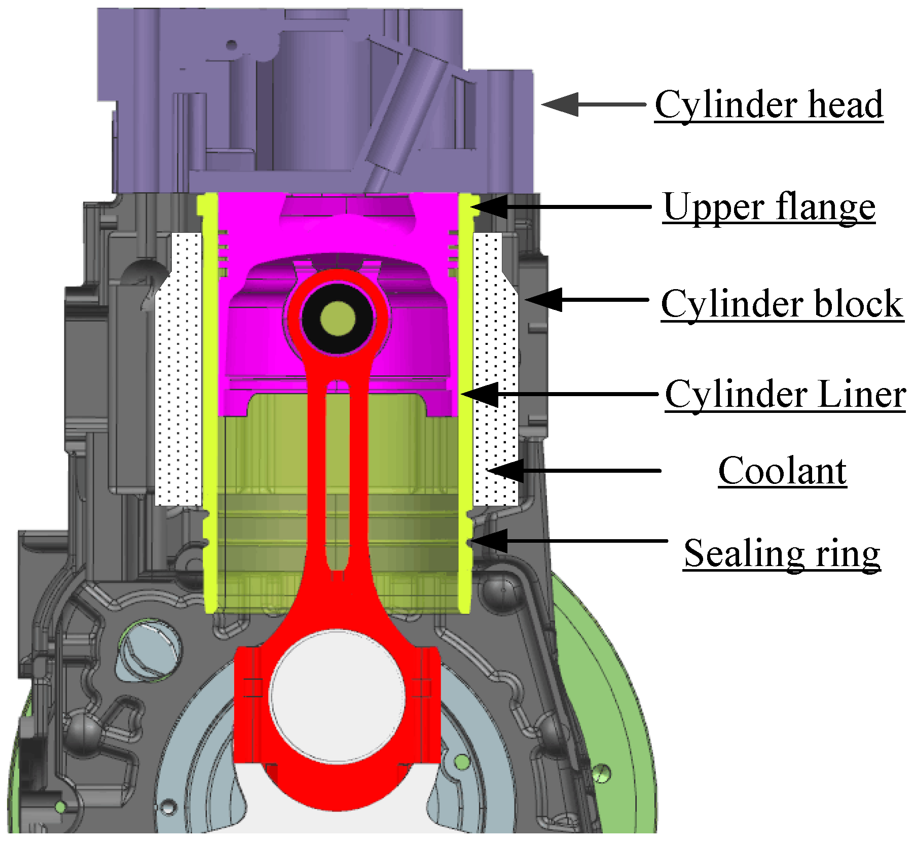
The cylinder liner is a central component of a reciprocating engine. As well as being part of the combustion chamber, the liners provide swept space for piston reciprocation. Figure 2 illustrates the construction of a typical wet cylinder liner. The upper flange of the liner is bolted to the cylinder head and cylinder block, restricting its axial degree of freedom. The liner’s lower external surface is mounted onto the engine body within the clearance fitting. To prevent the liquid coolant leaking into the crankcase, the wet liner’s lower end is sealed by a rubber sealing ring.
The modelling and simulation steps of piston and cylinder assembly are represented in Figure 3. After importing the three-dimensional model of components into the finite element software ANSYS Workbench (v16, Ansys Inc., Canonsburg, PA, USA), the material definition of the different structural parts is first required. In this study, ductile cast iron QT600-3 (Taiyuan Iron & Steel Co., Ltd., Taiyuan, Shanxi, China) is used for the liner [17], while aluminium alloy ZL108 (Taiyuan Iron & Steel Co., Ltd., Taiyuan, Shanxi, China) serves for the piston. Computational efficiency is improved by ignoring certain geometric details on the outer surface of cylinder liner. The cylinder liner was modelled as having 7121 hexahedral isoparametric solid elements, and computing resources and solution time were reduced by modelling other components as a rigid body.
Before performing the simulation calculation, the boundary condition and excitations are required to be set successively. Figure 2 illustrates the cylinder liner’s boundary condition; the liner is a non-uniform cylinder-shaped shell with end-flanges. Incorrect definition of the boundary condition can cause alteration of liner modal characteristics. To avoid this, fixed joints and clearance fits have been modelled through the construction of corresponding frictionless contact pairs, avoiding errors caused by over-simplification and inappropriate structural equivalents in modelling cylinder dynamics [8]. To handle the nonlinearities of the contact constraints and improve the computing efficiency, a reduced integration method—the Newmark implicit integration method—was selected to solve the motion equations of the dynamic process. Even so, it takes up to seven hours to solve a complete operating cycle.
Combustion shock and piston slap are generally considered to be the two main excitation sources of the cylinder dynamics [18]. According to the authors’ previous paper, the response induced by combustion shock has a predicted amplitude of approximately 0.02 microns, being much less than the friction surfaces’ roughness, which can be considered negligible for predicting lubrications between piston rings and liners. Therefore, this paper will only simulate the dynamic deformation of liner surface caused by piston slaps, and study its influence on the lubrication behaviour.
Driven by the in-cylinder pressure, the piston assembly moves laterally and knocks the liner surface ceaselessly. The piston assembly’s axial movement is controlled by the crankshaft and connecting rod mechanism. Equation (2) shows the calculation of side-thrust force, which drives the piston’s lateral movement. Figure 4a demonstrates that translational degree of freedom of the piston is perpendicular to the moving plane, and it is set as free to avoid over-constraint. The calculation is simplified by setting rotational degree of freedom (DOF) of the piston tilting motion as free, while ignoring all other rotational freedoms. Mathematically, this side-thrust force Fy can be expressed as Equation (2) [19]:
F y = ( P c P i ) λ sin ω t / 1 + ( λ sin ω t ) 2 = [ P c m l r c ω 2 ( cos ω t + λ cos 2 ω t ) ] × λ sin ω t / 1 + ( λ sin ω t ) 2
where λ = rc/l, rc is the crank radius and l is the length of the connecting rod. The ml is the equivalent mass of the piston assembly. Pc is the longitudinally acting combustion force and Pi is the inertial force of the moving piston assembly.
Figure 4b shows the liner deformation response to piston slap at a 370° crank angle under the operating condition: 1800 rpm and 40 Nm. It shows that the piston slap-induced deformation occurs on the entire liner structure and exhibits a distinct asymmetrical feature which is consistent with the piston’s impact characteristics. The amplitude of liner deformation response to piston slap is predicted to be about 0.15 microns, close to 20% of the roughness amplitude, which may affect the oil film distribution.
To better understand dynamic responses of the liner to piston slaps, it is necessary to examine the radial displacement response of a node on the anti-thrust side of the studied liner. Figure 5 shows the short-time Fourier transform (STFT) result of the predicted liner responses to piston side-thrust force in a single-cylinder diesel engine burning standard diesel at an operating condition of 1800 rpm speed and 40 Nm torque. Figure 5b illustrates the piston’s side-thrust force, the predicted displacement, and the predicted acceleration, to facilitate the analysis of the STFT result. The STFT analysis is used to highlight the time–frequency characteristics of the clean prediction, rather than wavelet analysis such as continuous wavelet transform, which needs considerable analyses to determine its optimal parameters.
In Figure 5a, it is easy to identify six separate and transient responses corresponding to highs and troughs of piston side-thrust force, marked as Impact A to Impact F. For the most part, these responses are in the frequency band 929.0–3128.7 Hz relating to the first four modes of cylinder structure identified by modal experiments [7,8].
Previous studies [18,19] have often chosen the frequency range between 500 and 3000 Hz as the analysis band for the identification and analysis of vibration events induced by piston slap. As Figure 5 shows, there is probably some truth to this, which may stem from mode characteristics inherent in liner structures. This study demonstrates that the majority of dynamic responses induced by piston slap come in the range 900–3000 Hz, near the frequency band of the first four liner modes, and this suggests that the dynamic response of cylinder liners may depend on their structural modes to a high degree.
After obtaining the liner deformation by dynamic simulation, the influence of the cylinder deformation on the lubrication behaviours between the piston ring and liners can be studied by extracting the deformation and then introducing it into the lubrication model.

2.2. Geometric Extraction and Coordinate Transformation

In order to couple the geometric deformation of the liner surface accurately into the lubrication model, a series of transformation operations are required, which includes geometric extraction, coordinate transformation, and static distortion removal.
Figure 6 shows the flowchart of the geometric extraction and coordinate transformation process, from the finite element simulation results in ANSYS to the dynamic deformation of liner surface that can be used in the mathematical lubrication model. After extracting geometric deformation from ANSYS and importing it into a MATLAB package, a three-dimensional cylindrical shell can be drawn based on the spatial positions of the nodes, as shown in Figure 6b. The colour of the nodes represents the amplitude of displacement increment relative to the global coordinate system.
To facilitate the modelling and calculation, in the modelling of two-dimensional film thickness, the cylindrical surface of a liner is often equivalently converted into a square plane. Therefore, before the introduction of deformations into a lubrication model, the selected nodes should be transformed from the spatial coordinate system (x, y, z) into a two-dimensional coordinate system containing the axial and circumferential directions, as shown in Figure 6c.
As seen in Figure 6c, the magnitude of liner deformation reached almost 0.1 millimetre, which is inconsistent with the existing simulation results [20], which indicates that the amplitude of the liner deformation should be at the micron level. Under the excitation of piston impact force, the liner exhibited significant overall translation, mainly perpendicular to the cylinder axis. It is essential to filter and suppress this unwanted overall translation before the processing of coordinate transformation, to avoid introduction of significant errors into the local deformations. Specifically, a cylinder shell should be fitted according to the geometric profile of the node set in Figure 6b, firstly. Then, by subtracting the coordinate values of the fitted cylindrical shell, accompanied by coordinate transformations, a two-dimensional deformation surface of the liner excluding the overall translation can be obtained, as shown in Figure 6d.
It should be noted that, compared with the axial length of the liner (19.8 mm), the axial height of the piston ring is very small, with only 3 mm, in the studied cylinder assembly. Furthermore, the axial position of the ring is continuously changing along with the crank rotating. Based on the instantaneous axial position of the piston, the deformation region in contact with the piston ring surface can be accurately intercepted.

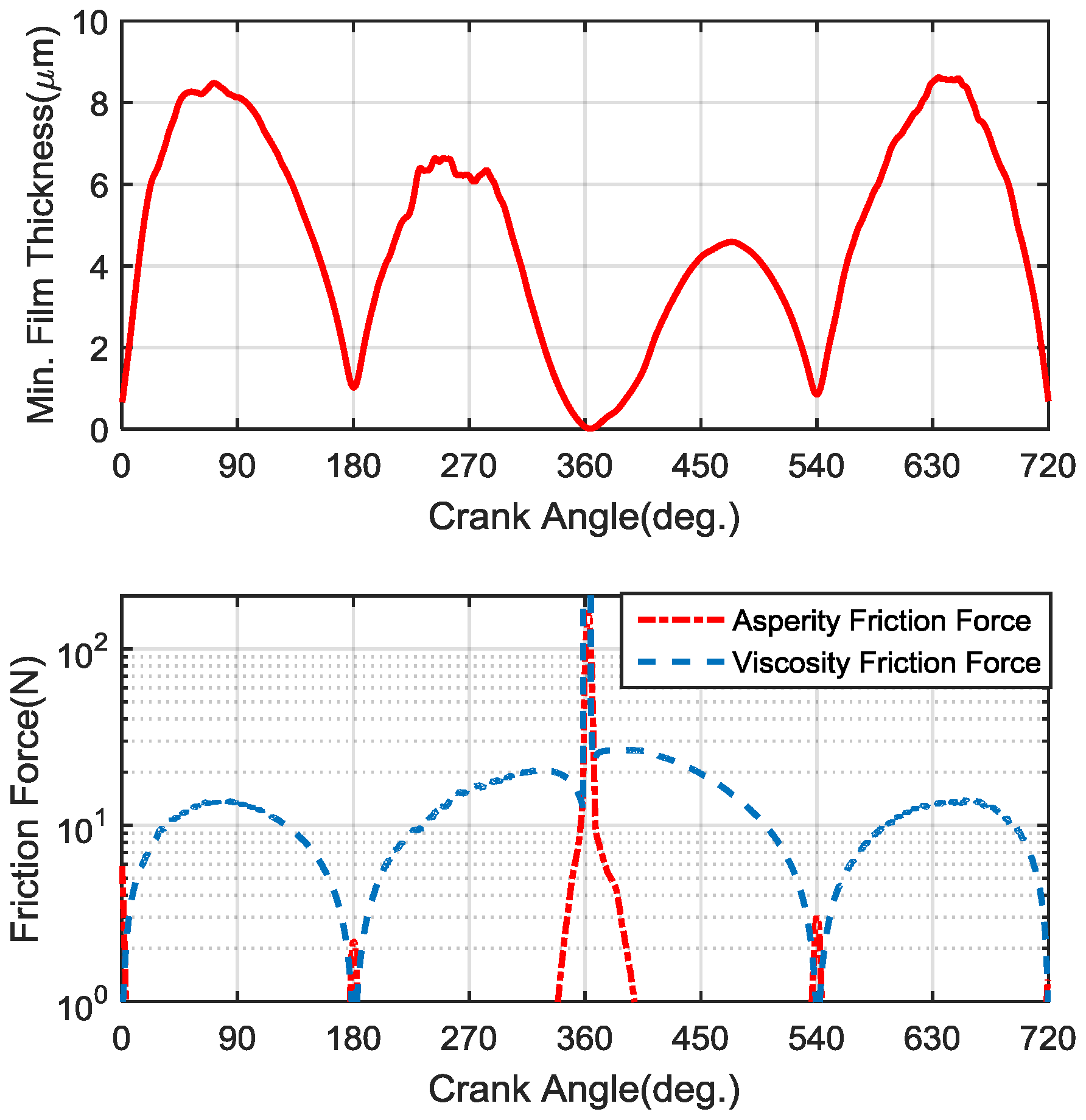
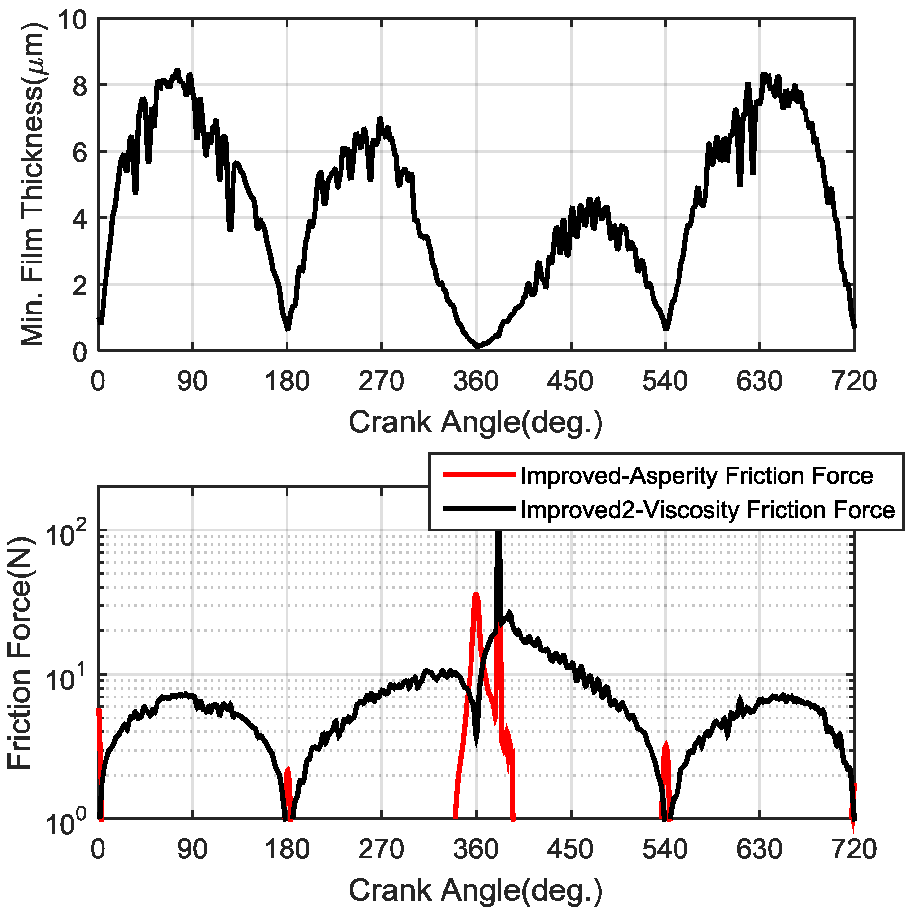
3. Development of Dynamic Deformation Based Lubrication Models

In principle, there are two ways in which the dynamic deformation affects the lubrication behaviours between the piston rings and liners: one is that the deformation of the surface morphology directly changes the distribution of lubricating oil film, thus changing the asperity friction; the other is that the deformation may cause changes in shear properties, i.e., shear stress factors, of lubricating oil, resulting in viscous friction changes.

3.1. Governing Equations

3.1.1. Average Reynolds Equation

In a mixed lubrication regime, Patir and Cheng [14,21] and Greenwood and Tripp [22] improved the average Reynolds equation to describe the isothermal, incompressible lubricant behaviour between the ring and liner rough surfaces as Equation (3):
x ( x h 3 η p ¯ x ) + y ( y h 3 η p ¯ y ) = 6 U ( h ¯ T ) x + 6 U σ ( s ) x + 12 ( h ¯ T ) t
where ϕ x , ϕ y are pressure flow factors, ϕ s is the shear flow factor, p ¯ is the mean pressure, and σ is the composite root mean square (RMS) roughness of ring and liner, U is the piston primary velocity, η is the lubricant viscosity.
Simultaneous solution of Equation (3) requires the determination of the bulk rheological state of the lubricant in the contact. In the isothermal analysis presented here, the lubricant dynamic viscosity can be described as functions of the pressure and temperature as Equation (4):
η = η 0 { ( ln η 0 + 9.67 ) [ ( 1 + 5.1 × 10 9 p ) Z × ( T 138 T 0 138 ) S 1 ] }
wherein η 0 is the lubricant viscosity at atmospheric pressure and ambient temperature 40 °C, p is the pressure, and Z and S are the dimensionless viscosity–pressure coefficient and viscosity–temperature coefficient, respectively, which can be calculated according to the literature [3,23]. T0 is the ambient lubricant temperature, and the lubricant temperature T is calculated based on a series of heat flow balance equations [1,3,24].

3.1.2. Asperity Contact

When, and only when, hydrodynamic pressure is not enough to keep matching surfaces apart, asperities of two surfaces can be contact. Greenwood-Tripp’s rough surface contact model estimated the asperity contact load based on the surface mean separation and other statistical parameters [10,11]. The average contact pressure Pa was related to the density of asperities μ, the curvature of asperity of radius β, composite surface roughness σ, and composite material modulus E. It was defined as Equation (5):
P a ( h ) = 16 2 15 π ( σ β μ ) 2 E σ β F 2.5 ( h σ )
where
F 2.5 ( x ) = 1 2 π x ( s x ) 2.5 e s 2 / 2 d s
1 E = 1 v 1 2 E 1 + 1 v 2 2 E 2 .
In Equation (7), E1 and E2 are Young’s modulus of ring and liner, and ν1 and ν2 are their corresponding Poisson’s ratio.

3.1.3. Calculation of the Frictional Force

The shearing of asperities and viscous lubricant film generates the friction force in the mixed lubrication regime. Viscous friction is attributed to generated shear stress arising from entraining motion of the lubricant as well as pressure gradient in a converging–diverging wedge. The hydrodynamic component of average friction force Fh can be predicted by an integration of viscous shear stress across the sliding surfaces as Equation (8):
F h = A τ d A
Furthermore, to meet different sliding scenarios, the local shear stress τ can also be expressed in terms of the mean quantities and three empirical shear stress factors ϕ f , ϕ f p , and ϕ f s .
The asperity component of friction force Fa is caused by contact between the ring surface and cylinder wall,
F a = μ f B / 2 B / 2 P a d x
where μ f is the friction coefficient under lubricated contact (boundary lubrication). B is the ring axial thickness.
The total friction force between the piston ring and the cylinder liner is
F f = F h + F a .
The key parameters used in this study are given in Table 1, in which the surface accuracy parameters are obtained from the engine manufacturer.

3.2. The Introduction of Dynamic Deformations into the Oil Film Formation and Distribution Model

For the conventional lubrication models, the initial film thickness and film profile are predefined. During the computation, the contour of film distribution is changeless; only the thickness of the overall film surface is modified to adjust the bearing capacity of the film or asperities for achieving overall force balance. Therefore, placing the dynamic deformations of the liner surface, in the form of a predefined condition, into the calculation will not change the core algorithm of Reynolds equations, and not produce any adverse effect on the accuracy of the calculation.
Figure 7 depicts a conjunction between the piston ring and cylinder liner with surface roughness. Here, the function hT(x) describes the local film thickness, including surface roughness.
For one-dimensional lubrication, the local film thickness hT is given by
h T = h + Δ 1 + Δ 2
where h is the nominal film thickness, ∆1 is the ring surface roughness amplitude, and ∆2 is the liner surface roughness amplitude. The nominal film thickness h = hmin(t) + hx(x), giving
h T ( t ) = h min ( t ) + h x ( x ) + Δ 1 + Δ 2 .
Taking the deformation amplitude of the liner surface ∆x into account in the film formation model, the nominal film thickness can be improved as
h T _ d e f o r m s = h min ( t ) + h x ( x ) + Δ 1 + Δ 2 + Δ x = h T ( t ) + Δ x
By analogy, for the two-dimensional lubrication, the film thickness is given by
h T _ d e f o r m s ( t ) = h min ( t ) + h x ( x ) + h y ( y ) + Δ 1 + Δ 2 + Δ x + Δ y = h T ( t ) + Δ x ( t ) + Δ y ( t ) = h T ( t ) + Δ d e f o r m s ( t )
where the two-dimensional deformation of the liner surface matched with the piston ring is combined with axial deformation ∆x and circumferential deformation ∆y.

3.3. The Numerical Solution of Shear Stress Factors

As mentioned in Equation (8), Patir and Cheng [14] introduced three stress factors to consider the effect of surface roughness on shear stress acting on a rough surface in a highly viscous flow. The average shear stress τ is given by
τ = μ U h ( ϕ f ϕ f s ) + ϕ f p h 2 ( p x )
where ϕ f is a geometric stress factor, and ϕ f s and ϕ f p are the shear stress and press stress factors, respectively.
It should be noted that all stress factors proposed by Patir and Cheng are only applicable to artificial Gaussian random rough surfaces, and these factors are constants over the entire surface. However, the cylinder liner surface are highly non-Gaussian when considering the dynamic deformation close to the order of surface roughness, and the shear stress τ is not equal everywhere. Therefore, the local stress factors should be calculated locally and real-timely.
It is necessary to mesh the solve region of ring surface with m × n nodes, and to use the finite difference method to solve the local stress factors in the discrete domain. The m and n are the respective number of nodes in the axial and circumferential directions. Figure 8 shows surface interpolation between nodes for stress factor calculation.
The geometric stress factor ϕ f functions only of rough surface geometry, and is defined by [15]:
ϕ f = h · 1 m ( n 1 ) i = 1 n 1 j = 1 m ln ( h i / h i + 1 ) h i h i + 1 .
The ϕ f p is a correction factor for the mean pressure flow component of the shear stress, is defined by [15]:
ϕ f p = 1 m ( n 1 ) i = 1 n 1 j = 1 m 2 h i h i + 1 ( P i + 1 , j P i , j ) ( h i + h i + 1 ) Δ x h 2 · d P d x .
The ϕ f s is another correction term which arises from the combined effect of roughness and sliding, is defined by
ϕ f s = 1 m ( n 1 ) i = 1 n 1 j = 1 m h i h i + 1 ( P i + 1 , j P i , j ) ( h i + h i + 1 ) Δ x μ U h .
Substituting the improved shear stress factors into Equations (15) and (8), then the viscosity friction force considering the liner dynamic deformation can be calculated in real time.
Based on these equations above, a computational fluid dynamics (CFD) code in the MATLAB platform was developed to predict oil film distribution and various friction forces numerically.

4. Results and Discussion

4.1. Friction Responses to Dynamic Deformations of Liner Surface

After running throughout an entire working cycle, the minimum oil film thickness Hmin and friction forces versus the crank angle with and without considering dynamic deformations can be calculated and are presented in Figure 9, Figure 10 and Figure 11. In order to study the differences in influences of surface dynamic deformations on the oil film distribution and oil shear properties, two improved lubrication models are proposed, which only considers the effect of dynamic deformation on the oil film distribution named improved model 1, and the model considering both the influences on oil film distribution and oil shear properties is named as improved model 2. Figure 10 shows the minimum oil film thickness and friction force curves predicted from improved model 1, which only considers the influence on the oil film distribution. For comparison, Figure 11 presents the curves simulated based on improved model 2, which considers both influences.
As shown in Figure 10 and Figure 11, the minimum oil film thickness Hmin considering the impact of liner dynamic deformation shows significant oscillations throughout the entire operating cycle, especially in the mid-strokes with higher sliding speed. The friction curves of the improved models also manifest some obvious oscillations. This indicates that the lubrication behaviour between the piston rings and liners can indeed be affected by the dynamic deformations of cylinder liners.
For comparing and analysing the influence of liner deformations on lubrication behaviours, especially the effect of the improvement in shear stress factors, the predicted minimum oil film thicknesses, and friction forces based on three models, are drawn together in Figure 12. It can be seen from Figure 12 that the minimum film thicknesses predicted by the two improved models are close and slightly lower than that of the original model. The smaller film thickness is due to the emergence of surface deformation. In the case where the average film thickness of the original and improved models are close to each other, the local troughs present in the surface deformation may result in a decrease in the minimum film thickness of improved models relative to the original model. While the difference between the minimum film thicknesses predicted from the models before and after the improvement of shear stress factor, i.e., between the improved 1 and improved 2 models, is not obvious, which may be because the shear stress factors do not significantly affect the radial force balance of the piston ring.
The friction force amplitude of improved model 1 is close to that of the original model, indicating that the introduction of surface deformation does not cause significant difference in frictional force. While the friction force of improved model 2 shows a significant decrease relative to the original model. It indicates that the surface deformation can significantly affect the stress factors, causing a decrease in viscous frictional force. Figure 12 shows that the improved total friction forces oscillate significantly in the power stroke, and the asperity friction forces also exhibit a significant oscillation near the top dead centre. For further comparative analysis, an enlarged view of friction forces predicted by three different models are plotted, as shown in Figure 13.
In the middle of the power stroke, the viscous friction force obtained from improved model 2 shows an obviously decline compared to the original model. This kind of friction reduction may be attributed to the changes of shear stress factor ϕ f s , as a result of the introduction of surface dynamic deformations. The ϕ f s is the correction factor for the combined effect of sliding roughness on the shear force [14]. With the introduction of surface deformation, the shear stress factor ϕ f s will increase significantly [15,25]. With the increase of ϕ f s , the difference between the sliding velocity correction factor ϕ f and shear stress factor ϕ f s subsequently exhibited obvious decrease, as seen in Equation (15). Therefore, the local shear stress τ can be reduced accordingly, with the increasing of shear stress factor ϕ f s . The lubricant viscosity may change slightly under the changes in pressure distribution of oil film, as the result of changes in oil distribution. However, the simulation results of improved model 1 show that the friction force did not decrease apparently before the stress factor equations were improved. This suggests that the inclusion of surface deformations can cause changes in the flow shear factors and lead to the observable reduction in viscous friction forces.
According to improved model 1, the inclusion of dynamic deformation will cause friction oscillations, showing that the reason for the friction oscillations may be caused by the dynamic changes in the oil film distribution. On the other hand, according to improved model 2, the frictional force decreased obviously after the modification of shear stress factors, indicating that the friction reduction may be caused by the change of the oil shear properties. The root cause of these differences between these models before and after the improvements is the influence of dynamic deformation, and lubricant viscosity is the medium of this effect.
As seen in Figure 13, around the combustion top dead centre (TDC) at a crank angle of 360°, the value of asperity friction considering liner deformation is lower than that of original model. Due to the introduction of dynamic deformation, the lubricating condition between the matched surfaces is improved, with the help of emergence of many local surface pits and its resulting reduction of the effective contact area of the asperity contact. This might indicate that the dynamic deformation of the liner can help to reduce the asperity friction near the combustion TDC, normally regarded as the most serious position of wear, and to enhance the operation efficiency and service life of engines.
It should be noted that between the crank angles of 376° and 385°, both the asperity friction and viscosity friction curves predicted by the two improved models show a significant increase and form a sharp peak. This may be due to the fact that under the condition of low sliding speed and thin oil film, the severe surface deformation caused by the piston slap can result in an increase in the effective contact area of the asperity contact, while deteriorating the viscous lubrication state.
Under different speed and load conditions, the asperity friction force shows some sharp peaks at a relatively fixed angle range from 375° to 385°, as seen in Figure 13a–d. The amplitude of the sharp peak under high load conditions is significantly higher than that under the low load condition. This may be caused by more intense combustion behaviours, which are induced by more fuel injection.

4.2. Time-Frequency Analysis

The experimental study conducted by Michael Gore et al. [13] strongly confirmed the existence of oscillations in the piston axial friction force through a direct measurement, as seen in Figure 14. Regarding the cause of oscillations in the friction force, Michael Gore et al. [13] suggested that these oscillations might be related to the order harmonics of the engine, without offering more vigorous evidence. To fill this gap, it is essential to analyse the correspondence between the friction oscillation and surface deformation of the liner structure. As shown in Figure 15, a short-time Fourier transform (STFT) result of the friction force predicted by improved model 2 under the operating condition of 1800 rpm and 40 Nm torque is presented.
As can be seen in Figure 15a, in the power stroke, sustained oscillations can be clearly observed in the frequency range of 1000–1600 Hz at the mid-stroke, as marked with a blue rectangle. Its frequency band is close to the 1229 Hz of the second mode of cylinder liner identified by the modal experiment. This suggests that the dynamic deformations of the cylinder liner produced a profound influence on the friction behaviours between rings and liners.
In addition, the other local features of friction force can also be associated with the dynamic responses of the cylinder liner. As seen in Figure 15a, the significant dynamic response around the crank angle of 100° and located in the frequency range from 1500 to 3500 Hz, marked with a grey rectangle, can well correspond to the local dynamic event Impact F caused by piston slap. Likewise, the local response at the crank angle of 630° in the frequency band of the second mode response can also perfectly correspond to the dynamic event Impact D in the STFT result of the liner vibration in Figure 5.
All of these results indicate that the dynamic deformation of the cylinder liner is one of the most important factors causing and affecting the oscillations in friction. In other words, the oscillating characteristics of friction and lubrication behaviours between the piston and liners are greatly determined by the dynamic characteristics of the cylinder structure.

4.3. Experimental Verification

As mentioned above, between 380° and 385°, both the asperity friction and viscosity friction curves predicted by improved models show a drastic oscillation, indicating the emergence of a serious instantaneous friction and wear. Based on the numerical prediction, it can be deduced that a severe wear is likely to occur on a narrow band of liner surface which corresponds to the crank angle of 380–385°. To confirm this finding, a cylinder liner used for approximately 500 h was detached from a single-cylinder diesel engine and photographed from the inside of the cylinder, as seen in Figure 16. By splicing and reorganising multiple photographs, a panoramagram of the inner surface of this used liner can be obtained, as shown in Figure 17.
As seen in the panoramagram, there exist four wear marks that can be clearly observed on the inner surface of the used liner. The first three wear marks can well correspond to the top compression ring, the second compression ring, and the oil scraper ring respectively, as illustrated in Figure 16. When the piston reaches the top dead centre, due to the low sliding speed and harsh pressure boundary conditions, the lubricant film between the ring and the liner is extremely thin and insufficient to separate the matched surfaces, resulting in the severe wear, i.e., these observable marks.
In addition, there is another wear mark below the scraper ring’s mark, with a distance of 4 mm, marked as d in Figure 17. Further calculations suggest that the position of the fourth mark corresponds well to the position of the top ring at crank angle of 380°. This indicates that the predicted serious instantaneous friction does appear in this position, around crank angle 380°, as predicted in the improved lubrication model.
Furthermore, the presence of sharp asperity friction can also be confirmed by means of a bench test. In the vicinity of 380°, driven by the combustion force and inertial force, the piston will knock the cylinder liner and cause severe structural vibration. The low frequency vibration response caused by the piston knock is likely to cover and suppress the response of the short-time asperity friction. Studies have shown that acoustic emission (AE) technology can effectively detect the dynamic response associated with friction events [26,27]. Acoustic emissions are the high frequency transient elastic waves that are spontaneously generated from a rapid release of strain energy caused by the deformation or fracture of materials. For piston rings and cylinder liner assemblies, these stress waves are induced by the asperity and viscosity friction effects. Both such effects are more proportional to relative velocity between the contacting materials [27]. Therefore, it is more convincing to use the AE signal after high-pass filtering to detect the friction event rather than the conventional vibration analysis.
Gu and Wei et al. [26,27] have carried out a series of theoretical and experimental studies on the friction and wear behaviours between the piston and liners using acoustic emission technology. Their study shows that the AE signal processed by high-pass filtering and wavelets multi-resolution analysis can effectively characterize the frictional state between the piston ring and cylinder liner. Therefore, it is a feasible and reliable means to verify the short-term serious instantaneous friction phenomenon around 380° by acoustic emission signal analysis.
In order to measure the acoustic emission signal associated with the friction behaviour between the piston rings and cylinder liners, a SR800 AE sensor from Soundwel Technology Co., Ltd. (Beijing, China) is installed directly on the anti-thrust side of liner outer surface in a single-cylinder diesel engine through a waterproof adapter, as seen in Figure 18a. The sensor position is close to the middle of the piston stroke. The geometrical parameters and in-cylinder pressure data used in the modelling of Section 2 and Section 3 are derived from the single-cylinder diesel engine of the test bench, detailed in Table 2. Therefore, it is highly reliable to study the friction behaviours based on the AE signal acquired from the test engine. In addition, engine speed and time-based crank angle are also recorded for results calibrations. The experimental setup is illustrated in Figure 18b. All of the data was recorded simultaneously by a multiple channel acquisition system.
For purposes of comparison, raw signals were collected from the sensors under different operating conditions, with the engine was running at the two speeds of 1000 rpm and 1800 rpm, under two loads of 10 Nm and 40 N m at each speed.
After high-pass filtering and threshold denoising, signal components related to the frictional event can be obtained from the acoustic emission signal, as seen in Figure 19.
As can be seen from Figure 19, in addition to the AE peak associated with the asperity friction at the TDC, there is another minor peak in the range of 375–385°, highlighted with two vertical red dotted lines. For all four operating conditions, the AE signal exhibits a significant peak in the vicinity of 380 degrees. This indicates that there is indeed a short-time asperity frictional event at about 20° after the combustion TDC, which is consistent with the numerical prediction.
The amplitude of the sharp peak under high load condition, i.e., 1800 rpm and 40 Nm, is significantly higher than that under the low load condition, as seen in Figure 19. This may be caused by more intense combustion behaviours which induced by more fuel injection. This trend is consistent with the simulation result in Section 4.1, which further confirmed the reliability of the findings.

5. Conclusions

In the paper, an improved lubrication model of the top compression ring and cylinder liner considering the influence of liner dynamic deformation on lubrication behaviours has been presented. Comparative analysis of simulation results based on original and improved models indicate that the actual friction and wear behaviours between piston rings and liners are far more complex than that which had been previously predicted. The main conclusions can be made as follows:
(1)
The minimum oil film thicknesses and friction forces predicted by the improved lubricant model considering the impact of liner dynamic deformation show significant oscillations related with liner modal frequencies, indicating that the lubrication behaviours between the piston rings and liners can indeed be affected by the dynamic deformations of cylinder structures.
(2)
Around the combustion TDC, the value of asperity friction predicted by the improved model considering liner deformation is lower than that of the original model, indicating that the dynamic deformation of the liner can help to reduce the asperity friction between the matched surfaces and enhance the operation efficiency and service life of engines.
(3)
In the middle of piston strokes, the viscous friction force obtained from the improved model shows an obvious decrease compared to the original model, which suggests that the inclusion of surface deformations can cause changes in the flow shear factors and lead to the observable reduction in viscous friction forces.
(4)
Under the condition of low sliding speed and thin oil film, the severe surface deformation caused by the piston slap can always result in a serious instantaneous asperity friction after combustion TDC at the crank angle of 380°–385°. This phenomenon has been confirmed by both wear image analysis and acoustic emission signal analysis. The rationality of the improved model constructed in this paper has also been verified to a great degree of extent.
The correlation between the friction oscillation and structural modes, as well as the possible influence of high frequency vibration on the physicochemical properties of the oil and its lubricating properties, need to be verified and studied with more bench-based tests. Deepening the understanding of dynamic deformations on the lubrication behaviour will help optimize the design of friction pairs and the selection of lubricants. By improving the structure design of the cylinder assemblies and even adding additional vibration, it is possible to change the structural vibration characteristics to achieve the optimization of lubrication performance, thus realizing the friction reduction and operating efficiency improvement.

Acknowledgments

The support of the Natural and Scientific Foundation of China (No. 51375326) is gratefully acknowledged.

Author Contributions

All authors contributed to the research work. Guoxing Li, Xingchen Lu and Fengshou Gu established the finite element method-based model and designed the experiments. Tie Wang and Andrew Ball analysed the simulation results and reviewed the research work. Li Zhang and Chunfeng Zhang participated in the experiments.

Conflicts of Interest

The authors declare no conflict of interest.

References

  1. Rahmani, R.; Rahnejat, H.; Fitzsimons, B.; Dowson, D. The effect of cylinder liner operating temperature on frictional loss and engine emissions in piston ring conjunction. Appl. Energy 2017, 191, 568–581. [Google Scholar] [CrossRef]
  2. Choi, J.; Lee, S.; Park, S. Friction losses modeling of piston rings for various combustion pressures in diesel engine. J. Mech. Sci. Technol. 2016, 30, 5739–5747. [Google Scholar] [CrossRef]
  3. Zavos, A.; Nikolakopoulos, P. Thermo-mixed lubrication analysis of coated compression rings with worn cylinder profiles. Ind. Lubr. Tribol. 2017, 69, 15–29. [Google Scholar] [CrossRef]
  4. Andersson, P.; Tamminen, J.; Sandström, C.-E. Piston Ring Tribology. A Literature Survey; VTT Tiedotteita-Research Notes 2178; VTT Industrial Systems: Metallimiehenkuja, Finland, 2002. [Google Scholar]
  5. Chittenden, R.J.; Priest, M. Analysis of the Piston Assembly, Bore Distortion and Future Developments. In Tribology Series; Taylor, C.M., Ed.; Elsevier: Amsterdam, The Netherlands, 1993; Volume 26, pp. 241–270. [Google Scholar]
  6. Reipert, P.; Voigt, M. Simulation of the Piston/Cylinder Behavior for Diesel Engines. In Proceedings of the SAE 2001 World Congress, Detroit, MI, USA, 5–8 March 2001. [Google Scholar]
  7. Li, G.; Gu, F.; Wei, N.; Xu, Y.; Ball, A.D.; Wang, T. A validated finite element model for predicting dynamic responses of cylinder liners in an IC engine. In Proceedings of the 2016 22nd International Conference on Automation and Computing (ICAC), Colchester, UK, 7–8 September 2016; pp. 126–131. [Google Scholar]
  8. Li, G.; Gu, F.; Wang, T.; Yang, T.; Ball, A. Investigation into the dynamic response of cylinder liners in an IC engine based on a validated finite-element model. Syst. Sci. Control Eng. 2017, 5, 56–69. [Google Scholar] [CrossRef]
  9. Li, G.; Gu, F.; Wang, T.; You, J.; Ball, A. Investigation into the Vibrational Responses of Cylinder Liners in an IC Engine Fueled with Biodiesel. Appl. Sci. 2017, 7, 717. [Google Scholar] [CrossRef]
  10. Ma, M.-T.; Smith, E.H.; Sherrington, I. Analysis of lubrication and friction for a complete piston-ring pack with an improved oil availability model: Part 2: Circumferentially variable film. Proc. Inst. Mech. Eng. Part J J. Eng. Tribol. 1997, 211, 17–27. [Google Scholar] [CrossRef]
  11. Usman, A.; Cheema, T.A.; Park, C.W. Tribological performance evaluation and sensitivity analysis of piston ring lubricating film with deformed cylinder liner. Proc. Inst. Mech. Eng. Part J J. Eng. Tribol. 2015, 229, 1455–1468. [Google Scholar] [CrossRef]
  12. Meng, F.M.; Wang, X.F.; Li, T.T.; Chen, Y.P. Influence of cylinder liner vibration on lateral motion and tribological behaviors for piston in internal combustion engine. Proc. Inst. Mech. Eng. Part J J. Eng. Tribol. 2015, 229, 151–167. [Google Scholar] [CrossRef]
  13. Gore, M.; Theaker, M.; Howell-Smith, S.; Rahnejat, H.; King, P.D. Direct measurement of piston friction of internal-combustion engines using the floating-liner principle. Proc. Inst. Mech. Eng. Part D J. Automob. Eng. 2014, 228, 344–354. [Google Scholar] [CrossRef] [Green Version]
  14. Patir, N.; Cheng, H.S. Application of Average Flow Model to Lubrication between Rough Sliding Surfaces. J. Tribol. 1979, 101, 220–229. [Google Scholar] [CrossRef]
  15. Jocsak, J.J.A. The Effect of Surface Finish on Piston Ring-Pack Performance in Advanced Reciprocating Engine Systems. Ph.D. Thesis, Massachusetts Institute of Technology, Cambridge, MA, USA, 2005. [Google Scholar]
  16. Cheng, J.; Meng, X.; Xie, Y.; Zhou, B. Effects of Cylinder Liner Deformation and Piston Ring Conformability on the Blowby and Tribological Performance of Piston Ring Pack. Lubr. Eng. 2016, 41, 1–9, 42. [Google Scholar]
  17. ISO 1083:2004—Spheroidal Graphite Cast Irons—Classification. ISO. Available online: http://www.iso.org/iso/catalogue_detail.htm?csnumber=33243 (accessed on 31 July 2016).
  18. Dolatabadi, N.; Theodossiades, S.; Rothberg, S.J. On the identification of piston slap events in internal combustion engines using tribodynamic analysis. Mech. Syst. Signal Process. 2015, 58–59, 308–324. [Google Scholar] [CrossRef] [Green Version]
  19. Geng, Z.; Chen, J. Investigation into piston-slap-induced vibration for engine condition simulation and monitoring. J. Sound Vib. 2005, 282, 735–751. [Google Scholar] [CrossRef]
  20. Cho, J.R.; Moon, S.J. A numerical analysis of the interaction between the piston oil film and the component deformation in a reciprocating compressor. Tribol. Int. 2005, 38, 459–468. [Google Scholar] [CrossRef]
  21. Patir, N.; Cheng, H.S. An Average Flow Model for Determining Effects of Three-Dimensional Roughness on Partial Hydrodynamic Lubrication. J. Tribol. 1978, 100, 12–17. [Google Scholar] [CrossRef]
  22. Greenwood, J.A.; Tripp, J.H. The Contact of Two Nominally Flat Rough Surfaces. Proc. Inst. Mech. Eng. 1970, 185, 625–633. [Google Scholar] [CrossRef]
  23. Roelands, C.J.A. Correlation Aspects of the Viscosity–Temperature-Pressure Relationship of Lubricating Oils; Technische Hogeschool te Delft: Delft, The Netherlands, 1966. [Google Scholar]
  24. Olver, A.V.; Spikes, H.A. Prediction of traction in elastohydrodynamic lubrication. Proc. Inst. Mech. Eng. Part J J. Eng. Tribol. 1998, 212, 321–332. [Google Scholar] [CrossRef]
  25. Li, G. Investigation into the Dynamic Responses and Tribological Characteristics of Cylinder Liners in a IC Engine with Alternative Fuels. Ph.D. Thesis, University of Huddersfield, Huddersfield, UK, 2016. [Google Scholar]
  26. Fan, Y.; Gu, F.; Ball, A. Modelling acoustic emissions generated by sliding friction. Wear 2010, 268, 811–815. [Google Scholar] [CrossRef]
  27. Wei, N.; Gu, F.; Wang, T.; Li, G.; Xu, Y.; Yang, L.; Ball, A.D. Characterisation of acoustic emissions for the frictional effect in engines using wavelets based multi-resolution analysis. In Proceedings of the 2015 21st International Conference on Automation and Computing (ICAC), Glasgow, UK, 11–12 September 2015; pp. 1–6. [Google Scholar]
Figure 1. Cylindrical coordinate system and Fourier orders.
Energies 10 02122 g001
Figure 2. Construction of wet cylinder liner.
Energies 10 02122 g002
Figure 3. Flow chart of simulations.
Energies 10 02122 g003
Figure 4. (a) Excitation configurations; (b) Total deformation of cylinder liner (Unit: mm).
Energies 10 02122 g004
Figure 5. Short-time Fourier transform (STFT) of responses to piston slaps under 40 Nm and 1800 rpm: (a) STFT of predicted liner responses; (b) piston side-thrust force, the predicted displacement and the predicted acceleration.
Energies 10 02122 g005
Figure 6. Flowchart of the geometric extraction and coordinate transformation. (a) Simulated deformation of cylinder liner in ANSYS; (b) Deformation of liner inner surface in MATLAB; (c) Liner deformation in two-dimensional coordinates; (d) Liner deformation excluding the overall displacement.
Energies 10 02122 g006
Figure 7. Rough piston ring and cylinder liner conjunction: (a) without liner deformation; (b) with consideration of liner deformation.
Energies 10 02122 g007
Figure 8. Surface interpolation between nodes for stress factor calculation.
Energies 10 02122 g008
Figure 9. Minimum oil film thickness and friction force predicted based on conventional model without considering deformations.
Energies 10 02122 g009
Figure 10. Minimum oil film thickness and friction force predicted based on improved model 1 considering dynamic deformation.
Energies 10 02122 g010
Figure 11. Minimum oil film thickness and friction force predicted based on improved model 2.
Energies 10 02122 g011
Figure 12. Comparison of Hm and friction forces based on two improved models and original models.
Energies 10 02122 g012
Figure 13. Enlarged view of friction forces predicted by three different models under four operating conditions: (a) 1800 rpm and 40 Nm; (b) 1800 rpm and 10 Nm; (c) 1000 rpm and 40 Nm; (d)1000 rpm and 10 Nm.
Energies 10 02122 g013
Figure 14. Measured friction in a single-cylinder engine [13] (major reviesd).
Energies 10 02122 g014
Figure 15. The STFT of friction force predicted by the improvel model: (a) STFT of the predicted friction force; (b) The predicted friction force.
Energies 10 02122 g015
Figure 16. Configuration of piston rings.
Energies 10 02122 g016
Figure 17. Panoramagram of the inner surface of a used liner (Unit: mm).
Energies 10 02122 g017
Figure 18. (a) Installation of acoustic emission (AE) sensor; (b) A photograph of the diesel engine test rig.
Energies 10 02122 g018
Figure 19. AE signal of liner under different operating conditions: (a) 1799 rpm–40 Nm; (b) 1799 rpm–40 Nm; (c) 1001 rpm–40 Nm; (d) 1001 rpm–10 Nm.
Energies 10 02122 g019
Table 1. Values of parameters for simulation.
SymbolNomenclatureValue
σ 1 Cylinder surface roughness0.8 μ m
σ 2 Ring surface roughness0.4 μ m
rCrank radius0.057 m
lConnecting rod length0.19 m
e1Piston ring surface height0.003 m
BThe axial height of piston ring0.003 m
ρ Oil density890 Kg/m3
E1Liner elastic modulus122 × 109 Pa
E2Modulus of elasticity of piston rings165 × 109 Pa
η 0 Lubricant viscosity at atmospheric pressure and 40 °C0.095 Pa.s
ToThe ambient temperature20 °C
Table 2. Specification of the test engine.
ManufacturerQuanjiao Power Co., Ltd., PR. China
Engine typeQCH1125
Number of cylindersOne
Combustion systemDirect injection, toroidal combustion chamber
Bore/stroke125/115 mm
Displacement volume1.093 L
Compression ratio18:1
Cylinder linersCast iron replaceable wet liner
Start of fuel injection14 ± 2° BTDC
Rated power14.7/2400 kW/r/min
Piston clearance0.5 mm

