1. Introduction
With the benefits of high efficiency and power density, interior permanent magnet synchronous motors (IPMSMs) are widely used in many industrial applications and household appliances. However, high performance control methods for IPMSMs need the rotor position information usually obtained by position sensors. The position sensors bring a cost increase and reliability problems to the IPMSM drive system. To eliminate the position sensors, sensorless control methods for IPMSMs have attracted much more attention [
1,
2,
3,
4,
5,
6].
These sensorless control methods for IPMSM can mainly be divided into two major categories: model-based methods and salient-based methods [
7,
8,
9,
10,
11,
12]. Model based methods usually extract the position signal from the back electromotive force (EMF), as the EMF of an IPMSM corresponds to its position. The EMF can be calculated with the voltage equations directly. Although this calculation is simple, it needs accurate motor parameters [
7]. State observers can calculate state variables such as the EMF by input and output variables, which have better adaptability and greater robustness. A full-order state observer and many improved observers for IPMSM were proposed in recent years, such as a sliding-mode observer [
8], an extended Kalman filter [
9], and a model reference adaptive observer [
10]. However, it is increasingly difficult to acquire position signals from the back EMF with a decrease in speed, and sensorless control of IPMSMs at zero or low speeds is always a major concern. For the above problem, from the published literature, the common solutions are mainly based on the magnetic saliency of IPMSM in the
d-q coordinate system. In order to obtain the magnetic saliency, high frequency (HF) signals, such as current and voltage, are injected into the windings, and tracking algorithms are employed to extract the position information from the magnetic saliency. The tracking process usually needs complex coordinate transformation and close-loop control, which consumes a lot of computing resources and increases the complexity of the whole control system [
11,
12,
13,
14]. However, the magnetic saliency exists not only in the
d–
q coordinate but also in the
a–
b–
c coordinate [
15]. In an
a–
b–
c coordinate system, the position information is contained in phase inductances, which is still obtained with the HF signal injection. There are several methods to calculate the position signal from phase inductances. The most immediate way is to calculate the position signal directly with inverse trigonometric functions or a look-up table, but this method fails when phase inductances change with field saturation [
16]. The improved method in [
17] is based on the inductance space vector, which has simple structure. However, this method still needs coordinate transformation and cannot control the identification accuracy.
In this paper, a novel position estimation method for IPMSMs based on phase inductance is proposed to simplify the control structure and improve the performance. The estimation process of this method only needs some fundamental math operations and logical comparisons, rather than complicated complex coordinate transformations and tracking algorithms. Furthermore, a simplified and practical implementation approach is obtained by abandoning the useless vectors with immediate comparison in an iterative calculation process. The correctness and effectiveness of this proposed method is validated by prototype experimental results.
This paper is organized as follows: in
Section 2, the relationship between phase inductance and rotor position is introduced. In
Section 3, the proposed position estimated method is studied in detail and a simplified implementation approach with less calculation time and variable numbers is carried out.
Section 4 describes the implementation of the proposed method in the IPMSM field orientated control (FOC) system. The results of the experiments are provided and discussed in
Section 5. In
Section 6, the conclusions of this paper are summarized.
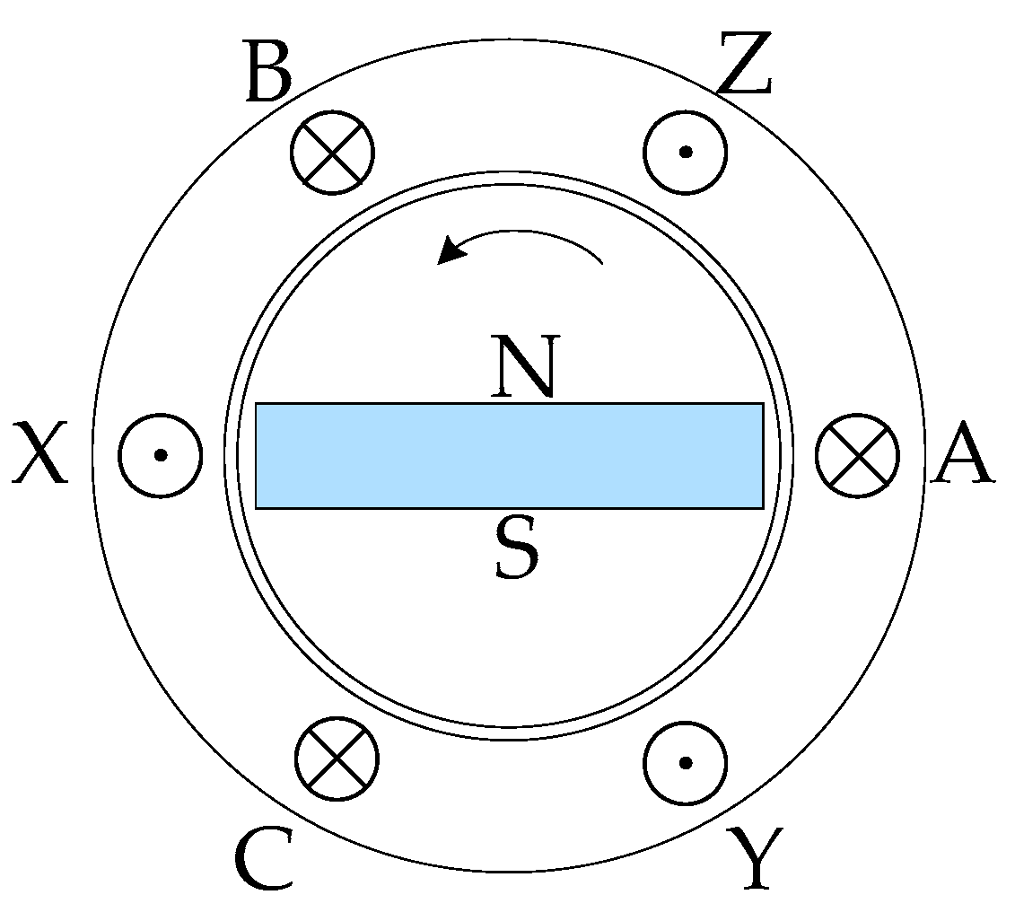
2. Relationship of Phase Inductances and Rotor Position
An ideal structure of an IPMSM is shown in
Figure 1, and the self-inductances and mutual-inductances of IPMSM can be expressed as (1) [
15], taking phase A and B as an example.
where
is air permeability,
r is stator inner diameter,
l is iron core axial length,
is rotor position in electrical angle,
and
are equations of windings A and B, and
is air gap equation. For simplification of the analysis, the influences of ferromagnetic material saturation and winding harmonic are ignored, and the equivalent air gap length is supposed to vary sinusoidally with rotor position. Taking the axis of winding A as zero position, the self-inductances (
,
,
) and mutual-inductances (
,
,
,
,
,
) of an IPMSM can be expressed as
where
is the inductance component caused by the air-gap magnetic field,
is the armature leakage inductance, and
is the inductance component caused by the position changing. According to the inductance formulas [
18], the
d-axis and
q-axis inductances are
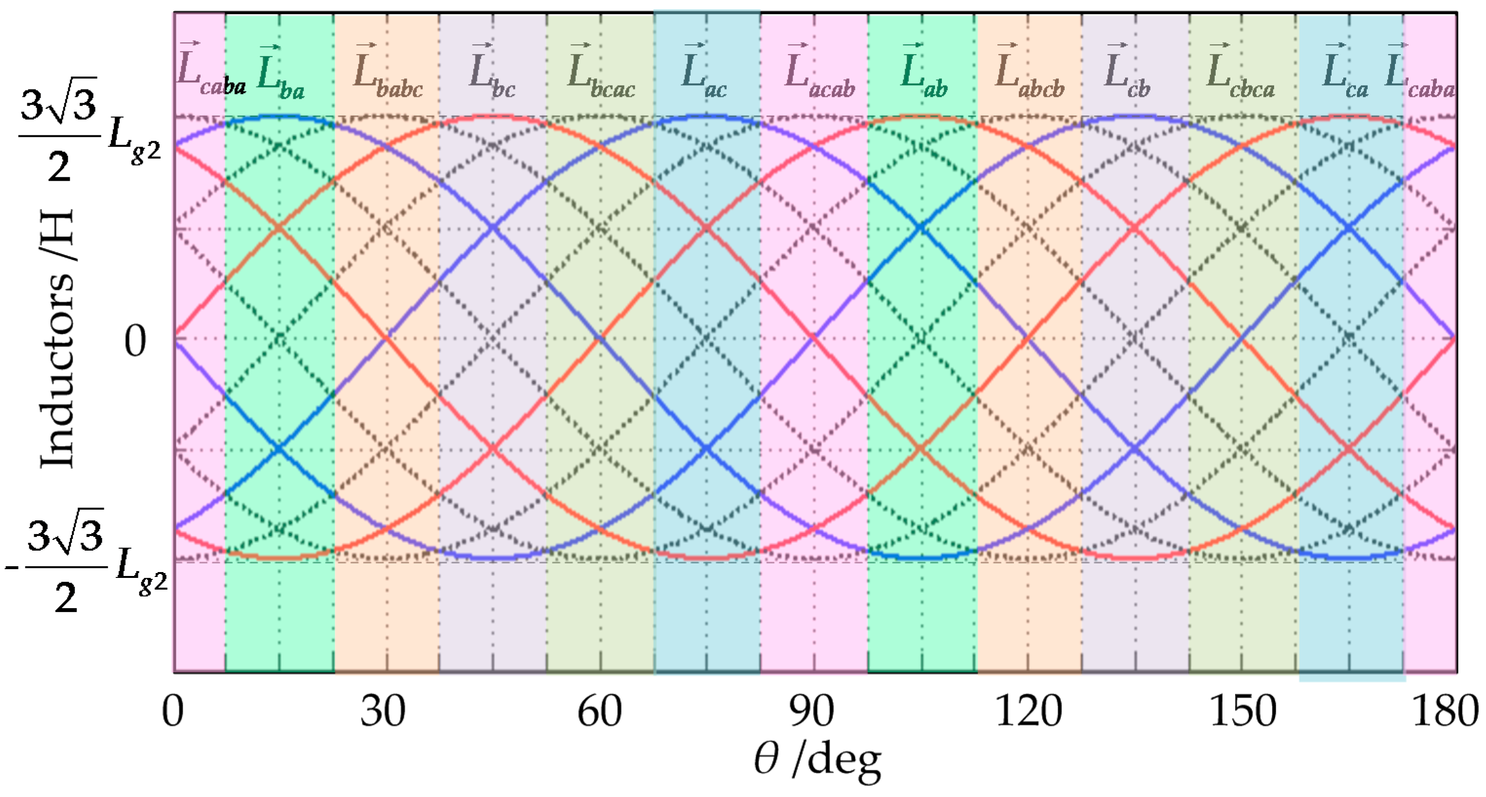
Self-inductances and mutual inductances are hard to extract or measure directly because of the coupling relationship, but the phase inductances can be detected from phase windings and used instead. The relationship between the phase inductances and rotor position can be represented with
Figure 2.
Based on the coordinate transformation principle, there exists corresponding relation between phase inductances and
d-axis and
q-axis inductances, which means the maximum value of a phase inductance corresponds to the
q-axis inductance, and the minimum value corresponds to the
d-axis inductance. Then the phase inductances are
It can be seen from
Figure 2 that the inductance contain direct component (DC) and alternating component (AC), and the rotor position is hidden in the AC component. In other words, the rotor position can be extracted from the AC component of phase inductance.
3. Proposed Position Estimation Method
With the three-phase symmetry, the difference of phase inductances is taken to eliminate zero-sequence components of DC and a three-order harmonic and its multiples,
Phase inductance errors
,
and
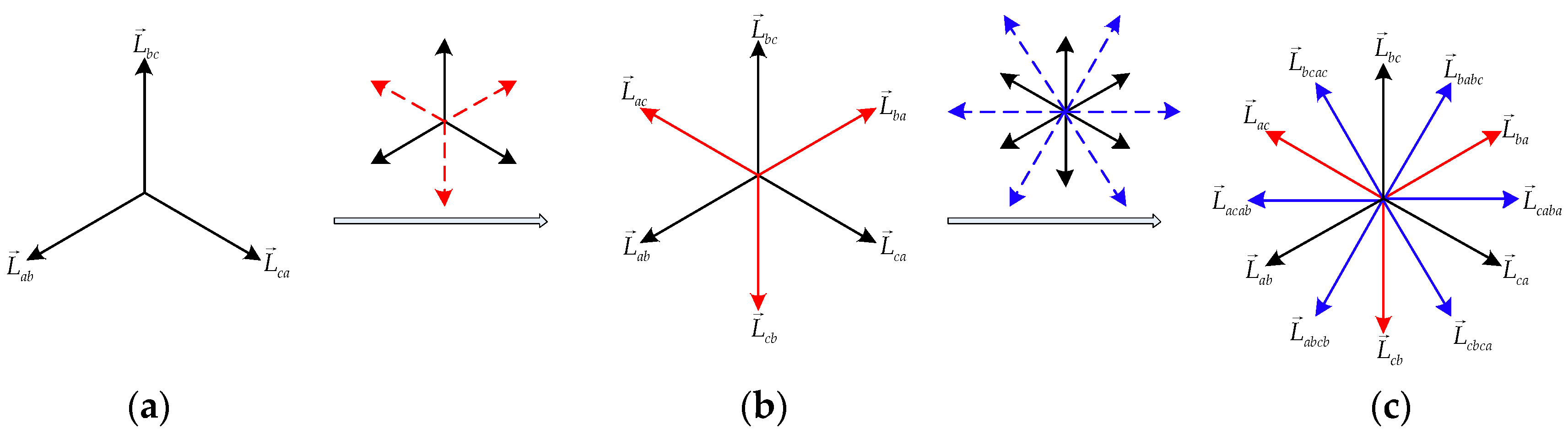
are three-phase symmetry sinusoidal waves, which means that they can be represented in vector format, as shown in
Figure 3a.
In
Figure 3a, the frequency of phase inductance error is twice of motor electrical frequency. Thus, one cycle of this position plane is
, which means this one cycle corresponds to the actual rotor position
. The position plane of 180 electrical degrees is divided into three equal parts. Adding each two neighboring vectors, six symmetrical vectors are obtained in
Figure 3b, and the position plane is divided into six equal parts. Then summing each two neighboring vectors in
Figure 3b, and multiplying by
to keep the amplitude constant, 12 symmetrical vectors are obtained in
Figure 3c, and the position plane is divided into 12 equal parts. This continues, the vectors can extend infinitely, and the position plane can also subdivide without limit, theoretically.
The propagation rule can be summarized as follows: three symmetrical vectors can be extended to
symmetrical vectors after
k (
k is a positive integer) times transformations by adding the two adjacent vectors and multiplying the sum with the decay coefficient
in every transformation, then the position plane of 180 electrical degrees is divided into
equal parts. The greater accuracy of the rotor position can be extracted from those vectors, taking
k = 2 as an example, the correspondence is shown in
Figure 4.
From
Figure 4, the rotor position range can be determined by comparing the amplitude of each inductance vector, and the relationship is shown in
Table 1.
It can be seen from
Figure 3 and
Table 1, that the position plane of 180 electrical degrees is divided into 12 equal parts, and the position resolution is 15 electrical degrees, which means the maximum position error is 7.5 electrical degrees. Taking the FOC as an example and ignoring the reluctance torque, this position error introduces about 1% ((1 − sin82.5°/sin90°) × 100%) electromagnetic torque loss based on the torque equation, which can satisfy the start requirement of an IPMSM. Furthermore, the position accuracy will rise exponentially as
k increases, and the position resolution is
electrical degrees. There is no doubt that high position accuracy is beneficial, but also brings an increase in the calculation amount. More importantly, the phase inductances of the real prototype usually contain some harmonics, which can be seen in the experiment results in
Section 5. These harmonics introduce inherent position errors, in this situation it is not necessary to choose a large iteration number
k, and the
k is appropriate if the position error caused by the iteration number is less than the inherent position error, which is beneficial for reducing the computational load.
Although the above position estimation method contains just some simple multiplication, addition and comparison calculations, however, as the
k increases, the calculation times of multiplication
Nmulti, addition
Nadd and comparison
Ncomp also increase exponentially, which can be expressed as
Besides the calculation time, the number of variables also increases exponentially, and the expression is . Taking the condition of k = 4 as an example, the whole process needs 45 multiplication and addition calculations, and 23 comparison calculations, and the number of variables is 48. To decrease the calculation time and variable number, a simplified implementation is necessary.
The key to simplified implementation is abandoning the useless vectors by immediate comparison in the iterative calculation process, which is illustrated in
Figure 5. For example, in the first step
k = 1, the maximal inductance vector is obtained by comparing the amplitudes of vectors
,
and
. Suppose that
has a maximum amplitude, then vectors
and
are obtained by adding
and
,
and
separately (or reversing the
and
directly), as shown in
Figure 5a. The multiplication calculation can be omitted because decay coefficient is 1 as
k = 1. This step takes two addition, multiplication and comparison calculations. In next step
k = 2, comparing among
,
and
, and supposing the
has maximum amplitude, the
and
are useless to subsequent calculations, so these two vectors can be discarded. Then vectors
and
are obtained by adding
and
,
and
separately, two sums are necessary to multiply by
for same amplitude, as shown in
Figure 5b. This step takes two addition, multiplication and comparison calculations.
From this example, the propagation rule of simplified implementation can be summarized as follows: in each step, the maximum vector is obtained by comparing the instantaneous values of three adjacent inductance vectors first. The maximum vector adds the two adjacent inductance vectors separately. The two sums multiply the decay coefficient to keep the same amplitude. Then the maximum vector and the two sums form the new three adjacent inductance vectors, and so on. This simplified implementation could significantly reduce the calculation time and variable number, which can be expressed as
The variable number is always five. Taking the condition of k = 4 as example, there are just eight multiplication and addition calculations, and comparison calculations in the whole process. The calculation time and variable number reduction of the simplified implementation is helpful to improve its practicality.
The IPMSM position estimated method mentioned above is different from other methods. The main reasons are:
In this method, the rotor position information is irrelevant to the specific phase inductance data, and it is only related to the amplitude relationship of the inductance vectors. In consequence, this method is not sensitive to the change of phase inductances in the same way, caused by load variation, as long as the IPMSM retains a certain saliency.
In this method, the position estimation accuracy is adjustable using iteration parameter changes for different applications.
This method does not need complex coordinate transformation and a tracking observer, it is simple and reliable, and can even be implemented with a simple programmable logic device.
4. Implementation of Proposed Method
As shown in
Figure 6, a control system based on FOC was built to validate the validity of the position estimated method above. This system mainly contains a power unit, current signal filtering unit, motor variable calculation unit and FOC unit. The power unit contains a power module and an IPMSM.
In addition to the regular FOC system, a current signal filtering unit is introduced to obtain the inductance message using the HF voltage signal injection method. The HF voltage signals
and
are produced by the power module, which is
where
and
are the amplitude and frequency of HF voltage signals. In the FOC unit,
ng and
n are given speed and feedback speed,
iqg and
iq are
q-axis given current and feedback current,
idg and
id are
d-axis given current and feedback current,
ud and
uq are
d-axis and
q-axis voltages produced by each current loop, and
and
are
α-axis and
β-axis voltages are calculated using coordinate transformation. The
and
are added to
and
, respectively, then the voltage sums are send to the space vector pulse width modulation (SVPWM) module to generate driver signals. Phase currents
and
are detected by current sensors, which contain high and low frequency (LF) current components. Band-pass filters are introduced to extract HF current signals, and HF current amplitudes
Iah,
Ibh,
Ich are obtained from absolute values. The normal LF current signals
ilfa,
ilfb,
ilfc are extracted with low-pass filters.
Ignoring the influence of the winding resistor, instantaneous values of phase inductances can be calculated with HF current amplitudes:
Then the position information can be estimated with the above method using these phase inductance values, as shown in the motor variable calculation unit of
Figure 6. The initial magnet polarity and rotor position estimation is necessary because the phase inductance frequency is twice the motor electrical frequency, and a voltage pulse injection method is employed [
19]. Once the rotor position
θ is obtained, the rotor speed,
d-axis and
q-axis currents can be calculated naturally, all of these variables are necessary for FOC operation.
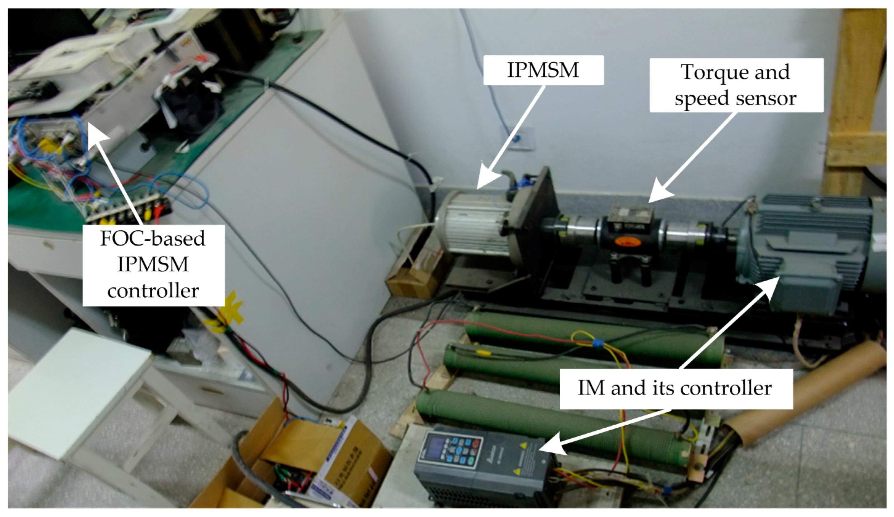
5. Experiments and Analysis
The experimental platform used in this paper is shown in
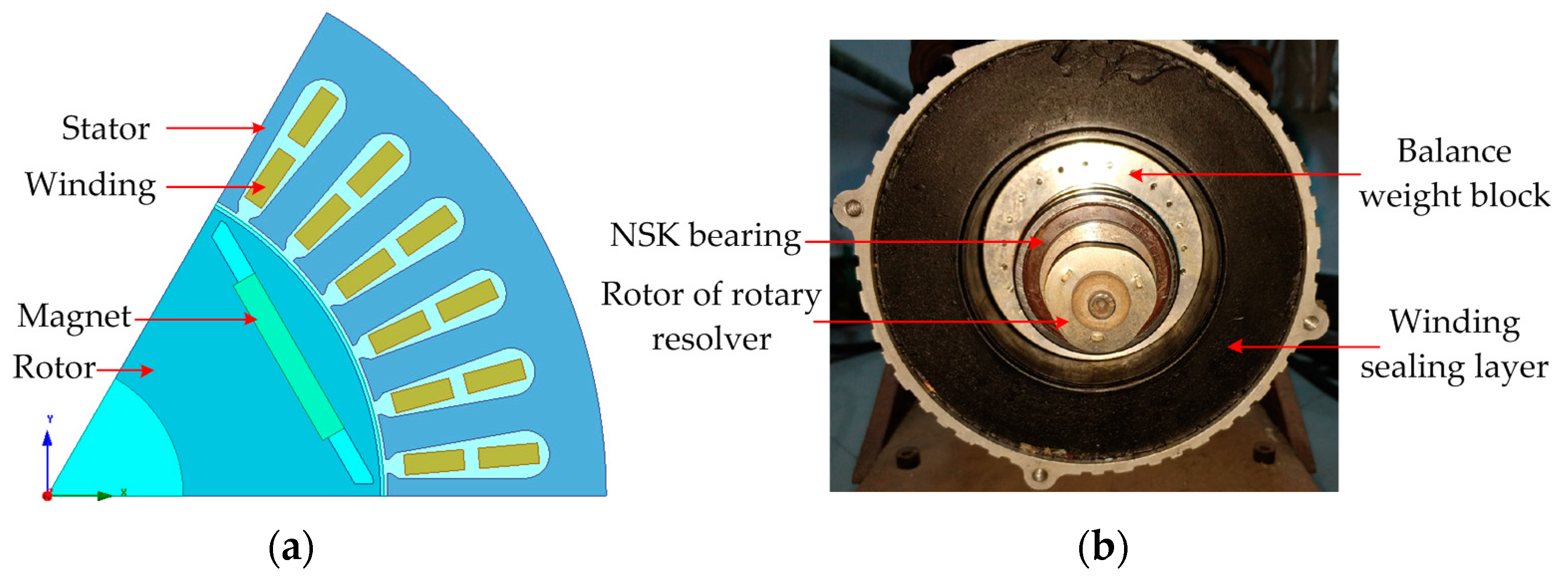
Figure 7. It contains an IPMSM, an induction motor (IM) and their controllers. A speed/torque measuring instrument is installed between the axles of the IPMSM and IM to detect the actual speed and torque. The rated value of the IM is 5.5 kW, and 1500 rpm. The parameters of the IPMSM are listed in
Table 2, and the structure of this IPMSM is shown in
Figure 8.
The proposed position estimated method was implemented on a MC56F8346 digital signal processor (DSP) (Freescale Semiconductor, Austin, TX, USA), and the control period was 125 microseconds. Variables stored in the DSP were observed from the serial port using the real-time debugging tool FreeMaster (Freescale Semiconductor, Austin, TX, USA). The actual rotor speed and position for observation were obtained from a 4096 pulses rotary resolver (Tamagawa Seiki, Nagano Prefecture, Japan). The IM plays the role of load, which supplies the variable or constant load for the IPMSM. The IPMSM operates in speed control mode, the output energy of which is absorbed by the IM and its bleeder resistor. Since the position estimated methods using HF signal injection can hardly be applied to a high speed motor, all experiments in this paper are under low speed.
5.1. Phase Inductance
Phase inductance is the basis of the proposed method.
Figure 9 shows the phase inductance waveforms of the prototype IPMSM under no load and rated load state.
It can be seen from
Figure 9 that the phase inductance can also show the magnet saliency, due to the correspondence between the phase inductances and the
d-axis and
q-axis inductances as shown in Formulas (3) and (4). Besides, the phase inductance amplitude decreases as the phase current increases, which is caused by the stator magnetic saturation.
Taking the phase inductance waveforms of the rated load as an example, the inductance vectors after two iterative calculations (
k = 2) are shown in
Figure 10. Then the rotor position can be obtained by comparing the instantaneous value of these vectors. Taking the time 0.1 s as an example and supposing the magnet polarity has been confirmed in 0° to 180° position plane. The
has the maximum amplitude in this moment, then the rotor position can be estimated in the range [37.5°, 52.5°) according to
Table 1, and the median 45° is usually chosen as the final rotor position.
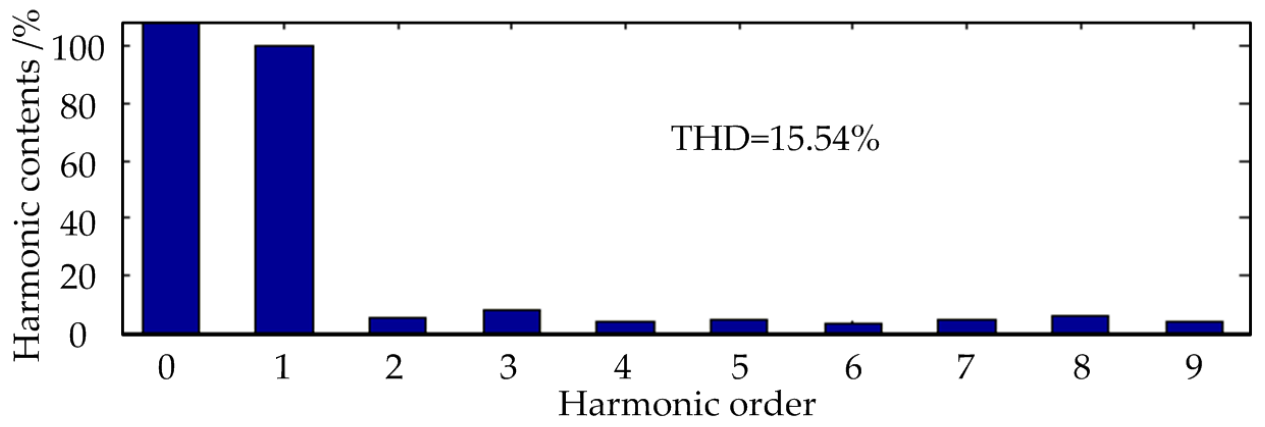
It can be seen from the
Figure 9 and
Figure 10 that these phase inductances contain some harmonics, which is due to reasons such as partial saturation, cogging effect, and so on. The total harmonic distortion (THD) of the phase inductance under rated load is 15.54%, as shown in
Figure 11.
The zero-sequence components of DC and three-order harmonic and its multiples can be eliminated with the proposed method, but the position errors caused by the remaining two, four, five and other order harmonics are added together, shown in the experiment below.
5.2. Steady State Operation Experiment
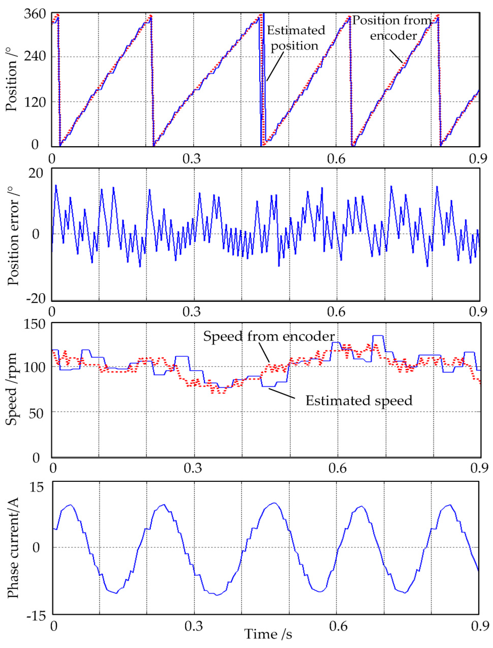
Figure 12 shows the steady state operation experiment waveforms of the prototype IPMSM under rated load state at the speed of 100 rpm.
It can be seen that the IPMSM works stably with the position estimation method, and the phase current is near-sinusoidal after filtering the HF component. The position error is about ±10°, which is slightly larger than the theoretical maximum error ±7.5° (k = 2) because of the not ideal phase inductance waveforms. The proposed method can be implemented as long as phase inductances keep a certain symmetry and saliency.
5.3. Dynamic State Operation Experiment
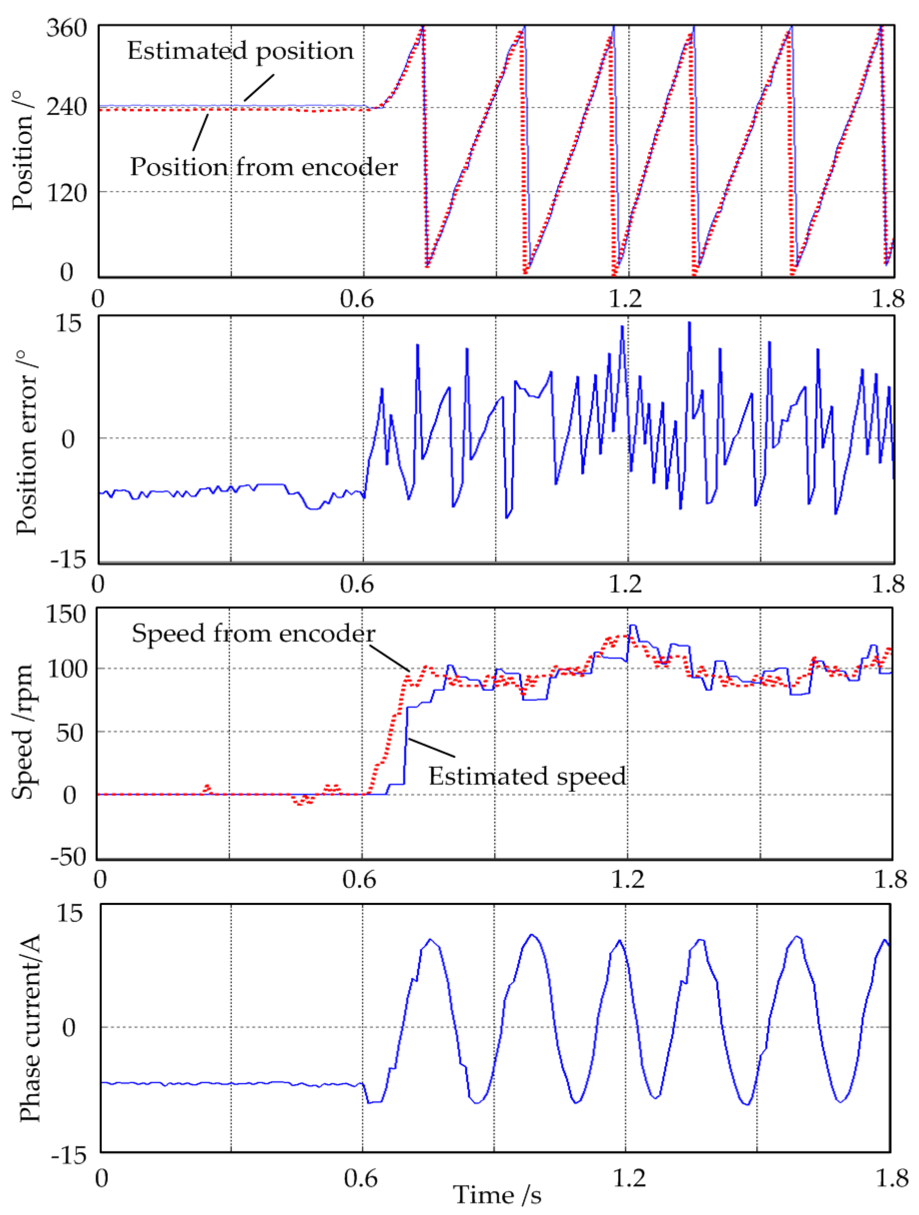
Figure 13 shows the dynamic-state operation experiment waveforms of the prototype IPMSM under the rated load state as the given speed step increases from 0 to 100 rpm at 0.6 s.
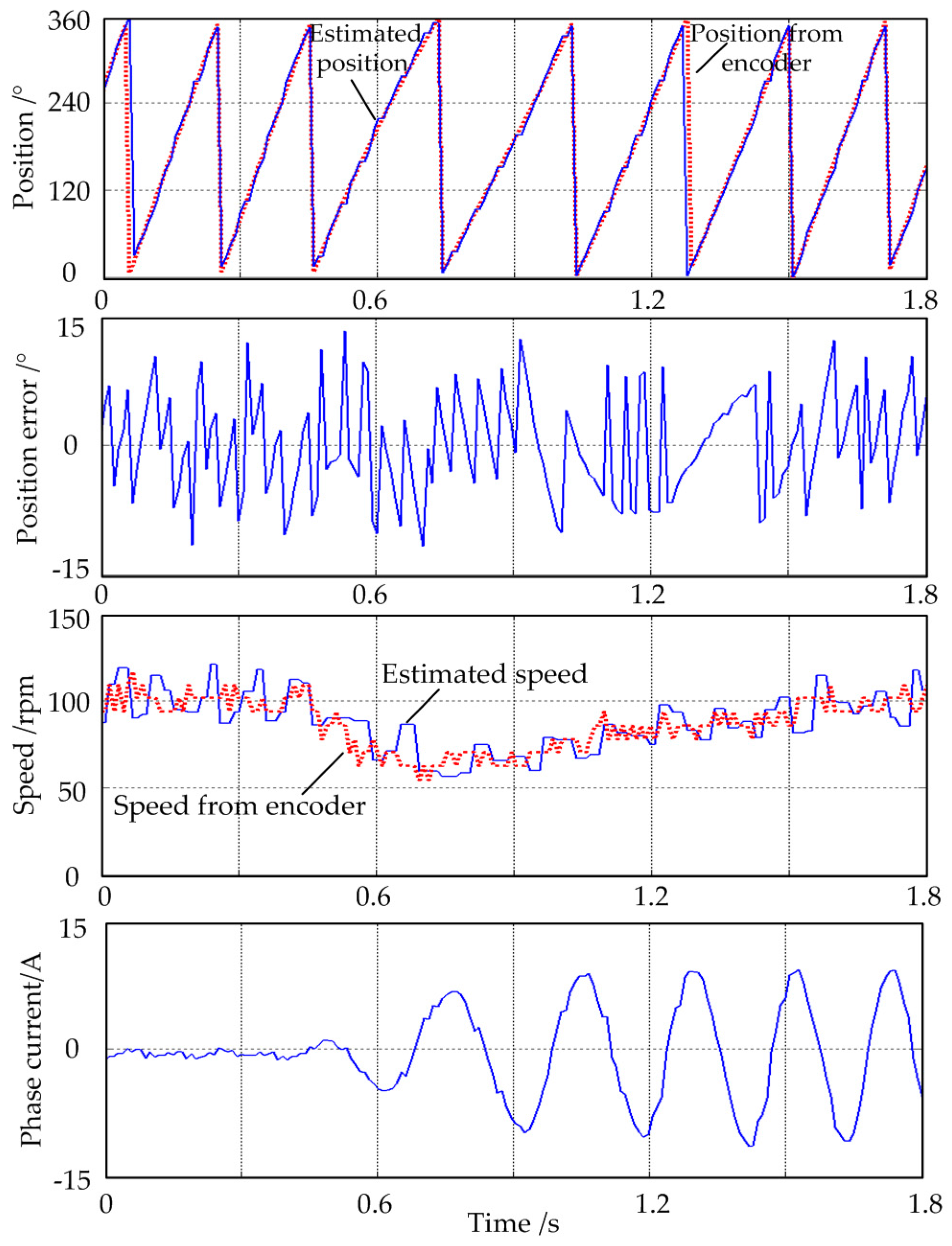
Figure 14 shows the dynamic state operation experiment waveforms of the prototype IPMSM at a speed of 100 rpm as the load torque step increases from 0 to 10 Nm at 0.4 s.
From
Figure 13 and
Figure 14, it can be seen that the position estimation method works well under dynamic operation. The IPMSM can work in zero speed conditions, and starts steadily under rated load, as shown in
Figure 13. The IPMSM works well under the variable load condition, as shown in
Figure 14. The speed loop response time is slightly long at low speed because the theoretical position accuracy of 7.5 electrical degrees is low, however, the low position accuracy results from the non-ideal phase inductance waveforms. In other words, this position estimation method can adjust the position resolution according to the phase inductance condition and system control requirements.
6. Conclusions
In this paper, a position-estimated method based on phase inductance for IPMSMs was proposed. According to the corresponding relationship of the rotor position and the phase inductance, the subdivision process of inductance vectors to divide the position plane was studied, and then the proposed position estimated method was obtained. To reduce the calculation amount, a simplified implementation was also provided.
This proposed position estimated method has following important features. (1) It is easy to implement because it only needs some fundamental math operations and logical comparisons without any coordinate transformation or trigonometric function calculations; (2) The estimation precision can be adjusted according to the motor inductance condition and control requirements to save the calculating resource; (3) It is not sensitive to the change of phase inductances in the same way, as long as the IPMSM retains a certain saliency, so its reliability and adaptability is relatively good.
As a new position-estimated method, there are many aspects that need to be studied in the future, such as the improvement of position estimation accuracy and stability from the point of motor optimal design, the combination of this method and control strategy, the engineering practice of this method in different industrial applications, and so on.


