New Hybrid Static VAR Compensator with Series Active Filter
by
Ayumu Tokiwa
1, 
Hiroaki Yamada
1,
Toshihiko Tanaka
1,*,
Makoto Watanabe
2,
Masanao Shirai
2 and
Yuji Teranishi
2 1
Department of Electrical and Electronic Engineering, Yamaguchi University, 2-16-1 Tokiwadai, Ube, Yamaguchi 755-8611, Japan
2
The Chugoku Electric Manufacturing Company, Incorporated, 4-4-32 Minamiku Osu, Hiroshima 732-8564, Japan
*
Author to whom correspondence should be addressed.
Energies 2017, 10(10), 1617; https://doi.org/10.3390/en10101617
Submission received: 7 August 2017
/
Revised: 28 September 2017
/
Accepted: 10 October 2017
/
Published: 16 October 2017
(This article belongs to the Special Issue Power Electronics and Power Quality)
Abstract
:This paper proposes a new hybrid static VAR compensator (SVC) with a series active filter (AF). The proposed hybrid SVC consists of a series AF and SVC. The series AF, which is connected in series to phase-leading capacitors in the SVC, performs for a resistor for source-side harmonic currents. A sinusoidal source current with a unity power factor is obtained with the series AF, although the thyristor-controlled reactor generates harmonic currents. A digital computer simulation was implemented to confirm the validity and high practicability of the proposed hybrid SVC using PSIM software. The simulation results demonstrate that sinusoidal source currents with a unity power factor are achieved with the proposed hybrid SVC.
1. Introduction
Large-capacity electric arc furnaces and rolling mills cause rapid reactive-power fluctuations in distribution feeders. These rapid reactive-power fluctuations lead to reactive-power interferences such as flickers and voltage fluctuations in distribution feeders. Static VAR compensators (SVCs) with thyristor-controlled reactors (TCRs) and phase-leading capacitors (PLCs) are widely used to solve the reactive-power interferences in distribution feeders because of low costs [1]. However, TCRs generate harmonic currents on the source side [2]. Many topologies have been proposed to improve the compensation characteristics of the source-side harmonic currents for SVCs [3,4,5,6]. The passive filters, which consist of the 5th-, 7th-, and 11th-tuned filters, are combined with the TCR. A three-phase current-controlled voltage-source pulse-width-modulated (PWM) inverter is connected in series to the passive LC filters through matching transformers (MTs). The series-connected three-phase current-controlled voltage-source PWM inverter improves the compensation characteristics of the passive filters.
Hybrid active filters (AFs) have also been proposed by many researchers [7,8,9,10,11]. The previously proposed hybrid AF topologies are essentially a series connection of the LC tuned filters and a three-phase shunt AF. The rating of the shunt AF can be reduced because the fundamental reactive and designated-order harmonic currents are compensated for by the series-connected LC tuned filters. A hybrid SVC topology with the hybrid AF has been proposed [12,13]. The PLCs with TCRs control the fundamental reactive power on the source side. As the shunt AF compensates only for harmonic currents, the required rating of the shunt AF is low. In [14], a static synchronous compensator (STATCOM) is combined with TCRs. The STATCOM performs with PLCs compensating for harmonic currents on the source side. Thus, the required rating of the parallel-connected STATCOM is high. A combined system of shunt-passive and series AFs has also been proposed [15,16,17]. While the proposed topologies are practical and cost-effective, the fundamental reactive power on the source side cannot be controlled. Thus, a hybrid SVC topology consisting of TCRs and pure PLCs with a small-rated voltage-source PWM inverter has not been reported, as far as the authors know.
This paper proposes a new hybrid SVC topology comprising a small-rated series AF and SVC, which consists of TCRs and pure PLCs. The series AF is connected in series to the pure PLCs. In [17], Prof. H. Fujita, et al. proposed a combined system consisting of a shunt-passive filter and series AF for a current-source harmonic-producing load. The series AF performs for a resistor of for source-side harmonic currents. We note that there are two current-source harmonic-producing loads, namely, the TCR and the three-phase load, in the newly proposed hybrid SVC. Considering both the three-phase load and the TCR as a current-source harmonic-producing load, the previously proposed control strategy for the series AF in [17] is applicable to the newly proposed hybrid SVC. This is a simple and practical idea for the control strategy of the series AF in the newly proposed hybrid SVC. Thus, the series AF in the proposed hybrid SVC performs for a resistor of for source-side harmonic currents. The source-side harmonic currents are isolated by the series AF, while PLCs with TCRs compensate for the fundamental reactive currents on the source side. Sinusoidal source currents with a unity power factor are achieved by the newly proposed hybrid SVC. The basic principle of the proposed hybrid SVC is discussed in detail. The compensation characteristics of the harmonic currents are shown in detail, and these have been confirmed by digital computer simulation using PSIM software. The simulation results demonstrate that sinusoidal source currents with a unity power factor are obtained. From the simulation results, the required capacity of the series AF is 2.8% as compared to the rating of the three-phase load. The addition of the small-rated series AF isolates the source-side harmonics perfectly. Only the newly proposed topology can be applied to the SVCs that are under commercial operations, although the required rating of the series AF is slightly higher than that of the series AF in [3,4,5,6]. This demonstrates that the proposed hybrid SVC is useful and cost-effective for practical distribution feeders.
2. Previously Proposed Topologies of the Hybrid Static VAR Compensator
Figure 1 shows a power circuit diagram of the previously proposed hybrid SVC topology [3,4,5,6]. The previously proposed hybrid SVC topology consists of TCRs and 5th-, 7th-, and 11th-tuned filters with series-connected AFs. In [3], the added series AF performs for a resistor for the source-side currents. The purpose of the series AF is to suppress the anti-resonance between the LC tuned filters and source impedance.
The source-side harmonic current compensations with the series AF under normal operation were not discussed or demonstrated. In [4,5,6], the added series AFs perform as current sources for harmonic currents, which flow into the LC tuned filters. This injection improves the compensation characteristics of the LC tuned filters. The required rating of the series AF was 1.4% as compared to the rating of the three-phase load. The previously proposed hybrid SVC topology in Figure 1, however, cannot be applied to the SVCs that are under commercial operations, because PLCs should be replaced by the LC tuned filters.
Figure 2 shows a power circuit diagram of the previously proposed hybrid SVC topology [12,13]. The PLCs with TCRs control the fundamental reactive power on the source side. The inductors are connected in series to the PLCs with TCRs. These allow the fifth-tuned LC filters to sink the fifth-harmonics generated by the load. The shunt AFs inject the harmonic currents. Thus, the shunt AFs improve the compensation characteristics of the fifth-tuned filters. The required rating of the shunt AFs was 4.0% as compared to the rating of the three-phase load. The previously proposed hybrid SVC topology is not applicable to the SVCs that are under commercial operations, because the conventional PLCs with TCRs also should be replaced with those shown in Figure 2.
Figure 3 shows a power circuit diagram of the previously proposed hybrid SVC with the STATCOM [14]. The STATCOM performs with PLCs compensating for harmonic currents on the source side. Thus, the required rating of the parallel-connected STATCOM is much higher than those of the added AFs in Figure 1 and Figure 2. In [14], the required rating of the STATCOM is 80% as compared to the rating of the three-phase load. Using a large capacity, the STATCOM results in a high-cost hybrid SVC.
Table 1 shows summaries of the previously proposed hybrid SVC. As described in the Introduction, a hybrid SVC topology with a small-rated voltage-source PWM inverter, which can be applied to the conventional SVC consisting of TCRs and pure PLCs, has not been reported, as far as the authors know.
3. Newly Proposed Hybrid Static VAR Compensator
Figure 4 shows a circuit diagram of the proposed hybrid SVC. Table 2 shows circuit constants for Figure 4, which are used in the following simulation results. The proposed hybrid SVC comprises a series AF and SVC, which consists of the -connected TCR and -connected pure PLCs. The series AF consists of a three-phase voltage-source PWM inverter with insulated-gate bipolar transistors (IGBTs). The series AF is connected in series to the three-phase PLCs through MTs, where the turns ratio is 1:2. The small-rated LC filter (inducer and capacitor ) suppresses switching ripples that are generated by the PWM inverter, which performs for the series AF. The purpose of this paper is to demonstrate the compensation performance of the reactive and harmonic currents for the proposed hybrid SVC. Thus, ideal models for IGBTs, inductors, and capacitors are used. Table 3 shows data for the MTs used in Figure 4. Leakage inductors, winding resistors, and magnetizing admittance are considered in the MT model of Figure 4. A three-phase load generates the fundamental reactive currents, and fifth- and seventh-order harmonic currents. A three-phase current source is used to demonstrate the three-phase load. The authors, who are with the Chugoku Electric Manufacturing Company, have had extensive experience with developing commercial SVCs and selling SVCs to customers. Generally, the capacities of TCRs and PLCs are decided by considering the true load conditions of the customers. Thus, the capacities of TCRs and PLCs were decided with the published paper [18].
The rating of the three-phase load is 176 MVA. The rating of the three-phase source voltage is 33 kVrms, 60 Hz, while the rating of the inductor of the TCRs is 80 MVA and that of the PLCs is 140 MVA. Thus, the per-phase base rated current and impedance are 3.1 kArms and 6.2 , which are both 1 pu. The pure PLCs with TCRs compensate for the fundamental reactive power on the source side. The series AF performs for a resistor of . The source-side harmonic currents are isolated by the series AF, while PLCs with TCRs compensate for the fundamental reactive currents on the source side. Sinusoidal source currents with a unity power factor are achieved by the newly proposed hybrid SVC.
Figure 5 shows per-phase equivalent circuits for Figure 4. Figure 5a shows a per-phase equivalent circuit for Figure 4, where is the source voltage, is the source current, is the load current, is the TCR current, is the PLC current, is the output value of the series AF, is the source-side impedance, and is the impedance of a per-phase PLC. The three-phase load generates the fundamental reactive currents and harmonic currents. TCRs with PLCs compensate for the fundamental reactive currents. However, TCRs also generate harmonic currents. Thus, there are two current-source harmonic-producing loads, namely, the TCR and three-phase load, in Figure 5a. Harmonic currents generated by both the three-phase load and TCRs flow into PLCs and the source voltage . Thus, the three-phase load and TCRs are considered by a current-source harmonic-producing load. Figure 5b shows a per-phase equivalent circuit for Figure 5a, where is the sum of generated by the TCR and generated by the three-phase load. Professor H. Fujita et al. proposed a combined system of a shunt-passive filter and series AF for the current-source harmonic-producing load, which is a large-capacity thyristor rectifier, with a novel control method of the series AF [17]. The control method proposed in [17] is applicable for Figure 4 because two current-source harmonic-producing loads, namely, the TCR and three-phase load, can be considered as a current-source harmonic-producing load, as shown in Figure 5b. The series AF performs for a resistor of for the harmonic source currents. The output voltage of the series AF in Figure 5b is given by
When no harmonics are included in the source voltage , a per-phase base equivalent circuit for load-side harmonic currents is shown in Figure 5c. In Figure 5c, the source-side harmonic current is given by
If in Equation (2),
Thus, the sinusoidal source currents , , and are obtained with the series AF connected to the pure PLCs. The transfer function G(s) of the low-pass filter (LPF) in Figure 4 is considered in Equation (2). The transfer function G(s) of the LPF is expressed as
where . The cut-off frequency is 179 Hz, and the damping factor is 0.7. With the transfer function G(s), the source-side harmonic currents are rewritten as
Figure 6a shows gain plots for Figure 5c, where the source-side impedance pu. In Figure 6, is the source-voltage frequency, which is 60 Hz. As described before, the per-phase rated impedance is 6.2 in Figure 4. To satisfy that in Equation (2), the control gain is varied from 10 to 30 . The line with shows the compensation characteristics for the source-side harmonic currents when the series AF is not connected. From the second- to fifth-order components, the gains are positive. This means that the harmonic currents generated by the TCRs and three-phase load are magnified on the source side. Increasing the control gain suppresses the harmonic current magnifications on the source side. In particular, when is 30 , there is no positive area for the fundamental and harmonic components. Thus, the series AF with the control gain of 30 perfectly isolates the harmonic currents generated by both the TCRs and the three-phase load on the source side. The sinusoidal source currents with a unity power factor are obtained with the proposed hybrid SVC.
Figure 5d shows a per-phase base equivalent circuit for the source-voltage harmonics . In Figure 5d, is expressed by
Figure 6b shows gain plots for Figure 5d. The line with shows the compensation characteristics for the source-side harmonic voltages when the series AF is not connected. From the third- to fourth-order components, the source-side harmonic current flows into the PLC. The lines with show the compensation characteristics for the source-side harmonic voltages with the series AF. The source-side harmonic currents are isolated by the series AF in the proposed hybrid SVC. Therefore, sinusoidal source currents with a unity power factor are obtained with the proposed hybrid SVC. We note that no fundamental source voltage appears across the series AF, and this results in a significant reduction in the required rating of the series AF.
Here, the control strategy of the series AF in the time domain, which was proposed in [17], is briefly introduced. A three-phase phase-locked loop (PLL) is used to detect the electric angle of a-phase PLC current [19]. Here, only the PLC currents are detected to generate the electric angle . The terminal voltages , , and are not detected. Thus, any sensors for the external voltages detections are not needed in the proposed hybrid SVC shown in Figure 4. The firing angle of the TCR is also controlled using the electric angle .
The source currents , , and are expressed as
Three-phase source currents, , , and are detected, and then the detected source currents are transformed into d-q coordinates. Generally, to transform , , and into d-q coordinates, the electric angle of a-phase terminal voltage is required. In Figure 4, + equals . Using the detected electric angle , and can be calculated; and are given by
The DC components and in d-q coordinates originate from the fundamental components , , and of the source currents , , and , respectively, in a-b-c coordinates. The AC components and in d-q coordinates originate from the harmonic currents , , and of the source currents. These AC components are extracted by high-pass filters (HPFs) with a second-order LPF. The extracted AC components are then retransformed into a-b-c coordinates. Retransforming and into a-b-c coordinates gives the source-side harmonic currents , , and . With the extracted source-side harmonic currents , , and , the reference values , , and for the series AF are given by
Therefore, the series AF performs for a resistor of for source-side harmonic currents , , and . A sine-triangle intercept technique is used to generate the gate signals for the three-phase voltage-source PWM inverter. The switching frequency of the three-phase voltage-source PWM inverter is 12 kHz.
4. Simulation Results
The validity and high practicability of the proposed hybrid SVC were confirmed by digital computer simulation using PSIM software. PSIM is an electronic circuit simulation software package, designed specifically for use in power electronics and motor drive simulations [20]. PSIM is developed and released by Powersim [21].
The root-mean-square (RMS) value of the fundamental components of the load currents is 3.1 kArms. The fifth-order components of 334 Arms and seventh-order components of 100 Arms are also included in the load currents , , and . Thus, the total harmonic distortion (THD) value of , , and is 11.3%, respectively. The power factor is 0.7. Circuit constants for Figure 4 shown in Table 2 are used in the following simulation results. The small-rated LC filter (inducer and capacitor ) suppresses switching ripples generated by the PWM inverter, which performs for the series AF. As shown in Figure 4, the constant DC-capacitor voltage control block is added in the control circuit for the series AF. The DC-capacitor voltage is controlled using the d-axis component in d-q coordinates of the PLC currents , , and .
Figure 7, Figure 8 and Figure 9 show simulation results for Figure 4 before/after the series AF, which is a three-phase voltage-source PWM inverter, was started. We note that the DC-capacitor voltage should be 10 kVdc, which is the reference value of 10 kVdc, before the series AF is started. The constant DC-capacitor voltage control had already started before the series AF was started, as shown in Figure 7, Figure 8 and Figure 9. Thus, the series AF was smoothly started without any transient phenomena of the small-rated LC filter ( and ).
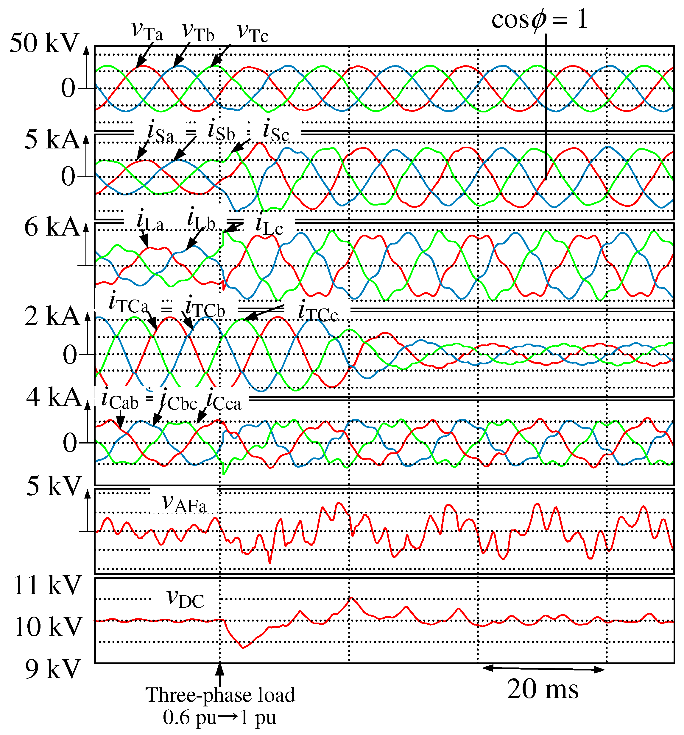
The receiving-end voltage waveforms are , , and ; , , and are the source-current waveforms; , , and are the load current waveforms; , , and are the TCR current waveforms; , , and are the PLC current waveforms; is an a-phase output-voltage waveform of the series AF; is the DC-capacitor voltage waveform.
In Figure 7, Figure 8 and Figure 9, the source currents , , and are heavily distorted because the three-phase load and TCRs generate harmonic currents and inject these to the source side. The THD value of , , and is 14.2%, respectively. In Figure 7, the source currents , , and , however, were distorted after the series AF was started. The THD values of , , and are 8.6%, 8.6%, and 8.7%, respectively. With the control gain of 10 , as shown in Figure 6, the insufficient compensation performance for harmonic currents was achieved. In Figure 8, the source currents , , and were distorted after the series AF was started. The THD values of , , and are 4.7%, 4.8%, and 4.8%, respectively. With the control gain of 20 , as shown in Figure 6, insufficient compensation performance for harmonic currents was achieved. In Figure 9, the source currents , , and were sinusoidal with a unity power factor after the series AF was started. The THD values of , , and are 3.0%, 3.1%, and 3.2%, respectively. As shown in Figure 6, the sufficient compensation performance for harmonic currents was achieved with the control gain of 30 . The DC-capacitor voltage was well controlled to its reference value = 10 kVdc. The ripple of the DC-capacitor voltage was 3.0% in the transient state and ± 1.0% in the steady state.
Figure 10 shows spectra of a-phase source current . When the series AF was not started, when , the RMS value of the fifth-order harmonics was 336 Arms and the seventh-order harmonics was 36.8 Arms. A higher control gain achieves sufficient compensation characteristics for source-side harmonic currents.
Figure 11 shows the simulation results for Figure 4 with the three-phase load variation from 0.6 to 1.0 pu, where the control gain was 30 . The per-phase base rated current was 3.1 kArms. Thus, each phase current of the three-phase load was varied from 1.86 kArms, which is 0.6 pu, to 3.1 kArms, which is 1 pu. Before and after the load variations, the source currents , , and were sinusoidal with a unity power factor. The DC-capacitor voltage was well controlled to its reference value = 10 kVdc. The ripple of the DC-capacitor voltage was 7.0% in the transient state and ±1.0% in the steady state.
In the simulation results of Figure 7, Figure 8 and Figure 9 and Figure 11, no harmonic voltages in the three-phase source voltages were considered. However, harmonics are included in the true high-voltage three-phase distribution feeders [22]. As shown in Figure 6b, harmonic currents flow into the PLCs if the source voltages are distorted. Thus, it is desirable that the series AF is always under operation despite a few switching losses are caused by the series AF, which consists of IGBTs.
The required rating of the three-phase voltage-source PWM inverter, which performs for the series AF, is now calculated. The required rating is expressed as
where , , , , , and are all RMS values. From the simulation results shown in Figure 9, = 4.96 MVA. This is 2.8%, as compared to the rating of the three-phase load. The addition of the small-rated three-phase and low-cost voltage-source PWM inverter significantly improves the power quality on the source side.
5. Comparisons between the Newly Proposed Topology and Previously Proposed Topologies
Table 1 has summarized the previously proposed hybrid SVC topologies. It is desirable that the rating of the added power converter, which performs for the AF or STATCOM, is low from the viewpoint of the cost. Although a topology as shown in Figure 3 achieves excellent compensation characteristics of fundamental reactive and harmonic currents with a more rapid response than those of the other topologies of Figure 1 and Figure 2, the large-capacity STATCOM with a high price is required. In the previously proposed topology shown in Figure 1, the required rating of the added AF is only 1.4% as compared to that of the three-phase load. However, LC tuned filters are required rather than pure PLCs. This means that the previously proposed topology shown in Figure 1 cannot be applied to the SVCs that are under commercial operations. The topology of Figure 2 also cannot be applied to the SVCs that are under commercial operations. Only the newly proposed topology can be applied to the SVCs that are under commercial operations, although the required rating of the series AF is slightly higher than that of the series AF in Figure 1. As described in Section 3, a three-phase PLL is used to detect the electric angle of a-phase PLC current. Only the PLC currents are detected, and any sensors for the external voltages and currents are not needed in the proposed hybrid SVC shown in Figure 4. This also demonstrates that the newly proposed topology can be applied to the SVCs that are under commercial operations. The authors thus conclude that the proposed hybrid SVC is useful and cost-effective for practical distribution feeders.
6. Conclusions
This paper has proposed a new hybrid SVC topology comprising a series AF and SVC, which consists of TCRs and pure PLCs. The series AF is connected in series to the pure PLCs. The series AF performs for a resistor for source-side harmonic currents. A sinusoidal source current with a unity power factor is obtained. Any sensors for the external voltages and currents are not needed in the proposed hybrid SVC. The basic principle of the proposed hybrid SVC has been discussed in detail. The compensation characteristics of the harmonic currents have been shown and were confirmed by digital computer simulation using PSIM software. Simulation results have demonstrated that the sinusoidal source currents with a unity power factor are obtained. From the simulation results, the required-capacity of the series AF is 2.8% as compared to the rating of the three-phase load. Only the newly proposed topology can be applied to the SVCs that are under commercial operations, although the required rating of the series AF is slightly higher than that of the series AF in [3,4,5,6]. It is thus concluded that the proposed hybrid SVC is useful and cost-effective for practical distribution feeders.
Author Contributions
Ayumu Tokiwa significantly contributed to demonstrate the basic principle of new hybrid static var compensator with series active filter and contributed to the design of the proposed circuit topology and the implementation of the digital computer simulation. Toshihiko Tanaka proposed the circuit topology and helped with the writing of this paper. Hiroaki Yamada, Makoto Watanabe, Masanao Shirai, and Yuji Teranishi were responsible for guidance and key suggestions.
Conflicts of Interest
The authors declare no conflict of interest.
References
- Chen, J.H.; Lee, W.J.; Chen, M.S. Using a static var compensator to balance a distribution system. IEEE Trans. Ind. Appl. 1999, 35, 298–304. [Google Scholar] [CrossRef]
- Xu, W.; Marti, J.R.; Dommel, H.W. Harmonic analysis of systems with static compensators. IEEE Trans. Power Syst. 2009, 6, 183–190. [Google Scholar] [CrossRef]
- Zhou, L.; Qi, S.; Huang, L.; Zhou, Z.; Zhu, Y. Design and simulation of a control system with a comprehensive power quality in power system. In Proceedings of the Electrical Machines and Systems (ICEMS), Seoul, Korea, 8–11 October 2007; pp. 376–381. [Google Scholar]
- Zhang, X.; Wang, Y.; Lei, W.; Yang, J.; Tang, X.; Si, W.; Hou, J. A comprehensive power quality controller for substations in power system. In Proceedings of the Applied Power Electronics Conference and Exposition, Dallas, TX, USA, 19–23 March 2006; pp. 1758–1762. [Google Scholar]
- Luo, A.; Shuai, Z.; Zhu, W.; Shen, Z.J. Combined system for harmonic suppression and reactive power compensation. IEEE Trans. Ind. Electron. 2009, 56, 418–428. [Google Scholar] [CrossRef]
- Luo, A.; Peng, S.; Wu, C.; Wu, J.; Shuai, Z. Power electronic hybrid system for load balancing compensation and frequency-selective harmonic suppression. IEEE Trans. Ind. Electron. 2012, 59, 723–732. [Google Scholar] [CrossRef]
- Jou, H.-L.; Wu, J.-C.; Wu, K.-D. Parallel operation of passive power filter and hybrid power filter for harmonic suppression generation. IEE Proc. Transm. Distrib. 2001, 148, 8–14. [Google Scholar] [CrossRef]
- Senini, S.; Wolfs, P.J. Hybrid active filter for harmonically unbalanced three phase three wire railway traction loads. IEEE Trans. Power Electron. 2000, 15, 702–710. [Google Scholar] [CrossRef]
- Varschavsky, A.; Dixon, J.; Rotella, M.; Moran, L. Cascaded nine-level inverter for hybrid-series active power filter, using industrial controller. IEEE Trans. Ind. Electron. 2010, 57, 2761–2767. [Google Scholar] [CrossRef]
- Luo, A.; Tang, C.; Shuani, Z.; Zhao, W.; Rong, F.; Zhou, K. A novel three-phase hybrid active power filter with a series resonance circuit tuned at the fundamental frequency. IEEE Trans. Ind. Electron. 2009, 56, 2431–2440. [Google Scholar] [CrossRef]
- Corasaniti, V.F.; Barbieri, M.B.; Arnera, P.L.; Valla, M.I. Hybrid power filter to enhance power quality in a medium-voltage distribution network. IEEE Trans. Ind. Electron. 2009, 56, 2885–2893. [Google Scholar] [CrossRef]
- Rahmani, S.; Hamadi, A.; Al-Haddad, K.; Dessaint, L.A. A combination of shunt hybrid power filter and thyristor-controlled reactor for power quality. IEEE Trans. Ind. Electron. 2014, 61, 2152–2164. [Google Scholar] [CrossRef]
- Yang, J.; Wang, Y.; Duan, Y.; Fu, Z.; Wang, Z. A three-phase comprehensive reactive power and harmonics compensator based on a comparatively small rating APF. In Proceedings of the Applied Power Electronics Conference and Exposition, Anaheim, CA, USA, 22–26 February 2004. [Google Scholar]
- Al-Mubarak, A.H.; Thorvaldsson, B.; Halonen, M.; Al-Kadhem, M.Z. Hybrid and classic SVC technology for improved efficiency and reliability in Saudi transmission grid. In Proceedings of the T&D Conference and Exposition, Chicago, IL, USA, 14–17 April 2014. [Google Scholar]
- Peng, F.Z.; Akagi, H.; Nabae, A. A new approach to harmonic compensation in power systems-A combined system of shunt passive and series active filters. IEEE Trans. Ind. Appl. 1990, 26, 983–990. [Google Scholar] [CrossRef]
- Peng, F.Z.; Akagi, H.; Nabae, A. Compensation characteristics of the combined system of shunt passive and series active filters. IEEE Trans. Ind. Appl. 1993, 29, 144–152. [Google Scholar] [CrossRef]
- Fujita, H.; Akagi, H. A practical approach to harmonic compensation in power systems-series connection of passive and active filters. IEEE Trans. on Ind. Appl. 1991, 27, 1020–1025. [Google Scholar] [CrossRef] [Green Version]
- Konishi, S.; Baba, K.; Daiguji, M. Static var compensator. Fuji Electr. J. 2001, 74, 289–295. (In Japanese) [Google Scholar]
- Arruda, L.N.; Silva, S.M.; Filho, B.J.C. PLL structure for utility connected systems. In Proceedings of the Industry Applications Conference, Chicago, IL, USA, 30 September–4 October 2001; pp. 2655–2660. [Google Scholar]
- Jin, H. Computer simulation of power electronic circuits and systems using PSIM. In Proceedings of the International Conference on Power Electronics (ICPE), Seoul, Korea, 10–14 October 1995; pp. 79–84. [Google Scholar]
- PSIM Accelerates Your Pace of Innovation. Available online: https://powersimtech.com (accessed on 16 October 2017).
- IEEE 519-2014, Recommended Practices and Requirements for Harmonic Control in Electrical Power System; IEEE: New York, NY, USA, 2014.
Figure 1.
Power circuit diagram of the previously proposed hybrid static VAR compensator (SVC) with a series active filter (AF) [3,4,5,6].
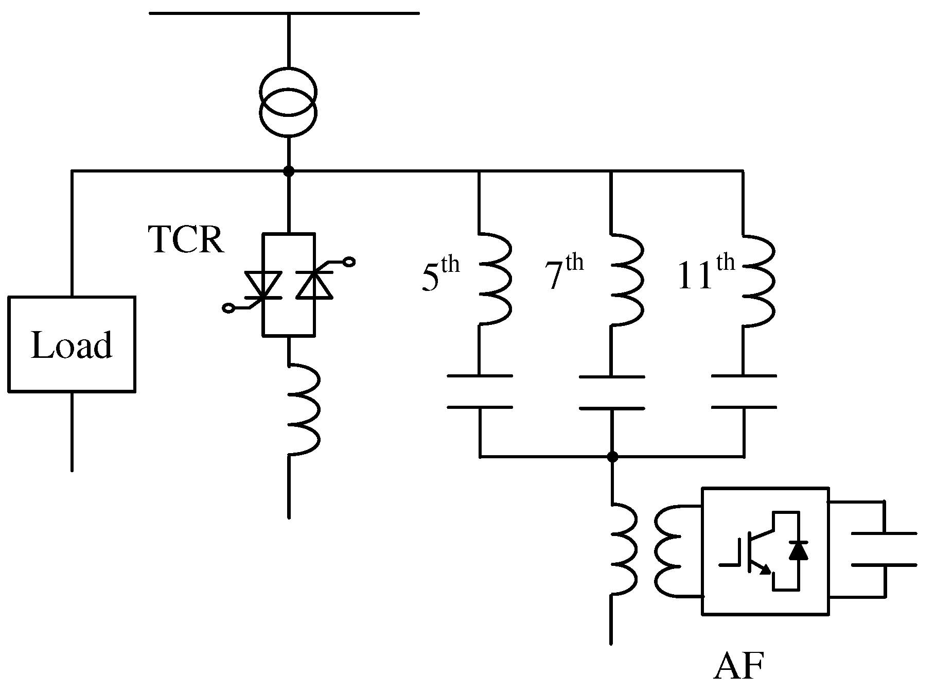
Figure 2.
Power circuit diagram of the previously proposed hybrid static VAR compensator (SVC) with thyristor-controlled reactor (TCR) and phase-leading capacitor (PLC) with series AF [12,13].

Figure 3.
Power circuit diagram of the previously proposed hybrid static VAR compensator (SVC) with a static synchronous compensator (STATCOM) [14].
Figure 3.
Power circuit diagram of the previously proposed hybrid static VAR compensator (SVC) with a static synchronous compensator (STATCOM) [14].
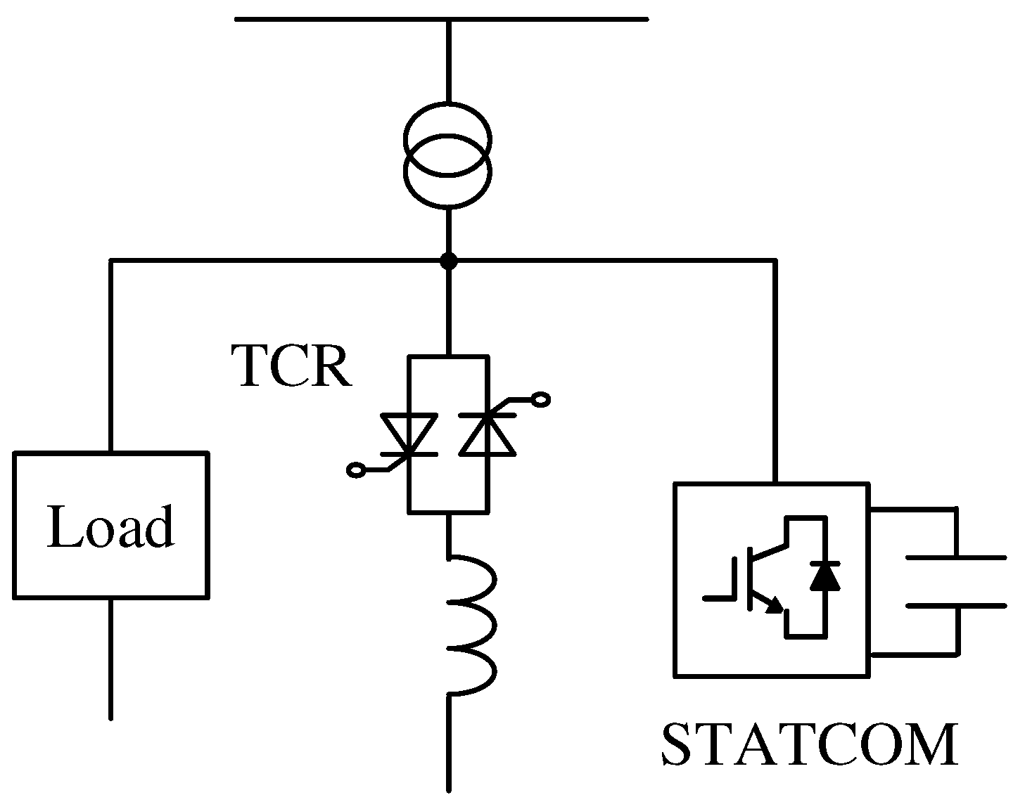
Figure 4.
Circuit diagram of the proposed hybrid static VAR compensator (SVC) with a series active filter (AF).
Figure 4.
Circuit diagram of the proposed hybrid static VAR compensator (SVC) with a series active filter (AF).

Figure 5.
Per-phase equivalent circuits for Figure 4 with the control gain . (a) Per-phase equivalent circuit. (b) Per-phase equivalent circuit for current-source harmonic-producing load. (c) Equivalent circuit for . (d) Equivalent circuit for .
Figure 5.
Per-phase equivalent circuits for Figure 4 with the control gain . (a) Per-phase equivalent circuit. (b) Per-phase equivalent circuit for current-source harmonic-producing load. (c) Equivalent circuit for . (d) Equivalent circuit for .

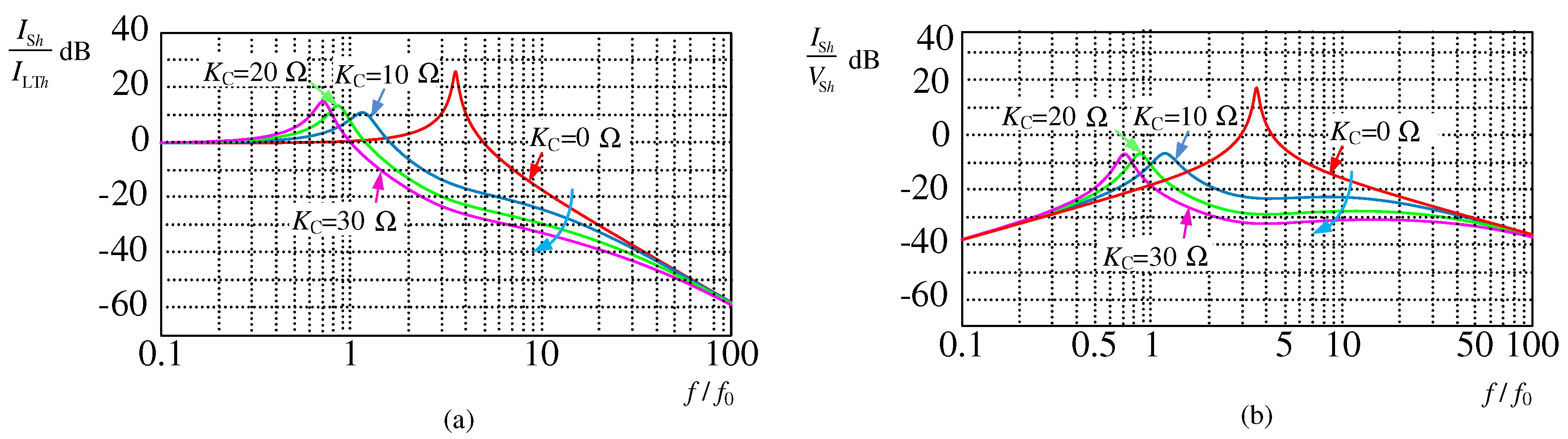
Figure 7.
Simulation waveforms for Figure 4 before/after the series active filter (AF) with of 10 was started.
Figure 7.
Simulation waveforms for Figure 4 before/after the series active filter (AF) with of 10 was started.
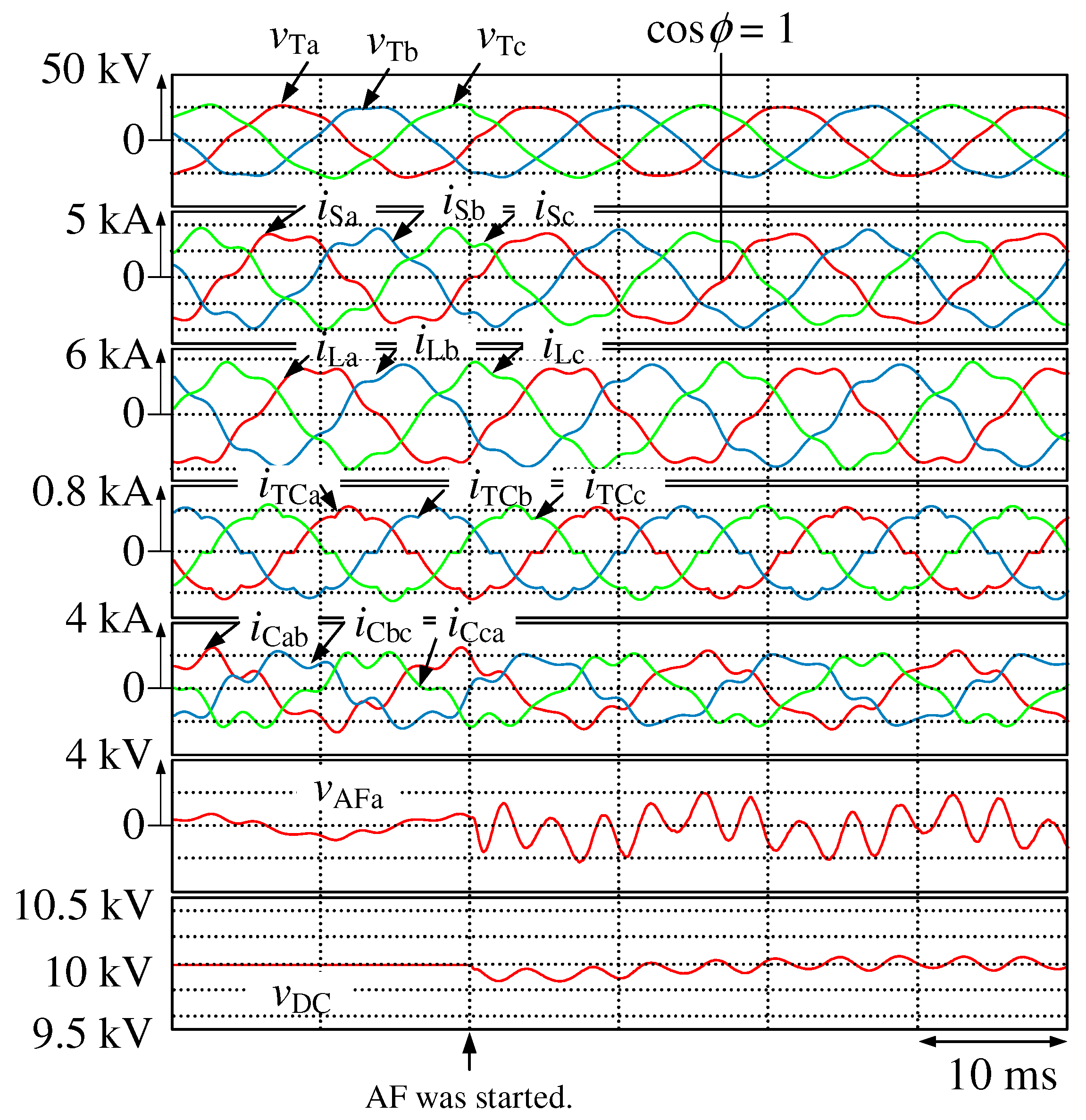
Figure 8.
Simulation waveforms for Figure 4 before/after the series active filter (AF) with of 20 was started.
Figure 8.
Simulation waveforms for Figure 4 before/after the series active filter (AF) with of 20 was started.

Figure 9.
Simulation waveforms for Figure 4 before/after the series active filter (AF) with of 30 was started.
Figure 9.
Simulation waveforms for Figure 4 before/after the series active filter (AF) with of 30 was started.

Figure 10.
Spectra of a-phase source current .
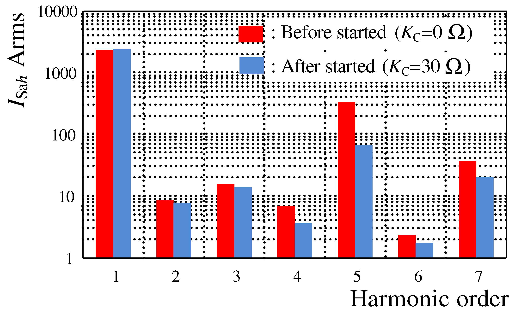
Figure 11.
Simulation waveforms for Figure 4 with the three-phase load variation from 0.6 to 1 pu, when the control gain was 30 .
Figure 11.
Simulation waveforms for Figure 4 with the three-phase load variation from 0.6 to 1 pu, when the control gain was 30 .

Table 1.
Previously proposed hybrid static VAR compensator (SVC) topologies and functions of added active filter (AF).
Table 1.
Previously proposed hybrid static VAR compensator (SVC) topologies and functions of added active filter (AF).
| Topology | Functions of Added AF | Required Rating of Added AF for Three-Phase Load Rating | |
|---|---|---|---|
| Figure 1 | Thyristor-controlled reactor (TCR) and passive LC filter with series AF | Improvement of harmonic voltage compensation characteristics of passive LC filter | 1.4% |
| Figure 2 | TCR and phase-leading capacitor (PLC) with series AF | Harmonic current compensation | 4.0% |
| Figure 3 | TCR and parallel-connected static synchronous compensator (STATCOM) | Fundamental reactive-power control and harmonic current compensation | 80% |
Table 2.
Circuit Constants for Figure 4.
Table 2.
Circuit Constants for Figure 4.
| Item | Symbol | Value |
|---|---|---|
| Source inductor | 1.64 mH | |
| Filter inductor | 0.066 mH | |
| Filter capacitor | 96 μF | |
| Inductors of SVC | , , | 108 mH |
| PLCs | , , | 114 μF |
| DC capacitor | 4700 μF | |
| DC-capacitor voltage | 10 kVdc | |
| Switching frequency | 12 kHz | |
| Cut-off frequency of second-order LPF | 179 Hz | |
| Damping factor of second-order LPF | 0.7 | |
| Proportional gain for constant DC-capacitor | 0.6 | |
| voltage controller | ||
| Integral gain for constant DC-capacitor | 0.01 | |
| voltage controller | ||
| Proportional gain for PLL | 5 | |
| Integral gain for PLL | 0.01 | |
| Control gain for series AF | 10, 20, 30 |
Table 3.
Data for the matching transformers (MTs) used in Figure 4.
Table 3.
Data for the matching transformers (MTs) used in Figure 4.
| Primary-side voltage | 1.19 kVrms |
| Primary-side rated current | 1.42 kArms |
| Turn ratio | 1:2 |
| No load current | 56.8 Arms (4.0%) |
| Iron loss | 17 kW |
| Copper loss | 34 kW |
| Impedance voltage | 35.6 Vrms (3.0%) |
© 2017 by the authors. Licensee MDPI, Basel, Switzerland. This article is an open access article distributed under the terms and conditions of the Creative Commons Attribution (CC BY) license (http://creativecommons.org/licenses/by/4.0/).
Share and Cite
MDPI and ACS Style
Tokiwa, A.; Yamada, H.; Tanaka, T.; Watanabe, M.; Shirai, M.; Teranishi, Y. New Hybrid Static VAR Compensator with Series Active Filter. Energies 2017, 10, 1617. https://doi.org/10.3390/en10101617
AMA Style
Tokiwa A, Yamada H, Tanaka T, Watanabe M, Shirai M, Teranishi Y. New Hybrid Static VAR Compensator with Series Active Filter. Energies. 2017; 10(10):1617. https://doi.org/10.3390/en10101617
Chicago/Turabian StyleTokiwa, Ayumu, Hiroaki Yamada, Toshihiko Tanaka, Makoto Watanabe, Masanao Shirai, and Yuji Teranishi. 2017. "New Hybrid Static VAR Compensator with Series Active Filter" Energies 10, no. 10: 1617. https://doi.org/10.3390/en10101617
Note that from the first issue of 2016, this journal uses article numbers instead of page numbers. See further details here.