Review

SU-8 Cantilevers for Bio/chemical Sensing; Fabrication, Characterisation and Development of Novel Read-out Methods

by
Maria Nordström
1,*,
Stephan Keller
1,
Michael Lillemose
1,
Alicia Johansson
2,
Søren Dohn
1,
Daniel Haefliger
3,
Gabriela Blagoi
1,
Mogens Havsteen-Jakobsen
1 and
Anja Boisen
1
1
MIC – Department of Micro and Nanotechnology, Technical University of Denmark, DTU building 345 East, DK-2800 Kongens Lyngby, Denmark
2
Now at PhotoSolar ApS, Denmark
3
Now at HARTING Mitronics AG, Switzerland
*
Author to whom correspondence should be addressed.
Sensors 2008, 8(3), 1595-1612; https://doi.org/10.3390/s8031595
Submission received: 2 November 2007 / Accepted: 3 March 2008 / Published: 10 March 2008

Abstract

:
Here, we present the activities within our research group over the last five years with cantilevers fabricated in the polymer SU-8. We believe that SU-8 is an interesting polymer for fabrication of cantilevers for bio/chemical sensing due to its simple processing and low Young's modulus. We show examples of different integrated read-out methods and their characterisation. We also show that SU-8 cantilevers have a reduced sensitivity to changes in the environmental temperature and pH of the buffer solution. Moreover, we show that the SU-8 cantilever surface can be functionalised directly with receptor molecules for analyte detection, thereby avoiding gold-thiol chemistry.

1. Introduction

Cantilever-based sensing is a growing research field within micro technology with research groups found around the world [1-10]. The technology offers a method for rapid, label-free, on-line and in-situ detection of specific bio/chemical analytes by detecting the nanomechanical response of a cantilever sensor. Cantilever sensors can be operated either in dynamic mode or static mode.
In the dynamic mode the resonance frequency, f0, of the cantilever is monitored and as masses adsorb onto the structure, the resonance frequency decreases. This change in resonance frequency, Δfres, for a homogeneously distributed adsorbed mass is given by, equation (1).
Δ f res f 0 Δ m 2 m 0
where Δm is the mass of the adsorbents and m0 is the initial mass of the cantilever.
Most measurements of bio/chemical reactions are performed in liquid, where dynamic mode operation is difficult due to viscous damping. Therefore, this manuscript is focused on static mode operation of the cantilever based sensors only.
In the static mode it is the surface stress generated when molecules selectively adsorb onto one surface of the cantilever that is measured. The generated surface stress results in a bending of the cantilever, typically in the order of a few 100 nm's. Figure 1 shows this principle schematically. The degree of cantilever bending can be related to the amount of analyte present [11].
The deflection, Δz, of a cantilever with a length-to-width ratio much larger than one operated in static mode is described by equation (2).
Δ z = 3 Δ σ ( 1 ν ) l 2 E t 2
where Δσ is the differential surface stress, ν is the Poisson's ratio and E is the Young's modulus of the cantilever material respectively and l and t are the length and thickness of the cantilever respectively.
There are several methods to detect the cantilever bending, where the most commonly used principle is the beam deflection method known from atomic force microscopy [12] and integrated piezo-resistive read-out [13, 14].
In this manuscript, we present the research results for cantilever based sensors fabricated in the polymeric material SU-8 developed in our research group over the last five years. It aims at giving a comprehensive summary where the detailed analysis is left to the referred material. In the first part of the paper, the material properties of the polymer SU-8 and the cantilever fabrication are presented. Studies have also been performed to characterise the chemical structure of the SU-8 surface for further selective functionalisation of the SU-8 devices. In the second part of the manuscript, three different types of integrated read-out principles for the cantilever sensors are described; an optical read-out, a piezo-resistive read-out and an autonomous read-out. Finally, an outlook and discussion about future challenges and developments for the cantilever sensors are given.

2. SU-8 as device material
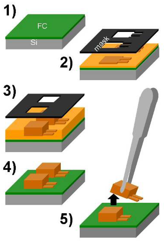
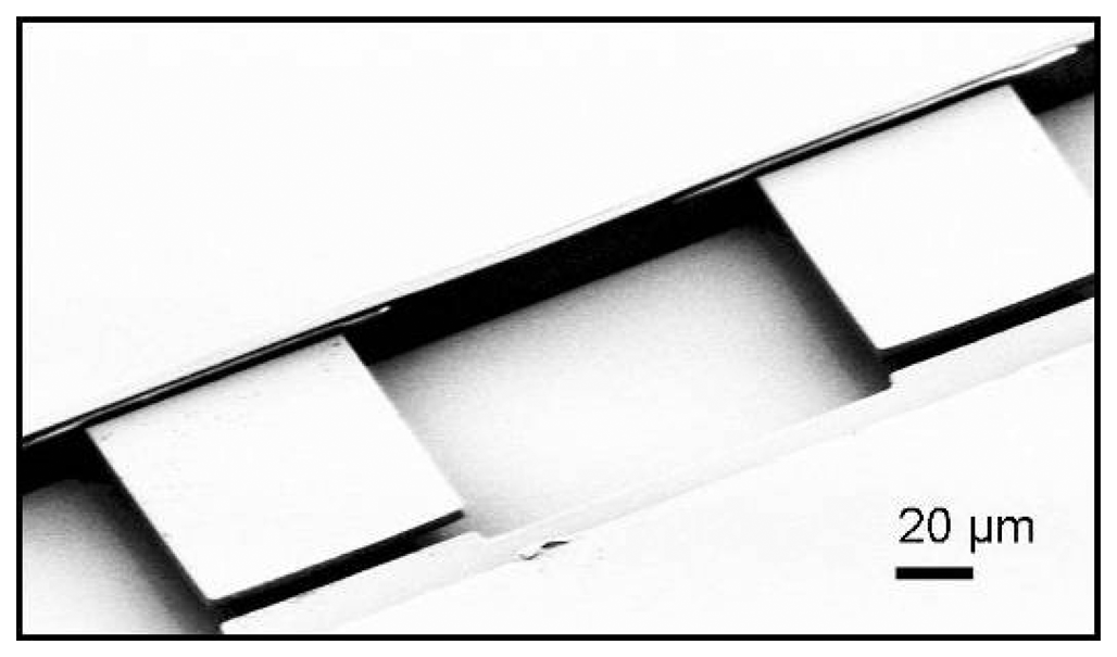
SU-8 is a negative epoxy-based photo-resist developed by IBM for the micro technology industry in the early 1990's [15]. It is a polymer that can be spin-coated to thicknesses ranging from below 1 μm up to 1 mm and the final structures can be defined by UV lithography or e.g. e-beam lithography [16]. The low Young's modulus and high mechanical strength of SU-8 makes it a highly suitable material for fabrication of cantilever-based sensors, as the low Young's modulus ensures an increased detection sensitivity as seen in equation (2) above.

2.1. Fabrication

The SU-8 cantilevers developed in our group are fabricated with UV lithography. For the SU-8 cantilevers with no integrated read-out the following five-step-procedure is applied, as depicted in figure 2:
  • An advanced silicon etch device is used to deposit a fluorocarbon coating which serves as release layer at the end.
  • A first step of photo-lithography with SU-8 2002 or SU-8 2005 (MicroChem, USA) allows for the definition of the cantilever layer. The cantilever thickness is determined by the speed and acceleration of the spin-coater as well as the viscosity of the SU-8.
  • A 200-μm-thick film of SU-8 2075 is spin-coated and patterned to form the support body of the cantilever chip.
  • The non-exposed SU-8 is developed in propyleneglycolmethyletheracetate (PGMEA)
  • The chips are mechanically released from the substrate by the use of tweezers.
It is also possible to pattern an Au layer on the cantilevers after step 3 if that is required by the immobilisation protocol used for the receptor molecules. The cantilever array in figure 3 does not have this Au layer.
The development of a new dry release method was crucial for the cantilever fabrication [17]. Previously, a wet release (e.g. etching of a sacrificial Cr layer) has been applied. Such a release is not only cumbersome but it is often seen that the cantilevers stick to the thick SU-8 support body due to the capillary forces as the cantilevers are taken out of the etchant after rinsing [18]. In a thorough experimental investigation, we have optimised the surface properties of a plasma-polymerised fluorocarbon coating to allow for the structuring and following release of thin SU-8 cantilevers with a high yield [19]. The processing of the thin SU-8 film has been optimised in a series of experiments where the film stress, cross-linking density and lithographic resolution as a function of the process-parameters are investigated. We have successfully fabricated polymer chips with cantilever arrays of 2-μm-thickness, width of 75 μm and a length of 200 μm, shown in figure 3. The released devices show excellent mechanical stability and initial end-point deflections of only a few micrometers.

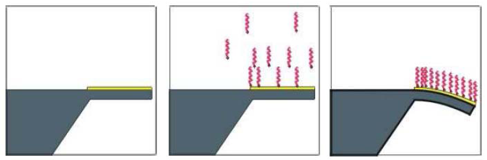
2.2. SU-8 surface functionalisation

To functionalise cantilevers with receptor molecules the cantilevers are often coated with Au so that thiol molecules can bind to the surface. However, it is beneficial to move away from the classical immobilisation procedure of thiol-Au because the thiol-Au chemistry is irreversible and the grafting density is highly dependent on surface cleanliness [20]. Furthermore, the stiffness of the cantilever is reduced and the temperature stability is improved by avoiding an Au coating on the cantilever surface. For a bi-layered cantilever the bimorph effect is an issue with respect to temperature fluctuations [21].
SU-8 cross-links via photon-initiated ring opening of the epoxy groups of the monomers [22]. It is therefore likely that the surface of the final SU-8 structures have non-reacted epoxy groups present. We have shown that the contact angle of SU-8 can be reduced from its initial value of 90° (hydrophobic) down to 25° (hydrophilic) by treating the surface with the Cr etchant cerric ammonium nitrate (CAN) and ethanolamine [23]. CAN is a catalyst for epoxy ring opening [24] so it is assumed that there are indeed free epoxy groups on the SU-8 surface which after reaction with CAN react with the ethanolamine.
Using fluorescence, we have also shown that single stranded DNA (ssDNA) can be adsorbed onto a cured SU-8 surface with probe densities of about 100 fmol/mm2 [25]. The probes appear to be covalently attached to the SU-8 because the functionality of the probes is not reduced by incubation for 10 minutes in water at 98 °C. It is unclear which type of chemical bond provides the link between the DNA and the SU-8 surface, but again it is speculated that the non-reacted epoxy-groups on the SU-8 surface are involved. It is likely that these groups react with the amine groups of the DNA strands.
Furthermore, a thorough study on the direct immobilisation of proteins onto SU-8 surfaces has been performed [26]. Sandwich immunoassays proved that IgG type proteins performed best when they were immobilised on bare SU-8 which had a well characterised surface consisting of epoxy groups. Transformation of the SU-8 surface into amino-modified (amino-silanisation) and hydrophilic surfaces (CAN pre-treatment) resulted in the degradation of the limit of detection of the C-reactive protein (CRP) immunoassays. These results also support the assumption that there are non-reacted epoxy groups on the SU-8 surface. The results show that bare SU-8 and CAN treated SU-8 can be directly functionalised with antibodies against CRP which can be used for sandwich immunoassays with clinical relevant limits of detection, such as 0.03 μg/ml and 0.08 μg/ml respectively. These values are similar to the sensitivities obtained with ELISA assays for CRP [27]

2.3 Experimental results

To verify the higher stress sensitivity of SU-8 cantilevers to conventional cantilevers, we have performed an experiment where we compare the bending of an Au-coated SU-8 cantilever and an Au-coated commercial Si3N4 cantilever (Olympus, Japan) when both cantilevers are subjected to the same thiolated DNA. The bending was detected optically. Both cantilevers are 20 μm wide and 200 μm long. The SU-8 cantilever has a thickness of 1.6 μm and the Si3N4 cantilever is only 500 nm thick. Following equation (2), the expected deflection at identical surface stress is a factor of ten larger for the SU-8 cantilever than for the Si3N4 cantilever even though the first cantilever has a thickness of more than three times the latter. The Young's modulus of the two different cantilevers materials are 2-3 GPa [28] for the SU-8 and 190 GPa [29] for the Si3N4. Our results show that the SU-8 cantilever bends six times more compared to the Si3N4 cantilever when they are placed in a microfluidic cell and subjected to an injection of the same concentration and amount of thiolated DNA, figure 4. The small discrepancy between the theory and the measurements are most likely due to the 20 nm thin Au layer on top of the cantilevers used for the immobilisation of the probe DNA [30].
In figure 5(a) the thermal drift and cantilever deflections due to pH variations are compared for a fluorocarbon-coated SU-8 cantilever and an Au-coated Si3N4 cantilever. The bending of the cantilevers is read out by the optical lever principle. For this experiment the SU-8 cantilever is not coated with a layer of Au since it is not necessary for obtaining an immobilised layer of receptor molecules. In the previous experiment the SU-8 cantilever was coated with Au to ensure identical conditions for the applied chemistry. Here, the new fluorocarbon-based release method has an additional advantage; it provides a thin fluorocarbon passivation layer on one of the cantilever surfaces after release and thereby ensuring the receptor molecules only are immobilised onto the SU-8 surface [19]. It is seen that the Si3N4 cantilever is more sensitive to temperature and pH fluctuations than the SU-8 cantilever. This is the expected result since the material properties of Si3N4 and Au are very different whereas SU-8 and the fluorocarbon-coating are more similar. This means that the drift due to temperature fluctuations or pH changes is significantly reduced for the SU-8 cantilevers [31].

3. Read-out principles

The most straight forward method to detect the deflections of cantilevers is to use an external optical read-out system consisting of a laser diode and a position-sensitive photo-detector. To move our research towards real life devices we have also developed two integrated read-out modes for SU-8 cantilevers; an optical read-out scheme where the cantilever also acts as a waveguide [32] and a piezo-resistive read-out using Au strain gauges [33]. Moreover, proof-of-concept of an autonomous read-out method has been presented [34].

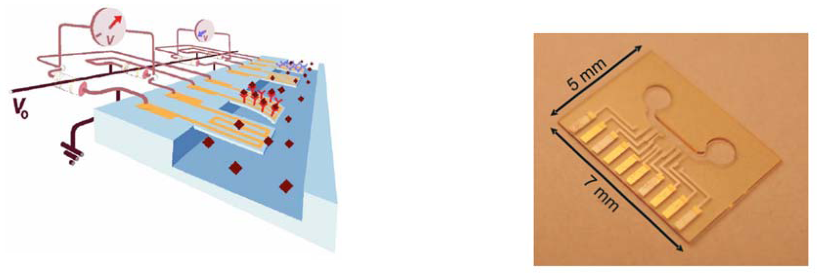
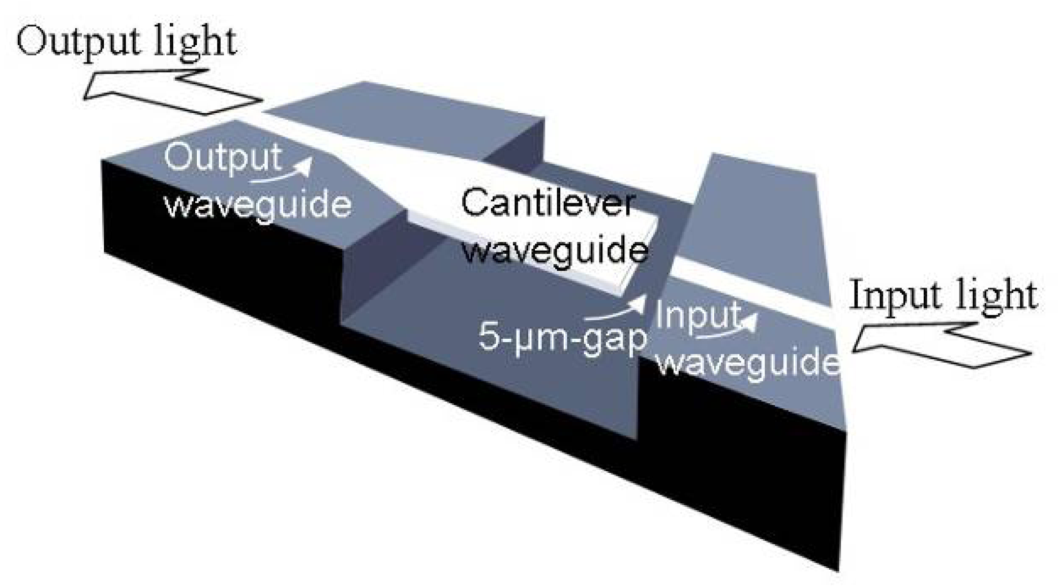
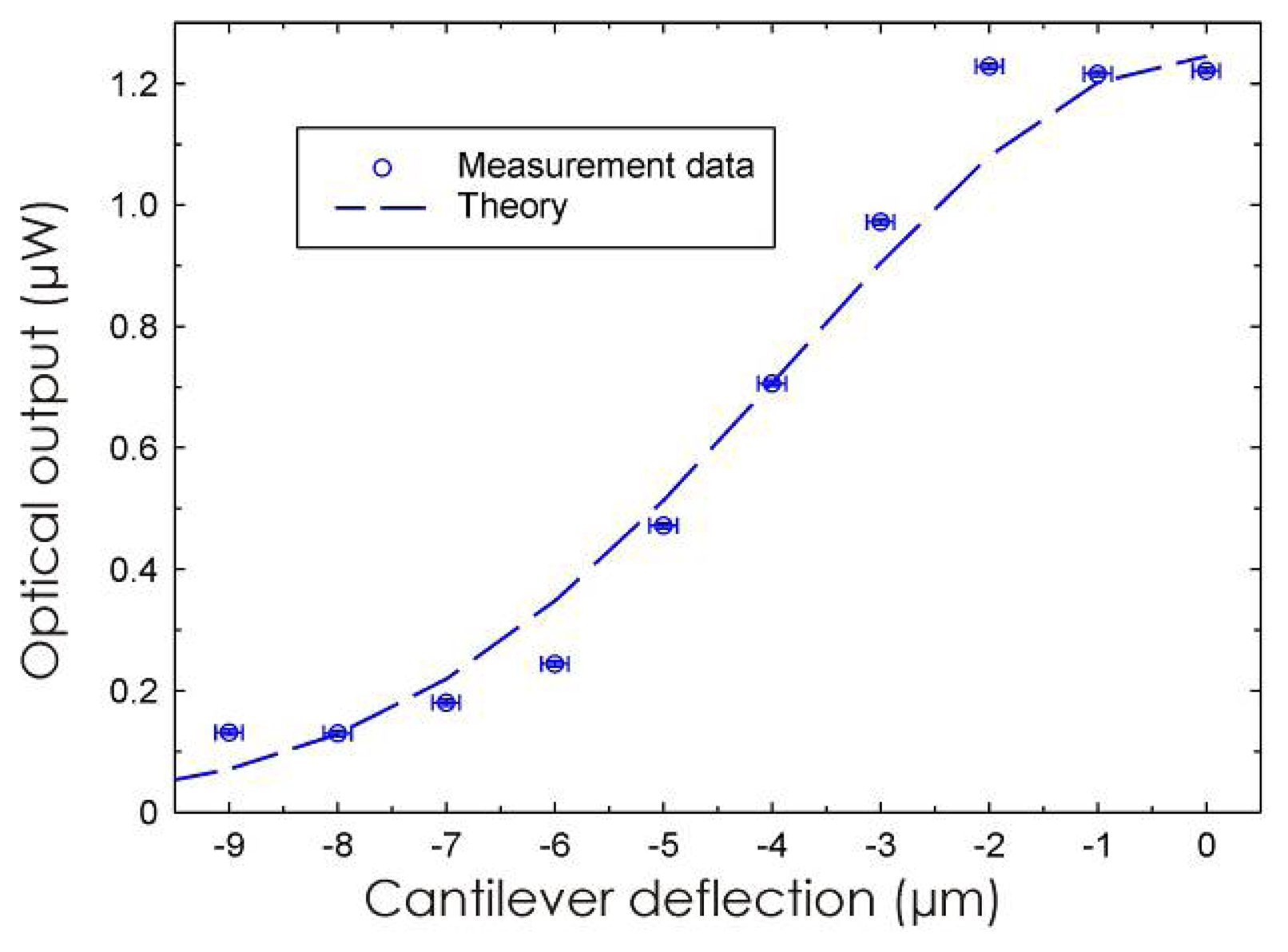
3.1 Integrated optical read-out

The system with the integrated optical read-out is an all-polymer device. The cantilever and waveguide core are structured in SU-8 2005 (MicroChem, USA), which has been reported in the literature to have a low propagation loss combined with providing high cantilever sensitivity [35, 36, 31]. For cladding material the modified SU-8, mr-L 6050 XP (MicroResist, Germany) is used. The cladding has a thickness of 22 μm and the waveguide core is 10 μm wide and 4.5 μm thick. This material combination has been shown to be highly suitable for the fabrication of MOEMS (micro-opto-electromechanical-system) devices [37]. The chips are fabricated by a wafer-bonding process inspired by Ruano et al. that is published elsewhere [38]. Figure 6 shows an SEM image of the final fabricated chip with two cantilevers. The width of the cantilevers is 75 μm and the length is 100 μm with a thickness of 4.5 μm. It is clearly seen that the cantilevers are aligned with the output waveguides on the opposite side of the microfluidic channel.
The wavelength of operation of this system is 1310 nm and the light is butt-coupled into and out of the system via single-mode fibers with a core diameter of 9 μm (Corning, USA). After entering the system, the light is guided via the 10-μm-wide input waveguide towards a region where the free-hanging cantilever is situated, figure 7. The input waveguide and the cantilever are in the same plane and when the light exits the input waveguide it travels across a 5-μm-wide gap towards the cantilever. The light is coupled into the cantilever and continues, via the 10-μm-wide output waveguide to the photo-detector. As the cantilever bends, the amount of light coupled into the cantilever waveguide is reduced and the intensity of the output light decreases.
The read-out method is characterised by mechanically deflecting the cantilever a known distance while monitoring the optical output intensity. A 1310 nm single mode laser source (HP 81552SM, Hewlett Packard, USA) is used as input and the intensity is detected by a lightwave multimeter (HP 81532A, Hewlett Packard, USA). The cantilever is deflected by pressing onto the apex with a tungsten probe mounted in a custom-made set-up where the vertical displacement is controlled with sub-micron resolution. There is a drift in the system of -0.2 nW/s due to a small drift of the micrometer screw and the photo-detector has a noise level of ± 0.5 nW. Figure 8 shows a comparison between the theoretically calculated read-out signal and the experimentally obtained data points when operating the system in air.
In the most sensitive region, at a cantilever deflection of 3-5 μm, the calculated minimum detectable cantilever tip deflection is found to be 45 nm, which corresponds to an approximate surface stress resolution of 0.2 N/m using Stoney's equation. The value is found by considering a noise level of +/- 5 nW. For comparison a typical DNA hybridisation results in a surface stress of only 4 mN/m [11, 39] so there are still improvements required before satisfying sensitivity is reached.

3.2 Piezo-resistive read-out

Another read-out principle developed is an integrated piezo-resistive read-out using Au strain gauges. The SU-8 chip has four micrometer-sized cantilevers situated in a channel structure, figure 9(a).
The chips are fabricated in SU-8 2002 and 2075 (MicroChem Corp., USA) on a Si wafer and are released after fabrication. The cantilevers are 280 μm wide, 215 μm long and about 3.5 μm thick. The thickness of the Au used for the piezo-resistors is 60 nm and the resistance of the meander structured piezoresistors is approximately 500 Ω. The SU-8 chip is mounted on a printed circuit board and the electrical interconnection is achieved either by flip-chip bonding or by silver paste [40]. A bending of the cantilever results in a resistance change, ΔR, in the integrated piezo-resistors due to the dimensional changes of the Au strain gauges. To minimise the noise and drift of the output signal, the resistors are connected in a Wheatstone bridge configuration and a reference cantilever is used for all measurements. The change in surface stress, Δσ, can be expressed by equation (3).
Δ σ = A Δ V out V i n
where ΔVout is the output voltage change from the Wheatstone bridge, Vin is the input voltage and A is a constant which depends on the surface stress sensitivity of the cantilever. For a 3.5 μm thin SU-8 cantilever with a 20 nm thin Au coating, A=104 N/m.
The surface stress sensitivity of these cantilevers in liquid is characterised by chemisorption of mercaptohexanol (MCH) on an Au-coated cantilever. The measuring cantilever is covered with an evaporated Ti/Au layer with a thickness of 2/20 nm while the reference cantilever is left uncoated. This configuration is not ideal to cancel out drifts due to temperature variations or changes in pH but when relatively large signals are expected (such as for MCH immobilisation) the asymmetric configuration does not have a large influence. [41]. Before the chips are used, they are cleaned in a commercial UV/ozone system (PR 100, UVP Inc.) for 30 min to remove contamination. MCH is dissolved in MilliQ and injected into the chamber at a pump rate of 10 μl/min. As seen in the figure 10 below, the resulting surface stress increases from 0.06 to 0.16 N/m when the thiol concentration increases from 0.2 to 0.5 mM. For a concentration of 1 mM, the surface stress change is about 0.24 N/m. The results are comparable to previously reported surface stress measurements using alkanethiols [42]. As a control, hexanol (C6H13-OH) without a thiol group is also injected into the microfluidic system. As expected, no significant cantilever response is observed for the control experiment.
Preliminary CRP measurements using the SU-8 cantilevers have been performed to validate a real application of these devices [43]. Here, SU-8 cantilevers with integrated gold piezoresistors were used for detection of the interaction between CRP and anti-CRP antibody. The capture antibody was adsorbed on the surface of the cantilever for two hours and the reference cantilever was blocked with 1% bovine serum albumin (BSA) and skimmed milk. The concentration of the injected CRP solution was 10 μg/ml and the reaction proved to yield a surface stress change of about 13 mN/m.
The measured sensitivity of the SU-8 cantilever is about the same as for Si-based cantilevers with integrated read-out previously fabricated in the group [44]. This is because reduced surface stress sensitivity due to the much lower gauge factor of Au compared to doped Si is compensated by the higher flexibility of the polymer cantilever. Moreover, the electrical noise level is much lower in Au than in Si.
As a further step to improve the sensitivity of the SU-8 cantilevers with integrated piezo-resistive read-out, we are investigating new materials applicable as strain gauges. The requirements for such a substitute material is that the gauge factor should be higher than that of Au (KAu = 2) and that it should be compatible with the process steps for the fabrication of SU-8 cantilevers (i.e. UV lithography). The use of a conducting polymer has several advantages; (i) the adhesion issue with polymer/metal are avoided (ii) the stiffness of the cantilever can be reduced due to the lower Young's modulus of the conducting polymer compared to Au and (iii) the drift experienced during cantilever measurements due to the bimorph effect is considerably reduced.
The first approach by our research group was to develop conducting SU-8 in the form of a carbon-black/SU-8 composite [45]. Percolation theory describes the conductivity of polymer composite materials based on a conducting network of randomly dispersed conducting particles in an insulating polymer matrix, see figure 11. At a critical particle loading, the conductivity of the composite material will change drastically due to the interruption of the conductive pathways. From the initial investigations, using a simple standard two-point-probe method, it was found that the percolations threshold for this composite is at 12% carbon content.
The composite samples are prepared by addition of carbon nanoparticles to the SU-8 followed by ultrasonic mixing. 7 μm thick cantilevers with a 4 μm thick layer of encapsulated composite piezo-resistor were fabricated. The force sensitivity of the cantilever sensors fabricated by this process was determined by deflecting the cantilever with a tungsten probe controlled by a micrometer screw in steps of 5 μm. The experiments reveal that the composite has a gauge factor between 15-20.
There were several issues experienced when working with the carbon/SU-8 composite. Inhomogeneous dispersion of the carbon particles lead to a high error margin of at least 15 % and it is difficult to obtain well defined structures at higher carbon loading. Therefore, other conducting polymers have also been investigated. For example, we have reported on the experimentally observed piezo-resistive effect in strained poly 3,4-ethylenedioxythiophene (PEDT) [46]. The measurements are made on test chips with PEDT resistors defined by conventional UV lithography. To investigate the properties of this material, the strain gauge PEDT resistors are patterned by conventional UV-lithography and subsequently subjected to a constant stress. The test samples are placed in a four point bending fixture which exerts the stress uniaxially [47]. The preliminary tests indicate that strained PEDT has a gauge factor of 3.41 ± 0.42 which gives evidence of potential for piezo-resistive read-out for SU-8 cantilevers.
A second intrinsically conducting polymer which we have investigated as a candidate for the strain gauges is polyaniline (Panipol Oy, Finland) [48]. Initially, attempts were made to mix Panipol T (>85% toluene and < 15% polyaniline salt) in SU-8 as previously experimented with for the carbon black particles. However, the mixture is very inhomogeneous and viscous and it is impossible to spin-coat the composite. We believe that due to the acidic nature of Panipol T, the cross-linking process of SU-8 is kick-started and UV-structuring is therefore not possible. Instead, the polyaniline test samples are defined with plasma ashing (O2 and N2 plasma) using SU-8 as an etch mask.
The prepared test samples are characterised in a four point bending fixture where the chips are subjected to a pure bending moment resulting in a uniform stress being applied to the polyaniline thin film [48]. Simultaneously, the two-point resistance of the polyaniline thin film is measured in a series where cycles of tensile stress of 160 MPa are applied to the polyaniline thin film. Two complete cycles are made and figure 12 shows the measured resistance, R, as a function of time. The coloured areas represent periods where the tensile stress is applied. The resistance of the polyaniline thin film decreases when the tensile stress is applied. By using Hooke's law and the relation, ΔR/R=Kε, where ε is the strain, we can calculate the gauge factor, K, for the polyaniline film. We find K1= -4.9 and K2= -4.1 for the 1st and 2nd cycle, respectively, hence polyaniline has a negative gauge factor. The resistivity was found to be ρ=1.2−1.3×10⁻³ Ωm.

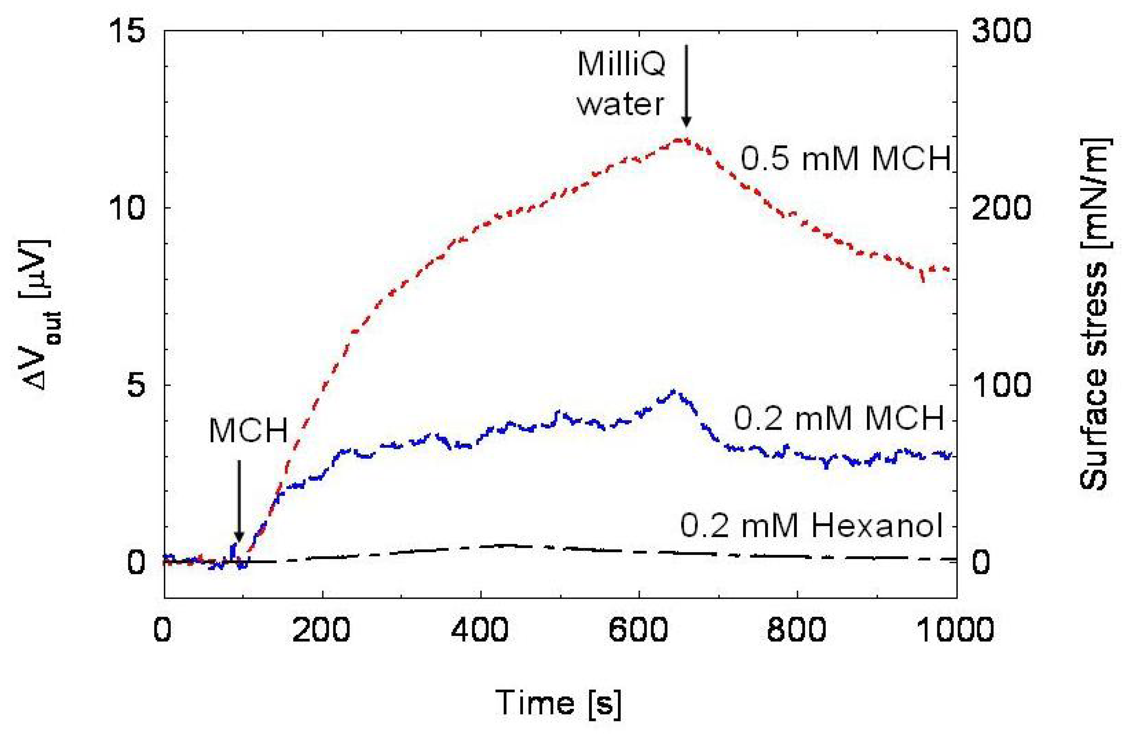
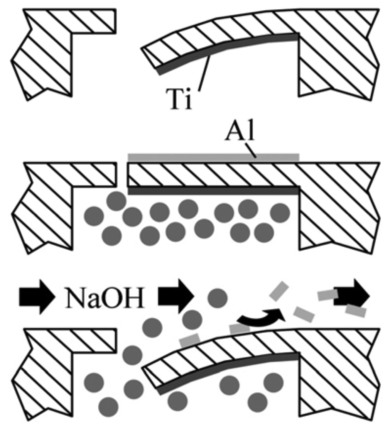
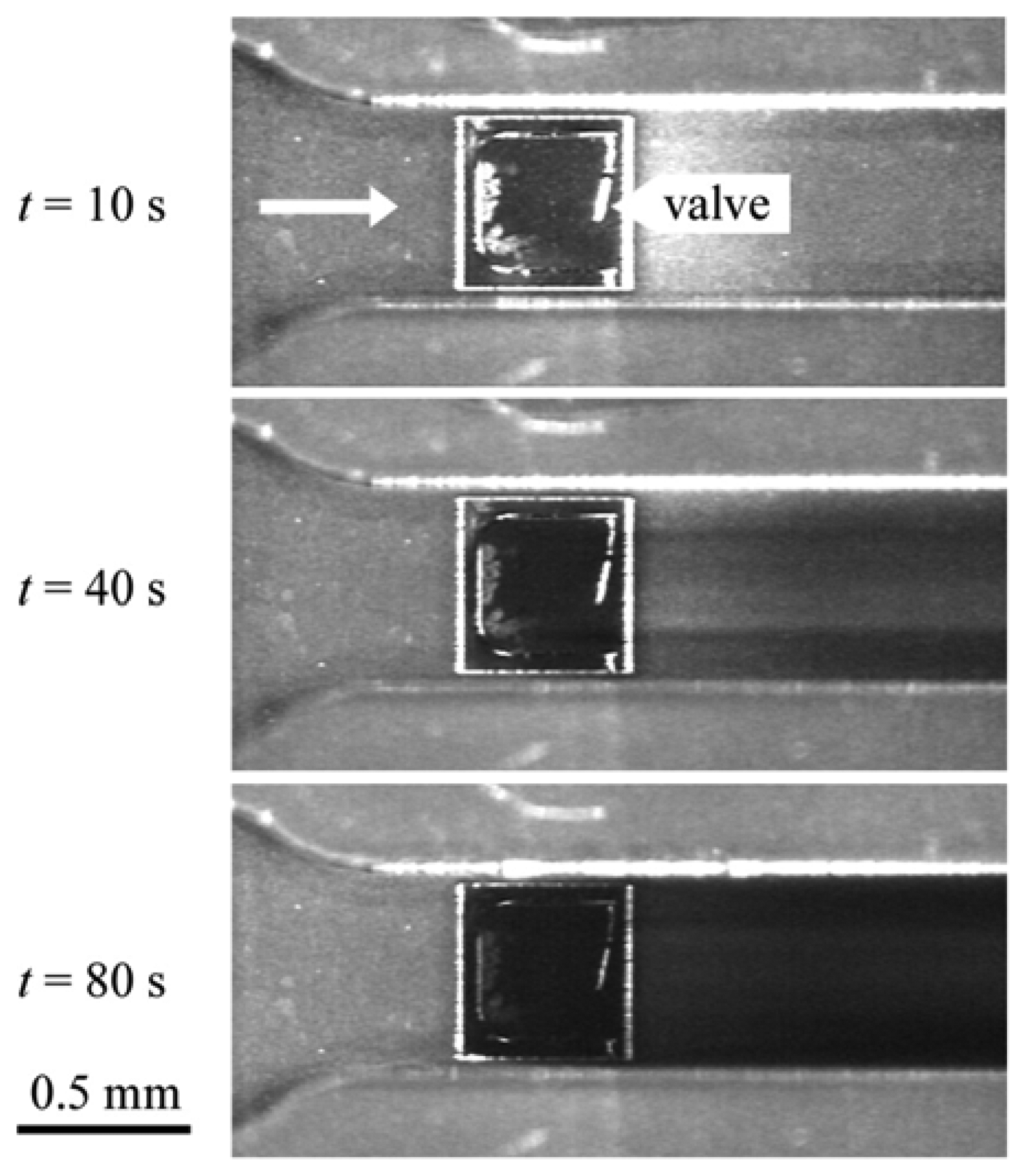
3.3 Autonomous read-out

The third integrated read-out method developed is a self-actuated micro valve, fabricated completely in SU-8 [49]. The valve consists of a suspended square flapper that separates two microfluidic systems. Upon introduction of the analyte in the first microfluidic channel, a surface stress change is generated on the flapper and it bends. The opening of the valve releases the marker solution in the second microfluidic system which allows for a visual read-out. Figure 13 shows a schematic drawing of the operating principle using a model system with two metal layers to show proof-of-concept. The Ti layer on the lower side of the flapper is used to compensate the tensile stress in the Al film and ensure the flapper is closed [50].
By using coloured ink as the marker solution this chip can be used as an autonomous read-out system for a diagnostic array. Each valve can be functionalised with a different receptor enabling parallel screening of multiple substances. By optically detecting the colour change in the microfluidic system downstream of the valve array, the presence of the ink in one channel identifies a certain chemical process, which occurs on the respective valve.
The chip is fabricated following the process sequence described in section 2.1. The completed valve array chip is mounted on a test rig where the inlet and outlet feeds for the microfluidic network in the SU-8 chip is fabricated in a 10-mm-thick polymethyl methacrylate (PMMA) support by mechanical drilling. The feeds are equipped with threads to connect the system via polytetrafluoroethylene (PTFE) tubing to a pump and reservoirs for metal etchant and water. The top of the valve array is covered by a glass lid with a thin layer of flexible polydimethylsiloxane (PDMS) for sealing. The individual parts are clamped together by an Al lid screwed onto an Al base part. The reservoir below the valve array is filled with green nutrition colour. The microfluidic network in the SU-8 above the valves is first filled with water by a syringe pump and rinsed for 5 min. Subsequently, a solution of 0.5 M NaOH is introduced. Figure 14 shows the effective release of the green marker solution upon contact of the valve surface covered with a 400 nm Al layer with the NaOH solution.

4. Conclusion and Outlook

In this review article we have presented the developments of SU-8 based cantilevers within our research group. We show three types of integrated read-out principles; optical, piezo-resistive and autonomous. We also show results using conventional external optical read-out where these SU-8 cantilevers are compared to Si3N4 cantilevers. It is clearly seen from this work that the SU-8 cantilevers present several advantages such as increased surface stress sensitivity, reduced drifts and reduced fabrication time. Furthermore, we show that it is possible to pattern receptor molecules directly on the SU-8 surface. Thereby, drifts can be further reduced since the use of an Au layer for molecular immobilisation can be avoided.
One of the key challenges faced today for the advancements of these polymeric sensors is to achieve a reproducible manufacturing process. The work here shows that we can obtain successful fabrication of 2-μm-thin SU-8 cantilevers with negligible initial end-point deflection. However, it is absolutely necessary to have identical cantilevers with the same dimensions and mechanical properties (e.g. stiffness and intrinsic stress) not only in one array but also between different chips and batches. We also need to perform further investigations into the long-term stability of these cantilevers.
We believe that SU-8 is an interesting polymer for cantilever sensors but naturally there could be additional polymers to investigate, something which we might move towards in the future. It will also be an aim for us to develop further novel read-out methods for the cantilever sensors to enable true miniaturisation and the realisation of point-of-care devices.

Acknowledgments

The research presented above has only been made possible by the funding from the following sources; the Danish Research Council (the FTP), the Technical University of Denmark and the Swiss National Science Foundation, which is acknowledged by the authors.

References and Notes

  1. Álvarez, M.; Carrascosa, L.G.; Moreno, M.; Calle, A.; Zaballos, Á.; Lechuga, L.M.; Martínez-A, C.; Tamayo, J. Nanomechanics of the formation of DNA self-assembled monolayers and hybridization on microcantilevers. Langmuir 2004, 20, 9663–9668. [Google Scholar]
  2. Backmann, N.; Zahnd, C.; Huber, F.; Bietsch, A.; Plückthun, A.; Lang, H.-P.; Güntherodt, H.-J.; Hegner, M.; Gerber, Ch. A label-free immunosensor array using single-chain antibody fragments. Proceedings of National Academy of Science US 2005, 102, 14587–14592. [Google Scholar]
  3. McKendry, R.; Zhang, J.; Arntz, Y.; Strunz, T.; Hegner, M.; Lang, H.-P.; Baller, M.K.; Certa, U.; Meyer, E.; Güntherodt, H.-J.; Gerber, Ch. Multiple label-free biodetection and quantitative DNA-binding assays on a nanomechanical cantilever array. Proceedings of National Academy of Science US 2002, 99, 9783–9788. [Google Scholar]
  4. Tabard-Cossa, V.; Godin, M.; Beaulieu, L.Y.; Grütter, P. A differential microcantilever-based system for measuring surface stress changes induced by electrochemical reactions. Sensors and Actuators B 2005, 107, 233–241. [Google Scholar]
  5. Desikan, R.; Armel, S.; Meyer, H.M.; Thundat, T. Effect of chain length on nanomechanics of alkanethiol self-assembly. Nanotechnology 2007, 18, 424028. [Google Scholar]
  6. Raiteri, R.; Butt, H.-J. Measuring electrochemically induced surface stress with an Atomic Force Microscope. Journal of Physical Chemistry 1995, 99, 15728–15732. [Google Scholar]
  7. Biswal, S.L.; Raorane, D.; Chaiken, A.; Birecki, H.; Majumdar, A. Nanomechanical detection of DNA melting on microcantilever surfaces. Analytical Chemistry 2006, 78, 7104–7109. [Google Scholar]
  8. Hyun, S.-J.; Kim, H.-S.; Kim, Y.-J.; Jung, H.-I. Mechanical detection of liposomes using piezoresistive cantilever. Sensors and Actuators B 2006, 117, 415–419. [Google Scholar]
  9. Lee, J.H.; Hwang, K.S.; Park, J.; Yoon, K.H.; Yoon, D.S.; Kim, T.S. Immunoassay of prostate-specific antigen (PSA) using resonant frequency shift of piexoelectric Nanomechanical microcantilever. Biosensors & Bioelectronics 2005, 20, 2157–2162. [Google Scholar]
  10. Joshi, M.; Kale, N.; Lal, R.; Rao, V.R.; Mukherji, S. A novel dry method for surface modification of SU-8 for immobilization of biomolecules in Bio-MEMS. Biosensors & Bioelectronics 2007, 22, 2429–2435. [Google Scholar]
  11. Fritz, J.; Baller, M.K.; Lang, H.P.; Rothuizen, H.; Vettiger, P.; Meyer, E.; Güntherodt, H.-J.; Gerber, Ch.; Gimzewski, J.K. Translating biomolecular recognition into nanomechanics. Science 2000, 288, 316–318. [Google Scholar]
  12. Meyer, G.; Amer, N.M. Novel optical approach to atomic force microscopy. Applied Physics Letters 1988, 53, 1045–1047. [Google Scholar]
  13. Boisen, A.; Thaysen, J.; Jensenius, H.; Hansen, O. Environmental sensors base don micromachined cantilever with integrated read-out. Ultramicroscopy 2000, 82, 11–16. [Google Scholar]
  14. Mukhopadhyay, R.; Lorentzen, M.; Kjems, J.; Besenbacher, F. Nanomechanical sensing of DNA sequences using piezoresistive cantilevers. Langmuir 2005, 21, 8400–8408. [Google Scholar]
  15. Lorenz, H.; Despont, M.; Fahrni, N.; LaBianca, N.; Renaud, P.; Vettiger, P. SU-8: a low-cost negative resist for MEMS. Journal of Micromechanics and Microengineering 1997, 7, 121–124. [Google Scholar]
  16. Gersborg-Hansen, M.; Thamdrup, L.H.; Mironov, A.; Kristensen, A. Combined electron beam and UV lithography in SU-8. Microelectronic Engineering 2007, 84, 1058–1061. [Google Scholar]
  17. Haefliger, D.; Nordström, M.; Rasmussen, P.A.; Boisen, A. Dry release of all-polymeric structures. Microelectronic Engineering 2005, 78-79, 88–92. [Google Scholar]
  18. Nordström, M. Fabrication of cantilever chip with complementary micro channel system in SU-8 for biochemical detection. MSc Thesis, Lund University & Technical University of Denmark, 2004. [Google Scholar]
  19. Keller, S.; Haefliger, D.; Boisen, A. Optimized plasma-deposited fluorocarbon coating for dry release and passivation of thin SU-8 cantilevers. Journal of Vacuum Science and Technology B. Accepted for publication.
  20. Bertilsson, L.; Liedberg, B. Infrared study of thiol monolayer assemblies on gold: preparation, characterization, and functionalisation of mixed monolayers. Langmuir 1993, 9, 141–149. [Google Scholar]
  21. Begley, M.R. The impact of materials selection and geometry on multi-functional bilayer micro-sensors and actuators. Journal of Micromechanics and Microengineering 2005, 15, 2379–2388. [Google Scholar]
  22. www.microchem.com
  23. Nordström, M.; Marie, R.; Calleja, M.; Boisen, A. Rendering SU-8 hydrophilic to facilitate use in micro channel fabrication. Journal of Micromechanics and Microengineering 2004, 14, 1614–1617. [Google Scholar]
  24. Iranpoor, N.; Salehi, P. Ceric ammonium nitrate: a mild and efficient reagent for conversion of epoxides to Beta-nitrato alcohols. Tetrahedron 1995, 51, 909–912. [Google Scholar]
  25. Marie, R.; Schmid, S.; Johansson, A.; Ejsing, L.; Nordström, M.; Haefliger, D.; Christensen, C.B.V.; Boisen, A.; Dufva, M. Immobilisation of DNA to polymerised SU-8 photoresist. Biosensors & Bioelectronics 2006, 21, 1327–1332. [Google Scholar]
  26. Blagoi, G.; Johansson, A.; Keller, S.; Boisen, A. Functionalizing Polymeric Cantilevers with Proteins. Proceedings of the International Workshop on Nanomechanical Sensors, Copenhagen, Denmark; 2006. [Google Scholar]
  27. Wu, T.-L.; Tsao, K.-C.; Chang, P.-Y.; Li, C.-N.; Sun, C.-F.; Wu, J.T. Development of ELISA on microplate for serum C-reactive protein and establishment of age-dependent normal reference range. Clinica Chimica Acta 2002, 322, 163–168. [Google Scholar]
  28. Hopcroft, M.; Kramer, T.; Kim, G.; Takashima, K.; Higo, Y.; Moore, D.; Brugger, J. Micromechanical testing of SU-8 cantilevers. Fatigue Fracture Engineering Materials and Structures 2005, 28, 735–742. [Google Scholar]
  29. http://www.memsnet.org/material/siliconnitridesi3n4/
  30. Calleja, M.; Nordström, M.; Álvarez, M.; Tamayo, J.; Lechuga, L.M.; Boisen, A. Highly sensitive polymer-based cantilever-sensors for DNA detection. Ultramicroscopy 2005, 105, 215–222. [Google Scholar]
  31. Calleja, M.; Tamayo, J.; Nordström, M.; Boisen, A. Low-noise polymeric nanomechanical biosensors. Applied Physics Letters 2006, 88, 113901. [Google Scholar]
  32. Nordström, M.; Zauner, D.A.; Calleja, M.; Hübner, J.; Boisen, A. Integrated optical readout for miniaturisation of cantilever-based sensor system. Applied Physics Letters 2007, 91, 103512. [Google Scholar]
  33. Johansson, A.; Blagoi, G.; Boisen, A. Polymeric cantilever-based biosensor with integrated readout. Applied Physics Letters 2006, 89, 173505. [Google Scholar]
  34. Haefliger, D.; Marie, R.; Boisen, A. Self-actuated polymeric valve for autonomous sensing and mixing. Proceedings of Transducers ’05, Seoul, Korea; 2005. [Google Scholar]
  35. Ruano-López, J.M.; Aguirregabiria, M.; Tijero, M.; Arroyo, M.T.; Elizalde, J.; Berganzo, J.; Aramburu, I.; Blanco, F.J.; Mayora, K. A new SU-8 process to integrate buried waveguides and sealed microchannels for a Lab-on-a-chip. Sensors and Actuators B 2006, 114, 542–551. [Google Scholar]
  36. Bêche, B.; Pelletier, N.; Gaviot, E.; Zyss, J. Single-mode TE00-TM00 optical waveguides on SU-8 polymer. Optics Communications 2004, 230, 91–94. [Google Scholar]
  37. Nordström, M.; Zauner, D.A.; Boisen, A.; Hübner, J. Single-mode waveguides with SU-8 polymer core and cladding for MOEMS applications. Journal of Lightwave Technology 2007, 25, 1284–1289. [Google Scholar]
  38. Nordström, M.; Calleja, M.; Hübner, J.; Boisen, A. Novel fabrication technique for free-hanging homogeneous polymeric cantilever waveguides. Journal of Micromechanics and Microengineering. Accepted for publication.
  39. Wu, G.; Ji, H.; Hansen, K.; Thundat, T.; Datar, R.; Cote, R.; Hagan, M.F.; Chakraborty, A.K.; Majumdar, A. Origin of nanomechanical cantilever motion generated from biomolecular interactions. Proceedings of National Academy of Science US 2001, 98, 1560–1564. [Google Scholar]
  40. Johansson, A.; Janting, J.; Schultz, P.; Hoppe, K.; Hansen, I.N.; Boisen, A. SU-8 cantilever chip interconnection. Journal of Micromechanics and Microengineering 2006, 16, 314–319. [Google Scholar]
  41. Johansson, A.; Hansen, O.; Hales, J.; Boisen, A. Temperature effects in Au piezoresistors integrated in SU-8 cantilever chips. Journal of Micromechanics and Microengineering 2006, 16, 2564–2569. [Google Scholar]
  42. Berger, R.; Delamarche, E.; Lang, H.-P.; Gerber, Ch.; Gimzewski, J.K.; Meyer, E.; Güntherodt, H.-J. Surface stress in the self-assembly of alkanethiols on gold. Science 1997, 276, 2021–2024. [Google Scholar]
  43. Johansson, A. SU-8 cantilever sensor with integrated readout. PhD Thesis, Technical University of Denmark, 2006. [Google Scholar]
  44. Rasmussen, P.A.; Thaysen, J.; Hansen, O.; Eriksen, S.C.; Boisen, A. Optimised cantilever biosensor with piezoresistive read-out. Ultramicroscopy 2003, 97, 371–376. [Google Scholar]
  45. Gammelgaard, L.; Rasmussen, P.A.; Calleja, M.; Vettiger, P.; Boisen, A. Microfabricated photoplastic cantielver with integrated photoplastic/carbon based piezoresistive strain sensor. Applied Physics Letters 2006, 88, 113508. [Google Scholar]
  46. Mateiu, R.; Lillemose, M.; Hansen, T.S.; Boisen, A.; Geschke, O. Reliability of poly 3,4-ethylenedioxythiophene strain gauge. Microelectronic Engineering 2007, 84, 1270–1273. [Google Scholar]
  47. Richter, J.; Hansen, O.; Nylandsted, A.; Lundsgaard Hansen, J.; Eriksen, G.F.; Thomsen, E.V. Piezoresistance of Silicon and Strained Si0.9Ge0.1. Sensors and Actuators A 2005, 123-124, 388–396. [Google Scholar]
  48. Lillemose, M.; Spieser, M.; Christiansen, N.O.; Christensen, A.; Boisen, A. Inherently conductive polymer thin film piezoresistors. Proceedings of MNE ’07, Copenhagen, Denmark, 2007.
  49. Patent WO 2006/128472 A1.
  50. Haefliger, D.; Hansen, O.; Boisen, A. Self-positioning of polymer membranes driven by thermodynamically induced plastic deformation. Advanced Materials 2006, 18, 238–241. [Google Scholar]
Figure 1. As molecules selectively bind to one surface of the cantilever, the structure is deflected due to the generated surface stress. Image courtesy Rodolphe Marie.
Sensors 08 01595f1
Figure 2. Schematic drawing of the different steps involved in the fabrication of the SU-8 cantilevers.
Sensors 08 01595f2
Figure 3. SEM image showing a 2-μm-thin and perfectly straight cantilever. The width and length of the cantilever is 75 μm and 200 μm respectively.
Sensors 08 01595f3
Figure 4. The introduction of 2 μM ssDNA results in a six times larger deflection of the SU-8 cantilever (2500 nm deflection) compared to the Si3N4 cantilever (400 nm deflection seen in inset) due to the lower Young's modulus of the polymer cantilever [31]. Both cantilevers are coated with a 20 nm thin layer of Au and the deflections are read out by the optical lever principle.
Sensors 08 01595f4
Figure 5. (a). As the temperature is cycled between 22 and 24 °C the deflections of the Si3N4 cantilever (dashed line) is 14 times greater than the deflections of the SU-8 cantilever (solid line). The reason for the difference is that the Si3N4 cantilever needs to be coated with an Au layer for the immobilisation of molecules, something which can be done directly on the SU-8 surface [31].(b). Compared to the Au coated Si3N4 cantilever the fluorocarbon-coated SU-8 cantilever is less sensitive to pH changes [31].
Sensors 08 01595f5
Figure 6. SEM image of two free-hanging cantilevers in the microfluidic channel. The cantilevers are 75 μm wide, 100 μm long and 4.5 μm thick.
Sensors 08 01595f6
Figure 7. The light travels through the system, via the cantilever that also acts as a waveguide and is collected on the opposite side.
Sensors 08 01595f7
Figure 8. Comparison between calculated and measured values of the sensitivity. When operated in the most sensitive region, at an initial cantilever deflection of 4 μm, a deflection resolution of 45 nm can be obtained.
Sensors 08 01595f8
Figure 9. (a). Schematic drawing of the four cantilevers with the integrated piezoresistors, situated in the micro channel.(b). Optical image of the complete SU-8 chip. The cantilevers are situated in the micro channel. The Au contact pads are visible.
Sensors 08 01595f9
Figure 10. Surface stress measurements of chemisorptions of MCH on Au-coated SU-8 cantilevers. The graph shows the differential signal obtained from the measurement and reference cantilevers. The arrows show when the sample is introduced and when the valve is switched back to pure MilliQ water again. The signal amplitude is reduced when washing, indication that some of the molecules are not chemisorbed on the surface and can be washed off.
Sensors 08 01595f10
Figure 11. As the cantilever is strained, contact is broken between the conducting particles in the polymer and the resistance of the conductor is thereby increased.
Sensors 08 01595f11
Figure 12. The two-point resistance, R, of a polyaniline thin film as a function of time. The colour correspond to periods where 160 MPa tensile stress is applied and the non-coloured areas corresp periods without stress applied.
Sensors 08 01595f12
Figure 13. Here an Al layer is etched using NaOH to show the principle of operation of the micro valve. As the flapper is deflected the marker solution (filled circles) is released into the reacting liquid above.
Sensors 08 01595f13
Figure 14. Optical microscope images showing the release of the marker solution from the lower reservoir into the reacting liquid flow channel as the Al layer is etched away by a 0.5 M NaOH solution. The arrow at the top indicates the flow direction.
Sensors 08 01595f14

