Introduction
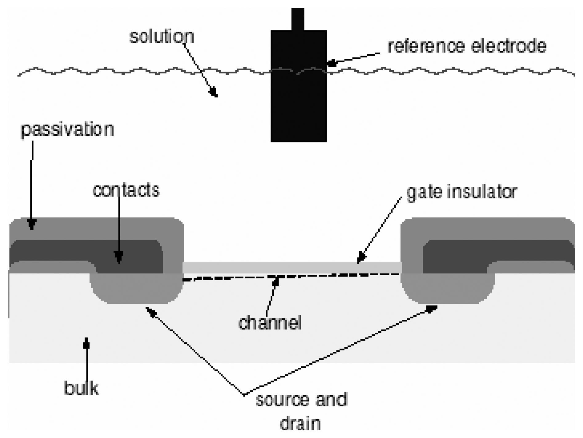
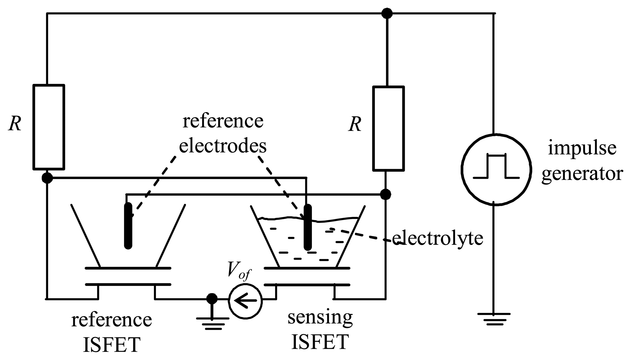
Essentially, the ISFET is a Metal-Oxide-Semiconductor FET (MOSFET) in which the standard metal-polysilicon gate is replaced by a more complex structure sensitive to the hydrogen-ion concentration. The gate structure, presented in
Fig. 1, consists of a reference electrode and an insulating material between which a measured electrolyte flows. The electrolyte closes the electric gate-source circuit and the ion concentration influences the gate potential, which in turns modifies the transistor's threshold voltage. In such a way, the hydrogen-ion concentration can exercise an electrostatic control on the drain-source current [
1].
The sensitivity of an ISFET is usually expressed as the gate-voltage change per decade of the hydrogen-ion concentration (pH), where the pH denotes -log [H+]. For example, if the value of the pH is equal to 2, the concentration of the hydrogen ions amounts to be 10-2 mole per liter.
As measurement method, the ISFET is usually operated in the constant drain-current mode, which means that the change of the drain current due to the change of the ion concentration in the electrolyte is compensated by the modification of the reference-electrode potential (the gate voltage). The gate voltage is usually measured by using an analog-to-digital converter (ADC) [
2,
3,
4].
This ordinary approach has several disadvantages. At first, to keep the drain current constant, additional electronics, whose inaccuracy can influence the resultant precision, is needed. Secondly, the hydrogen-ion concentration does not correspond directly to the gate voltage, only to a change of the gate voltage. In the third place, to represent the result in digital form, other ADC as separate electronic components are needed.
This contribution is devoted to a switched flip-flop-based preprocessing circuit for ISFETs. The principle of measurement consists in discontinuing the flip-flop value symmetry by the concentration of hydrogen ions (pH) and its recovering by a balanced voltage of which the magnitude is set automatically by using a feedback circuit. Authors of reference [
5] first used this idea in processing signals from chemical sensors. A switched flip-flop circuit with ISFETs is described in the following section.
Switched flip-flop with ISFETs
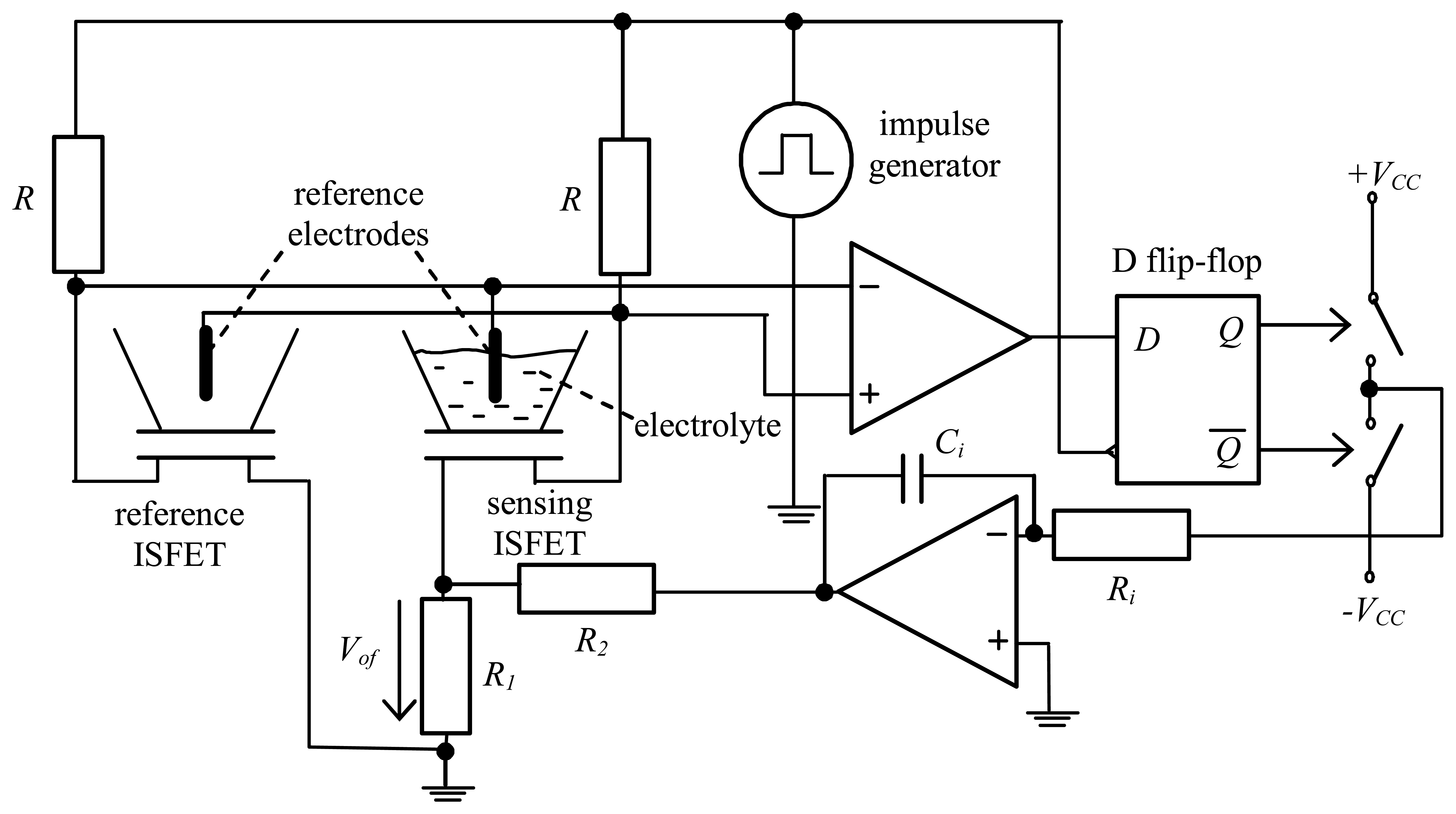
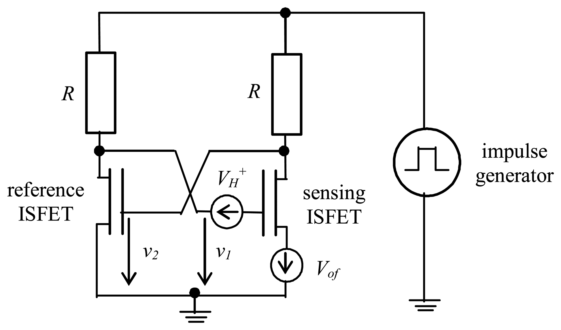
Fig. 2 shows a flip-flop with ISFETs. The circuit is controlled by an impulse generator and has two stable states, namely the states ‘one’ and ‘zero’. Activating the flip-flop with a voltage impulse, the circuit switches to one from two stable states [
6] and it depends on the asymmetry of the flip-flop which stable state it will be.
Let us consider the asymmetry caused by mismatches in the reference and sensing ISFET. Since, however, only the threshold voltage of the sensing ISFET is influenced by the H
+-ion concentration of the electrolyte, an equivalent circuit diagram according to
Fig. 3 can be drawn.
Here, the voltage source
VH+ represents the change of the sensing ISFET-threshold voltage by the value
(RgT/F).log
(H+) [
1], where
Rg is the gas constant,
T is the absolute temperature (K),
F is the Faraday constant and
H+ is the hydrogen-ion concentration. The principle of measurement is based on compensating this asymmetry by the balanced voltage
Vof. Compensating the flip-flop asymmetry we can achieve
v1=
v2 [
7]. Therefore, in a balanced state
Vof=-
(RgT/F).log
(H+). Then, when thermal and shot noise mean values being zero [
3], the probability of an ‘one’ and a ‘zero’ will be 0.5. This is known as the 50% state of a switched flip-flop [
7].
The symmetry of a real flip-flop can be discontinued by other disturbances such as the influence of flicker noise, mismatches in resistors, output characteristics of ISFETs, etc. As shown in [
8], the measured voltage
Vof is given by the formula
where
Voffset is the voltage needed to compensate the above disturbances. Thus, to eliminate the disturbances, two measurements must be performed, the measurement of
Voffset when the influence of H
+ ions is absent and the measurement of
Vof when the influence of H
+ ions is active. Then, a given chemical parameter can be calculated from
Equation (1). If, for example the, pH sensitivity is measured by using
eq. (1)where
pH=-log
(H+).
Measurement set-up
As explained in the previous section, the voltage
Vof reflects the hydrogen-ion concentration. To set the voltage automatically, a measurement set-up is chosen as depicted in
Fig. 4.
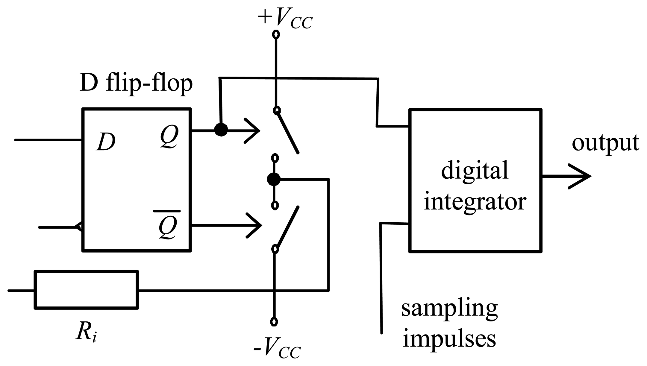
As can be seen, the feedback circuit contains an input differential amplifier, a D flip-flop, an integrator and a resistive divider. A differential amplifier processes the series of ‘ones’ and ‘zeros’ from the flip-flop output. The actual logical state is sampled by the D flip-flop and depending on this state, one of two switches is turned on. Thus, the resistive divider voltage is being decreased or increased to balance the switched flip-flop. By processing the series of impulses from the output Q of the D flip-flop, the chemical parameter to be measured is represented in digital form.
The system depicted in
Fig. 4 is a well-known Δ modulator [
4] in which the switched flip-flop serves as a comparator and a sampling circuit. To quantify the magnitude of the voltage
Vof, a digital integrator must be used (see
Fig. 5). A reversible counter can be used in the simplest case. Then, the voltage
Vof is given by the formula
where
N is the number of impulses read; the quantization step
Δ is given by the extension
The uncertainty, obtained from the rectangular probability of distribution of measured pH sensitivity is given by formula
For the dynamical properties of the measurement system let us consider that
Then, because of the maximal value of pH, the derivative of time
t can be written as
Here, the maximal measurable frequency
f of pH is given by the formula
Results of simulation and discussion
The measurement system pictured in
Fig. 4 was simulated in TSPICE. The approach which modifies the threshold voltage in dependence on the hydrogen ions in the existing SPICE MOSFET model was used for modelling the ISFET [
1]. Thus, the H
+-ion concentration induces the change of the threshold voltage of the sensing ISFET by the value
(RgT/
F).log
(H+). Other parameters of the used model are shown in
Tab. 1.
The remaining parameters were set as follows:
VCC = 5 V,
TS = 3.34*10
-5 s,
Ri = 200 kΩ,
Ci = 100 nF,
R1 = 200 Ω,
R2 = 10 Ω,
R = 6.8 k Ω, and
T = 294
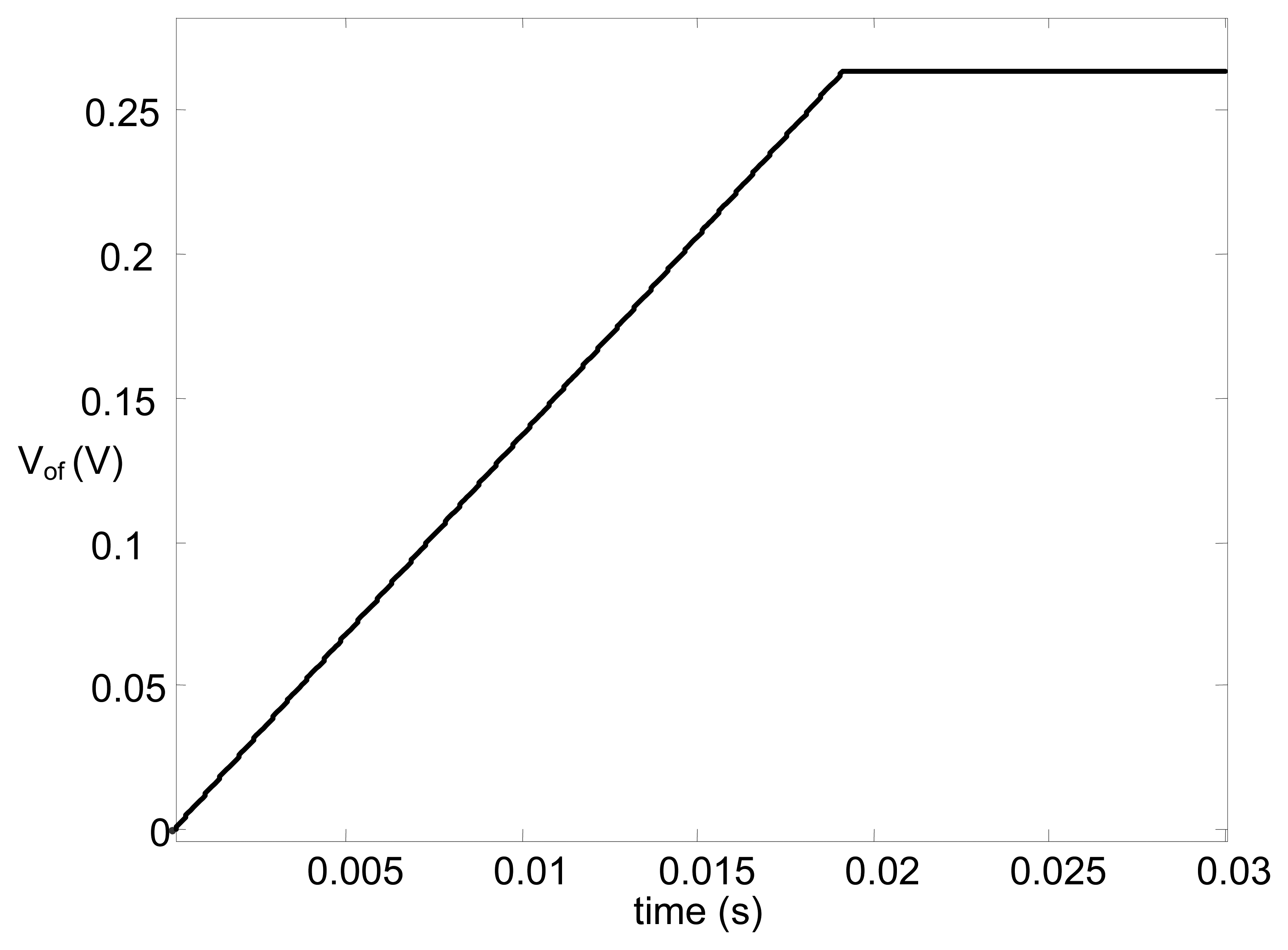
oK. At first, the value of pH 4.7 was chosen. The corresponding integrator input voltage and
Vof as functions of time are shown in
Figs. 6 and
7.
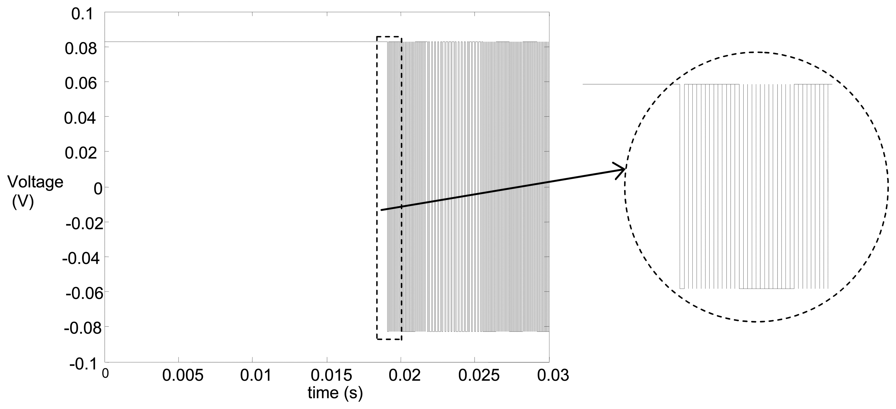
As shown in
Fig. 6, the voltage
Vof corresponding to pH 4.7 is obtained after 18 ms. At this moment, the positive impulses are generated only at the integrator input, whereas starting from this moment, the positive and negative impulses are generated statistically depending on the noise, as shown in
Fig. 7. For
t> 18 ms, the voltage
Vof changes from 0.2631 to 0.26337. Then, using
eq. (2) and assuming
Voffset= 0 and
RgT/
F= 56 mV/pH it follows that the pH changes from 4.698 to 4.703. Hence, the maximal relative error is 0.064 % in this case.
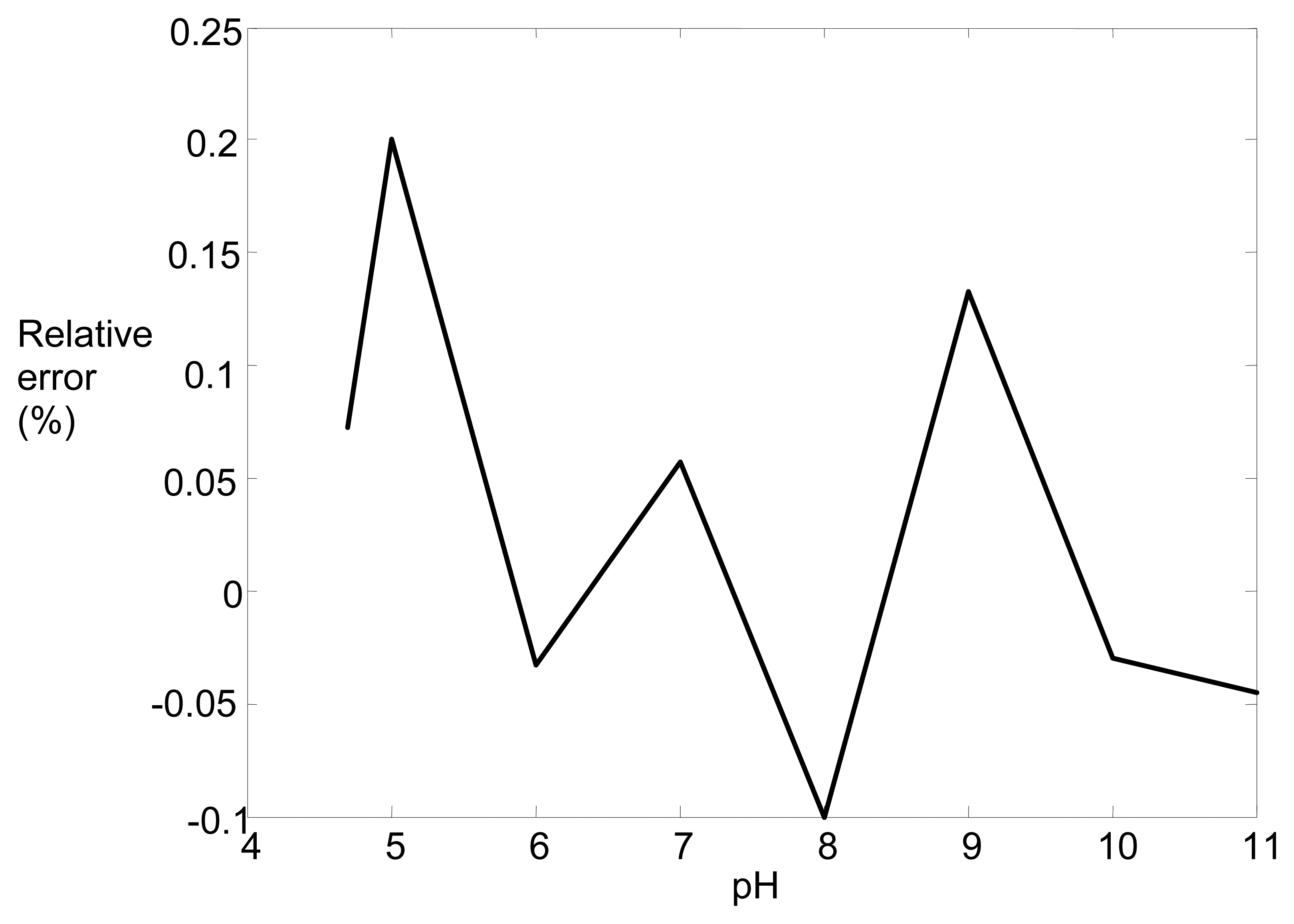
The pH was then changed from 4.7 to 11. The corresponding relative error characteristics is shown in
Figure 8. As can be seen, the maximal relative error is only 0.2%.
Conclusions
A preprocessing circuit for signals from ISFET has been presented. The main part is a switched flip-flop with a reference ISFET and a sensing ISFET. The principle of measurement is based on changing the threshold voltage of the sensing ISFET through the concentration of hydrogen-ion changes, thus discontinuing the symmetry of a switched flip-flop. This asymmetry is compensated by a voltage introduced to the flip-flop in such a way that the probability of ‘one’ equals to the probability of ‘zero’.
Through the simulation with TSPICE, it was shown that the relative error of the measured pH is in the worst case 0.22%. Our further work will focus on the practical realization of this circuit.


