

Measurement Modeling and Performance Analysis of a Bionic Polarimetric Imaging Navigation Sensor Using Rayleigh Scattering to Generate Scattered Sunlight

Abstract
:1. Introduction
- (1)
- An analysis method is proposed to analyze the influence of key error sources on the measurement performance of BPINS, including the influence of the degree of linear polarization and angle of E-vector. The proposed analysis method is generalized for all BPINSs.
- (2)
- The key error factors affecting the measurement accuracy of BPINS are quantitatively investigated using a skylight with a known polarization state generated by Rayleigh scattering as the incident light source, which is similar to the polarization pattern of an outdoor Rayleigh clear sky.
- (3)
- This work can guide the calibration of BPINS and provide a theoretical basis for the optimal design of BPINS. In addition to BPINS, the idea of this work can be applied to other polarimetric imaging applications such as polarimetric underwater detection, polarimetric defogging, polarimetric medical diagnostics, and so on.
2. Measurement Principle and Error Model of BPINS
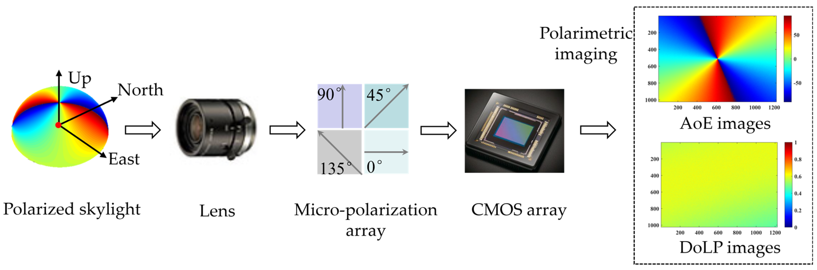
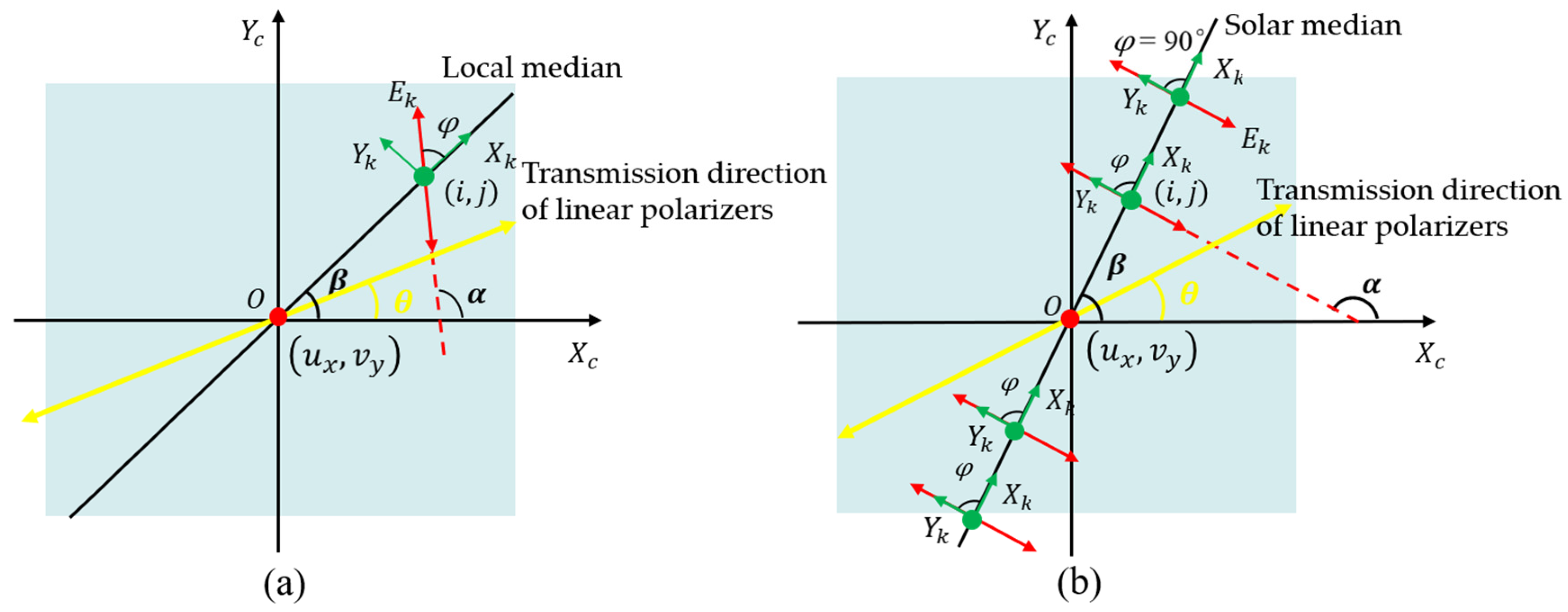
2.1. Principle of Skylight Polarimetric Imaging
2.2. Measurement Error Model of BPINS
- (1)
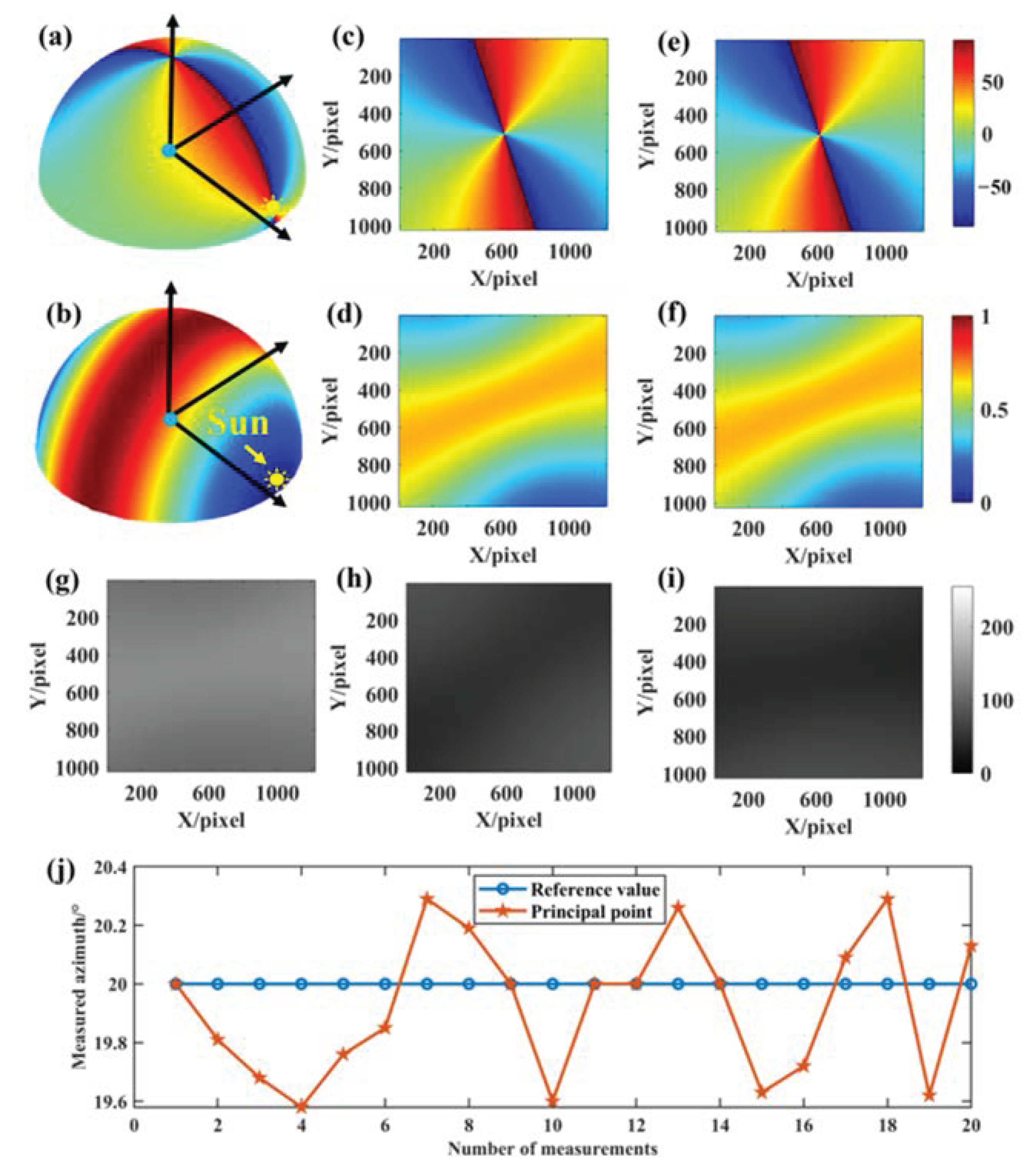
- Coordinate deviation of principal point
- (2)
- Installation angle error of micro-polarization array
- (3)
- Lens attenuation
- (4)
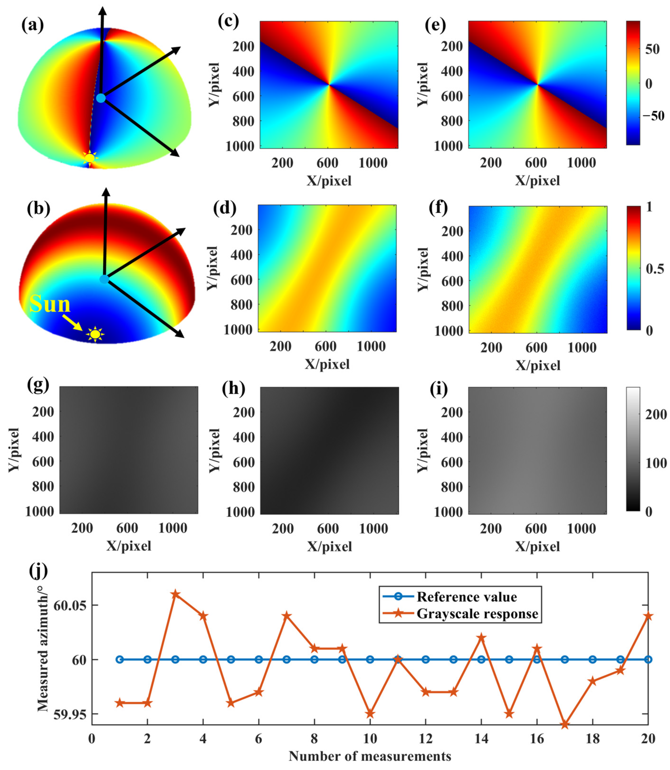
- Inconsistency of CMOS grayscale response
3. Performance Analysis Method for Generating Sunlight Using Rayleigh Scattering
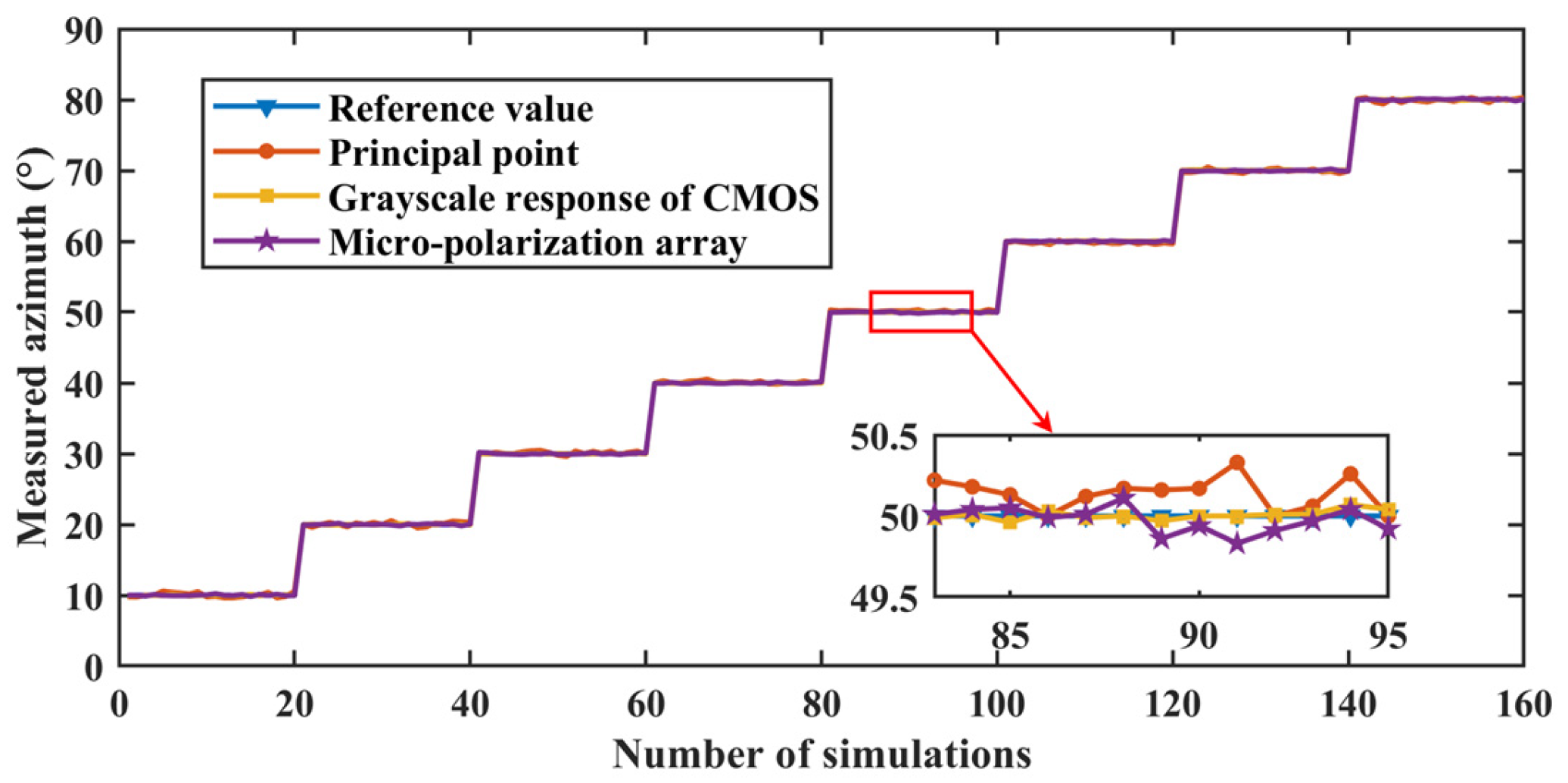
- Set different solar altitude and azimuth angles. We set the solar altitude angle to 5° during the simulation, and the solar azimuth angle to change every 10° between 10° and 80°.
- Reconstruct the skylight polarization distribution pattern at a certain time, and the skylight polarization distribution pattern can be reconstructed in the local geographical coordinate system according to the set solar altitude angle and azimuth angle and Rayleigh scattering model.
- Generate the truth values of the AoE image and DoLP image in the field of view. According to the theoretical BPINS projection model, CMOS and lens parameters, we can get the truth values of the two-dimensional AoE image and DoLP image from the three-dimensional skylight polarization distribution pattern reconstructed in step 2.
- Stokes vector representation and incidence of polarized skylight. The polarization state of incident light can be calculated from the truth value of the two-dimensional AoE image and DoLP image obtained in step 3, and the polarization state of incident light is represented by the Stokes vector.
- BPINS measurement model, set the error parameters of each device (Table 1), and polarized skylight with a known polarization state obtained from step 4 is incident into BPINS with measurement errors.
- CMOS imaging. Through the BPINS projection model, CMOS and lens parameters, we can get 0°, 45°, 90° direction intensity images.
- Polarimetric imaging calculation. The intensity images obtained in step 6 are used for polarimetric imaging calculation to obtain DoLP and AoE images containing measurement errors.
- Analyze the effect of single and combined factors on the measurement performance of BPINS. Repeat the above steps 1–7 to obtain multiple sets of DoLP and AoE images containing measurement errors, and then analyze the influence of errors on the measurement performance of BPINS.

4. Numerical Results
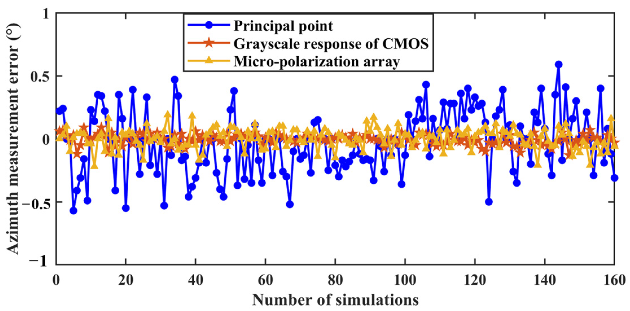
4.1. Effect of a Single Factor on the Measurement Performance of BPINS
4.2. Effect of Combined Factors on the Measurement Performance of BPINS
5. Conclusions
Author Contributions
Funding
Institutional Review Board Statement
Informed Consent Statement
Data Availability Statement
Conflicts of Interest
References
- Goldstein, D. Polarized Light, 3rd ed.; CRC Press: Boca Raton, FL, USA, 2010. [Google Scholar]
- Kuriyama, R.; Nakagawa, T.; Tatsumi, K.; Nakabe, K. Two-dimensional fluid viscosity measurement in microchannel flow using fluorescence polarization imaging. Meas. Sci. Technol. 2021, 32, 095402. [Google Scholar] [CrossRef]
- Wang, H.; Zhang, Q.; Ge, P.; Zhu, Y.; Wang, Y. Thermal radiation elimination method for high temperature digital image correlation using polarization camera. Meas. Sci. Technol. 2021, 32, 065203. [Google Scholar] [CrossRef]
- Zhu, Z.; Zhao, Y.; Liu, S.; Liu, Y.; Wang, W.; Tang, L. Calibration of line-structured light vision sensors based on simultaneous polarization imaging. Meas. Sci. Technol. 2022, 33, 115202. [Google Scholar] [CrossRef]
- Xia, L.; Liu, R.; Zhang, D.; Zhang, J. Polarized light-aided visual-inertial navigation system: Global heading measurements and graph optimization-based multi-sensor fusion. Meas. Sci. Technol. 2022, 33, 055111. [Google Scholar] [CrossRef]
- Li, S.; Kong, F.; Xu, H.; Guo, X.; Li, H.; Ruan, Y.; Cao, S.; Guo, Y. Biomimetic Polarized Light Navigation Sensor: A Review. Sensors 2023, 23, 5848. [Google Scholar] [CrossRef] [PubMed]
- Kong, F.; Guo, Y.; Zhang, J.; Fan, X.; Guo, X. Review on bio-inspired polarized skylight navigation. Chin. J. Aeronaut. 2023, 36, 14–37. [Google Scholar] [CrossRef]
- Horvath, G. Polarized Light and Polarization Vision in Animal Sciences; Springer: Berlin/Heidelberg, Germany, 2014. [Google Scholar]
- Cheng, K.; Jeffery, K.J. (Eds.) The Neurobiology of Spatial Behaviour. Anim. Cogn. 2004, 7, 1. [Google Scholar]
- Uwe, H. Sky compass orientation in desert locusts–evidence from field and laboratory studies. Front. Behav. Neurosci. 2015, 9, 346. [Google Scholar]
- Robin, G.; Fleischmann, P.N.; Kornelia, G.; Wehner, R.; Rössler, W. The role of celestial compass information in cataglyphis ants during learning walks and for neuroplasticity in the central complex and mushroom bodies. Front. Behav. Neurosci. 2017, 11, 226. [Google Scholar]
- Warren, T.L.; Giraldo, Y.M.; Dickinson, M.H. Celestial navigation in Drosophila. J. Exp. Biol. 2019, 222 (Suppl. S1), Jeb186148. [Google Scholar] [CrossRef]
- Ronacher, B. Path integration in a three-dimensional world: The case of desert ants. J. Comp. Physiol. 2020, 206, 379–387. [Google Scholar] [CrossRef]
- Horváth, G.; Varjú, D. Polarized Light in Animal Vision; Springer: Berlin/Heidelberg, Germany, 2004. [Google Scholar]
- Greif, S.; Borissov, I.; Yovel, Y.; Holland, R.A. A functional role of the sky’s polarization pattern for orientation in the greater mouse-eared bat. Nat. Commun. 2014, 5, 4488. [Google Scholar] [CrossRef] [PubMed]
- Patel, R.N.; Cronin, T.W. Mantis shrimp navigate home using celestial and idiothetic path integration. Curr. Biol. 2020, 30, 1981–1987. [Google Scholar] [CrossRef] [PubMed]
- Powell, S.B.; Garnett, R.; Marshall, J.; Rizk, C.; Gruev, V. Bioinspired polarization vision enables underwater geolocalization. Sci. Adv. 2018, 4, eaao6841. [Google Scholar] [CrossRef] [PubMed]
- Li, Q.; Dong, L.; Hu, Y.; Hao, Q.; Wang, W.; Cao, J.; Cheng, Y. Polarimetry for Bionic Geolocation and Navigation Applications: A Review. Remote Sens. 2023, 15, 3518. [Google Scholar] [CrossRef]
- Pham, K.D.; Chen, G.; Aycock, T.; Lompado, A.; Wolz, T.; Chenault, D. Passive optical sensing of atmospheric polarization for gps denied operations. Proc. SPIE 2016, 9838, 266–279. [Google Scholar]
- Lambrinos, D.; Moller, R.; Labhart, T.; Pfeifer, R.; Wehner, R. A mobile robot employing insect strategies for navigation. Robot. Auton. Syst. 2000, 30, 39–64. [Google Scholar] [CrossRef]
- Chu, J.; Zhao, K.; Qiang, Z.; Wang, T. Construction and performance test of a novel polarization sensor for navigation. Sens. Actuators A 2008, 148, 75–82. [Google Scholar] [CrossRef]
- Ma, T.; Hu, X.; Zhang, L.; He, X. Calibration of a polarization navigation sensor using the nsga-ii algorithm. Opt. Commun. 2016, 376, 107–114. [Google Scholar] [CrossRef]
- Wang, Y.; Chu, J.; Zhang, R.; Li, J.; Guo, X.; Lin, M. A bio-inspired polarization sensor with high outdoor accuracy and central-symmetry calibration method with integrating sphere. Sensors 2019, 19, 3448. [Google Scholar] [CrossRef]
- Chahl, J.; Mizutani, A. Biomimetic attitude and orientation sensors. IEEE Sensors J. 2011, 12, 289–297. [Google Scholar] [CrossRef]
- Dupeyroux, J.; Viollet, S.; Serres, J.R. An ant-inspired celestial compass applied to autonomous outdoor robot navigation. Robot. Auton. Syst. 2019, 117, 40–56. [Google Scholar] [CrossRef]
- Dupeyroux, J.; Diperi, J.; Boyron, M.; Viollet, S.; Serres, J. A bio-inspired celestial compass applied to an ant-inspired robot for autonomous navigation. In Proceedings of the European Conference on Mobile Robots (ECMR), Paris, France, 6–8 September 2017. [Google Scholar]
- Dupeyroux, J.; Diperi, J.; Boyron, M.; Viollet, S.; Serres, J. A novel insect-inspired optical compass sensor for a hexapod walking robot. In Proceedings of the IEEE/RSJ International Conference on Intelligent Robots and Systems (IROS), Vancouver, BC, Canada, 24–28 September 2017. [Google Scholar]
- Sturzl, W. A lightweight single-camera polarization compass with covariance estimation. In Proceedings of the IEEE International Conference on Computer Vision (ICCV), Venice, Italy, 22–29 October 2017. [Google Scholar]
- Liu, Z.; Zhang, R.; Wang, Z.; Guan, L.; Li, B.; Chu, J. Integrated polarization-dependent sensor for autonomous navigation. J. Micro/Nanolithography MEMS MOEMS 2015, 14, 015001. [Google Scholar] [CrossRef]
- Fan, C.; Hu, X.; Lian, J.; Zhang, L.; He, X. Design and calibration of a novel camera-based bio-inspired polarization navigation sensor. IEEE Sensors J. 2016, 16, 3640–3648. [Google Scholar] [CrossRef]
- Ren, H.; Yang, J.; Liu, X.; Huang, P.; Guo, L. 2020 Sensor modeling and calibration method based on extinction ratio error for camera-based polarization navigation sensor. Sensors 2020, 20, 3779. [Google Scholar] [CrossRef] [PubMed]
- Han, G.; Hu, X.; Lian, J.; He, X.; Zhang, L.; Wang, Y.; Dong, F. Design and calibration of a novel bio-inspired pixelated polarized light compass. Sensors 2017, 17, 2623. [Google Scholar] [CrossRef] [PubMed]
- Lu, H.; Zhao, K.; You, Z.; Huang, K. Angle algorithm based on hough transform for imaging polarization navigation sensor. Opt. Express 2015, 23, 7248–7262. [Google Scholar] [CrossRef] [PubMed]
- Tang, J.; Nan, Z.; Li, D.; Wang, F.; Zhang, B.; Wang, C.; Shen, C.; Ren, J.; Xue, C.; Liu, J. Novel robust skylight compass method based on full-sky polarization imaging under harsh conditions. Opt. Express 2016, 24, 15834. [Google Scholar] [CrossRef]
- Liang, H.; Bai, H.; Liu, N.; Sui, X. Polarized Skylight Compass Based on a Soft-Margin Support Vector Machine Working in Cloudy Conditions. Appl. Opt. 2020, 59, 1271. [Google Scholar] [CrossRef]
- Zhao, H.; Xu, W.; Zhang, Y.; Li, X.; Zhang, H.; Xuan, J.; Jia, B. Polarization patterns under different sky conditions and a navigation method based on the symmetry of the aop map of skylight. Opt. Express 2018, 26, 28589. [Google Scholar] [CrossRef]
- Wan, Z.; Zhao, K.; Li, Y.; Chu, J. Measurement error model of the bio-inspired polarization imaging orientation sensor. Opt. Express 2022, 30, 22–41. [Google Scholar] [CrossRef] [PubMed]
- Wang, S.; Qiu, Z.; Huang, P.; Yu, X.; Yang, J.; Guo, L. A Bioinspired Navigation System for Multirotor UAV by Integrating Polarization Compass/Magnetometer/INS/GNSS. IEEE Trans. Ind. Electron. 2023, 70, 8526–8536. [Google Scholar] [CrossRef]
- Li, G.; Zhang, Y.; Fan, S.; Wang, Y.; Yu, F. Robust Heading Measurement Based on Improved Berry Model for Bionic Polarization Navigation. IEEE Trans. Instrum. Meas. 2023, 72, 8500211. [Google Scholar] [CrossRef]
- Cheng, H.; Zhang, Q.; Wan, Z.; Zhang, Z.; Qin, J. Study on the polarization pattern induced by wavy water surfaces. Remote Sens. 2023, 15, 4565. [Google Scholar] [CrossRef]
- Cheng, H.; Zhang, D.; Zhu, J.; Yu, H.; Chu, J. Underwater target detection utilizing polarization image fusion algorithm based on unsupervised learning and attention mechanism. Sensors 2023, 23, 5594. [Google Scholar] [CrossRef] [PubMed]
- Liu, X.; Yang, J.; Li, W.; Huang, P.; Guo, L. Tightly Coupled Modeling and Reliable Fusion Strategy for Polarization-Based Attitude and Heading Reference System. IEEE Trans. Ind. Inform. 2023, 19, 62–73. [Google Scholar] [CrossRef]
- Jahne, B. Emva 1288 standard for machine vision—Objective specification of vital camera data. Optik Photonik. 2010, 5, 53–54. [Google Scholar] [CrossRef]
- Jiang, Y.; Li, Z. Monte carlo simulation of mueller matrix of randomly rough surfaces. Opt. Commun. 2020, 474, 126113. [Google Scholar] [CrossRef]
- Xiao, Y.; Zhou, L.; Chen, W. High-resolution ghost imaging through complex scattering media via a temporal correction. Opt. Lett. 2022, 47, 3692–3695. [Google Scholar] [CrossRef]
- Zhou, L.; Xiao, Y.; Chen, W. High-resolution self-corrected single-pixel imaging through dynamic and complex scattering media. Opt. Express 2023, 31, 23027–23039. [Google Scholar] [CrossRef]
- Cecconi, V.; Kumar, V.; Pasquazi, A.; Gongora, J.S.T.; Peccianti, M. Nonlinear field-control of terahertz waves in random media for spatiotemporal focusing. Open Res Europe 2023, 2, 32. [Google Scholar] [CrossRef]
- Vellekoop, I.M.; Mosk, A.P. Focusing coherent light through opaque strongly scattering media. Opt. Lett. 2007, 32, 2309–2311. [Google Scholar] [CrossRef]


| Error Sources | Distribution (μ, σ) | |
|---|---|---|
| Coordinate deviation of principal point | 0 | (2, 2) pixel |
| Installation angle error of micro-polarization array | 0 | 0.1° |
| Lens attenuation | 0 | (0.2, 0.2) |
| Grayscale response inconsistency of CMOS | 0 | 1 (DN) |
| Parameter | Specific Value | Unit |
|---|---|---|
| Pixel size | 3.45 × 3.45 | μm |
| Image resolution | (1024, 1224) | pixel |
| Focus length | 8 | mm |
| Principal point | (512.5, 612.5) | pixel |
| Error Sources | Azimuth Measurement Error (μ, σ) | |
|---|---|---|
| Coordinate deviation of principal point | −0.0237 | 0.2476 |
| Installation angle error of micro-polarization array | 0.0018 | 0.0812 |
| Grayscale response inconsistency of CMOS | 0.0059 | 0.0405 |
| Lens attenuation | 0.0 | 0.0 |
Disclaimer/Publisher’s Note: The statements, opinions and data contained in all publications are solely those of the individual author(s) and contributor(s) and not of MDPI and/or the editor(s). MDPI and/or the editor(s) disclaim responsibility for any injury to people or property resulting from any ideas, methods, instructions or products referred to in the content. |
© 2024 by the authors. Licensee MDPI, Basel, Switzerland. This article is an open access article distributed under the terms and conditions of the Creative Commons Attribution (CC BY) license (https://creativecommons.org/licenses/by/4.0/).
Share and Cite
Wan, Z.; Zhao, K.; Cheng, H.; Fu, P. Measurement Modeling and Performance Analysis of a Bionic Polarimetric Imaging Navigation Sensor Using Rayleigh Scattering to Generate Scattered Sunlight. Sensors 2024, 24, 498. https://doi.org/10.3390/s24020498
Wan Z, Zhao K, Cheng H, Fu P. Measurement Modeling and Performance Analysis of a Bionic Polarimetric Imaging Navigation Sensor Using Rayleigh Scattering to Generate Scattered Sunlight. Sensors. 2024; 24(2):498. https://doi.org/10.3390/s24020498
Chicago/Turabian StyleWan, Zhenhua, Kaichun Zhao, Haoyuan Cheng, and Peng Fu. 2024. "Measurement Modeling and Performance Analysis of a Bionic Polarimetric Imaging Navigation Sensor Using Rayleigh Scattering to Generate Scattered Sunlight" Sensors 24, no. 2: 498. https://doi.org/10.3390/s24020498