Lessons Learned about the Design and Active Characterization of On-Body Antennas in the 2.4 GHz Frequency Band


Biomedical Engineering Group, University of Seville, 41092 Seville, Spain
*
Author to whom correspondence should be addressed.
Sensors 2020, 20(1), 224; https://doi.org/10.3390/s20010224
Submission received: 30 October 2019
/
Revised: 12 December 2019
/
Accepted: 26 December 2019
/
Published: 31 December 2019
(This article belongs to the Special Issue Body Sensors Networks for E-Health Applications)
Abstract
:This work addresses the design and experimental characterization of on-body antennas, which play an essential role within Body Sensor Networks. Four antenna designs were selected from a set of eighteen antenna choices and finally implemented for both passive and active measurements. The issues raised during the process of this work (requirements study, technology selection, development and optimization of antennas, impedance matching, unbalanced to balanced transformation, passive and active characterization, off-body and on-body configurations, etc.) were studied and solved, driving a methodology for the characterization of on-body antennas, including transceiver effects. Despite the influence of the body, the antennas showed appropriate results for an in-door environment. Another novelty is the proposal and validation of a phantom to emulate human experimentation. The differences between experimental and simulated results highlight a set of circumstances to be taken into account during the design process of an on-body antenna: more comprehensive simulation schemes to take into account the hardware effects and a custom design process that considers the application for which the device will be used, as well as the effects that can be caused by the human body.
1. Introduction
Body sensor networks (BSN) are a promising solution to the challenges of personalized healthcare [1,2,3,4,5,6]. These body-centric communications are mainly developed in the 2.4 GHz frequency band using low-power technologies such as Bluetooth Low Energy (BLE) [7,8] or IEEE 802.15.4 [9,10,11,12,13] and IEEE 802.15.6 [14,15,16,17,18] standards. A critical element in BSN are the antennas [8,19,20,21,22] and their design specifications are especially crucial in the case of biomedical applications, in which small ultra-light devices, which suppose no hindrance on a subject’s daily life, are required. It is also desirable that they have a minimum consumption to reduce the need for battery recharge or change, and immunity against external interferences to safeguard the privacy of communications [4]. Other reasons include the need for efficient and secure bidirectional communication links, which allow the reprogramming and personalization of devices [3,4,5]. Although it is evident that during the last years important advances about the design and development of embedded antennas for micro-sized devices, even those with the capacity of in-body integration, have been achieved [20,23,24], both the aforementioned restrictions and design challenges, as well as the trade-off between the size of the antenna and its efficiency [25], highlight the need for advancing in research concerning portable technologies that permit the personalization and adaptation of communication systems in general, and in particular of antennas.
On the other hand, it must be considered that in BSN the antennas are arranged in devices located close to or in contact with the human body, a circumstance that may affect the performance of the antenna [22,26,27], which makes the recalculation of parameters necessary, in detriment of their efficiency, thus causing a trade-off to be made in each case. The characterization of BSN antennas is normally addressed without taking into account the effects of the transceiver itself and the consideration of a finite ground plane, which can greatly influence the antenna performance [28]. All of these, combined with the fact that the propagation mechanisms through the human body are not unknown in enough detail, underline the need for more exhaustive studies that analyze the influence of the human body on antennas and viceversa, to be undertaken [29].
The passive measurement inside an anechoic chamber is the standard method for the experimental characterization of antennas [8,21,27,29,30]. However, this method may be unsuitable if the characterization of the antenna integrated in a self-powered electronic device is required, given that the hardware components also influence the radiation characteristics [23,31]. In addition, it is possible that the antenna is matched to an impedance different from 50 ohms. In these cases it is common to use baluns, which can also influence the antenna results [32]. To the best of the authors’ knowledge, there is no standardized methodology for the experimental characterization of antennas integrated in self-powered electronic devices in the context of the BSN.
In this sense, this paper describes the issues encountered during the design and characterization process of a set of on-body antennas in anechoic chamber, and the solutions used to solve the problems found. This paper extends the work presented in [33] with the addition of three different antennas and a more detailed description of the requirements analysis, design, development and characterization procedures. Other extensions are a rational procedure for active measurements of BSN antennas integrated with the transceiver in battery-powered devices in order to obtain more realistic results, an analysis of the influence of the human body by means of on-body experimentation inside anechoic chamber and the proposal and validation of a phantom to emulate and facilitate human experimentation with antennas.
2. Materials and Methods
2.1. Issues Related to the Biomedical Application
The antenna will be integrated into a smart accelerometer sensor device called SoM (Sensor of Movement). This sensor is part of a low-cost e-Health system for fall detection [34]. The SoM is integrated in a biocompatible waterproof skin patch that is comfortably fixed on the back at the height of the sacrum for monitoring 24 h a day [34]. These circumstances impose to the antenna a minimum size, cost and weight, and as the device must have a long autonomy, energy efficiency is another major requirement.
The SoM is connected wirelessly with a device called DAD (Decision-Analysis Device), and this, in turn, with a remote healthcare center. The DAD is also carried by the person being monitored, although it can also be found in another position within the coverage area, either on an eventual or permanent basis. In this sense, the radiation pattern should be omnidirectional as far as possible.
Furthermore, as the wireless transmission is the major responsible for energy consumption in BSNs [4], information processing is distributed among the SoM and DAD to summarize and abstract the information transmitted with the consequent reduction of energy expenditure in communications [35].
To reduce the energy consumption in communications, only data are sent when an event susceptible of being considered a fall is detected [36]. In this way, low data rate is suitable for the communications link, and to support the personalization and adaptation of the SoM software, an efficient bidirectional link is required.
2.2. Issues Related to the Communication Technology Selection
Considering the needs established for the application (energy efficiency, low data rate, bidirectional link, etc.), IEEE 802.15.4 standard was chosen as the underlying communications technology [36] and Texas Instruments CC2431 transceiver was selected considering its low energy consumption and low cost [37]. According to the manufacturer’s specifications, new antenna requirements were established to ensure efficient and robust communications: input impedance close to ; the antenna should be balanced, or a balun should be added otherwise [37]; minimum return loss above 10 dB; bandwidth should safeguard the frequency spectrum between 2.403 and 2.482 GHz; gain such that a range of 5 m is guaranteed in communications. As low power is used, safety conditions are established (ANSI C95.1, ICNIRP) [38]. Given these restrictions, together with the fact that IEEE 802.15.4 works in the range of 2.4 GHz, printed circuit board (PCB) microstrip implementation was selected, against other alternatives such as chip or wired antennas, due to its low cost, simple implementation, high performance and small size in such frequency range.
2.3. Issues Related to the Design and Simulation Process
The preliminary conditions related to the antenna design were the following:
- A previously defined hardware design for the application case (fall detection): accelerometer, microcontroller and auxiliary components.
- The transceiver to be used is the CC2431 from Texas Instruments.
- Microstrip technology selected for the antenna design.
- The hardware defines a location of components, a top layer and a ground plane whose dimensions and size are optimized, which will not be modified during the antenna design process, so that the antenna will be incorporated into the previous hardware design.
The consideration of the electronics associated with the sensor device places additional requirements which makes difficult a single choice without testing the implications of transceiver, finite ground plane effects, sensor itself and body effects on performance. For that reason, several designs were considered. The particular choices were an attempt to balance the use of standard antenna design alternatives with the recommendations of the transceiver’s manufacturer.
Ansys HFSS software, based on electromagnetic finite-element-method (FEM), was used to design, optimize and simulate the radiation characteristics of the antennas (gain, return loss, radiation pattern, etc.). To obtain consistent simulation results, the output port impedance was renormalized to match the optimum load impedance of the transceiver.
The uncertainty about the implication of these preliminary conditions on overall performance (on-body operation, finite ground-plane effects, companion sensor electronics, etc.), suggested the consideration of several starting antenna designs. The particular choices balanced the use of standard topologies with the transceiver manufacturer recommendations:
- Eight designs derived from generic antennas: two types of monopole, three types of dipole, three types of circular antennas around the hardware, and a yagi antenna adapted to the microstrip technology [52].
The antenna design and optimization process was carried out as follows:
- Starting design of the antennas: All the antennas were implemented in the electromagnetic simulation software through different design tests for adaptation to a basic implementation of the sensor hardware that considered the dimensions of the ground plane and the thickness of the substrate. Figure 1 shows as an example an implementation of one of the analyzed antennas.
- Selection of sensitive dimensions: Through an analysis process, the dimensions that allowed the adjustment of the resonant frequency and bandwidth were selected.
- Iterative optimization process of the antennas: The radiation characteristics of each of the designs were optimized through an iterative adjustment of sizes, positions and values of the discrete impedance matching components (resistors, inductors, and capacitors). All the antennas were tuned by modifying the adjustable parameters of the antennas to meet the preliminary conditions related to the antenna design and to robustly comply with the design requirements established in the Section 2.2, maintaining a trade-off with the minimization of the device size. In general, the dimensions were changed iteratively to get, if possible, a resonant frequency centered around 2.45 GHz and return losses greater than 10 dB in the frequency range between 2.4 and 2.5 GHz.
- Sensitivity analysis of the antennas: On the selected dimensions a sensitivity analysis was performed to rule out those configurations very sensitive to small size changes.
- Evaluation of the radiation pattern of the antennas to select those configurations that provided a trade-off between the gain and an omnidirectional radiation pattern.
Table 1 summarizes the main results of the antennas under test, both the original and the adapted antennas after the iterative optimization process when this was possible. According to the simulations, the final four antenna designs showing best performance were selected for implementation (see Figure 2):
- Orthogonal Folded Dipole (OFD): A folded dipole with balanced output, but with an orthogonal shape in order to be adapted to the circuit size, thus reducing the overall size of the device. The use of a balun is not necessary since OFD is already a balanced antenna.
- Matched Folded Dipole (MFD): A modification of a folded dipole in order to follow to the shape of the device, thus reducing the overall size.
- Modified MIFA (MIFAm): Despite its small size, this antenna is not balanced. Therefore, an additional balun was designed according to the characteristics of both antenna and sensor device.
- Modified IFA (IFAm): It requires a larger surface and needs to be matched with a balun too.
2.4. Issues Related to the Anechoic Chamber Measurements
The experimental characterization of the antennas was carried out inside an electromagnetic anechoic chamber. Figure 3 shows two pictures of the interior of the anechoic chamber. To avoid the electromagnetic compatibility problems caused by the metallic support of the transmitter (Tx) antenna, a non-conductive PVC (polyvinyl chloride) support was manufactured, since this material has dielectric properties similar to air. This solution has already been used in other works because of its low cost and because it allows to manufacture very robust structures by assembling plumbing pipes and joints [53,54,55,56]. The effects of this type of support have been considered negligible in some studies [57]. The internal space of the support and the metallic components were covered by the same electromagnetic radiation attenuation absorbers as those used on the anechoic chamber walls. Although the effects of the metal support cannot be completely removed, it is a suitable solution to approach a free space situation [56]. Figure 4 shows a diagram of the non-conductive support and the arrangement of the Tx antenna on it.
According to transceiver restrictions, the antennas are balanced and with input impedance close to . As the measurement equipment (HP8510-B automatic vector network analyzer of HP) input was unbalanced, a impedance network and a balun [58] were included in a first set of prototypes (P1) to perform the single-ended to differential conversion, and match the antenna impedance to the measurement equipment (see Figure 5).
However, the received signal from the passive prototypes was very weak, possibly due to losses in the impedance matching network. To solve this problem, and although another type of balun or impedance matching network could have been used to feed the antennas from network analyzer of the anechoic chamber, it was decided to go one step further and propose a different solution to the standard method based on passive measurements. Instead, antenna performance was evaluated in their context of use, including all the hardware associated with the portable device in which the antenna would be located. In this case, the transceiver itself is the one that generates the antenna’s power signal, which is powered by the battery of the portable device. This method proposes to be a more realistic approach to the conditions of use of the antenna, incorporating the external elements and effects that can influence the operation of the antennas.
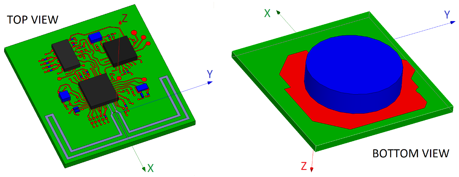
To address this issue, four complete SoM prototypes (P2) were implemented, each of them with its own battery supply and one of the selected antennas connected to the transceiver (see Figure 5). The advantage of this configuration is that the effects derived from the hardware of the device (shape, dimensions, electronic and metallic components, properties of the PCB, etc.) are integrated into the experimental characterization, but also remove the effects caused by the long cables that connect the Tx antenna to the measuring equipment. A lithium button cell model CR2032 was used to power the prototypes. This battery was located at the bottom of the PCB on a battery holder. The location of the battery is shown in Figure 5. Details about the consumption of the device were commented in [36].
Since the transceiver could not be configured to transmit continuously (the communications protocol requires the use of listening periods), a duty cycle of 81.72% was achieved by activating sequentially and successively the transmission and reception of data for 5.472 ms and 1.224 ms, respectively. The selected transmission frequency was 2.4448 GHz, since it is located at an intermediate point of the transmission range. However, a stable measurement of the network analyzer was not possible due to the continuous phase changes that occur in the carrier as a result of the use of the IEEE 802.15.4 standard protocol. To solve this issue, a FSL8 spectrum analyzer of Rohde & Schwarz was used.
Figure 3 shows the arrangement of the measurement elements inside the anechoic chamber, as well as the definition of the planes (azimuth and elevation) used to characterize the radiation diagrams of the antennas taking as reference the sensor position described in Section 2.1.
The azimuth plane pattern was obtained setting the roll angle to 90° and measuring at different azimuth angles with a separation of 1°. The correspondence between angles was set considering the schemes shown in Figure 3. The spectrum analyzer was configured with zero span option at the Tx frequency and the power level received was averaged to assume the duty cycle discontinuity by setting a sweep time of 80 s for 501 samples. Three measurements were performed for each of the positions in different time instants. A larger number of measurements was not considered due to the low variability and the average was considered as the final value. When any element of the support could obstruct the direct sight path between the Tx and the receiver (Rx), a specular position of the metal support on the azimuth rotation axis was established by modifying the azimuth and roll angles but keeping the antenna in a configuration equivalent to the initial position. The elevation plane pattern was obtained setting the azimuth angle to 270° and measuring at different roll angles in increments of 1°. In the same way, three measurements were taken for each orientation. This procedure was repeated for each of the antennas.
The antennas were characterized in four different configurations for a more comprehensive evaluation:
- Off-body: This condition was emulated following the procedure described above using the non-conductive PVC support and electromagnetic radiation attenuation absorbers inside the support as Figure 4 shows.
- Phantom to emulate on-body condition (separated): In this case, the space between the antenna and the metal support was occupied by a phantom of biological material to emulate the presence of the human body. Containers of liquids or gels that simulate the electrical properties of the body tissues have been used [29], but in this work a biological material of similar structure (skin, fat and muscle) is proposed. A chicken for food consumption was selected to implement the phantom (2.45 kg, clean inside, featherless at room temperature), which was fixed to the support. The phantom was covered by a very thin film (15 μm) of non-conductive material (polyethylene and polypropylene) to prevent electrical conduction effects. The antenna was arranged to maintain a separation of 0.5 cm from the surface of the phantom and located over the center of the area corresponding to the breast.
- Phantom to emulate on-body condition (fixed): Equivalent to the previous condition, but in this case the sensor was arranged in direct contact with the surface of the phantom. The side of the PCB (FR4 epoxi) in contact with the phantom surface was free of copper, and the antenna was located on the opposite side of the PCB.
- On-body: In this case, the metallic support was discarded, placing on its position a volunteer (male, 42 years of age, height of 1.73 cm and weight of 82 kg). Each of the P2 prototypes were placed on the volunteer according to Section 2.1. In each experiment, the volunteer oriented himself inside the anechoic chamber towards a fixed azimuth angle using a system of visual references. The average value of thirty measurements was recorded. A greater number of measurements was necessary in this case to estimate the mean value due to the increase in variability as a consequence of performing measurements on a person. Different experiments were carried out to go through the azimuthal plane in increments of 15°. In order to obtain the elevation plane pattern, the volunteer was oriented in a direction transverse to the line connecting Tx with Rx, manually varying the orientation angle of the sensor on the volunteer’s back in increments of 15° in each of the experiments.
3. Results
3.1. Simulation Results
Figure 6 shows some of the simulation results of the implemented antennas. OFD antenna has an omnidirectional radiation pattern in the normal plane to the antenna. It meets the return loss specification over all the frequency range and provides a very high bandwidth, around 400 MHz. MFD bandwidth decreases compared with that presented by the OFD. MIFAm and IFAm antennas robustly meet the return loss profile and they also present a large bandwidth. The gain of all the antennas is suitable for a BSN application (5-m communication range guaranteed) and their radiation pattern is omnidirectional in the azimuth plane. On the other hand, the high bandwidth obtained in all the cases makes them robust against possible mismatches due to a poor repeatability in the PCB implementation.
3.2. Anechoic Chamber Results
The gain of the Tx antenna was estimated using Friis Transmission Equation from the average received power. For the calculations, a transmitted power of 0 dBm (value set in the CC2431 transceiver) was considered, a Rx antenna gain of 8.575 dB (LB-20245 of AINFO Inc., according to the manufacturer’s specifications at 2.4448 GHz), a transmission distance of 5.105 m and a correction factor of 1.224 to take into account the attenuation caused by the duty cycle. Both azimuth and elevation planes patterns are shown in Figure 7 and Figure 8 for the different evaluations inside the anechoic chamber and referenced over the simulated results.
In order to allow a comparison between the simulation and the experimental results, the different radiation patterns are shown together. The radiation patterns in the elevation and azimuth planes are shown according to the angles and orientations described in Figure 3. The simulation results have been obtained using the HFSS software and the experimental results inside the anechoic chamber. Simulation results are shown in thick solid line and black color using the basic model described in the Section 2.3 that included the antenna, the substrate and the ground plane. A narrow dotted line in red color shows the results of the off-body experiment inside the anechoic chamber using the non-conductive PVC support and attenuation prisms to emulate a free space condition. The narrow solid line in green color corresponds to the experiments with the biological phantom inside the PVC support and the antenna 0.5 cm apart from it. The narrow dashed line in blue color shows the results with the biological phantom, but in this case without any separation. The radiation patterns of the antenna in a realistic situation on a person’s body is described in narrow dotted line and black color.
Given the disagreements between the simulation and experimental results, it was considered convenient to repeat the simulations including in the models the metallic elements that make up the tracks and pads of the sensor hardware, as well as the battery and other dielectric and conductive elements related to the electronic components. Figure 9 shows by way of example the realistic representation of the model related to one of the antennas (OFD). Such simulation is superimposed on the radiation diagrams of Figure 7 and Figure 8 as a thick dashed line in black color.
4. Discussion
A mismatch between the experimental results and simulations can be observed in Figure 7 and Figure 8. Probable causes of the differences may be the losses attributable to the elements not considered in the design and simulation phase: uncertainties due to the manufacturing process, calibration or measurement errors, finite ground plane effects, influence of the metallic and electronic components of the device’s complete hardware, properties of the transceiver and the communications protocol, but also other losses derived from the front-end of the measurement equipment, such as possible signal losses by impedance mismatch in the Tx or Rx antennas, in the coaxial cable that connects them to the spectrum analyzer or in the connectors [59,60,61,62,63,64]. It was not possible to perform any type of calibration to remove the losses associated with the transceiver interfaces, since it was not possible to establish any reference in the received signal if the battery-powered transceiver was used as transmitter.
However, this work contributed a methodology for the evaluation of the performance of antennas integrated in the complete hardware of a portable device, including the battery. This proposed procedure differs from the standard method for the passive evaluation of antennas inside an anechoic chamber using a network analyzer with antennas matched to 50-ohm. Under normal circumstances, the standard method provides an effective way to evaluate antenna performance, with good correspondence between the simulation results and the experimental results. However, sometimes these differences can be important as a result of the loss of control in the elements that influence the antennas or external effects [60,61,62,63,64,65,66]. The proposed method, despite its higher complexity, assumes many of the effects that can influence the performance of the antennas, so it can represent a better approach to reality.
Although the simulation with basic elements of the antenna and the ground plane reported differences with respect to the experimental results in all the cases analyzed, similar results have been found in other studies with antennas for personal communications [67,68]. To address this issue, a more realistic simulation was performed including explicitly the main hardware elements that can affect the radiation characteristics of the antenna (metallic elements of the PCB, battery, etc.). The realistic simulation was closer to the experimental results in all the cases. In the particular case of OFD and MFD antennas, realistic simulation largely coincided with the results in off-body experiments. On the other hand, in the elevation plane, the differences, although minor, were around 10 dB. A possible cause of these discrepancies may be related to losses due to the polarization of the antennas. Greater differences between the realistic and experimental simulation were found in the cases of the MIFAm and IFAm antennas, which can be due to the greater complexity of these antennas, and therefore to the increase in the number of elements that may affect their performance. It should be remembered that both antennas include a balun.
The results obtained with the proposed phantom (a featherless chicken for food consumption) were qualitatively and quantitatively equivalent to those obtained in on-body experimentation. The main advantage offered by this phantom is that it allows the use of the automatic positioning system of the anechoic chamber (roll and azimuth). This would favor the agility of experimentation and the possibility of tackling in a simple way orientations and positions difficult to evaluate in human experimentation.
If the results obtained with the phantom are analyzed, a configuration in which the sensor is separated from the surface of the body is slightly beneficial with respect to another configuration in which the sensor is fixed on the surface thereof.
Despite the influence of the body, the four antennas showed a fairly omnidirectional behavior, which is beneficial for the use application of the sensor. In addition, although there are important differences regarding the simulation, the experimental results are considered sufficient for an in-door environment. The worst performances were obtained for the MIFAm antenna, but the other antennas showed similar behavior.
5. Conclusions
This work has analyzed the issues raised during the design, development and characterization processes of a set of on-body antennas. The first point was to analyze the needs derived from the application where the antennas will be used. The second point was to address the communication technology issues (selection of the communication link technology, new requirements associated, antenna type selection, etc.). Eighteen different antenna designs were performed and optimized using an electromagnetic simulation software through an iterative adjustment of sizes, positions and impedance matching components. The final four antenna designs showing best performance in simulation were selected for implementation and experimental characterization.
The common method for antenna characterization, passive antenna measurement in an anechoic chamber, was discarded due to the weak levels of the received signal. The cause of this problem was possibly the losses in the impedance matching network used to match the antennas to the measuring equipment: single-ended to differential conversion; 50-Ohm measurement equipment impedance matching.
To deal with these issues, active characterization of the antennas was performed following a specific procedure conceived for the analysis of assembled antennas in self-powered devices. This method enables the evaluation of the antenna performance in conditions close to reality, including the effects caused by the hardware (the shape and size of the metal and dielectric elements of the circuit, the influence of electronic components or the effects derived of the transceiver and the communications protocol, among others), but also removing unwanted effects derived from the Tx front-end of the measurement equipment, such as possible signal losses in the coaxial cable or caused by impedance mismatch in the antenna and connectors. The problems caused by the communications protocol were solved with the use of a spectrum analyzer instead of a network analyzer. The effects caused by the human body in the context of a BSN were analyzed through on-body experimentation. In addition, it has been proposed and validated the use of a phantom to emulate the on-body experimentation inside an anechoic chamber, suitable for a rapid preliminary assessment unconstrained by the limitations that the automatic positioning and orientation of the human body would have.
A realistic simulation of the elements that make up the hardware of self-powered devices made it possible to verify that the battery and the metallic elements close to the antenna affect its performance. The experimental results were closer to the simulation results when the conductive elements that make up the PCB hardware are explicitly included in the simulations. Generic electromagnetic simulation tools are not prepared to model and simulate these components close to the antennas. It is advisable to develop new and more comprehensive design and simulation schemes that allow incorporating the effects of the complete hardware of the device in which the antenna would be integrated; the presence of the human body and its effects should be incorporated into a custom design process, adapted to the specific application of use; and, to minimize possible deviations from the design requirements, it is advisable to incorporate a cycle of iterative spiral development with intermediate experimental evaluation stages.
Author Contributions
All authors have participated actively in the development of this work. Conceptualization, D.N.-H., J.R.-T. and L.M.R.; Methodology, D.N.-H., J.R.-T. and L.M.R.; Software, D.N.-H.; Validation, D.N.-H.; Formal Analysis, D.N.-H., J.R.-T. and L.M.R.; Investigation, D.N.-H., J.R.-T. and L.M.R.; Writing Original Draft Preparation, D.N.-H.; Writing Review & Editing, D.N.-H. and J.R.-T.; Supervision, J.R.-T. and L.M.R.; Project Administration, J.R.-T. and L.M.R.; Funding Acquisition, J.R.-T. and L.M.R. All authors have read and agreed to the published version of the manuscript.
Funding
This work was supported in part by the “Fondo de Investigaciones Sanitarias” (Instituto de Salud Carlos III, Spain) under Grants PI15/00306, in part by the “Fundación Progreso y Salud” (Government of Andalucía, Spain) under Grant PIN-0394-2017, in part by “Fundación Mutua Madrileña” under grant VÍA-RENAL, and in part by the “Eurostars Programme”, European Commission, under Grant “FRAIL”.
Acknowledgments
The authors would like to thank Francisco Medina-Mena, Vicente Losada-Torres, Gerardo Barbarov-Rostán and Verónica Roldán-Porras for their helpful support.
Conflicts of Interest
The authors declare no conflict of interest. The founding sponsors had no role in the design of the study; in the collection, analyses, or interpretation of data; in the writing of the manuscript, and in the decision to publish the results.
Abbreviations
The following abbreviations are used in this manuscript:
| BLE | Bluetooth Low Energy |
| BSN | Body sensor network |
| DAD | Decision-Analysis Device |
| FEM | Finite-element-method |
| IFA | Inverted F antenna |
| IFAm | Modified IFA |
| MFD | Matched folded dipole |
| MIFA | Meandered inverted F antenna |
| MIFAm | Modified MIFA |
| OFD | Orthogonal folded dipole |
| PCB | printed circuit board |
| PVC | Polyvinyl chloride |
| P1 | First set of prototypes |
| P2 | Complete SoM prototypes |
| Rx | Receiver |
| SoM | Sensor of Movement |
| Tx | Transmitter |
References
- Chen, C.; Wang, Z.; Li, W.; Chen, H.; Mei, Z.; Yuan, W.; Tao, L.; Zhao, Y.; Huang, G.; Mei, Y.; et al. Novel flexible material-based unobtrusive and wearable body sensor networks for vital sign monitoring. IEEE Sens. J. 2019, 19, 8502–8513. [Google Scholar] [CrossRef]
- Niu, S.; Matsuhisa, N.; Beker, L.; Li, J.; Wang, S.; Wang, J.; Jiang, Y.; Yan, X.; Yun, Y.; Burnett, W.; et al. A wireless body area sensor network based on stretchable passive tags. Nat. Electron. 2019, 2, 361–368. [Google Scholar] [CrossRef]
- Pirbhulal, S.; Zhang, H.; Wu, W.; Mukhopadhyay, S.; Zhang, Y. Heart-beats based biometric random binary sequences generation to secure wireless body sensor networks. IEEE Trans. Biomed. Eng. 2018, 65, 2751–2759. [Google Scholar] [CrossRef] [PubMed]
- Fernandes, D.; Ferreira, A.; Abrishambaf, R.; Mendes, J.; Cabral, J. Survey and taxonomy of transmissions power control mechanisms for wireless body area networks. IEEE Commun. Surv. Tutor. 2018, 20, 1292–1328. [Google Scholar] [CrossRef]
- Mihovska, A.; Sarkar, M. Smart Connectivity for Internet of Things (IoT) Applications. In New Advances in the Internet of Things; Studies in Computational Intelligence; Yager, R.R., Espada, J.P., Eds.; Springer: Berlin/Heidelberg, Germany, 2018. [Google Scholar]
- Wan, J.; Al-awlaqi, M.; Li, M.; O’Grady, M.; Gu, X.; Wang, J.; Cao, N. Wearable IoT enabled real-time health monitoring system. Eurasip J. Wirel. Commun. Netw. 2018, 298, 1–10. [Google Scholar] [CrossRef]
- Perumal, K.; Manoharan, P. A comparative analysis of energy-efficient protocols for WBAN on heterogeneous transceivers. J. Test. Eval. 2019, 47, 3912–3927. [Google Scholar] [CrossRef]
- Dumanli, S.; Sayer, L.; Mellios, E.; Fafoutis, X.; Hilton, G.; Craddock, I. Off-body antenna wireless performance evaluation in a residential environment. IEEE Trans. Antennas Propag. 2017, 65, 6076–6084. [Google Scholar] [CrossRef] [Green Version]
- Badreddine, W.; Chaudet, C.; Petruzzi, F.; Potop-Butucaru, M. Broadcast strategies and performance evaluation of IEEE 802.15.4 in wireless body area networks WBAN. Ad Hoc Netw. 2020, 97, 102006. [Google Scholar] [CrossRef] [Green Version]
- Rismanian Yazdi, F.; Hosseinzadeh, M.; Jabbehdari, S. A priority-based MAC protocol for energy consumption and delay guaranteed in Wireless Body Area Networks. Wirel. Pers. Commun. 2019, 108, 1677–1696. [Google Scholar] [CrossRef]
- Ngo, M.; La, Q.; Leong, D.; Quek, T.; Shin, H. User behavior driven mac scheduling for body sensor networks: A cross-layer approach. IEEE Sen. J. 2019, 19, 7755–7765. [Google Scholar] [CrossRef]
- Rezaie, H.; Ghassemian, M. An adaptive algorithm to improve energy efficiency in wearable activity recognition systems. IEEE Sens. J. 2017, 17, 5315–5323. [Google Scholar] [CrossRef]
- Velusamy, B.; Pushpan, S. An enhanced channel access method to mitigate the effect of interference among Body Sensor Networks for smart healthcare. IEEE Sens. J. 2019, 19, 7082–7088. [Google Scholar] [CrossRef]
- Hasan, K.; Biswas, K.; Ahmed, K.; Nafi, N.; Islam, M. A comprehensive review of wireless body area network. J. Netw. Comput. Appl. 2019, 143, 178–198. [Google Scholar] [CrossRef]
- Saboor, A.; Ahmad, R.; Ahmed, W.; Kiani, A.; Moullec, Y.; Alam, M. On research challenges in hybrid medium-access control protocols for IEEE 802.15.6 WBANs. IEEE Sens. J. 2019, 19, 8543–8555. [Google Scholar] [CrossRef]
- Vera, D.; Costa, N.; Roda-Sanchez, L.; Olivares, T.; Fernández-Caballero, A.; Pereira, A. Body area networks in healthcare: A brief state of the art. Appl. Sci. 2019, 9, 3248. [Google Scholar] [CrossRef] [Green Version]
- Rikli, N.E.; Al-Mazroa, A. Design of an adaptive medium access control protocol for wireless body area networks with heterogeneous sensors. Int. J. Distrib. Sens. Networks 2019, 15. [Google Scholar] [CrossRef] [Green Version]
- Wang, J.; Sun, Y.; Ji, Y.; Luo, S. Priority-aware price-based power control for co-located WBANs using stackelberg and bayesian games. Sensors 2019, 19, 2664. [Google Scholar] [CrossRef] [Green Version]
- Felicio, J.; Costa, J.; Fernandes, C. Dual-band skin-adhesive repeater antenna for continuous body signals monitoring. IEEE J. Electromagn. Microwaves Med. Biol. 2018, 2, 25–32. [Google Scholar] [CrossRef]
- Bose, P.; Khaleghi, A.; Balasingham, I. In-body and off-body channel modeling for future leadless cardiac pacemakers based on phantom and animal experiments. IEEE Antennas Wirel. Propag. Lett. 2018, 17, 2484–2488. [Google Scholar] [CrossRef]
- Sáchez-Montero, R.; Camacho-Gómez, C.; López-Espí, P.; Salcedo-Sanz, S. Optimal design of a planar textile antenna for industrial scientific medical (ISM) 2.4 GHz wireless body area networks (WBAN) with the CRO-SL algorithm. Sensors 2018, 18, 1982. [Google Scholar] [CrossRef] [Green Version]
- Mohamadzade, B.; Hashmi, R.; Simorangkir, R.; Gharaei, R.; Rehman, S.; Abbasi, Q. Recent advances in fabrication methods for flexible antennas in wearable devices: State of the art. Sensors 2019, 19, 2312. [Google Scholar] [CrossRef] [PubMed] [Green Version]
- Magill, M.; Conway, G.; Scanlon, W. Tissue-independent implantable antenna for in-body communications at 2.36–2.5 GHz. IEEE Trans. Antennas Propag. 2017, 65, 4406–4417. [Google Scholar] [CrossRef] [Green Version]
- Wen, D.; Hao, Y.; Munoz, M.; Wang, H.; Zhou, H. A compact and low-profile MIMO antenna using a miniature circular high-impedance surface for wearable applications. IEEE Trans. Antennas Propag. 2018, 66, 96–104. [Google Scholar] [CrossRef]
- Pfeiffer, C. Fundamental efficiency limits for small metallic antennas. IEEE Trans. Antennas Propag. 2017, 65, 1642–1650. [Google Scholar] [CrossRef] [Green Version]
- Li, Y.; Kim, Y. Classification of human activities using variation in impedance of single on-body antenna. IEEE Antennas Wirel. Propag. Lett. 2017, 16, 541–544. [Google Scholar] [CrossRef]
- Soh, P.; Vandenbosch, G. Textile antennas for body area networks: Design strategies and evaluation methods. In Electromagnetics of Body-Area Networks: Antennas, Propagation, and RF Systems; Wiley: Hoboken, NJ, USA, 2016; pp. 1–25. [Google Scholar]
- Cheng, S.; Hallbjorner, P.; Rydberg, A.; Vanotterdijk, D.; van Engen, P. T-matched dipole antenna integrated in electrically small body-worn wireless sensor node. Microwaves Antennas Propag. 2009, 3, 774–781. [Google Scholar] [CrossRef]
- Tsolis, A.; Paraskevopoulos, A.; Alexandridis, A.; Whittow, W.; Chauraya, A.; Vardaxoglou, J. Design, realisation and evaluation of a liquid hollow torso phantom appropriate for wearable antenna assessment. Microwaves Antennas Propag. 2017, 11, 1308–1316. [Google Scholar] [CrossRef] [Green Version]
- Ferreira, D.; Pires, P.; Rodrigues, R.; Caldeirinha, R. Wearable textile antennas: Examining the effect of bending on their performance. IEEE Antennas Propag. Mag. 2017, 59, 54–59. [Google Scholar] [CrossRef]
- Popa, I.; Janhunen, J.; Mikhaylov, K. Performance evaluation of ZigBee and UWB wireless sensors under doppler effect in rotating mechanical structures. In Proceedings of the European Wireless Conference 2016, Oulu, Finland, 18–20 May 2016; pp. 488–493. [Google Scholar]
- Baker, D.; Du Toit, J. A compact 1 to 18 GHz planar spiral antenna for interferometer and other direction finding applications. In Proceedings of the IEEE-APS Topical Conference on Antennas and Propagation in Wireless Communications (APWC), Cape Town, South Africa, 2–7 September 2012; pp. 1016–1019. [Google Scholar]
- Naranjo, D.; Roa, L.; Reina, L.; Barbarov, G.; Callejón, A. Experimental characterization of active antennas for body sensor networks. In Proceedings of the XIII Mediterranean Conference on Medical and Biological Engineering and Computing, Seville, Spain, 25–28 September 2013; Volume 41, pp. 1853–1856. [Google Scholar]
- Naranjo, D.; Roa, L.; Reina, J.; Estudillo, M. Personalization and adaptation to the medium and context in a fall detection system. IEEE Trans. Inf. Technol. Biomed. 2012, 16, 264–271. [Google Scholar] [CrossRef]
- Raza, U.; Kulkarni, P.; Sooriyabandara, M. Low power wide area networks: An overview. IEEE Commun. Surv. Tutor. 2017, 19, 855–873. [Google Scholar] [CrossRef] [Green Version]
- Naranjo-Hernández, D.; Roa, L.; Reina-Tosina, J.; Estudillo-Valderrama, M.; Barbarov, G. Low-power platform and communications for the development of wireless body sensor networks. Int. J. Distrib. Sens. Netw. 2015, 1–13. [Google Scholar] [CrossRef]
- Texas Instruments. System-on-Chip for 2.4 GHz ZigBee(TM)/IEEE 802.15.4 with Location Engine (Rev. B). Available online: http://www.ti.com/lit/ds/symlink/cc2431.pdf (accessed on 29 December 2019).
- International Commission on Non-Ionizing Radiation Protection—ICNIRP. Guidelines for limiting exposure to time-varying electric, magnetic and electromagetic fields (up to 300 GHz). Health Phys. 2009, 97, 257–259. [Google Scholar] [CrossRef] [PubMed]
- Venkatraman, P.; Sureka, C. Fabrication and characterization of a 3D Positive ion detector and its applications. Nucl. Instrum. Methods Phys. Res. 2017, 872, 131–138. [Google Scholar] [CrossRef]
- Guan, S.; Xie, L.; Xue, S.; Wan, G. Displacement Sensor Based on Separated Inverted-F Antenna. In Proceedings of the 2019 IEEE International Conference on Computational Electromagnetics, Shanghai, China, 20–22 March 2019. [Google Scholar]
- Tseng, V.; Chang, C.Y. Linear tapered slot antenna for ultra-wideband radar sensor: Design consideration and recommendation. Sensors 2019, 19, 1212. [Google Scholar] [CrossRef] [PubMed] [Green Version]
- Lazaro, A.; Villarino, R.; Girbau, D. Design of tapered slot Vivaldi antenna for UWB breast cancer detection. Microw. Opt. Technol. Lett. 2011, 53, 639–643. [Google Scholar] [CrossRef]
- Norzeli, S.; Ismail, I.; Busu, M. Designing an UHF RFID reader antenna. In Proceedings of the 2012 IEEE Symposium on Humanities, Science and Engineering Research, Kuala Lumpur, Malaysia, 24–27 June 2012; pp. 599–602. [Google Scholar]
- Texas Instruments. Application Note AN040: Folded Dipole Antenna for CC2400, CC2420, CC2430, CC2431, and CC2480. Available online: http://www.ti.com/lit/an/swra093d/swra093d.pdf (accessed on 29 December 2019).
- Texas Instruments. Application Note AN043: Small Size 2.4 GHz PCB Antenna. Available online: http://www.ti.com/lit/an/swra117d/swra117d.pdf (accessed on 29 December 2019).
- Texas Instruments. Application Note DN0007: 2.4-GHz Inverted F Antenna. Available online: https://www.ti.com/lit/an/swru120d/swru120d.pdf (accessed on 29 December 2019).
- Soh, P.; Vandenbosch, G.; Wee, F.; Van Den Bosch, A.; Martinez-Vazquez, M.; Schreurs, D.P. Specific Absorption Rate (SAR) evaluation of biomedical telemetry textile antennas. In Proceedings of the IEEE MTT-S International Microwave Symposium Digest, Seattle, WA, USA, 2–7 June 2013. [Google Scholar]
- Dinesh, S.; Vivek Priyan, R.; Jothichitra, R. Design of implantable patch antenna for biomedical application. In Proceedings of the ICIIECS 2015—2015 IEEE International Conference on Innovations in Information, Embedded and Communication Systems, Coimbatore, India, 19–20 March 2015. [Google Scholar]
- Salim, M.; Pourziad, A. A novel reconfigurable spiral-shaped monopole antenna for biomedical applications. Prog. Electromagn. Res. Lett. 2015, 57, 79–84. [Google Scholar] [CrossRef] [Green Version]
- Yang, W.; Ma, K.; Yeo, K.; Lim, W.; Kong, Z. A compact dual-band meander-line antenna for biomedical applications. In Proceedings of the 2013 IEEE MTT-S International Microwave Workshop Series on RF and Wireless Technologies for Biomedical and Healthcare Applications, Singapore, 9–11 December 2013. [Google Scholar]
- Xiao, S.; Li, R. Antennas design for implantable medical devices. In Proceedings of the IEEE International Conference on Computational Electromagnetics, Hong Kong, China, 2–5 February 2015; pp. 61–63. [Google Scholar]
- Kakoyiannis, C.; Karanasiou, I.; Koutsoupidou, M.; Uzunoglu, N. A unidirectional wideband printed Quasi-Yagi antenna for microwave breast imaging. In Proceedings of the 9th European Conference on Antennas and Propagation, Lisbon, Portugal, 13–17 April 2015. [Google Scholar]
- Du, Z.; Viikari, V.; Ala-Laurinaho, J.; Tamminen, A.; Raaisaanen, A. Antenna pattern retrieval from reflection coefficient measurements with reflective loads. Prog. Electromagn. Res. 2014, 148, 15–22. [Google Scholar] [CrossRef] [Green Version]
- Gemio, J.; Parron, J.; de Paco, P.; Sacristan, J.; Baldi, A. Improving silicon integrated antennas by substrate micromachining: A study of etching patterns. Prog. Electromagn. Res. 2011, 117, 365–378. [Google Scholar] [CrossRef] [Green Version]
- Heinz, D.; Melber, A.; Brennan, M. Constant phase uniform current loop for detection of metallic objects using longitudinal magnetic field projection. In Proceedings of the International Society for Optical Engineering, Detection and Sensing of Mines, Explosive Objects, and Obscured Targets, Baltimore, MD, USA, 7 June 2013. [Google Scholar]
- Kildal, P.S.; Chen, X.; Orlenius, C.; Franzen, M.; Patane, C. Characterization of reverberation chambers for OTA measurements of wireless devices: Physical formulations of channel matrix and new uncertainty formula. IEEE Trans. Antennas Propag. 2012, 60, 3875–3891. [Google Scholar] [CrossRef] [Green Version]
- Frezza, F.; Pajewski, L.; Piuzzi, E.; Ponti, C.; Schettini, G. Radiation-enhancement properties of an X-band woodpile EBG and its application to a planar antenna. Int. J. Antennas Propag. 2014, 2014, 729187. [Google Scholar] [CrossRef]
- Texas Instruments. Anaren 0404 (BD2425N50200A00) Balun Optimized for Texas Instruments CC2430 Transceiver. Available online: http://www.ti.com/lit/an/swra156a/swra156a.pdf (accessed on 29 December 2019).
- Shamaileh, A. Realization of Miniaturized Multi-/Wideband Microwave Front-Ends. Ph.D. Thesis, University of Toledo, Toledo, OH, USA, 2015. [Google Scholar]
- Kunkemoller, G.; MaB, T.; Michel, A.K.; Kim, H.S.; Brose, S.; Danylyuk, S.; Xstaubner, T.; Juschkin, L. Extreme ultraviolet proximity lithography for fast, flexible and parallel fabrication of infrared antennas. Opt. Express 2015, 23, 25487–25495. [Google Scholar] [CrossRef] [PubMed] [Green Version]
- Al Shamaileh, K.; Qaroot, A.; Dib, N.; Sheta, A. Design and analysis of multifrequency Wilkinson power dividers using nonuniform transmission lines. Int. J. Microw. Comput. Aided Eng. 2011, 21, 526–533. [Google Scholar] [CrossRef]
- Abdipour, M.; Moradi, G.; Shirazi, R. Ultra-low noise active microstrip antenna. Int. J. Microw. Wirel. Technol. 2014, 6, 515–520. [Google Scholar] [CrossRef]
- Souza, E.; Oliveira, P.; D’Assunção, A.; Mendonça, L.; Peixeiro, C. Miniaturization of a microstrip patch antenna with a koch fractal contour using a social spider algorithm to optimize shorting post position and inset feeding. Int. J. Antennas Propag. 2019, 2019. [Google Scholar] [CrossRef]
- Mohanna, S.; Farahbakhsh, A.; Tavakoli, S.; Ghassemi, N. Reduction of Mutual Coupling and Return Loss in Microstrip Array Antennas Using Concave Rectangular Patches. Int. J. Microw. Sci. Technol. 2010, 2010. [Google Scholar] [CrossRef]
- Capela, G.G.; Santos, N.P.; Peixeiro, C. Experimental Fine-Tuning of Microstrip Patch Antennas. In Proceedings of the IEEE AP-S/URSI International Symp., Toronto, ON, Canada, 11–17 July 2010. [Google Scholar]
- Ji, Z.; Brace, C. Expanded modeling of temperature-dependent dielectric properties for microwave thermal ablation. Phys. Med. Biol. 2011, 56, 5249–5264. [Google Scholar] [CrossRef] [PubMed] [Green Version]
- Munoz, M.; Foster, R.; Hao, Y. On-body performance of wireless sensor nodes using IEEE 802.15.4. In Proceedings of the 5th European Conference on Antennas and Propagation, Rome, Italy, 11–15 April 2011; pp. 3783–3786. [Google Scholar]
- Varnoosfaderani, M.; Thiel, D.; Lu, J. A wideband capacitively fed suspended plate antenna for wearable wireless sensors. In Proceedings of the 2015 International Symposium on Antennas and Propagation, Hobart, Australia, 9–12 November 2015; pp. 1–4. [Google Scholar]
Figure 1.
Example of an antenna layout considered for design.
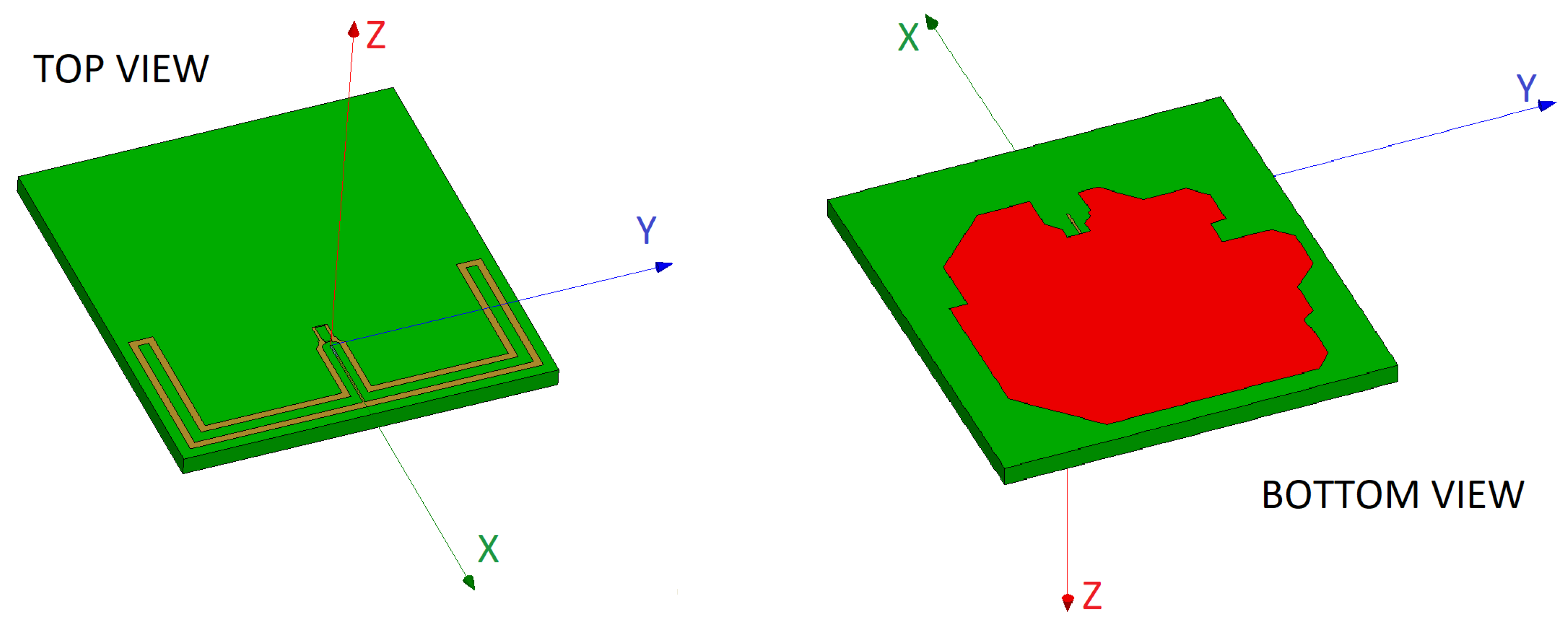
Figure 2.
Layout of the selected antennas.

Figure 3.
(a) Interior of the anechoic chamber with the Tx in the background; (b) Interior of the anechoic chamber with the Rx in the background; (c) Scheme of the arrangement of the Tx and Rx devices inside the anechoic chamber and definition of the measurement planes; (d) Distribution of angles for the measurements in elevation and azimuth planes inside the anechoic chamber.

Figure 4.
Non-conductive PVC support for anechoic chamber measurements.

Figure 5.
(a) Impedance network and balun for P1 prototypes; (b) Example of implementation of a prototype P1 of the MIFAm antenna; (c) Example of implementation of a prototype P2 of the OFD antenna (TOP VIEW); (d) BOTTOM VIEW.
Figure 5.
(a) Impedance network and balun for P1 prototypes; (b) Example of implementation of a prototype P1 of the MIFAm antenna; (c) Example of implementation of a prototype P2 of the OFD antenna (TOP VIEW); (d) BOTTOM VIEW.
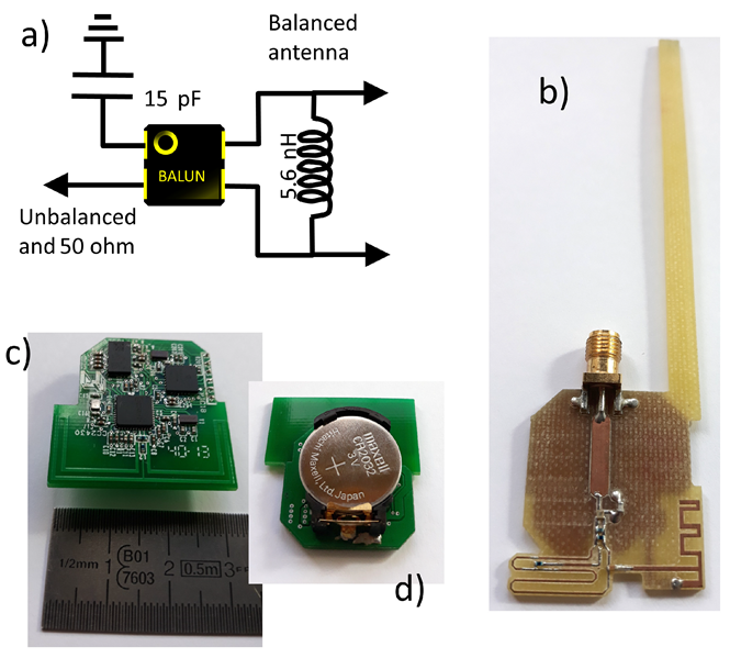
Figure 6.
Simulated return losses and radiation pattern (azimuth and elevation planes) of the proposed antennas.
Figure 6.
Simulated return losses and radiation pattern (azimuth and elevation planes) of the proposed antennas.
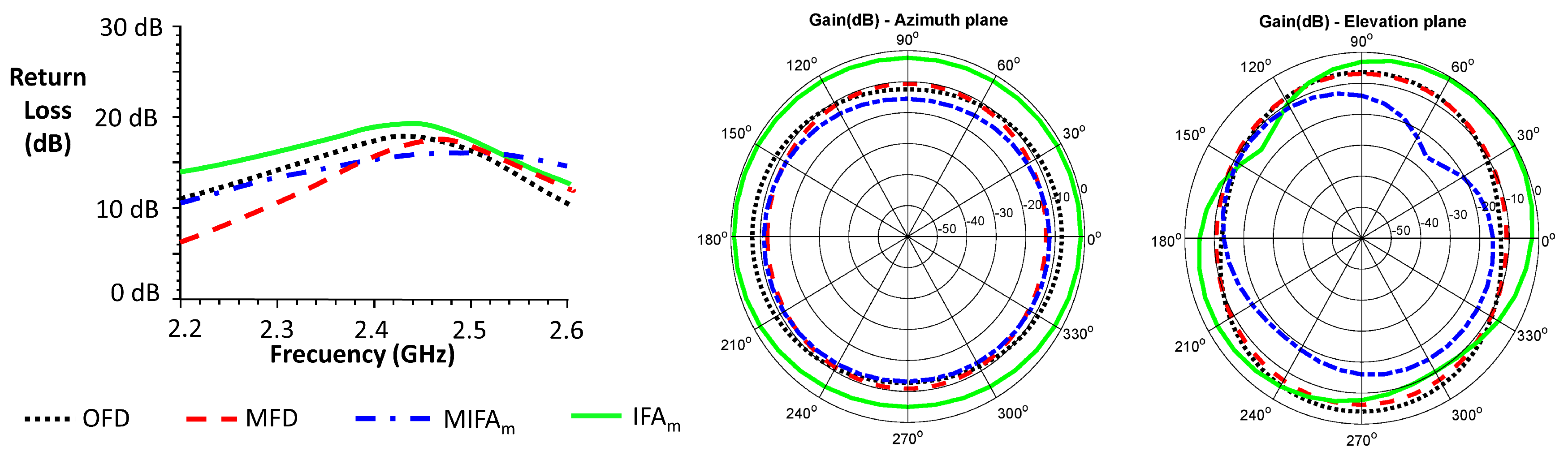
Figure 7.
Simulated and experimental radiation patterns in azimuth and elevation planes of OFD and MFD antennas.
Figure 7.
Simulated and experimental radiation patterns in azimuth and elevation planes of OFD and MFD antennas.
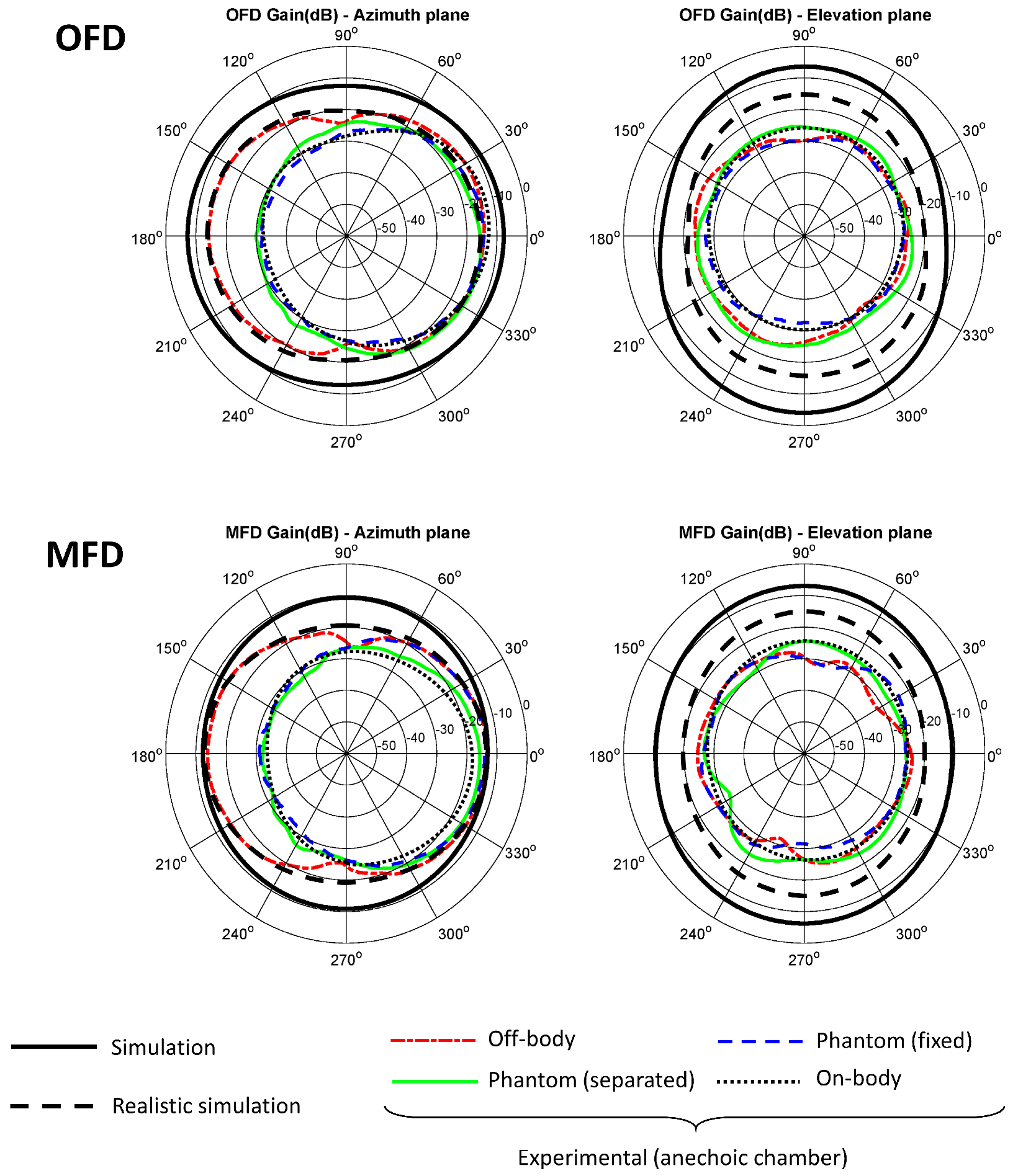
Figure 8.
Simulated and experimental radiation patterns in azimuth and elevation planes of MIFAm and IFAm antennas.
Figure 8.
Simulated and experimental radiation patterns in azimuth and elevation planes of MIFAm and IFAm antennas.

Figure 9.
Example of an antenna design employed for realistic simulations. Note: The color of the components is for visual purposes only, and not indicative of the material.
Figure 9.
Example of an antenna design employed for realistic simulations. Note: The color of the components is for visual purposes only, and not indicative of the material.

Table 1.
Antenna selection table based on compliance with design requirements.
| Antenna | Type | Resonant Frequency | Bandwidth | Gain | Omnidirectionality |
|---|---|---|---|---|---|
| Folded dipole [44] | Original | ✔ | - | - | ✔ |
| Adaptation 1 (OFD) | ✔ | ✔ | ✔ | ✔ | |
| Adaptation 2 (MFD) | ✔ | ✔ | ✔ | ✔ | |
| Adaptation 3 | ✔ | - | - | ✔ | |
| MIFA [45] | Original | - | - | - | ✔ |
| Adapted (MIFAm) | ✔ | ✔ | ✔ | ✔ | |
| IFA [46] | Original | ✔ | - | - | ✔ |
| Adapted (IFAm) | ✔ | ✔ | ✔ | ✔ | |
| [47] | Original | - | - | - | ✔ |
| Adapted | ✔ | - | - | ✔ | |
| [23] | Original | - | - | - | - |
| Original | ✔ | ✔ | - | - | |
| [48] | Original | - | - | - | - |
| Adapted | ✔ | - | - | - | |
| [49] | Original | - | - | - | - |
| Original | ✔ | - | - | - | |
| [50] | Original | ✔ | - | - | - |
| - | Adapted | ✔ | ✔ | - | ✔ |
| [51] | Original | ✔ | - | - | - |
| Adapted | ✔ | - | - | ✔ | |
| Monopole 1 | Adapted | ✔ | - | - | ✔ |
| Monopole 2 | Adapted | ✔ | - | - | ✔ |
| Dipole 1 | Adapted | ✔ | - | - | ✔ |
| Dipole 2 | Adapted | ✔ | ✔ | - | ✔ |
| Dipole 3 | Adapted | ✔ | ✔ | - | ✔ |
| Circular 1 | Adapted | ✔ | - | - | ✔ |
| Circular 2 | Adapted | - | - | - | - |
| Circular 3 | Adapted | - | - | - | ✔ |
| Yagi | Adapted | ✔ | - | - | - |
© 2019 by the authors. Licensee MDPI, Basel, Switzerland. This article is an open access article distributed under the terms and conditions of the Creative Commons Attribution (CC BY) license (http://creativecommons.org/licenses/by/4.0/).
Share and Cite
MDPI and ACS Style
Naranjo-Hernández, D.; Reina-Tosina, J.; Roa, L.M. Lessons Learned about the Design and Active Characterization of On-Body Antennas in the 2.4 GHz Frequency Band. Sensors 2020, 20, 224. https://doi.org/10.3390/s20010224
AMA Style
Naranjo-Hernández D, Reina-Tosina J, Roa LM. Lessons Learned about the Design and Active Characterization of On-Body Antennas in the 2.4 GHz Frequency Band. Sensors. 2020; 20(1):224. https://doi.org/10.3390/s20010224
Chicago/Turabian StyleNaranjo-Hernández, David, Javier Reina-Tosina, and Laura M. Roa. 2020. "Lessons Learned about the Design and Active Characterization of On-Body Antennas in the 2.4 GHz Frequency Band" Sensors 20, no. 1: 224. https://doi.org/10.3390/s20010224
Note that from the first issue of 2016, this journal uses article numbers instead of page numbers. See further details here.