A New Image Registration Algorithm Based on Evidential Reasoning


1
MOE KLINNS Lab, Institute of Integrated Automation, School of Electronic and Information Engineering, Xi’an Jiaotong University, Xi’an 710049, China
2
ONERA, The French Aerospace Lab, Chemin de la Hunière, F-91761 Palaiseau, France
3
SKLSVMS, School of Aerospace, Xi’an Jiaotong University, Xi’an 710049, China
*
Author to whom correspondence should be addressed.
Sensors 2019, 19(5), 1091; https://doi.org/10.3390/s19051091
Submission received: 30 November 2018
/
Revised: 15 February 2019
/
Accepted: 26 February 2019
/
Published: 4 March 2019
(This article belongs to the Collection Multi-Sensor Information Fusion)
Abstract
:Image registration is a crucial and fundamental problem in image processing and computer vision, which aims to align two or more images of the same scene acquired from different views or at different times. In image registration, since different keypoints (e.g., corners) or similarity measures might lead to different registration results, the selection of keypoint detection algorithms or similarity measures would bring uncertainty. These different keypoint detectors or similarity measures have their own pros and cons and can be jointly used to expect a better registration result. In this paper, the uncertainty caused by the selection of keypoint detector or similarity measure is addressed using the theory of belief functions, and image information at different levels are jointly used to achieve a more accurate image registration. Experimental results and related analyses show that our proposed algorithm can achieve more precise image registration results compared to several prevailing algorithms.
1. Introduction
Image registration is a fundamental problem encountered in image processing, e.g., image fusion [1] and image change detection [2]. It refers to the alignment of two or more images of the same scene taken at different time, from different sensors, or from different viewpoints. Image registration plays an increasingly important role in applications of surveillance [3], remote-sensing [4] and medical imaging [5].
For a collection of images to be registered, one is chosen as the reference image and the others are selected as sensed images. Image registration align each sensed image to the reference image by finding the correspondence between all pixels in the image pair and estimating the spatial transformation from the sensed image to the reference image. In this paper, we just consider the image registration between two images, i.e., there is only one sensed image together with a given reference image.
Current image registration techniques that based on image domain can be generally divided into two categories [6]: the sparse methods and dense methods. There are also some methods based on transform domain, like Fourier-Mellin transformation method [7]. The transform domain based methods are often used for image registration with similarity transformation model. In this paper, we focus on the image domain based methods.
The sparse methods [8] extracts and matches salient features from the reference image and sensed image and then estimates the spatial transformation between the two images based on these matched features. Line features (e.g., edges) and point features (corners, line intersections and gravities of regions) all can be used for image registration. Corner features are the mostly used features and can be manually selected or automatically detected by Harris [9], FAST (Features from Accelerated Segment Test) [10], SIFT (Scale-Invariant Feature Transform) [11], SURF (Speeded-Up Robust Features) [12], DAISY [13], ORB (Oriented FAST and Rotated BRIEF) [14], KAZE [15], etc.
In contrast to the sparse methods, the dense methods [16] do not detect features from the image pair but search the optimal spatial transformation directly that can best match all the pixels in the image pair. Similarity (resp. dissimilarity) measures are defined to quantify the independency (resp. dependency) between the pair of images. Various similarity and dissimilarity measures have been proposed [17] such as RMSE (Root-Mean-Squared Error), PSNR (Peak Signal to Noise Ratio), Spearman’s Rho [18], NCC (Normalized Cross-correlation Coefficient) and MI (Mutual Information). It should be noted that dense methods based on RMSE or PSNR cannot handle the cases with illumination variation since these two similarity/dissmilarity measures are very sensitive to illumination changes.
Both the sparse methods and dense methods involve uncertainty problems. For the sparse methods, keypoints obtained from different keypoint detectors describe different corner features of the image. Therefore, image registrations based on different keypoint detectors would obtain different spatial transformations. For the dense methods, different similarity (dissimilarity) measures quantify the difference between the pair of images from different aspects so that image registrations based on different similarity (dissimilarity) measures would obtain different spatial transformations. These different spatial transformations obtained have their own pros and cons, and the selection of the spatial transformation (the selection of the feature detector or similarity measure indeed) would bring uncertainty.
To deal with the uncertainty caused by the particular selection of feature detector or similarity (dissimilarity) measure, one feasible way is to combine these registration transformations obtained from different feature detection methods or similarity measures to obtain a better registration result. The belief functions introduced in Demspter–Shafer Theory (DST) [19] of evidence offer a powerful theoretical tool for uncertainty modeling and reasoning; therefore, we propose a fusion based image registration method using belief functions. In this paper, the spatial transformations obtained from different feature detection algorithms or similarity measures compose the frame of discernment (FOD) and their uncertainties are modeled using belief functions. In uncertainty modeling, image information at different levels, i.e., image’s intensities, edges and phase angles, are jointly used to evaluate the beliefs about image transformations. Then, these uncertainties are further handled through the evidence combination of the above multiple information. The final registration result is obtained according to the combined evidence.
This paper is an extension of our previous work in [20] where the basic idea is briefly presented. The main added values with respect to [20] are as follows. First, the transformation model between the reference image and sensed image is more comprehensive. We use similarity transformation model in [20] but use projective transformation model in this paper, which is more general since all similarity transformations are examples of projective transformations. Second, the keypoints used in the sparse approach in [20] are manually selected. To reduce the subjective influence to the registration result, in this paper, the keypoints are generated from detection algorithms. Accordingly, feature matching and mismatching removal are added after the keypoint detection. Third, when modeling uncertainties, one more information source, i.e., image’s phase angle information, is considered in this work. Fourth, more experiments and analyses are provided for performance evaluation and analysis.
The rest of this paper is organized as follows. The basics of image registration are introduced in Section 2. The basics of evidence theory are introduced in Section 4. The proposed image registration method is introduced in Section 4.1 with emphasis of uncertainty modeling and handling. Evaluation method is introduced in Section 5. Experiment results of the proposed method and other registration methods are presented and compared in Section 6.1. Concluding remarks are given in Section 7.
2. Basics of Image Registration
For two (or more) images of the same scene taken at different time, from different sensors, or from different viewpoints, one is chosen as the reference image (R) and the other one is chosen as the sensed image (S). In this paper, we focus on the projective transformation model between the reference image and sensed image, which is a commonly used model in image registration [16].
Denote pixel coordinates in the reference image R as and their mapping counterparts in the sensed image S as . The projective transformation from R to S can be expressed based on the homogeneous coordinates (Homogeneous coordinates can easily express the translation transformation as matrix multiplications while Cartesian coordinates cannot) as
The similarity transformation and affine transformation are important specializations of the projective transformation, as illustrated in Table 1.
The purpose of image registration is to estimate the transformation T to align the sensed image S with the reference image R by
where and denote pixel coordinates in registered sensed image and sensed image S, respectively. Current image registration techniques can be divided into two categories [6] in general, including the sparse method and dense method. Basics of these two methods are introduced below.
2.1. Sparse Image Registration and Its Uncertainty
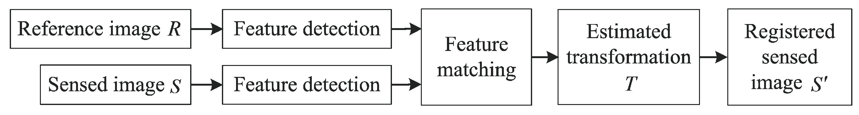
The feature detection and feature matching are two critical steps in the sparse methods. The flow chart of the sparse approach is illustrated in Figure 1, where each functional block is detailed in the sequel.
2.1.1. Feature Detection
Corner features are the mostly used features in image registration due to their invariance to imaging geometry [6]. Some early keypoint detectors, like Harris and FAST, are very sensitive to image scale changes so that have poor performance when the sensed images have different scales with the reference image. The most well-known SIFT detector shows good robustness to illumination, orientation and scale changes. Most scale invariant detectors, like SIFT, SURF, ORB and BRISK, detect and describe features at different scale levels by building or approximating the Gaussian scale space of the image. In a different way, KAZE detects features in a nonlinear scale space built using efficient additive operator splitting techniques and variable conductance diffusion.
2.1.2. Feature Matching
To align the sensed image and the reference image, the detected keypoints in the two images are matched first by comparing their local feature characterized by descriptors. Generally, if the two keypoints’ descriptors are similar, the two keypoints are likely to be a matched pair. Given a keypoint t in the reference image, there might be a set of candidates in the sensed image having similar descriptor with t. Among these candidates, t’s real counterpart should have the closest distance with t, and at the same time its distance should be much closer than other candidates’ distances.
The accuracy of the keypoints’ matching affects the accuracy of the transformation’s estimation. The mismatched keypoint pairs should be further removed before estimating the transformation. RANSAC (RANdom SAmple Consensus) [21] and MSAC (M-estimator SAmple and Consensus) [22] are often used to deal with this problem. A recent RANRESAC (RANdom RESAmple Consensus) [23] algorithm has been proposed to remove mismatched keypoint pairs for noisy image registration. Besides the accuracy of the keypoints’ matching, the distribution of matched pairs over the image space is another key factor to obtain a high-quality estimation of transformation.
2.1.3. Transformation Estimation
With all the matched keypoint pairs, the transformation matrix T can be estimated using Equation (1). Since T has eight degrees of freedom, four point correspondences (with no three collinear) are needed to obtain the unique solution of T according to Cramer’s rule.
Normally, the amount of the matched keypoint pairs is more than four and T can be estimated using the least squares (LS) fitting technique [6] by searching the minimum sum of the Euclidean distances between all the matched keypoints:
where represents the coordinate of the ith matched keypoint in the reference image and represents the coordinate of the ith matched keypoint in the registered sensed image transformed from the sensed image using Equation (2).
2.1.4. Uncertainty Encountered in Sparse Approach
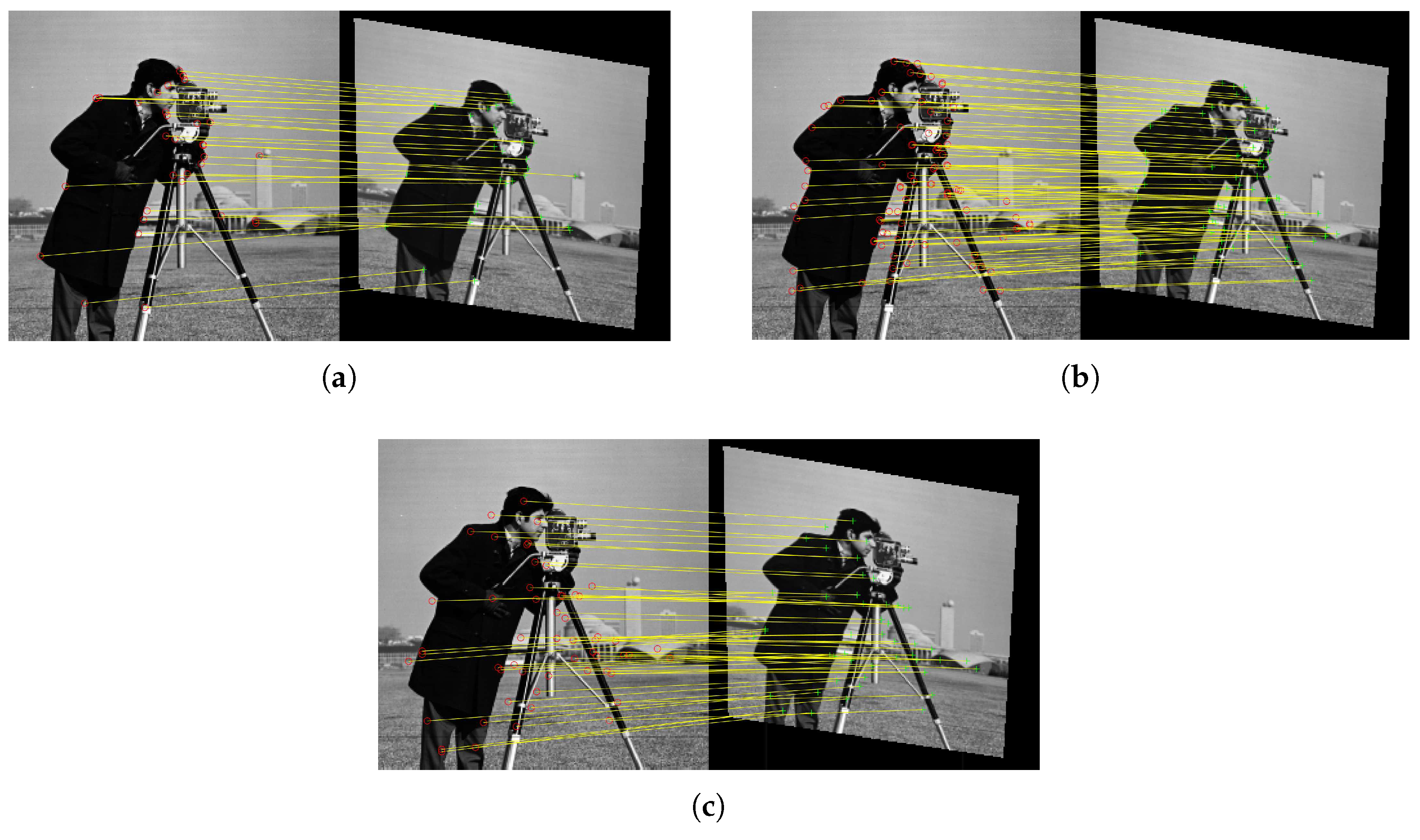
Since different keypoint detection algorithms detect different kinds of corner features, the detected keypoints are usually different, as shown in Figure 2.
Image registrations based on different matched keypoint pairs would in general yield different spatial transformations to align two images. Different transformations obtained have their own pros and cons. Therefore, the selection of keypoint detection algorithms would bring uncertainty problem to the registration results.
2.2. Dense Image Registration and Its Uncertainty
The dense image registration estimates the optimal transformation T by searching the largest similarity (or the smallest dissimilarity) between the reference image R and the registered sensed image :
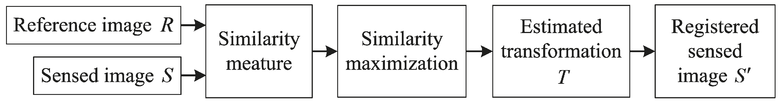
where is a chosen similarity measure. The flow chart of the dense approach is illustrated in Figure 3, where each functional block is detailed in the sequel.
2.2.1. Similarity Measure
Various similarity (or dissimilarity) measures have been proposed. Here we briefly introduce the commonly used MI, NCC and PSNR measures.
(1) MI
MI measure between images A and B is
where is the joint probability distribution function (PDF) of images A and B, and and are the marginal PDFs of A and B, respectively. MI is larger when A and B are more similar.
(2) NCC
For given images A and B with size of , NCC measure between them is
where and are the pixels’ intensities in images A and B at , respectively; and are the mean intensities of A and B, respectively; and are the standard deviation intensities of A and B, respectively. NCC is larger when A and B are more similar.
(3) PSNR
PSNR measure between images A and B is
where MSE. PSNR is larger when A and B are more similar. Since PSNR measure is very sensitive to illumination changes, it cannot be used for image registration when there are illumination variations between image pairs.
2.2.2. Transformation Estimation
The estimation for transformation T, i.e., Equation (4), is always a non-convex problem and is not so easy to obtain the global maximum [24]. Therefore, advanced optimization methods [25], or intelligent optimization approaches (like genetic, or particle swarm algorithms, etc.) are often used to estimate the optimal transformation T.
2.2.3. Uncertainty Encountered in Dense Approach
Since different similarity (dissimilarity) measures compare two images from different aspects, their calculated similarities (dissimilarities) between the reference image and registered sensed image are different. Image registration based on different measures would obtain different spatial transformations to align two images and they have their own pros and cons. Therefore, the selection of similarity (dissimilarity) measure would bring uncertainty problem to the registration results.
To deal with the uncertainty caused by the selection of feature detection algorithms or similarity measures, one feasible way is to combine the registration transformations (, , …, ) obtained from different feature detection algorithms (or different similarity measures) to expect a better registration result. We propose an evidential reasoning [19] based image registration algorithm to generate a combined transformation from , , …, thanks to the ability of belief functions for uncertainty modeling and reasoning. Basics of the theory of belief functions are recalled first below.
3. Basics of Evidence Theory
Dempster–Shafer evidence theory (DST) [19] is a theoretical framework for uncertainty modeling and reasoning. In DST, elements in the frame of discernment (FOD) are mutually exclusive and exhaustive. The power set of , i.e., , is the set of all subsets of . For example, if , then . The basic belief assignment (BBA, also called mass function) is defined by a function m: , satisfying
where depicts the evidence support to the proposition A. A is called a focal element when . If there is only one element in A, like and , A is called the singleton element; if there are more than one element in A, e.g., and , A is called the compound element. The belief assigned to a compound element represents the degree of ambiguity for the multiple elements.
The plausibility function () and belief function () are defined as follows:
Dempster’s combination rule [19] for combining two distinct pieces of evidence is defined as
Here, denotes the total conflict or contradictory mass assignments.
An alternative fusion rule PCR6 [26] for the combination of two sources is defined as
where is the conjunctive rule defined as
General PCR6 formula for the combination of more than two sources is given in [26].
For a probabilistic decision-making, Smets defined the pignistic probability transformation [27] to obtain the probability measure from a BBA
where is the cardinality of A. The decision can be made by choosing the element in FOD whose value is the highest one and higher than a preset threshold. Other types of probability transformation methods can be found in [26,28].
4. Image Registration Based on Evidential Reasoning
To deal with the uncertainty caused by the choice of keypoint detectors in the sparse approach or the choice of similarity measure in the dense approach, we propose an image registration method based on evidential reasoning. Suppose that the spatial transformation between the reference image and sensed image is projective. Our purpose is to estimate the transformation matrix to align two images. Unlike the prevailing methods estimating the transformation matrix from single method of keypoint detection or similarity (dissimilarity) measure, we estimate the transformation matrix by jointly utilizing different keypoint detection methods or similarity measures.
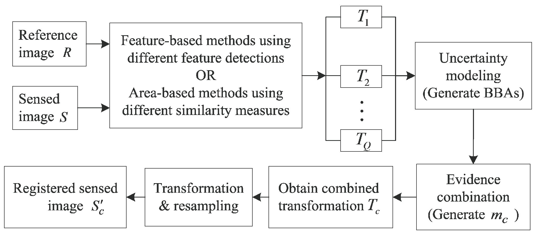
To use belief functions for image registration, one should define the frame of discernment (FOD) first. The FOD , where Q is the amount of transformations obtained from different single feature detection algorithms or different single similarity measures. We first model the beliefs for every proposition using BBAs. A can be single transformation in FOD or a set of transformations in FOD. One BBA depicts the support to each proposition A from one evidence source. The BBA allocations from different evidence sources describes the uncertainty of the transformations in FOD. Next, the BBAs are combined to generate the combined BBA depicting the fused support to each proposition A. Then, the combined transformation is generated from the combined BBA . Finally, the registered sensed image is transformed from the sensed image using Equation (2). During this process, the resampling [29] is needed to determine the intensity of each pixel in . Figure 4 illustrates the flow chart of this new proposed method. It should be noted that the classical interpretation of BFT assumes that the final estimation should be in the FOD. In this work, we relax this assumption and the final transformation is a combination result of those in the FOD.
4.1. Uncertainty Modeling
If the similarity between the reference image R and registered sensed image is large, the corresponding transformation is quite accurate and should be allocated large support ( is transformed from sensed image S by ). Here we use NCC (Other similarity or dissimilarity measures, e.g., MI, are also appropriate to quantify the similarity here) to measure the similarity between R and :
where and are the mean intensities of R and , respectively; and are the standard deviation intensities of R and , respectively.
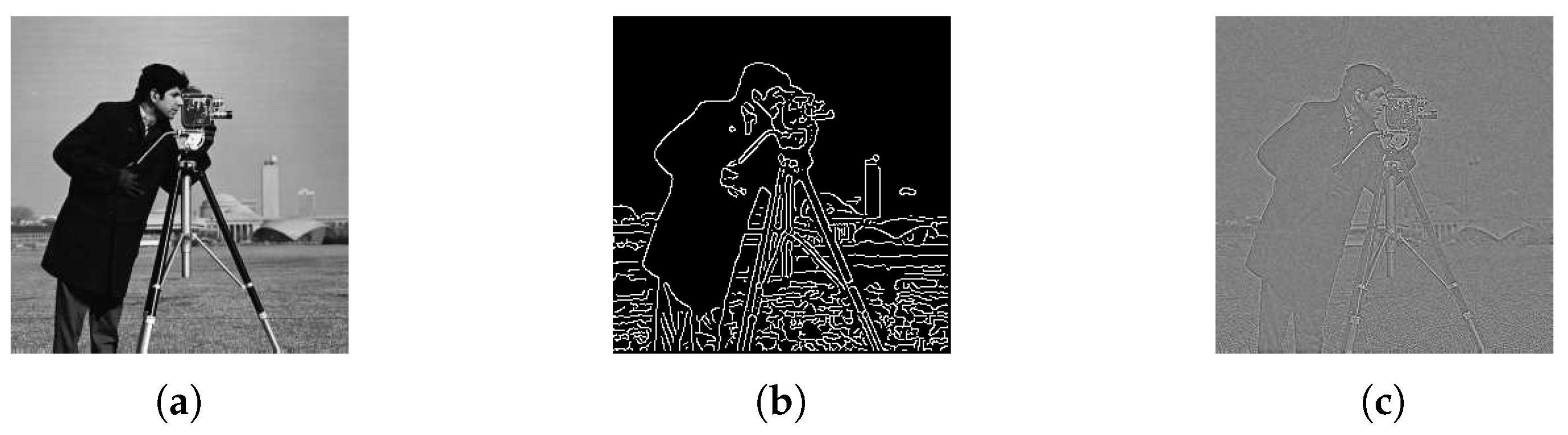
Since multi-source information can help to reduce the uncertainty through evidence combination, we use different levels of image information to quantify the similarity between R and . The similarity can be calculated from the gray images, edge feature images or reconstructed images using phase angle as shown in Figure 5. Their corresponding are denoted as , and , respectively. The edge detection method used in Figure 5b is the Canny detector [30]. More details of the image reconstruction from phase angle information can be found in [29].
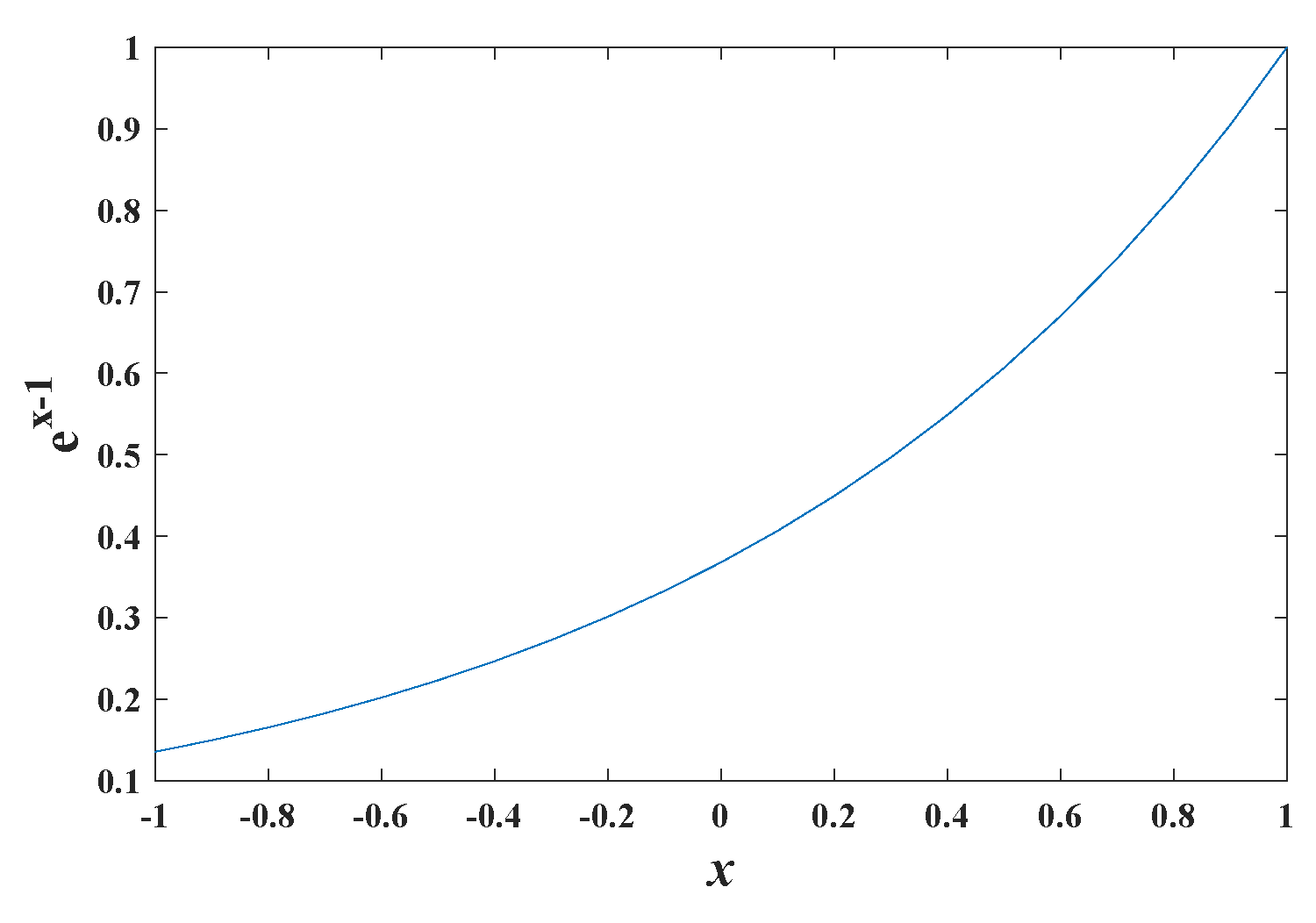
The value range of is . According to our experiments, most values of are larger than 0. Before allocating BBAs, we first enlarge the differences of within using function , as illustrated in Figure 6.
Each level of image information (gray images (G), edge feature images (E) and reconstructed images using phase angle (P)) can be viewed as one evidence source and their corresponding can be used to assign beliefs for transformation :
4.2. Fusion-Based Registration
After obtaining BBAs , and , we generate the combined BBA using a combination rule denoted symbolically with ⊕:
describes the combined evidence support to (a matrix with 6 unknown parameters). The combined transformation is computed by
Finally, the registered sensed image can be obtained using Equation (2) following the resampling.
5. Evaluation of Image Registration
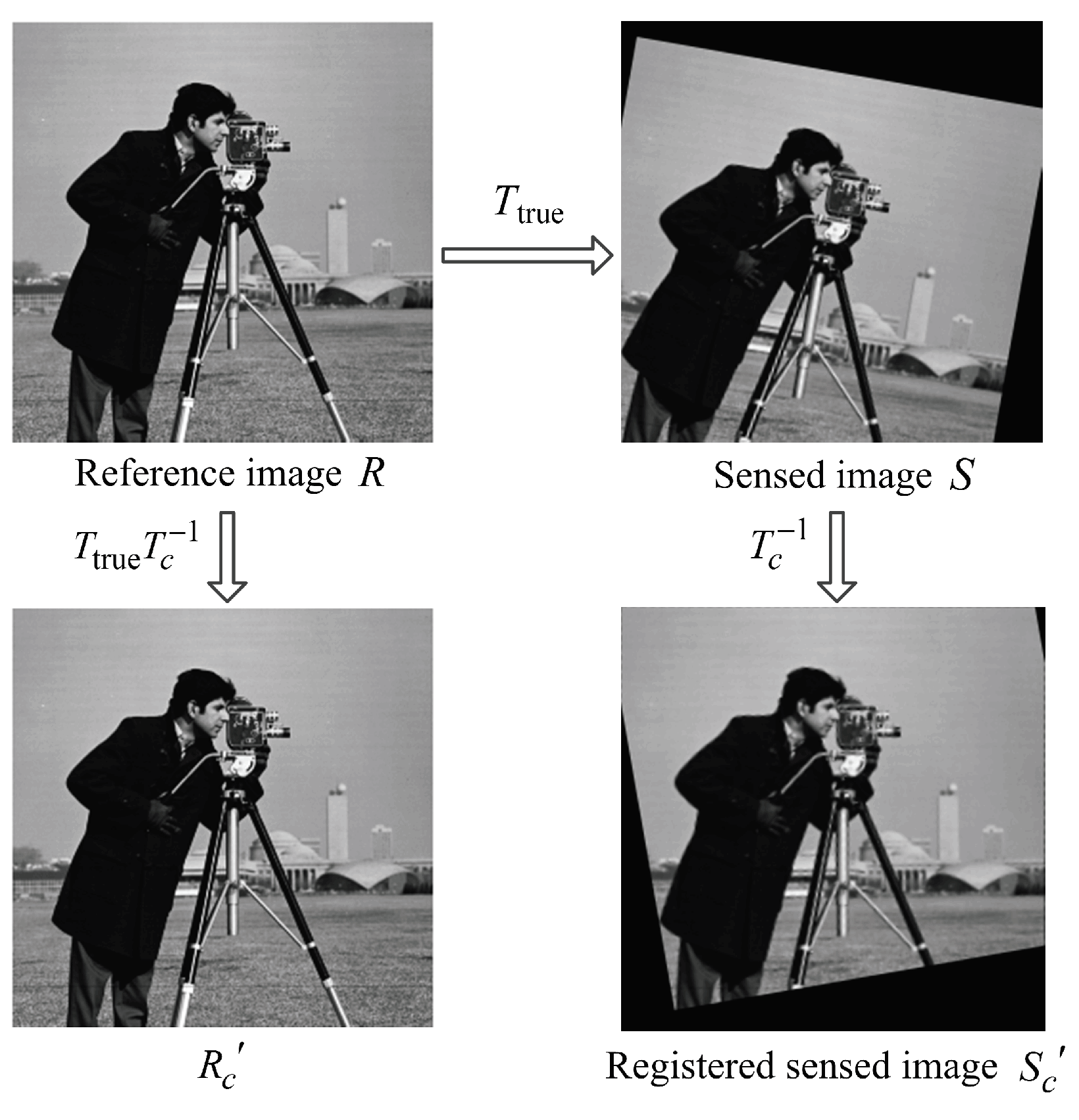
Since the purpose of image registration is to align the reference image R and sensed image S to a single coordinate frame, one popular evaluation method for the registration result is to quantify the difference (usually quantified by Root-Mean-Squared Error (RMSE)) between R and the registered sensed image [31,32]. However, since is transformed from the sensed image S, which may have less information than R (S may be part of R or have lower resolution than R since R and S can be taken from different views or taken by different cameras), the difference between R and could be large even when the estimated transformation equals to the true transformation from the reference image R to the sensed image S, as shown in Figure 7. Therefore, this kind of evaluation method is not accurate enough.
Another popular evaluation method is to quantify the difference between the reference image R and image , which is transformed from R by the transformation matrix [16,33], as shown in Figure 7. The mapping relationship between pixel at in image R and pixel at in image satisfies
when the registration is absolutely accurate, and .
In this paper, we evaluate the registration performance by quantifying the difference between R and using AAID (average absolute intensity difference) [16]:
AAID is smaller when the registration result is better.
6. Experiments
To verify the performance of our new proposed image registration method, we provide experiments on noise-free images and noisy images, respectively. Image registration under the noisy condition is difficult since the noise pixels bring difficulties for keypoints’ detection and matching and reduce the accuracy for similarity measure. For the sparse method, experiment results based on BRISK [34], KAZE [15] and SURF [12] feature detection algorithms are provided for comparison. For the dense method, experiment results based on MI, PSNR and NCC similarity measures are provided for comparison. For the noisy image registration, the experiment result of RANRESAC (a recently proposed method for noisy image registration) [23] is also provided for comparison.
6.1. Sparse Image Registration Results
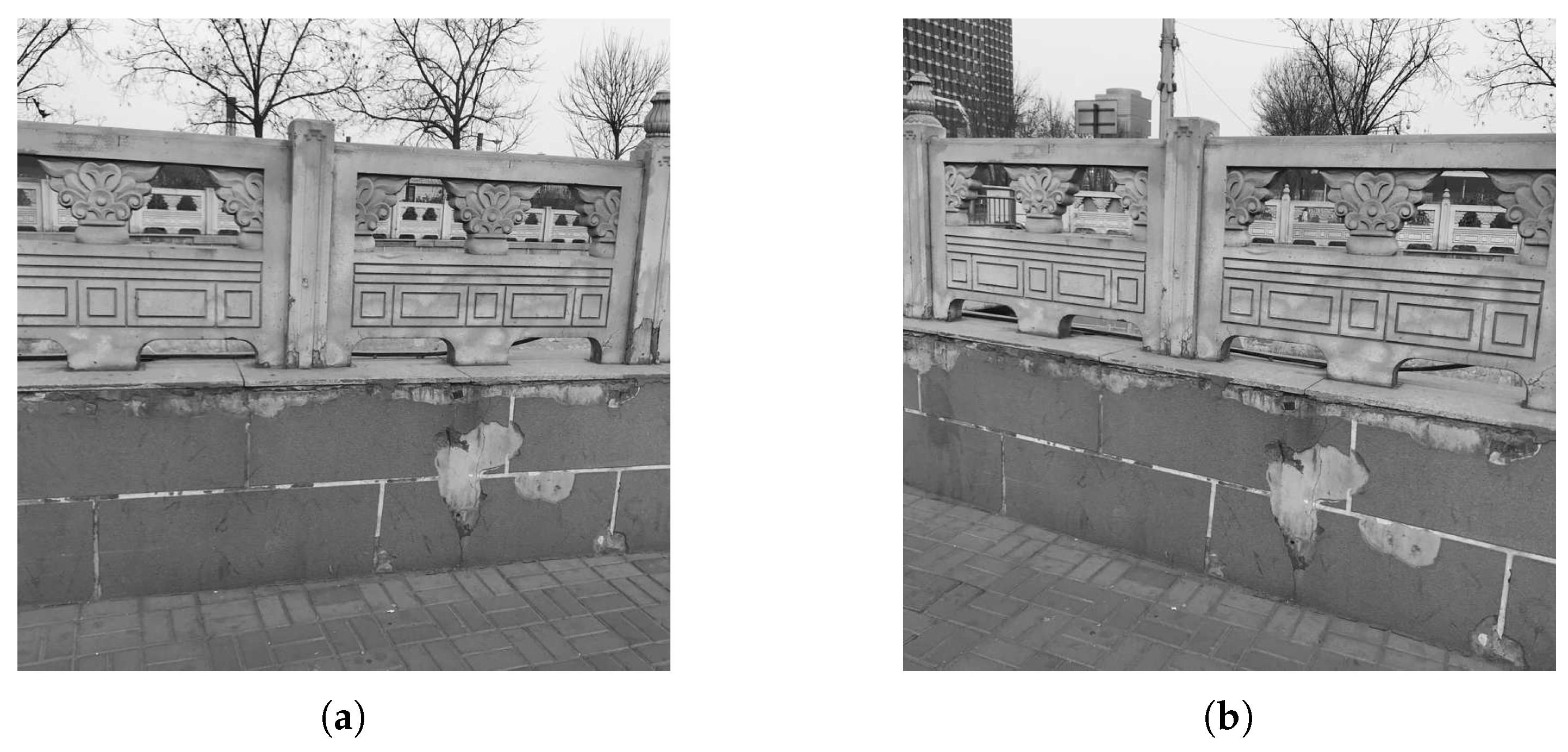
We first do experiments on actual data to illustrate the effectiveness of the proposed method. The reference image and sensed image are taken from different cameras with different views, as shown in Figure 8. BRISK, KAZE and SURF feature detections are used for generating transformations , and , respectively. When deriving combined BBAs in Equation (17), an alternative fusion rule PCR6, which is more robust than Dempster’s rule [26], is also used for comparison.
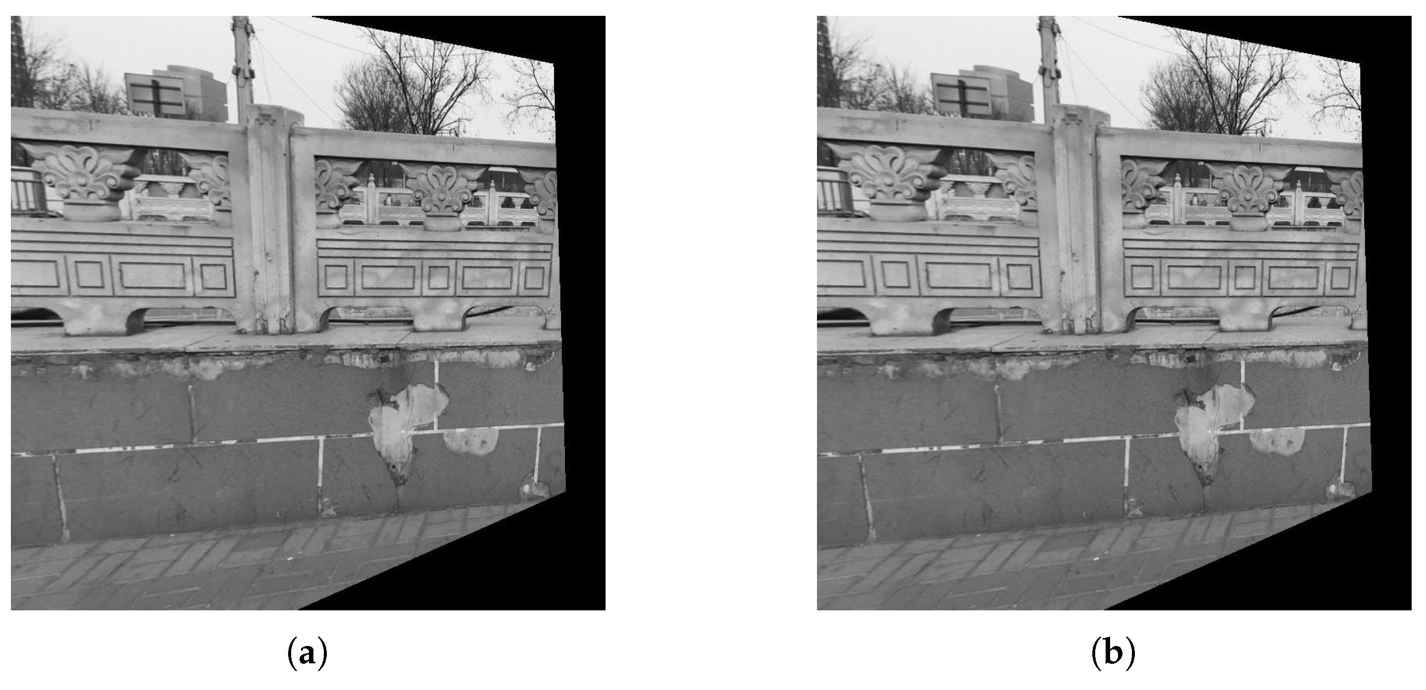
The registered results of the proposed method are illustrated in Figure 9. From Figure 9, the proposed method can successfully align the sensed image to the reference image illustrating that the proposed method is effective for actual data.
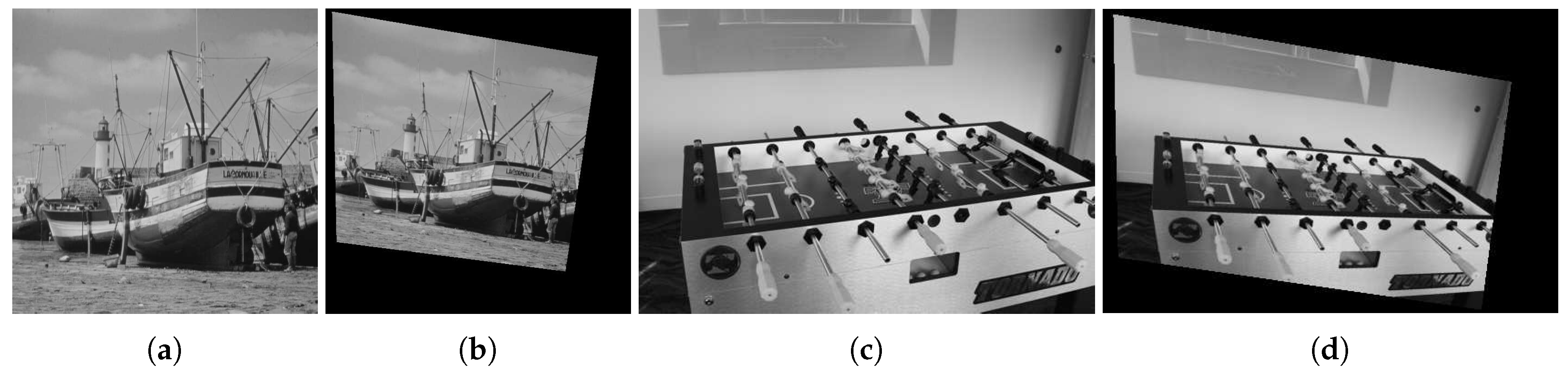
To quantify the accuracy of the registration results, the actual transformation between the reference image and sensed image is needed and we do experiments on simulated images. We first do experiments on Boats image (The reference image can be found at https://imagej.nih.gov/ij/images/boats.gif.) and Foosball image (sample image from the MATLAB), as shown in Figure 10.
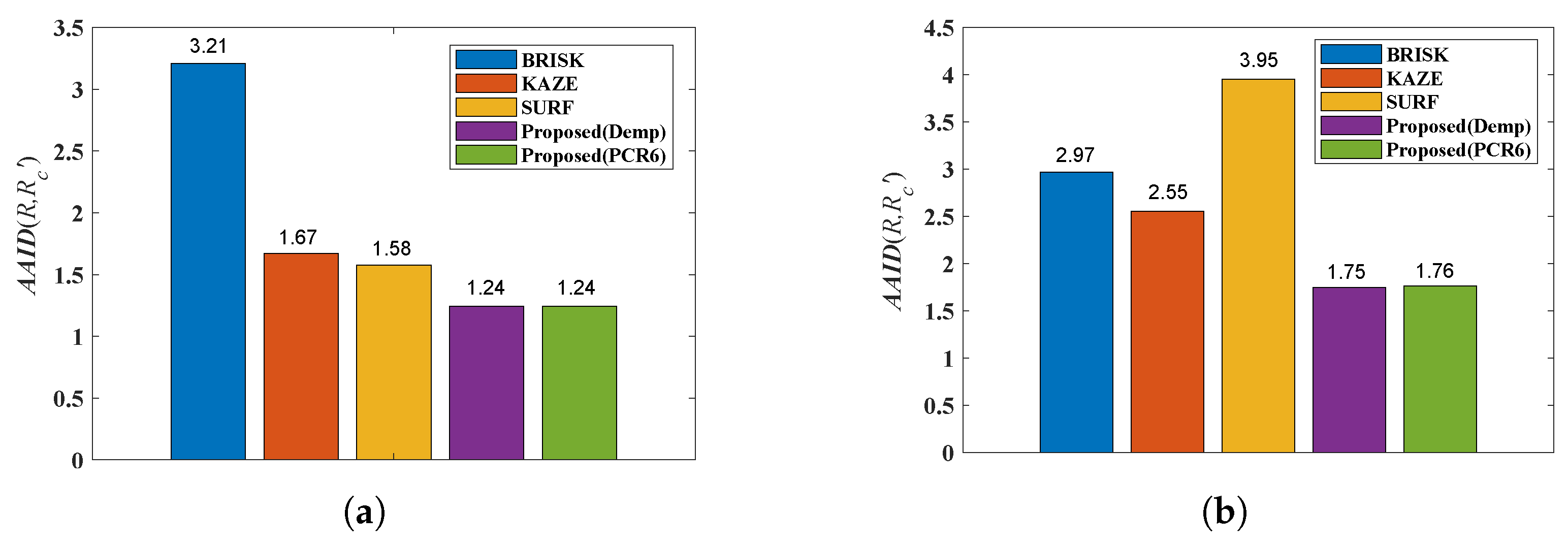
The AAID evaluations of these registration results for Boats image and Foosball image are compared in Figure 11, where Demp represents the Dempster’s combination rule. According to Figure 11, the proposed fusion-based method achieves much better registration result (smaller AAID) than algorithms based on BRISK, KAZE or SURF feature detections, respectively.
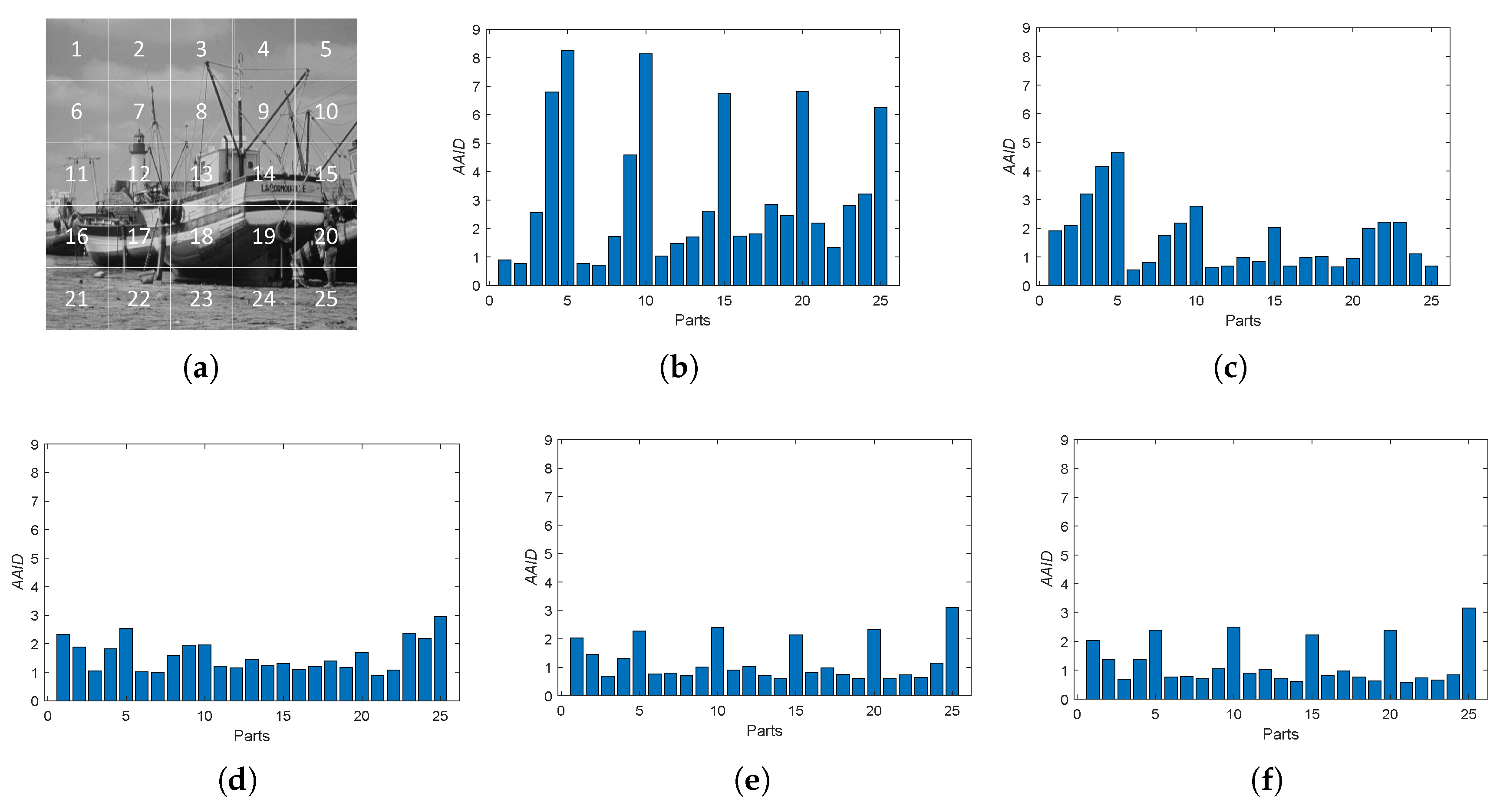
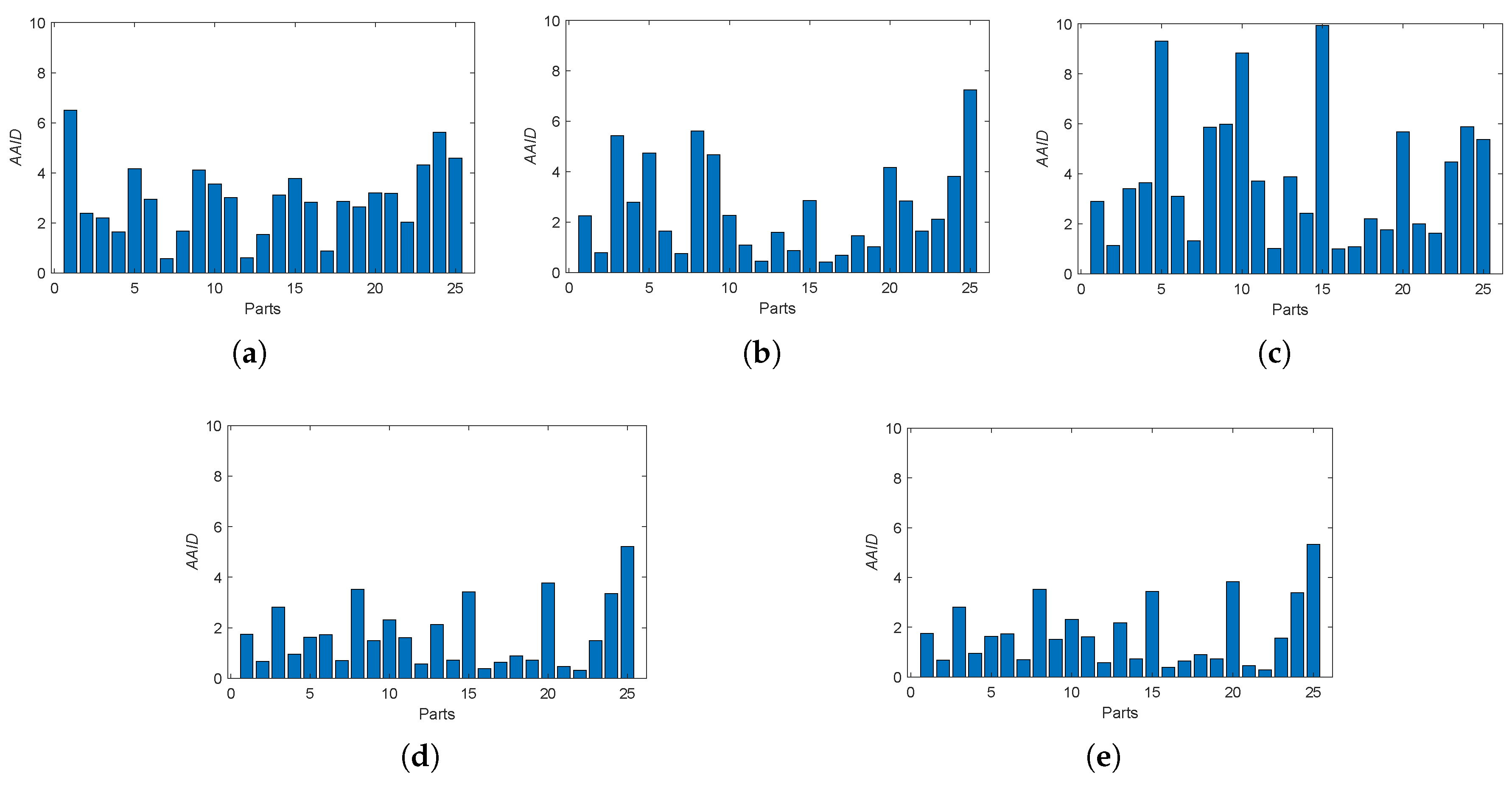
Furthermore, we also analyzed the spatial partition of the AAID evaluation for each result by evenly dividing the reference image into parts (as shown in Figure 12a) and calculating the AAID between the reference image and the registration result in each part. The AAID spatial partition results for Boats image and Foosball image are illustrated in Figure 12 and Figure 13, respectively. For Boats image, the AAID of BRISK and KAZE results varies significantly for different parts while the SURF result is relatively uniform; the proposed methods have low and similar AAID in most parts while the rightmost parts (parts 5, 10, 15, 20 and 25) have significant larger AAID. For Foosball image, the AAID spatial partition of all these results are uneven.
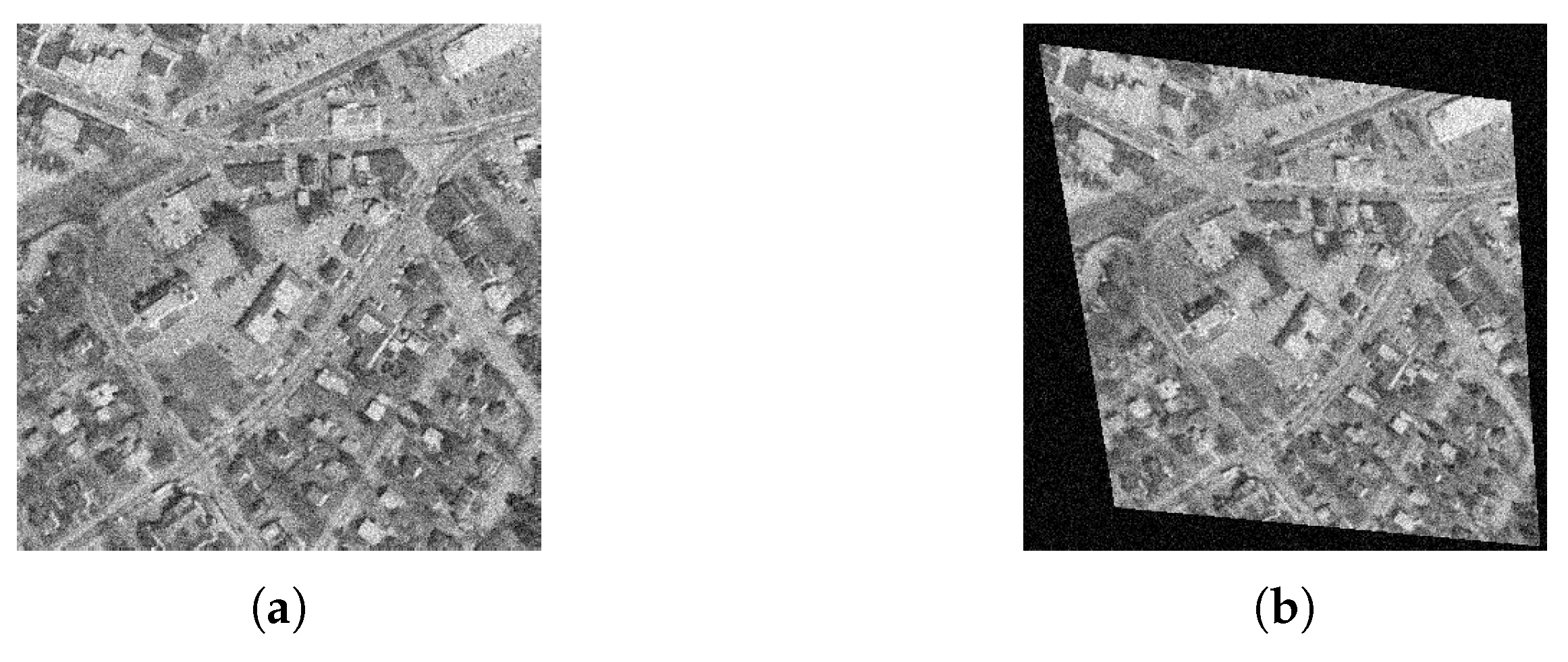
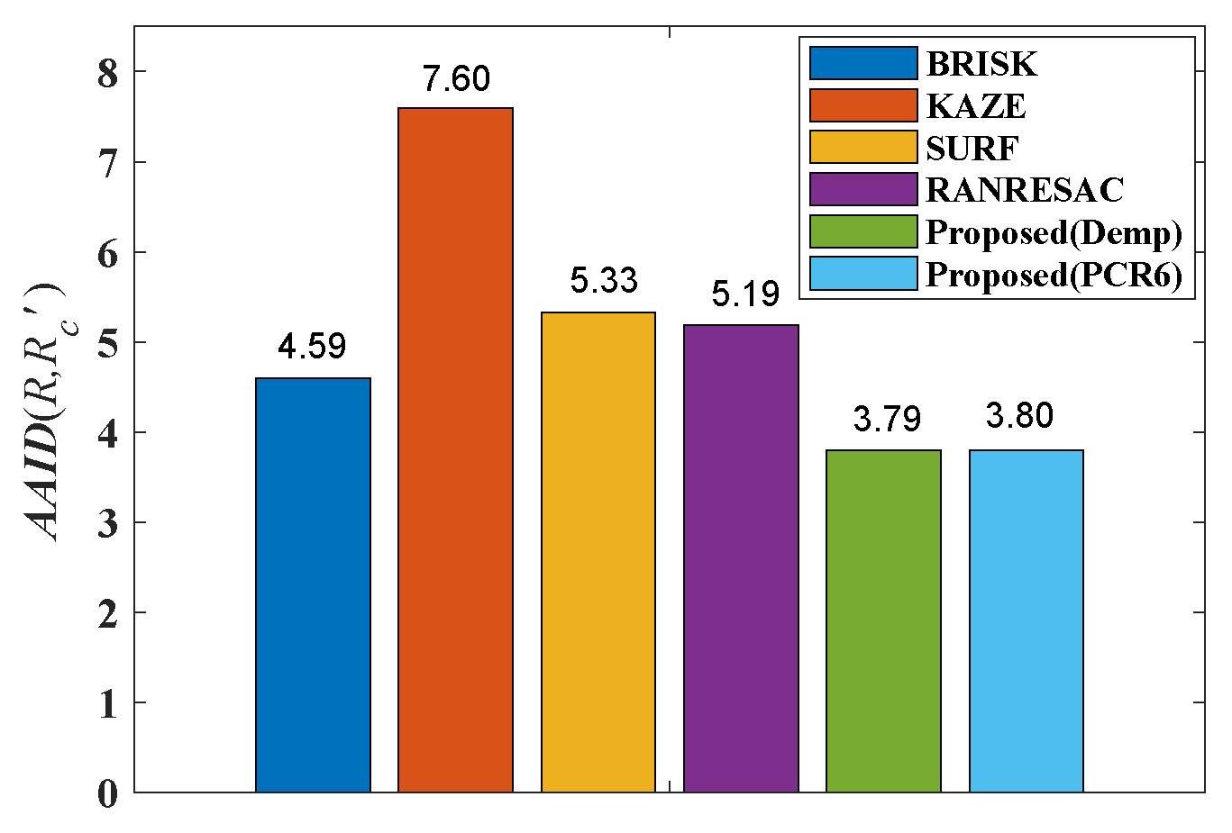
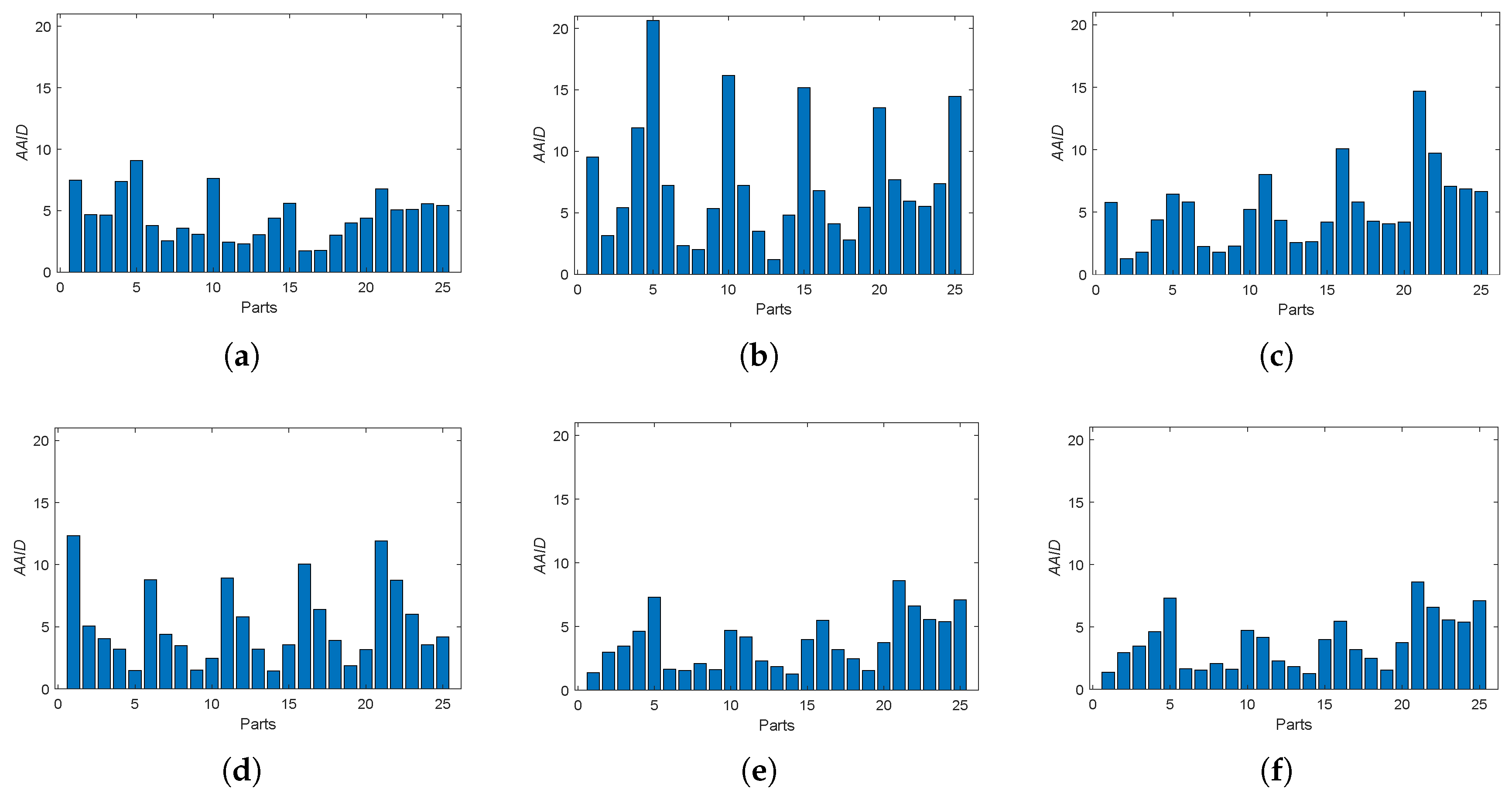
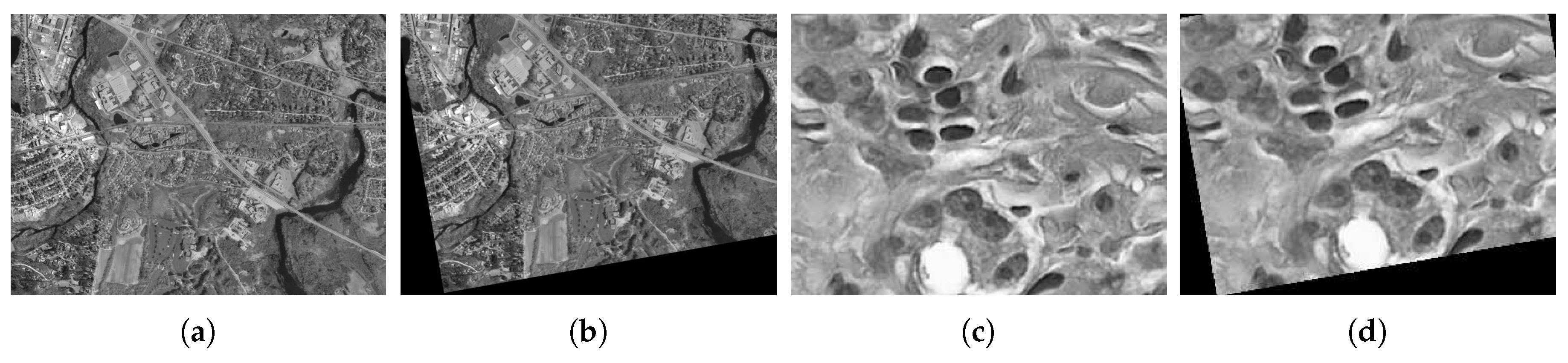
Then, we consider the noisy image registration and do experiments on West Concord image pair (sample image from the MATLAB) with zero-mean Gaussian noise (variance is 0.01), as shown in Figure 14. The AAID evaluations for these registration results are compared in Figure 15, where the proposed fusion-based methods achieve better performance (smaller AAID) than RANTESAC and methods based on BRISK, KAZE and SURF feature detections, respectively. The spatial partition of the AAID evaluation for each result is illustrated in Figure 16, where the KAZE result is the most uneven one.
6.2. Dense Image Registration Results
Since the optimization of dense registration is intractable when the solution space has high dimensions, we simplify the transformation model to rigid transformation here. The solution space for rigid model only has three dimensions: one for rotation and two for translations in horizontal and vertical directions, respectively. We first provide experiments on Concord image and Hestain image (sample images from the MATLAB) as shown in Figure 17, where the sensed image is transformed from the reference image through the rotation ( in anticlockwise) and translation () successively.
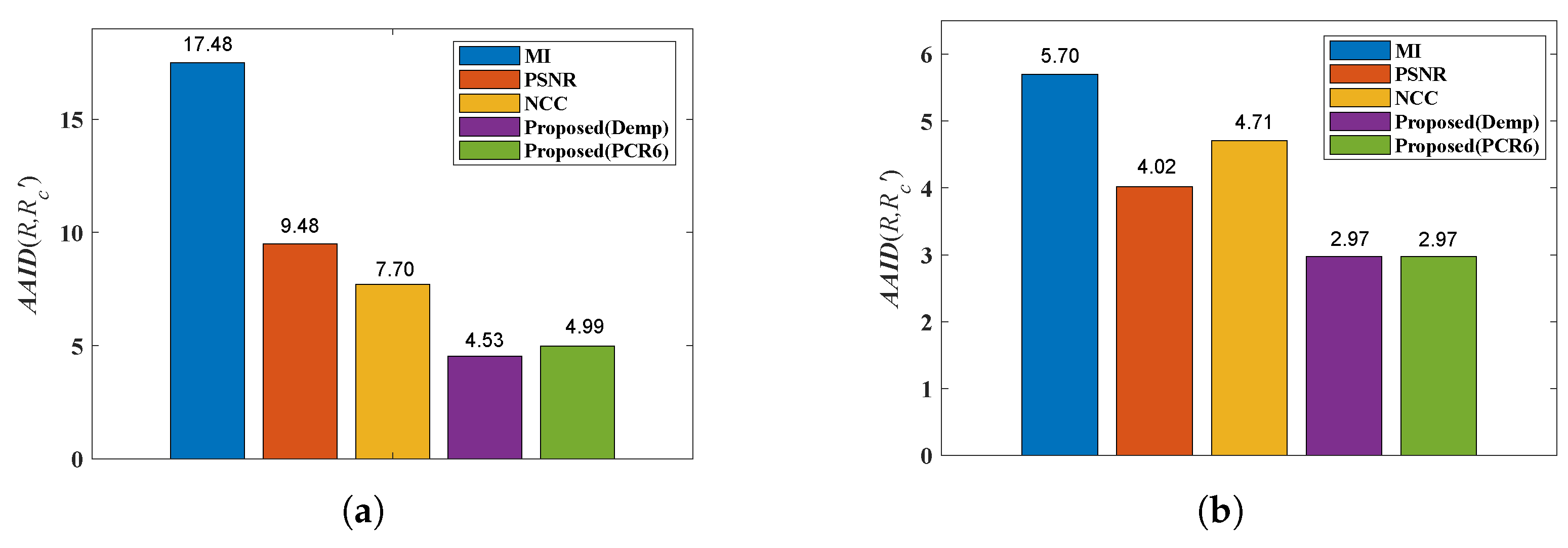
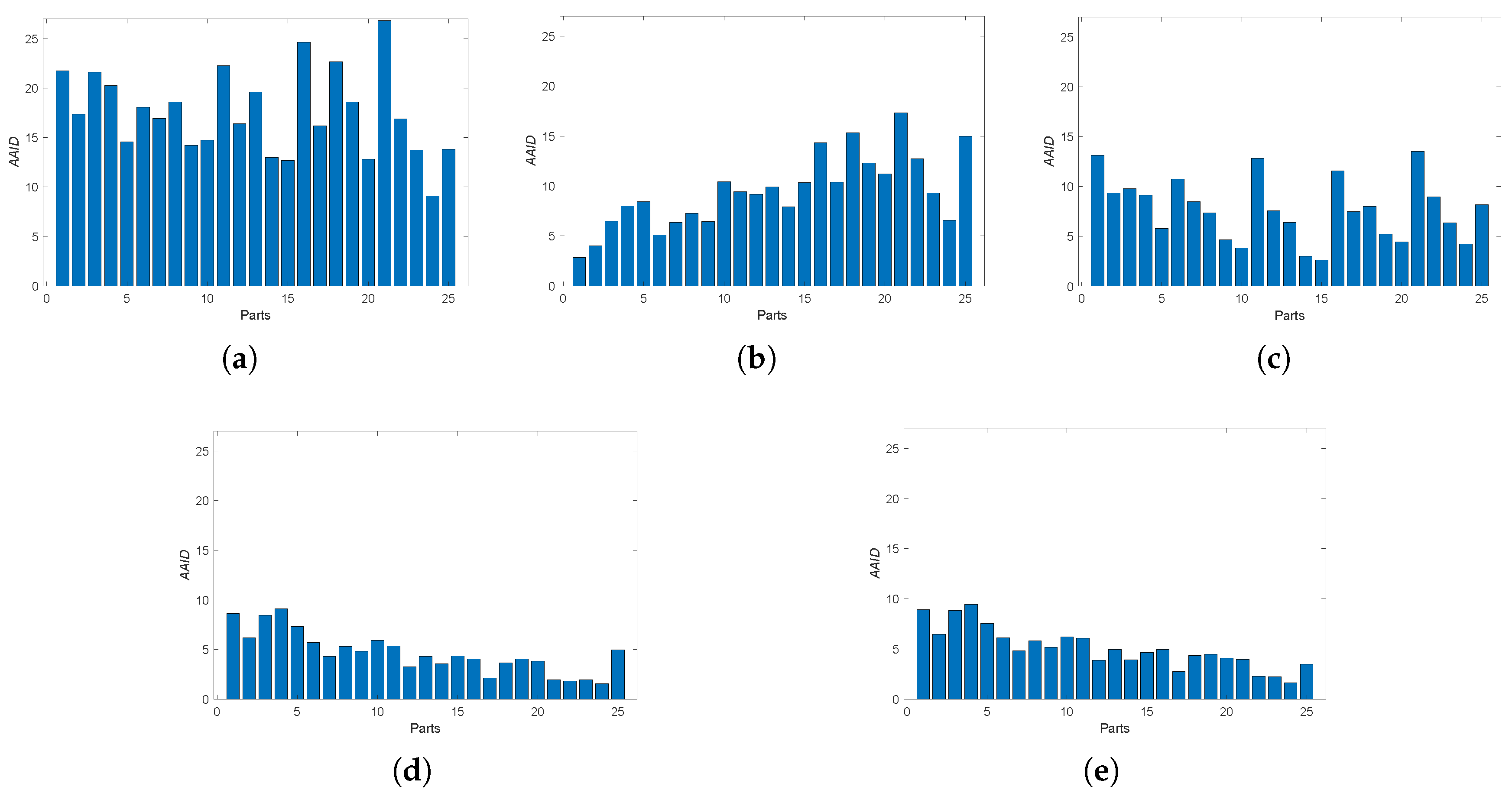
In the proposed dense approach, MI, PSNR and NCC similarity measures are used for generating transformations , and , respectively. The AAID evaluations of these registration results for the Concord image and Hestain image are compared in Figure 18, where the proposed fusion-based methods achieve much better registration results (smaller AAID) than algorithms based on MI, PSNR or NCC similarities, respectively. The AAID spatial partition results for Concord image and Hestain image are illustrated in Figure 19 and Figure 20, respectively. For these two images, the AAID results of the proposed methods are smaller in the downside parts compared with those in upside parts.
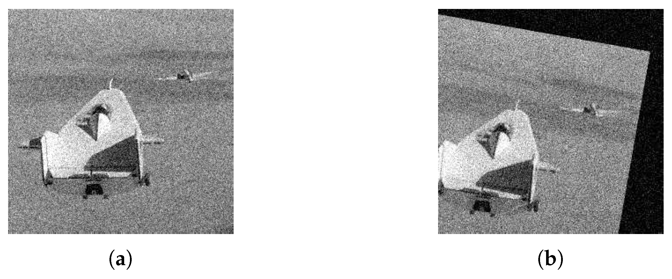
Then, we consider the noisy image condition and implement experiments on Lifting Body image pair (sample image from the MATLAB) with zero-mean Gaussian noise (variance is 0.01), as shown in Figure 21. The sensed image is transformed from the reference image through the rotation () and translation (), successively.
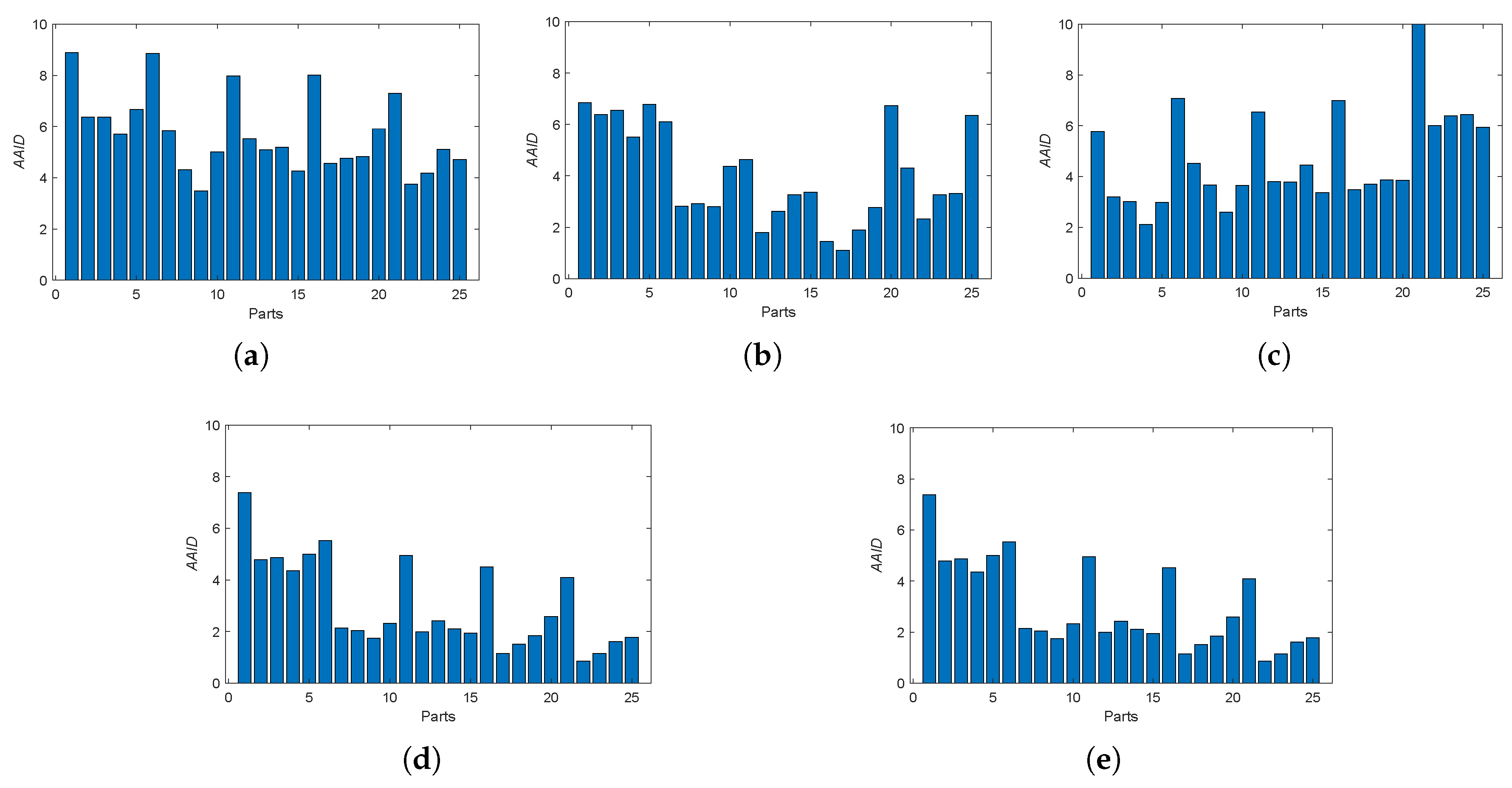
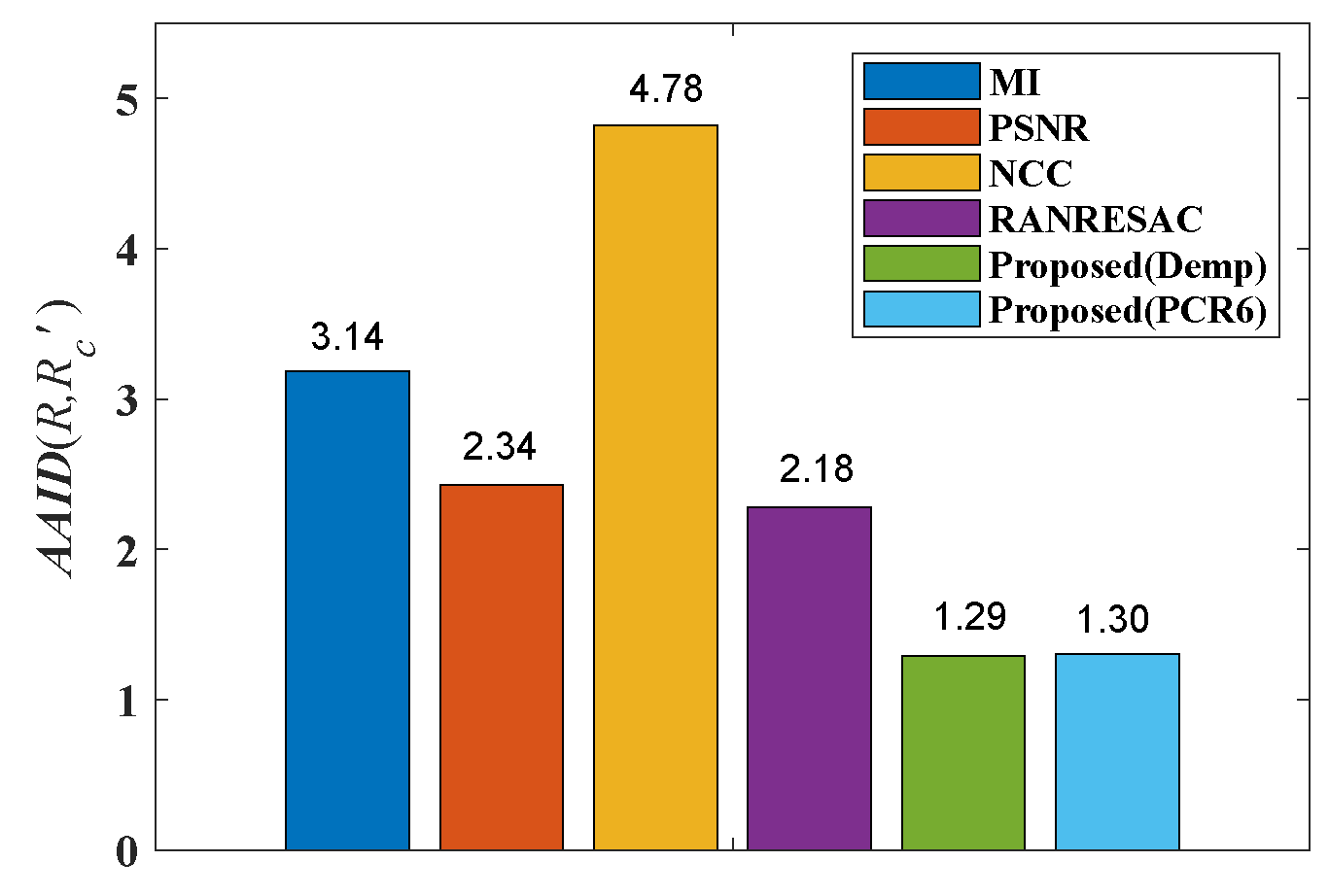
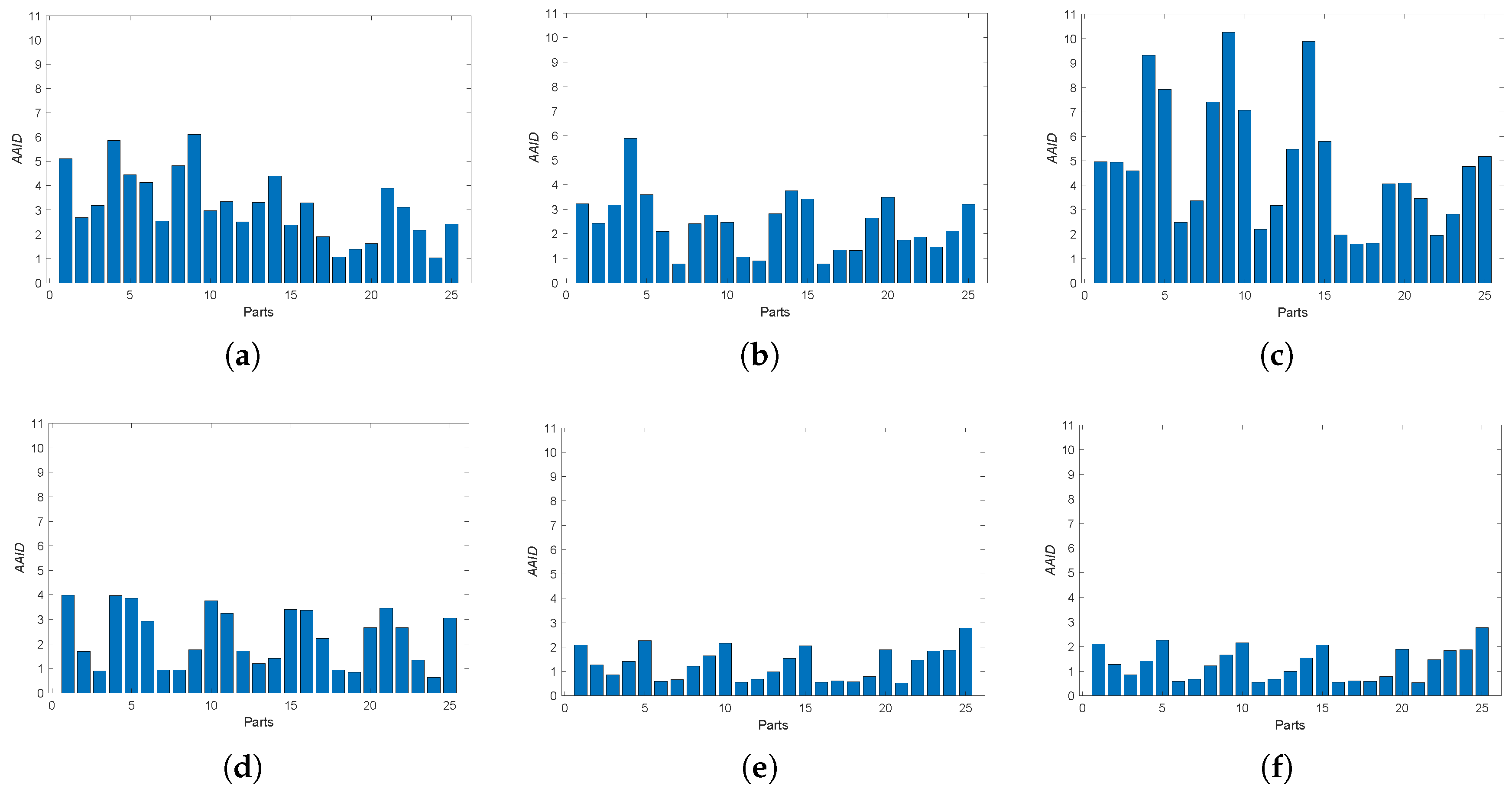
The AAID evaluations for these registration results are compared in Figure 22 and the spatial partition of the AAID evaluation for each result is illustrated in Figure 23, From these two figures, the proposed fusion-based methods achieve better performance and the rightmost parts (parts 5, 10, 15, 20 and 25) have larger AAID than other parts.
According to all the experiments, the proposed fusion-based methods achieve better registration results than those prevailing ones (BRISK, KAZE, SURF, MI, PSNR and NCC). For noisy image registration, the proposed methods also obtain better performance than RANRESAC. This indicates that the theory of belief function can well deal with the uncertainty brought by the selection of keypoint detection algorithms or similarity measures, and the jointly use of the different keypoint detections or similarity measures is effective. Furthermore, from the above provided experiments one sees that the choice of combination rule does not affect the registration performance that much.
6.3. Computational Cost
The computational cost is an important criterion to evaluate an algorithm. We counted the computational costs of the above sparse algorithms and dense algorithms for Cameraman image (Figure 5a) on a Windows 10 Enterprise system equipped with Intel Core i7-7700HQ CPU at 2.80 GHz and 16.00 GB RAM. The platform is MATLAB R2018a. The average execution time comparisons for the sparse algorithms and dense algorithms are provided in Table 2 and Table 3, respectively. Each average execution time is calculated from 100 runs of experiments.
From Table 2 and Table 3, the dense algorithms need more execution time than the sparse algorithms. Furthermore, since the proposed fusion-based method combines the registration transformations generated from the three sparse methods (BRISK, KAZE and SURF) or the three dense methods (PSNR, MI and NCC) and these three methods can be parallely executed, the execution time of the proposed fusion-based method is longer than the most time-consuming one among the three methods.
6.4. Discussion of BBA Generation
The BBA generated in Equation (16) is Bayesian BBA, where all its focal elements are singletons. People in the community of belief function theory may prefer to use the compound focal elements, which usually seems better than only using singletons in Bayesian BBAs. We have also designed experiments of generating non-Bayesian BBAs for image registration using FCOWA-ER (Fuzzy-Cautious Ordered Weighted Averaging with Evidential Reasoning) [35] method. In detail, when multiple image information (image’s intensities, edges and phase angle) are simultaneously considered, image registration can be viewed as a multi-criteria decision making problem. FCOWA-ER (Fuzzy-Cautious Ordered Weighted Averaging with Evidential Reasoning) [35] is a decision making approach under multi-criteria with uncertainty and it generates non-Bayesian BBAs using -cut method (The -cut method used in FCOWA-ER boils down to the Dubois and Prade allocation [36] in this case) when modeling uncertainties. According to the experimental results, non-Bayesian BBAs obtain similar registration results with Bayesian BBAs. Since Bayesian BBAs are easier to generate than non-Bayesian BBAs, we recommend Bayesian BBAs for image registration and do not provide the non-Bayesian BBA based method in this work.
7. Conclusions
In this paper, we proposed a new image registration algorithm based on evidential reasoning. The uncertainty encountered in image registration is taken into account and modeled by belief functions. Image information at different levels are jointly used to achieve a more effective registration. Experimental results show that the proposed algorithm can improve the precision of image registration.
The generation of BBA is crucial in evidential reasoning and most methods are proposed based on applications. In this paper, we generate BBAs from three different image information, i.e., intensity, edge and phase angle. In future work, other image information, such as texture feature and gradient feature, will also be considered and jointly used in image registration. Furthermore, we will attempt to apply the proposed method to color image registration. Different color channels of the color image provide different image information and can be jointly used in image registration. We will also focus on the comparison with the state-of-the-art approaches based on convolutional neural networks (CNN).
Author Contributions
Z.Z., D.H., J.D. and Y.Y. conceived and designed the experiments; Z.Z. performed the experiments; Z.Z., D.H., J.D. and Y.Y. analyzed the data; D.H. and Y.Y. contributed analysis tools; Z.Z., D.H. and J.D. wrote the paper.
Funding
This research was funded by National Natural Science Foundation (Nos. 61573275, 61671370), Postdoctoral Science Foundation of China (No. 2016M592790), Postdoctoral Science Foundation of Shaanxi Province (No. 2016BSHEDZZ46), and Fundamental Research Funds for the Central Universities (No. xjj2016066).
Conflicts of Interest
The authors declare no conflict of interest.
References
- Meher, B.; Agrawal, S.; Panda, R.; Abraham, A. A survey on region based image fusion methods. Inf. Fusion 2019, 48, 119–132. [Google Scholar] [CrossRef]
- Krylov, V.A.; Moser, G.; Serpico, S.B.; Zerubia, J. False discovery rate approach to unsupervised image change detection. IEEE Trans. Image Process. 2016, 25, 4704–4718. [Google Scholar] [CrossRef] [PubMed]
- Torabi, A.; Massé, G.; Bilodeau, G. An iterative integrated framework for thermal-visible image registration, sensor fusion, and people tracking for video surveillance applications. Comput. Vis. Image Underst. 2012, 116, 210–221. [Google Scholar] [CrossRef]
- Zhang, G.; Wu, Q.; Wang, T.; Zhao, R.; Deng, M.; Jiang, B.; Li, X.; Wang, H.; Zhu, Y.; Li, F. Block Adjustment without GCPs for Chinese Spaceborne SAR GF-3 Imagery. Sensors 2018, 18, 4023. [Google Scholar] [CrossRef] [PubMed]
- Saygili, G.; Staring, M.; Hendriks, E.A. Confidence estimation for medical image registration based on stereo confidences. IEEE Trans. Med. Imaging 2016, 35, 539–549. [Google Scholar] [CrossRef] [PubMed]
- Zitová, B.; Flusser, J. Image registration methods: A survey. Image Vis. Comput. 2003, 21, 977–1000. [Google Scholar]
- Guo, X.; Xu, Z.; Lu, Y.; Pang, Y. An Application of Fourier-Mellin Transform in Image Registration. In Proceedings of the International Conference on Computer and Information Technology, Shanghai, China, 21–23 September 2005. [Google Scholar]
- Ask, E.; Enqvist, O.; Svärm, L.; Kahl, F.; Lippolis, G. Tractable and reliable registration of 2D point sets. In Proceedings of the 13th European Conference on Computer Vision, Zurich, Switzerland, 6–12 September 2014; pp. 393–406. [Google Scholar]
- Harris, C.; Stephens, M. A combined corner and edge detector. In Proceedings of the 4th Alvey Vision Conference, Manchester, UK, 31 August–2 September 1988; pp. 147–151. [Google Scholar]
- Rosten, E.; Drummond, T. Machine learning for high-speed corner detection. In Proceedings of the 9th European Conference on Computer Vision, Graz, Austria, 7–13 May 2006; pp. 430–443. [Google Scholar]
- Lowe, D.G. Object recognition from local scale-invariant features. In Proceedings of the International Conference on Computer Vision, Corfu, Greece, 20–25 September 1999; pp. 1150–1157. [Google Scholar]
- Bay, H.; Tuytelaars, T.; Gool, L.V. Surf: Speeded up robust features. Comput. Vis. Image Underst. 2008, 110, 346–359. [Google Scholar] [CrossRef]
- Tola, E.; Lepetit, V.; Fua, P. Daisy: An efficient dense descriptor applied to wide baseline stereo. IEEE Trans. Pattern Anal. Mach. Intell. 2010, 32, 815–830. [Google Scholar] [CrossRef] [PubMed]
- Rublee, E.; Rabaud, V.; Konolige, K.; Bradski, G. ORB: An efficient alternative to SIFT or SURF. In Proceedings of the IEEE International Conference on Computer Vision, Barcelona, Spain, 6–13 November 2011. [Google Scholar]
- Alcantarilla, P.F.; Bartoli, A.; Davison, A.J. KAZE Features. In Proceedings of the European Conference on Computer Vision, Florence, Italy, 7–13 October 2012; pp. 214–227. [Google Scholar]
- Goshtasby, A.A. Image Registration: Principles, Tools and Methods; Springer: Berlin, Germany, 2012. [Google Scholar]
- Santini, S.; Jain, R. Similarity measures. IEEE Trans. Pattern Anal. Mach. Intell. 1999, 21, 871–883. [Google Scholar] [CrossRef]
- Spearman, C. The proof and measurement of association between two things. Int. J. Epidemiol. 2010, 39, 1137–1150. [Google Scholar] [CrossRef] [PubMed] [Green Version]
- Shafer, G. A Mathematical Theory of Evidence; Princeton University Press: Princeton, NJ, USA, 1976. [Google Scholar]
- Han, D.; Dezert, J.; Li, S.; Han, C.; Yang, Y. Image registration based on evidential reasoning. In Proceedings of the 16th International Conference on Information Fusion, Istanbul, Turkey, 9–12 July 2013; pp. 1143–1150. [Google Scholar]
- Fischler, M.A.; Bolles, R.C. Readings in Computer Vision: Issues, Problem, Principles, and Paradigms; Morgan Kaufmann: Burlington, VT, USA, 1987. [Google Scholar]
- Torr, P.H.S.; Murray, D.W. The development and comparison of robust methods for estimating the fundamental matrix. Int. J. Comput. Vis. 1997, 24, 271–300. [Google Scholar] [CrossRef]
- Nakazawa, A. Noise stable image registration using random resample consensus. In Proceedings of the 23rd International Conference on Pattern Recognition, Cancun, Mexico, 4–8 December 2016; pp. 853–858. [Google Scholar]
- Jain, P.; Kar, P. Nonconvex Optimization for Machine Learning. Found. Trends Mach. Learn. 2017, 10, 142–336. [Google Scholar] [CrossRef]
- Pham, D.T. Intelligent Optimisation Techniques; Springer: Berlin, Germany, 2000. [Google Scholar]
- Smarandache, F.; Dezert, J. Advances and Applications of DSmT for Information Fusion: Collected Works IV; American Research Press: Rehoboth, DE, USA, 2015. [Google Scholar]
- Smets, P. The transferable belief model. Artif. Intell. 1994, 66, 191–234. [Google Scholar] [CrossRef]
- Han, D.; Dezert, J.; Duan, Z. Evaluation of probability transformations of belief functions for decision making. IEEE Trans. Syst. Man Cybern. Syst. 2016, 46, 93–108. [Google Scholar] [CrossRef]
- Gonzalez, R.C.; Woods, R.E. Digital Image Processing, 3rd ed.; Pearson Prentice Hall: Upper Saddle River, NJ, USA, 2008. [Google Scholar]
- Canny, J. A computational approach to edge detection. IEEE Trans. Pattern Anal. Mach. Intell. 1986, 8, 679–698. [Google Scholar] [CrossRef] [PubMed]
- Ferreira, D.P.L.; Ribeiro, E.; Barcelos, C.A.Z. A variational approach to non-rigid image registration with bregman divergences and multiple features. Pattern Recognit. 2018, 77, 237–247. [Google Scholar] [CrossRef]
- Xia, X.; Dang, G.; Yao, Y.; Liang, J. Image registration model and algorithm for multi-focus images. Pattern Recognit. Lett. 2017, 86, 26–30. [Google Scholar] [CrossRef]
- Pluim, J.P.W.; Likar, B.; Gerritsen, F.A. Biomedical Image Registration; Springer: Berlin, Germany, 2006. [Google Scholar]
- Leutenegger, S.; Chli, M.; Siegwart, R.Y. BRISK: Binary Robust invariant scalable keypoints. In Proceedings of the IEEE International Conference on Computer Vision, Barcelona, Spain, 6–13 November 2011. [Google Scholar]
- Han, D.; Dezert, J.; Tacnet, J.M.; Han, C. A fuzzy-cautious OWA approach with evidential reasoning. In Proceedings of the International Conference on Information Fusion, Singapore, 9–12 July 2012; pp. 278–285. [Google Scholar]
- Dubois, D.; Prade, H. Representation and Combination of Uncertainty with Belief Functions and Possibility Measures. Comput. Intell. 1988, 1, 244–264. [Google Scholar] [CrossRef]
Figure 1.
Flow chart of sparse approach.

Figure 2.
Different keypoint pairs detected by different keypoint detectors. (a) BRISK. (b) KAZE. (c) SURF.
Figure 2.
Different keypoint pairs detected by different keypoint detectors. (a) BRISK. (b) KAZE. (c) SURF.

Figure 3.
Flow chart of dense approach.

Figure 4.
Flow chart of the proposed image registration.

Figure 5.
Image information at different levels. (a) Gray image. (b) Edge feature image. (c) Reconstructed image using phase angle.
Figure 5.
Image information at different levels. (a) Gray image. (b) Edge feature image. (c) Reconstructed image using phase angle.

Figure 6.
The curve of function .

Figure 7.
Relationship among R, S, and .

Figure 8.
Fence image pair. (a) Reference image. (b) Sensed image.

Figure 9.
Registered results of the proposed methods for Fence image. (a) Dempster’s rule. (b) PCR6.
Figure 9.
Registered results of the proposed methods for Fence image. (a) Dempster’s rule. (b) PCR6.

Figure 10.
Boats image pair and Foosball image pair. (a) Boats reference image. (b) Boats sensed image. (c) Foosball reference image. (d) Foosball sensed image.
Figure 10.
Boats image pair and Foosball image pair. (a) Boats reference image. (b) Boats sensed image. (c) Foosball reference image. (d) Foosball sensed image.

Figure 11.
AAID evaluations of registration results for Boats image pair and Foosball image pair. (a) Boats. (b) Foosball.
Figure 11.
AAID evaluations of registration results for Boats image pair and Foosball image pair. (a) Boats. (b) Foosball.

Figure 12.
Spatial partition of the AAID evaluation for Boats image. (a) Partition method. (b) BRISK. (c) KAZE. (d) SURF. (e) Proposed (Demp). (f) Proposed (PCR6).
Figure 12.
Spatial partition of the AAID evaluation for Boats image. (a) Partition method. (b) BRISK. (c) KAZE. (d) SURF. (e) Proposed (Demp). (f) Proposed (PCR6).

Figure 13.
Spatial partition of the AAID evaluation for Foosball image. (a) BRISK. (b) KAZE. (c) SURF. (d) Proposed (Demp). (e) Proposed (PCR6).
Figure 13.
Spatial partition of the AAID evaluation for Foosball image. (a) BRISK. (b) KAZE. (c) SURF. (d) Proposed (Demp). (e) Proposed (PCR6).

Figure 14.
West Concord image pair. (a) Reference image. (b) Sensed image.

Figure 15.
AAID evaluations of registration results for West Concord image pair.

Figure 16.
Spatial partition of the AAID evaluation for West Concord image. (a) BRISK. (b) KAZE. (c) SURF. (d) RANRESAC. (e) Proposed (Demp). (f) Proposed(PCR6).
Figure 16.
Spatial partition of the AAID evaluation for West Concord image. (a) BRISK. (b) KAZE. (c) SURF. (d) RANRESAC. (e) Proposed (Demp). (f) Proposed(PCR6).

Figure 17.
Concord image pair and Hestain image pair. (a) Concord reference image. (b) Concord sensed image. (c) Hestain reference image. (d) Hestain sensed image.
Figure 17.
Concord image pair and Hestain image pair. (a) Concord reference image. (b) Concord sensed image. (c) Hestain reference image. (d) Hestain sensed image.

Figure 18.
AAID evaluations of registration results for Concord image pair and Hestain image pair. (a) Concord. (b) Hestain.
Figure 18.
AAID evaluations of registration results for Concord image pair and Hestain image pair. (a) Concord. (b) Hestain.

Figure 19.
Spatial partition of the AAID evaluation for Concord image. (a) MI. (b) PSNR. (c) NCC. (d) Proposed (Demp). (e) Proposed(PCR6).
Figure 19.
Spatial partition of the AAID evaluation for Concord image. (a) MI. (b) PSNR. (c) NCC. (d) Proposed (Demp). (e) Proposed(PCR6).

Figure 20.
Spatial partition of the AAID evaluation for Hestain image. (a) MI. (b) PSNR. (c) NCC. (d) Proposed (Demp). (e) Proposed (PCR6).
Figure 20.
Spatial partition of the AAID evaluation for Hestain image. (a) MI. (b) PSNR. (c) NCC. (d) Proposed (Demp). (e) Proposed (PCR6).

Figure 21.
Lifting Body image pair. (a) Reference image. (b) Sensed image.

Figure 22.
AAID evaluations of registration results for Lifting Body image pair.

Figure 23.
Spatial partition of the AAID evaluation for Lifting Body image. (a) MI. (b) PSNR. (c) NCC. (d) RANRESAC. (e) Proposed (Demp). (f) Proposed (PCR6).
Figure 23.
Spatial partition of the AAID evaluation for Lifting Body image. (a) MI. (b) PSNR. (c) NCC. (d) RANRESAC. (e) Proposed (Demp). (f) Proposed (PCR6).


Table 1.
Projective transformation and its two specializations.
| Similarity | Affine | Projective |
|---|---|---|
 |  |  |
Table 2.
Average execution time comparison for sparse algorithms (unit second).
| Method | Noise-Free Images | Noisy Images |
|---|---|---|
| BRISK | 0.2847 | 0.2832 |
| KAZE | 0.1348 | 0.1304 |
| SURF | 0.0431 | 0.0437 |
| RANRESAC | – | 6.2648 |
| Proposed (Demp) | 0.3934 | 0.3933 |
| Proposed (PCR6) | 0.3938 | 0.3989 |
Table 3.
Average execution time comparison for dense algorithms (unit second).
| Method | Noise-Free Images | Noisy Images |
|---|---|---|
| MI | 16.7622 | 16.4789 |
| PSNR | 12.8583 | 13.4214 |
| NCC | 14.7187 | 15.1050 |
| Proposed (Demp) | 17.0734 | 16.7945. |
| Proposed (PCR6) | 17.0812 | 16.8729 |
© 2019 by the authors. Licensee MDPI, Basel, Switzerland. This article is an open access article distributed under the terms and conditions of the Creative Commons Attribution (CC BY) license (http://creativecommons.org/licenses/by/4.0/).
Share and Cite
MDPI and ACS Style
Zhang, Z.; Han, D.; Dezert, J.; Yang, Y. A New Image Registration Algorithm Based on Evidential Reasoning. Sensors 2019, 19, 1091. https://doi.org/10.3390/s19051091
AMA Style
Zhang Z, Han D, Dezert J, Yang Y. A New Image Registration Algorithm Based on Evidential Reasoning. Sensors. 2019; 19(5):1091. https://doi.org/10.3390/s19051091
Chicago/Turabian StyleZhang, Zhe, Deqiang Han, Jean Dezert, and Yi Yang. 2019. "A New Image Registration Algorithm Based on Evidential Reasoning" Sensors 19, no. 5: 1091. https://doi.org/10.3390/s19051091
Note that from the first issue of 2016, this journal uses article numbers instead of page numbers. See further details here.