1. Introduction
About 30 million amputees are residing in low income countries [
1,
2]. Among those, only 5% to 15% are capable to receive a much-needed prosthesis [
3]. Although the popular state-of-the art prostheses used in developed countries offer several advanced features, its application is hindered in low income developing countries primarily due to high cost, different functional demands, cultural issues, and unavailability of components locally [
4,
5].
Gait parameters of trans-femoral amputees including step length, inter-leg symmetry, hip exertion, and involvement of upper body are highly affected [
6]. Over the years, there have been considerable efforts to develop affordable prostheses for trans-femoral amputees in developing countries [
6,
7,
8,
9]. These efforts have resulted in a variety of lower limb prosthetic designs at reduced cost. However, these prosthetic designs include low-end technologies like manual locking knee joints, the weight activated braking mechanism, and polycentric knee joint mechanisms [
2,
6,
10,
11,
12]. In manual-locking-knee joints, knee stability is improved by providing more stiffness which renders lower speed and increased energy expenditure during gait [
10]. Problems associated with stiff-legged gait were overcome by incorporating weight activated brakes with a knee joint. A typical weight activated arrangement suffers from limitations of abnormal gait and delayed initiation of swing phase [
10]. Polycentric knee joint mechanisms were quite useful in developed countries and now, with some modifications, are being developed to suit the needs of low-income countries. The polycentric knee joint linkages can be configured to improve the stability in the stance phase with fair swing phase initiation. It does impose a limitation. As the extent of stability is increased in the stance phase, the swing phase initiation gets delayed proportionally [
8,
13]. In this regard, some recent prostheses such as Le Torneau polycentric knee (Limbs International, El Paso, TX, USA), Stanford-Jaipur leg (Stanford University, Stanford, CA, USA), Remotion Knee (D-Rev), SASPL knee joint LCKnee (Andrysek et al.) and a three axes knee (Arelekatti et al.) at MIT [
2,
10,
11,
12] have been developed.
Le Torneau knee and Stanford-Jaipur knee joints have a similar polycentric design of four-bar linkage with little to offer other than stance phase stability. On the other hand, Remotion Knee is the advanced version of Stanford-Jaipur knee with curvature mimicking to address late stance phase initiation [
2,
10]. Studies have revealed that such prosthetic designs though provide a low-cost solution to a grieving population, it does not take into account the need for an early stance flexion-extension and properly timed late stance flexion [
11,
12]. The basic biomechanical aspects, when overlooked, can result in many psychological, physiological, and socio-economic problems [
14]. Abnormal and sub-normative gait puts immediate and extended costs in terms of psychological stigma and socio-economic distress, whereas in the longer term it results in musculoskeletal impairments and adversely affects the physiological equilibrium [
15,
16,
17,
18]. It suggests that the excessive focus on cost reduction alone cannot serve the desired purpose and low-cost prostheses must also have the ability to provide a gait kinematics closer to that of a healthy person.
Also, Andrysek et al. and Arelekatti et al. addressed the problem of abnormal gait in low-cost passive prostheses. Andrysek et al. SASPL engages or disengages depending on the loading of the prosthetic limb during weight bearing but is not able to provide early stance flexion-extension and optimal swing phase damping [
11]. Arelekatti et al. incorporated able-bodied gait kinematics using an automatic early stance lock for stability, a linear spring for early stance flexion-extension and swing control. The design suffers from few limitations such as the necessity of full knee extension at the end of swing phase and failure to lock the knee before stance phase that can lead to instability and risk of fall. Further, due to the lack of any clinical gait analysis, the study does not establish the extent of improvement in amputee kinematics towards normative gait [
12]. It offers sufficient motivation to look for a new prosthesis design and control scheme that can enable able-bodied gait kinematics in trans-femoral amputees at an affordable cost in developing countries. So far, all developed prostheses designed for developing countries are primarily passive in nature, the authors believe that a variable damping can provide the subject with comfortable walking, thereby yielding the desired results at a low cost.
In this paper, a novel low cost lower limb prosthesis was developed and its clinical testing and analysis are presented. A new foot plantar insole feedback-based control strategy was developed and implemented to provide necessary damping using an MR damper. The prosthesis enables the amputee to realize the able-bodied normal gait kinematics and meets the functional, socio-economic, and aesthetic needs of a trans-femoral amputee and is affordable even in low-income economies. The paper also focuses on essential design features and requirements of a prosthesis to assess its commercial viability in these countries such as low cost, light-weight, functionality, biomechanically appropriate, durable, using locally available materials etc., based on the recommendations of ISPO Consensus Conference on Appropriate Prosthetic Technology in Developing Countries and elsewhere [
19,
20,
21,
22]. The details are discussed later in
Section 5.7. The key objective of this work is to enable lucid design for development of an affordable prosthesis in low-income economies.
2. Prosthesis Design
This rationale of the prosthesis design is presented in this section. The trans-femoral prosthesis shall serve the major function of providing stability during stance phase and controlled flex-extension during the swing phase of a gait cycle. In the stance phase, the stability was ensured by providing suitable resistance to knee joint flexion while the user transfers body weight from the sound/healthy limb to the prosthetic limb. Similarly, the swing phase flex-extension was controlled by regulating walking speed [
22]. Both the functions were achieved by including springs and dampers in the design [
3]. Either a variable damping system or a system with multiple dampers is required for a variable damping system incorporated in state of art active prostheses, whereas multiple dampers are used in recent advanced passive prostheses. The multiple-damper approach inherently puts the design at disadvantage in terms of serviceability [
10,
11].
A study conducted by Herr and Wilkenfeld [
23] serves as the theoretical background for our design to realize able-bodied gait kinematics. The authors used an MR knee prosthesis to adapt knee damping using local sensing of knee force, torque, and position. A few recent studies conducted by Xu et al. [
24], Park et al. [
25], and Fu et al. [
26] have also attempted to design a lower limb prosthesis based on an MR damper. Complex sensing, data-driven AI control and lack of local climatic adaptations as well as increased cost of the prosthesis arising from various factors ranging from non-inclusion of off-the-shelf components or locally manufactured components increased the inherent cost, making it unsuitable for applications in low-income economies. Further, the control architecture based on stiff tracking of the knee angle should be avoided in order to enable the amputee to use the prosthesis more interactively, rather than reacting to it [
24]. Therefore, the potential of prostheses based on MR damper remain untapped in such low-income economies due to the unavailability, complexity, and incurring cost of design and manufacturing [
20,
23,
27].
It is proposed that a single damper with a controllable damping capacity, such as an MR damper, if used with suitably designed sensing modality, driving circuitry, and control architecture, can provide able-bodied gait kinematics yet at a cost below par with advanced passive prostheses. Here, strategically placed sensors on the plantar insole provide sufficient information for normal gait kinematics, thereby enabling the control of the current in the MR damper during the different phases of a gait cycle. This forms the basis for the design of a simple MR damper-based knee joint mechanism and its control with plantar insole feedback.
2.1. Mechanical Design
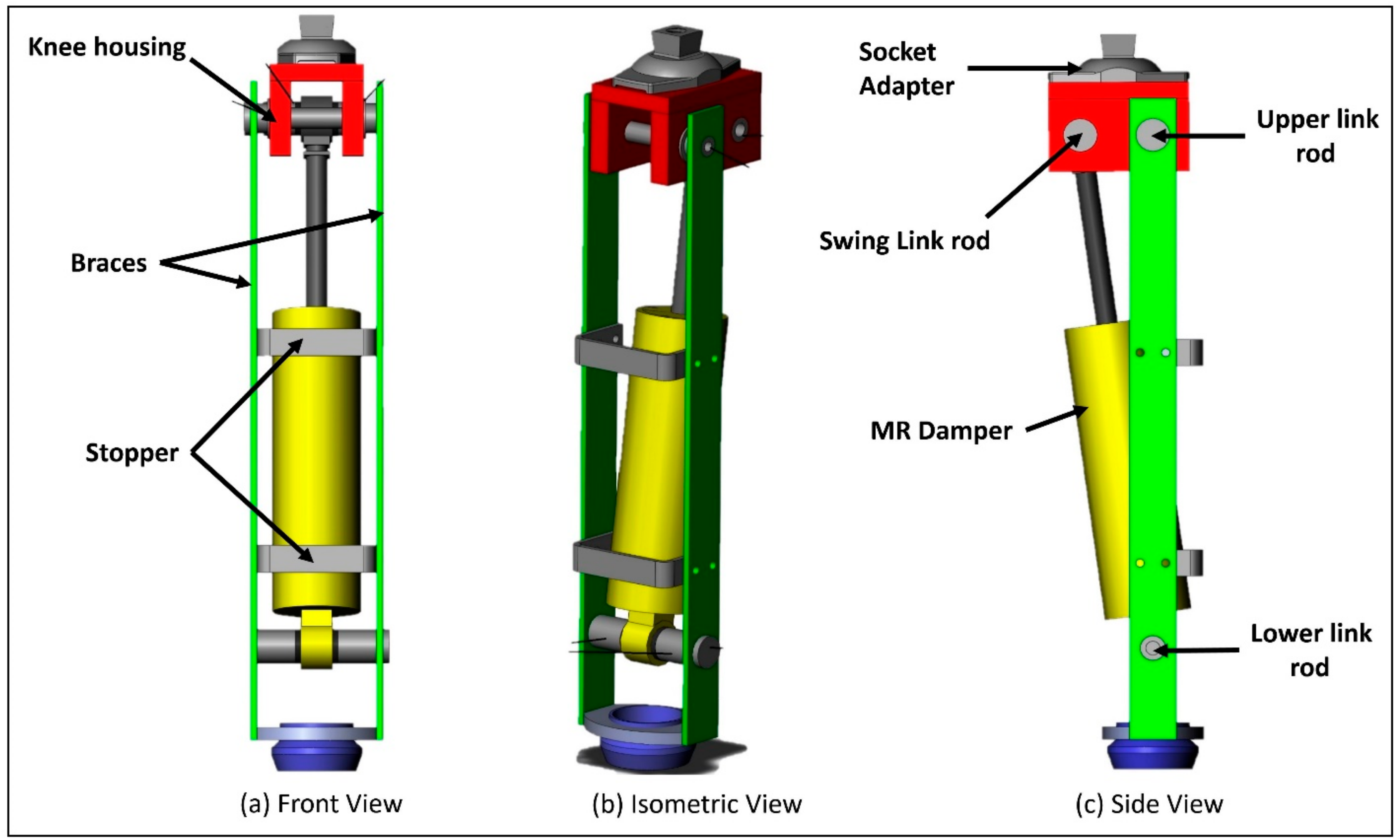
The design of the prosthesis’ mechanical structure is shown in
Figure 1. The design includes an MR damper, a hinge-type knee joint, and braces to support the leg assembly. In the MR damper, modulation of magnetic field strength can offer variable resistance to the flow of MR fluid. Placement of electromagnets around the piston rod and MR fluid as a working medium inside a hydraulic cylinder can result in a variable damping [
20,
23,
27]. Damping can be modulated by changing the current flowing in the coils of the electromagnet. A variety of MR dampers are available to suit lower limb prostheses. In this study, a commercially available MR damper (Make: Lord Corporation, Cary, NC, USA; Model RD-8041 with a stroke length of 74 mm, and extended length of 248 mm) was employed in the prototype.
The piston rod and outer cylinder of the MR damper were fixed to the knee joint and the shank individually with swing link and lower-link rods. The upper-link and lower-link rods are attached to the braces. The upper link rod and swing-link rod form the knee axis and the control axis of the prosthesis, respectively; the upper link rod along with knee body articulates the knee braces via the knee axis. The control axis primarily responds to the ground reaction forces that cause relative motion between the knee and the braces. The swing-link rod transfers the forces generated by the MR damper during locomotion. The biomechanical mechanism of the control axis has been extensively reported elsewhere [
26]. The control of the prosthesis in both the stance and swing phases was achieved by the same mechanical assembly and no separate mechanical component was used to lock the knee. The upper part of the knee joint (knee body) was connected to a socket connector to fasten the socket properly. The braces along with MR damper form the shank of the leg. It was connected to a Sach foot with a shank connector. The socket and shank connectors are connected to the knee and ankle adapters used by prosthetists for proper alignment of the prosthesis to the individual amputee. Knee Movement has been restricted to 90 degrees with protective bars (stoppers) placed in the forward direction of the damper. Custom designed components were used for link rods, plates, braces, and knee joint to meet the design specifications. Proper motion of the knee joint was ensured by simulating the solid model design in Solid Works
®. During the simulation along the entire knee range, there was no interference between the joint links, bars, plates, and braces. With proper machining of all the custom components, the mechanism was assembled by bolting the braces to the knee joint. The MR damper was shoulder-bolted with the links of the assembly. Bearings were employed for smooth motion of joint between knee body plates and link rods. Off-the-shelf components such as connectors, adaptors, and the Sach foot were employed to extend the design with existing prosthetic components.
2.2. Sensing Mechanism
Plantar insoles are extensively used for gait analysis of many locomotion impairments [
28,
29]. Although plantar insoles provide information during only the stance phase, it is sufficient for most of the rehabilitation support systems, posture and balance control [
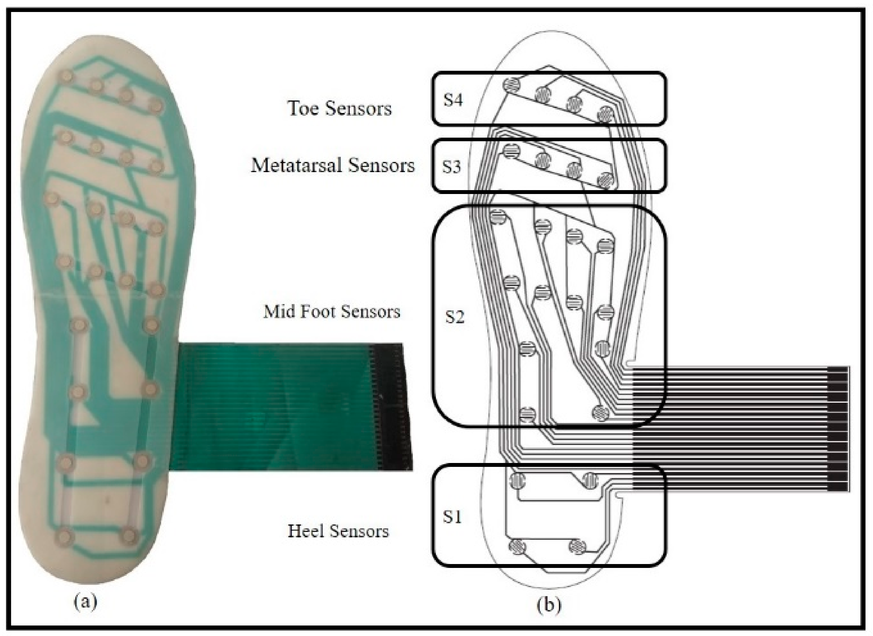
28]. Most of the plantar insoles employ a discrete number of sensors to obtain the required information; the minimum number of sensors vary from 2 to 16, or more depending upon the need [
28]. Taking into account the advantages of foot plantar insoles, a novel sensing method was developed to control the prosthesis both in the stance and swing phases. It is composed of 24 switches strategically placed on the heel (S1), mid-foot (S2), metatarsal (S3), and toe (S4) of the plantar insole as shown in
Figure 2. The sensor placement was determined by considering dominant pressure points of the plantar surface during walking as reported by Razak et al. [
28]. The rationale for considering sensors on plantar insole lies in the wheel-like-behavior of plantar foot and its subsequently resulting roll-over shapes (ROS) [
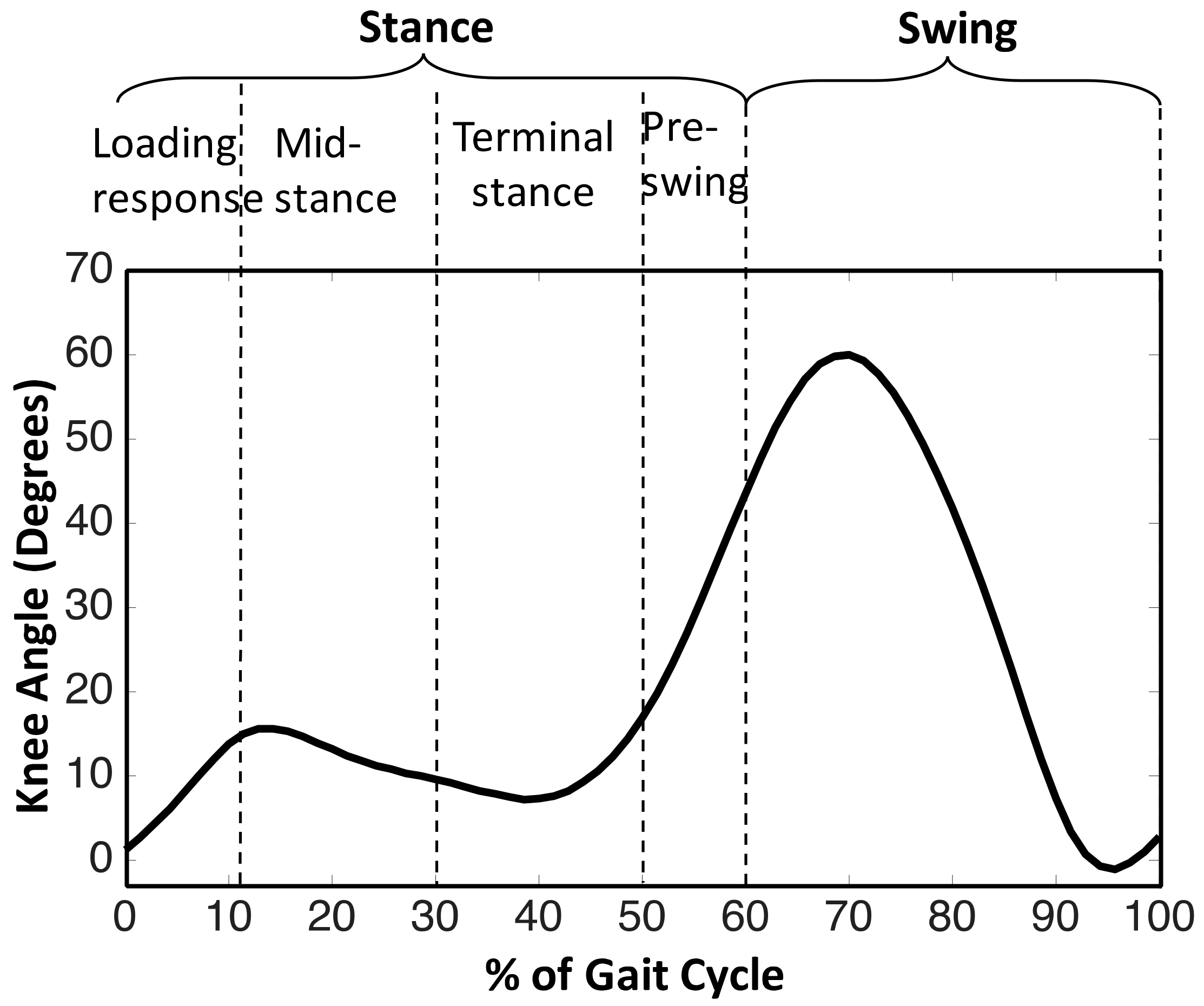
30,
31]. Such ROSs are formed for various biomechanical events corresponding to different phases of a gait cycle of human locomotion i.e., loading response, mid-stance, terminal stance, pre-swing, and swing [
32]. The progression of a typical gait cycle of a healthy individual along with subsequent phases and events are depicted in
Figure 3. As the five segments are sequential in nature, the phases are distinctly noticed due to the formation of ROSs based on the combination of states of four groups or sensors placed on the foot plantar insole. The grouping of the 24 sensors into 4 groups is shown in
Figure 2b. The stance phase events can be related to different combinations of the states of four sensor groups as tabulated in
Table 1. If the state of any of the sensors in a group is high, then the state of the same group is assigned the value of 1.
The circuitry and mechanical dimensions of the insole were designed using Coral Draw®. The insole was printed using the silk screen printing process (Keywell Industrial Co., Noida, UP, India). In this process, silver-conducting ink and dielectric was used to print the circuit. While designing the insole, it was important to determine the minimum thickness of the dielectric layer and the amount of pressure that the insole may undergo during walking. It enables the designer to use an optimum thickness of the dielectric layer that is sufficient to trigger the events. For the initial prototype, this trade-off between minimum dielectric layer thickness and maximum loading was made using the ground reaction force (GRF) profile of the amputee on a force plate.
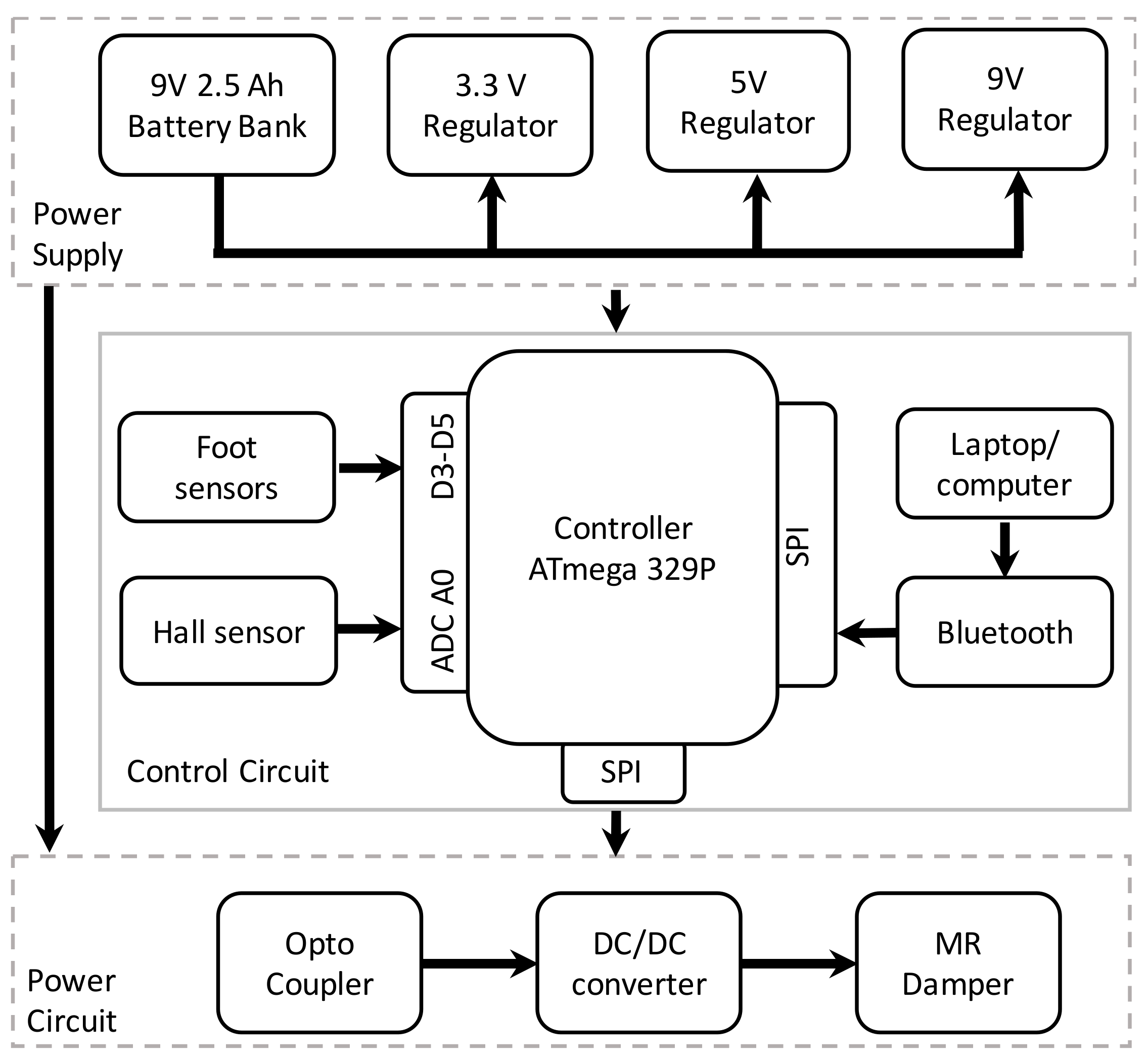
2.3. Embedded System
To feed the desired current to the MR damper at the given time instant, an electronic circuit that uses sensor readings was designed to regulate the current. The MR damper requires variable current to provide variable damping; the MR damper current can be varied by varying the input DC voltage across the load. It was achieved by a step-down DC/DC converter, controlled by a pulse width modulation (PWM) scheme. The duty cycle of the PWM signal was varied to reduce the error in the reference and actual feedback current. Error in reference and feedback current can be reduced to a permissible extent in desirable time by employing a proportional integral (PI) controller. The actual feedback current was measured with a Hall current sensor ACS712. The power circuit includes a battery bank rated at 9 V and 2.4 Ah, a power MOSFET, freewheeling diode, low pass LC filter, and MR damper.
The power and control circuits were isolated with an optocoupler and gate-driving circuit to ensure smooth operation. The control circuit includes the sensing mechanism along with a control unit as shown in
Figure 4. A microcontroller is the central component of the control unit, that in-turn is the brain of the total signal processing system. The primary objective of the microcontroller is to control the power driving unit when required to change the damping. After careful analysis of the requirements, the Atmel mega (ATmega) 329P microcontroller was chosen for this work for its low cost, versatile characteristics, and more advanced features. The necessary processing of sensor signals and implementation of control algorithm was achieved with the firmware. The details of the components of the embedded system are given in
Table 2.
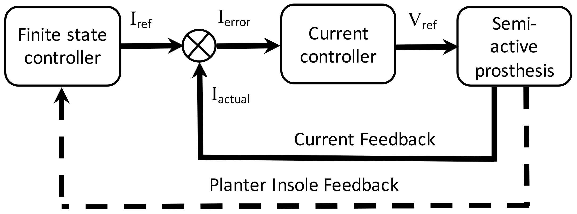
2.4. Control Architecture
A two-level control scheme was employed to achieve able-bodied gait kinematics as depicted in
Figure 5. The control approach involves a finite state controller as a secondary controller and a conventional PI controller as a primary controller. The secondary controller generates the required current references for the MR damper using a finite state machine that ultimately modulates the impedance of the gait, depending on the gait event segment. The primary controller is a closed loop PI controller for MR damper current, which compensates for the load transfer dynamics, thus enabling the faithful tracking of current references with a higher bandwidth and accuracy as compared to its open loop counterparts. Prosthetic control is different from robotic control where the oscillatory response was avoided and the system was tasked to follow a stiff trajectory. PD, P, PID, sliding mode, and hysteresis controllers are inherently suitable for stiff tracking, whereas a PI controller offers a more suitable response. Furthermore, a PI controller is the most widely used current controller in industrial applications, and its incorporation would attract more commercial acceptability.
This ordered behavior of state machines are utilized in neuro-prostheses with event triggered control [
34,
35]. The states of the finite state machine were determined by considering various demanded requirements [
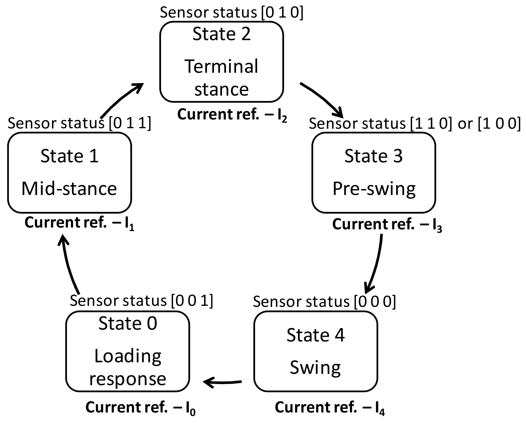
36]; here we intend to achieve the flexion-extension of the knee during the stance phase with a high degree of stability and a suitably damped swing phase to adjust the walking speed. In order to meet the stated requirements, a gait cycle with five segments/phases as described earlier were considered i.e., loading response, mid-stance, terminal stance, pre-swing, and swing. The above states are illustrated in
Figure 6. Though there could be any number of states that can be used to form a state machine, as previous studies have reported, the introduction of a foot plantar insole with four sensor groups provides a total of 16 states, out of which 15 belong to stance phase and one to swing phase. Due to the ROS trajectory during level walking, only 7 states of stance can be assigned to four phases as tabulated in
Table 1, whereas the remaining 8 states of stance do not represent any of the ROS segments. The available literature suggests that consideration of 4 states have successfully resulted in desired kinematics in the stance phase [
27], whereas treatment of swing phase as a single state does not deviate much from the same [
37].
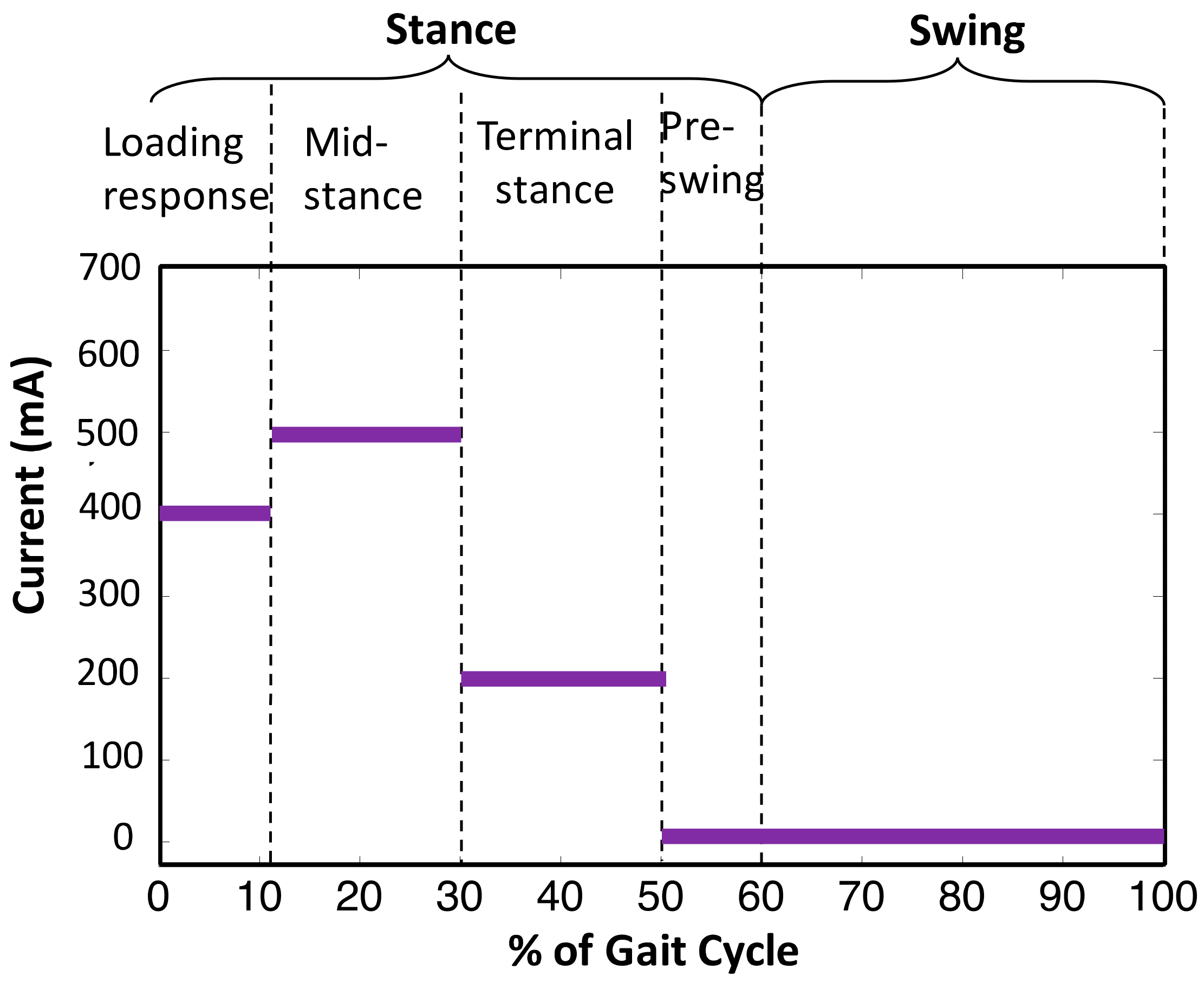
In state 0, the knee flexes near to the maximum stance flexion. A relatively high damping was applied during this state to prevent buckling at the knee due to the user’s weight. During state 1, the knee begins to extend after maximum flexion. The rate of extension was lower than that of flexion during state 0, thereby requiring a high damping. The level of damping shall account for slow extension in order to avoid potential slamming of rotating parts to the knee housing and stoppers. State 2 involves the flexion-extension while the heel is off the ground and the sound limb is sharing the body weight, a moderate damping shall serve the purpose here. State 3 encounters the extension with a high rate of change and low body weight bearing; a low damping will provide the desired profile. The final state (state 4) represents a large knee flexion and associated extension after flexing to its maximum. The rate of change of flexion-extension suggests a very small damping for the same. All states can be tuned to suitable current references which can be accurately followed by a well-designed PI controller. The response of the PI controller must be fast and accurate as it lies in the inner loop of the control architecture.
3. Methods
The developed prosthesis was tested on a 24-year-old male (1.63 m, 60 kg) unilateral trans-femoral amputee in India as part of the target population. The subject was using a commercially available passive prosthesis (single axis extension assisting prosthetic knee joint) for the last three years post traumatic amputation. The amputee mobility predictor (AMP) score of the amputee was more than 35, i.e., above the K3 activity level.
Table 3 shows the measurement of amputee and component used in the proposed prosthesis. A custom made Ischial containment socket was designed for the amputee by a licensed professional prosthetist. The prosthesis was assembled according to the measurements of the amputee.
The dynamic alignment of the prosthesis was performed by the trained prosthetist who is one of the co-authors of the current work. The participant did not have any musculoskeletal injuries, sensory or neurological impairment or related disabilities other than trans-femoral amputation. The study was approved by the All India Institute of Medical Sciences ethics committee (Ref. No. IEC-35/09.02.17). The participant was explained the experiment protocols before starting the experiment and written consent was obtained.
3.1. Parameter Tuning and Training
The controller parameters were tuned sequentially considering one controller at a time. Firstly, the innermost current controller was designed for the electrical time constant of the MR damper, so that a maximum current of 1A could be attained with a desired speed and accuracy. The gain parameters were tuned separately, and the speed was optimized after attaining a fair accuracy. It was achieved by the Ziegler–Nicholas method of tuning the PI controller. After tuning of the PI controller, i.e., the current controller, the prosthesis was fitted on the subject for familiarization. When the subject was able to walk properly with certain level of comfort, the prosthesis was then considered ready to be tuned for the secondary level of control. As stated in
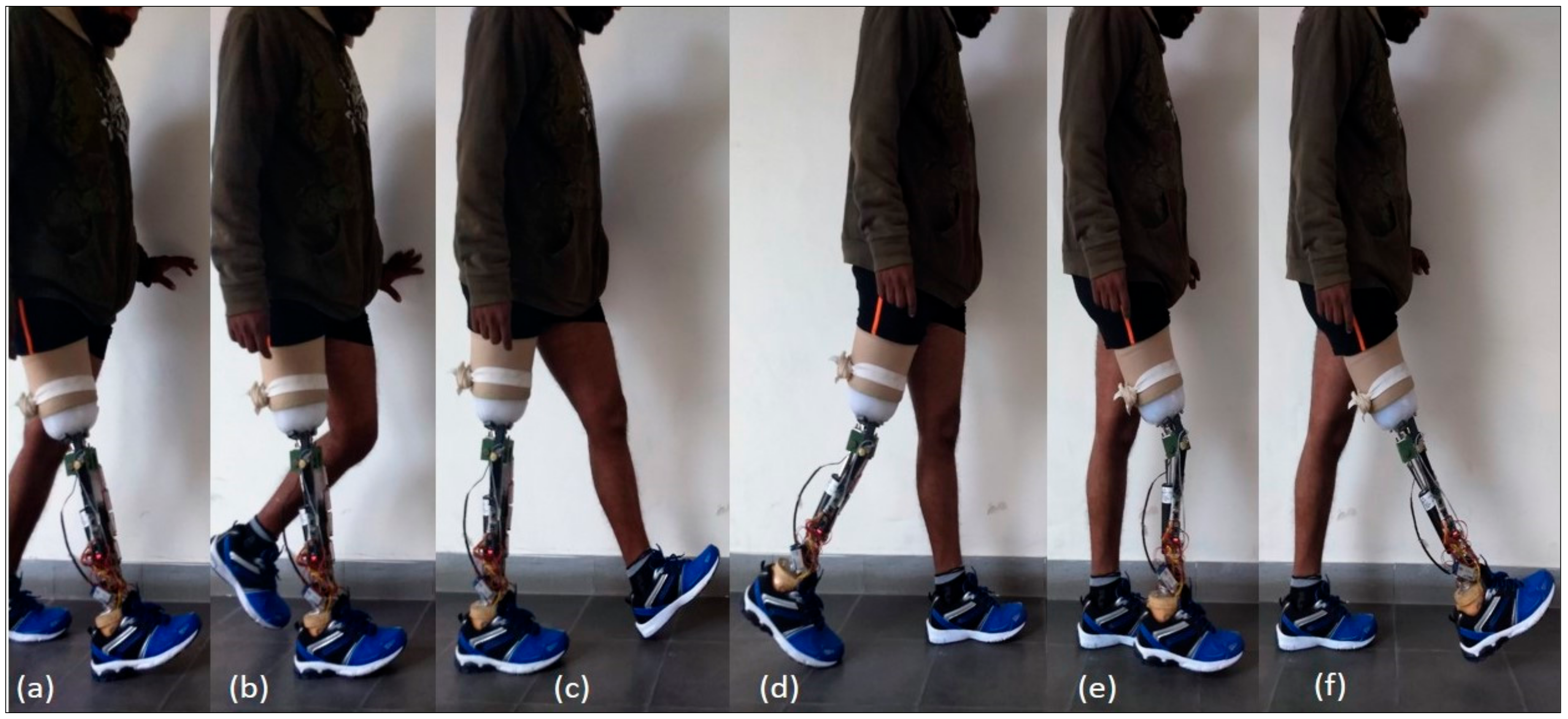
Section 2.2, a gait cycle was segmented into 5 states (shown in
Figure 7), and for each state one current reference was to be set, thereby a total of 5 parameters of the finite state controller needed to be tuned.
Figure 7e,f depict the same damping as shown in
Figure 8, however, for the sake of visualization, they are shown separately. It was usually straight-forward to make an initial guess of only 5 parameters. However, to avoid unnecessary discomfort to the subject, the parameters were tuned sequentially in each state depending upon the feedback from the subject and the prosthetist.
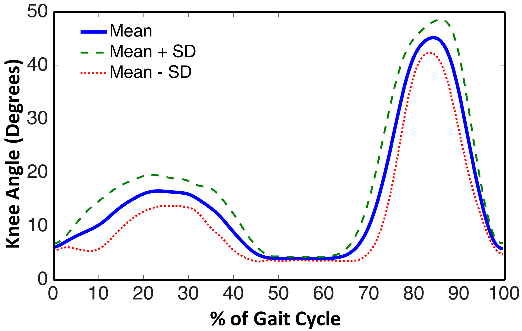
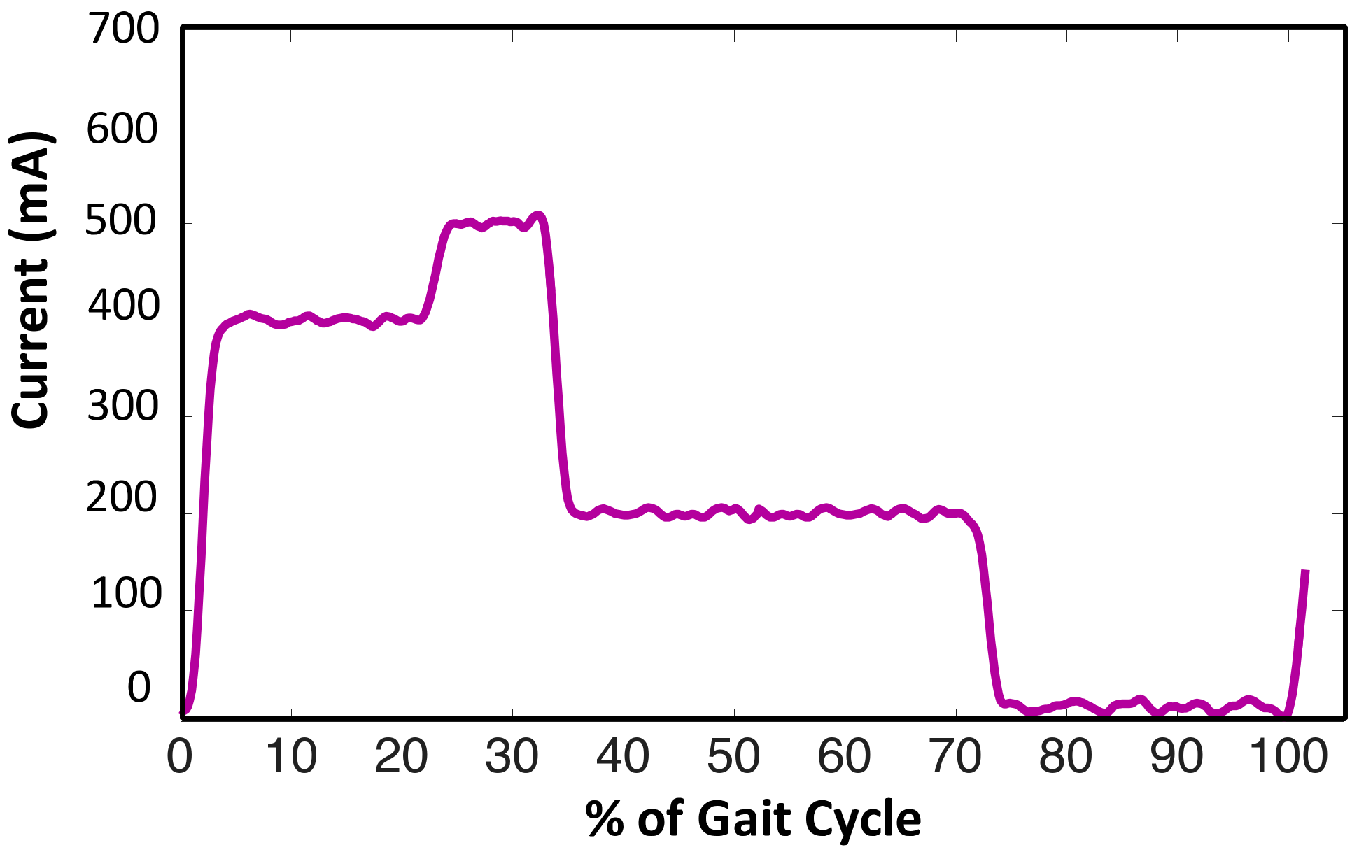
After obtaining an initial set of parameters, all the values were iteratively fine-tuned to attain a gait characteristic closer to that of a healthy individual. The knee angle was used as an essential quantitative measure to observe the performance. Subject feedback along with that of the trained prosthetist was considered primary qualitative criteria to tune the parameters. This type of tuning avoids unnecessary discomfort to the subject. The final set of current references are depicted in
Figure 8.
Once the prosthesis was tuned for level walking, the subject was given sufficient training time to get proper acclimatization to it. A number of training sessions were conducted for the subject in accordance with the training methods reported in several studies [
38,
39,
40,
41]. The training was usually specific to each subject, thus the sessions were planned by a trained prosthetist keeping in view that the subject had been using a passive prosthesis for a long duration. When the subject actively started to walk on level ground, the experimental data was collected for analysis.
3.2. Experimental Setup
The subject was asked to walk on a 24.38 m (80 feet)-long corridor at a uniform subject comfortable speed. The initial walk of 3.05 m (10 feet) and 3.05 m of walk towards the end were excluded to avoid any deviation in biomechanical data that may arise due to acceleration and deceleration during beginning and ending, respectively. Hence the walking variables were measured over an active length of corridor of 18.29 m (60 feet) which was assumed to be uniform.
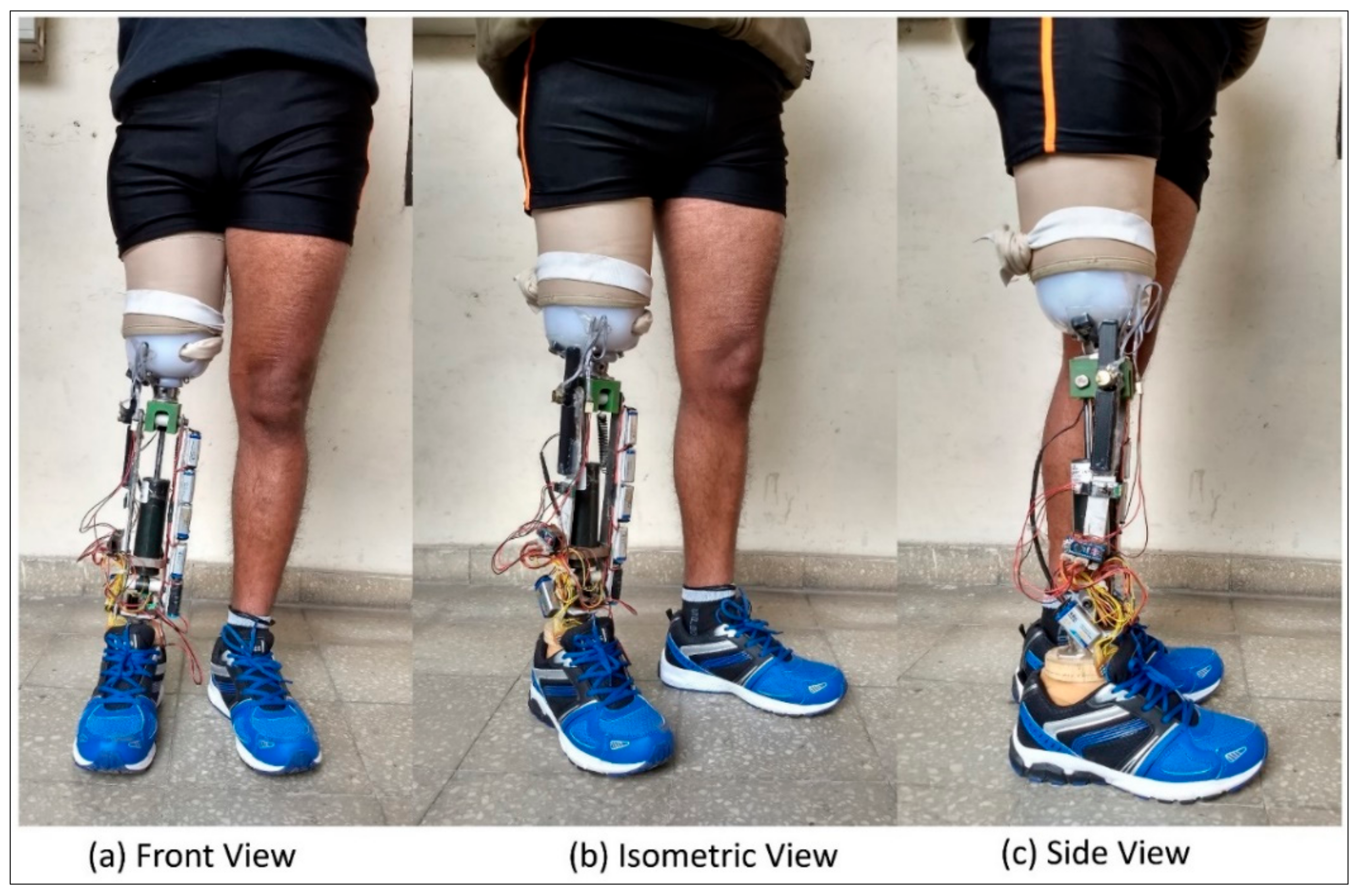
For the subject (fitted with the prosthesis as shown in
Figure 9), a total of 10 trials were conducted; one trial included initial standing of 10 s and then level walking of 24.38 m (80 feet) followed by standing for 10 s. The starting, stopping, and other necessary instructions were provided verbally to the subject. After each trial, the subject was asked to take a minimum of 2 min rest which could be increased based on subject’s requirement. In order to evaluate the performance of the developed prosthesis, the data obtained from the knee goniometer, foot plantar insole, on-board clock, and the voltage and current sensors were transmitted wirelessly with a Bluetooth module to a remote desktop.
A freeware serial port terminal application (CoolTerm, version 1.4.7) was used to record the data with a sampling frequency of 100 Hz. The data was filtered in MATLAB® R2015b using a low pass Butterworth filter of 4th order with a cut-off frequency of 10 Hz. The cut-off frequency of 10 Hz was preferred to filter the data as the frequency of human motion was typically less than 5 Hz. The signal was further smoothened using a 5-point moving average filter.

 and
and 


