2.1. RISING-2 Microsatellite
The RISING-2 microsatellite is a 50-kg platform developed jointly by the Tohoku and Hokkaido universities in Japan [
8]. It constitutes a substantial improvement over the SPRITE-SAT, which was launched in 2009 and subsequently called the RISING satellite after its launch [
9]. Tohoku University developed a satellite bus system for the RISING-2 platform, including a main onboard computer called the Satellite Central Unit (SCU). Hokkaido University developed the mission payload instrumentation for Earth observation, including a controller unit called the Science Handling Unit (SHU; manufactured by AD Co., Ltd., Sagamihara, Japan).
The RISING-2 microsatellite was designed with the form of a 50-cm cube and a weight of about 43 kg, such that it could be adopted as a secondary small payload on an H-IIA launch vehicle. The satellite was launched successfully by the H-IIA from Tanegashima Space Center in Japan on 24 May 2014, along with the primary payload (the Advanced Land Observing Satellite-2 satellite) and three other secondary small payloads (nano/microsatellites, each <50 kg). The RISING-2 microsatellite was placed into a Sun-synchronous orbit at the altitude of 628 km with the local Sun time on the descending node of 12:00. Three years after its launch, the satellite remains active, although its operation has become less frequent.
The three-axis active attitude control system of the RISING-2 microsatellite provides off-nadir pointing capability in order for the optical mission payload instruments to maintain focus on a specific location on the ground [
10]. This capability not only enhances the revisit frequency for the selected site, it also increases the number of spectral bands available for the site by wavelength scanning with the LCTF of the HPT. The location of the site to be observed by the HPT is stored preliminarily in the memory of the SCU, and the HPT observation is executed at a scheduled time by sending the stored commands from the SCU to the SHU.
The SHU controls both the power supply and the data acquisition by the mission payload instruments. Acquired images are stored temporarily in the 8 MB Static Random Access Memory (SRAM) of the SHU. As the data volume of an image taken by the HPT is about 650 kB, the HPT can capture up to 12 images sequentially. As described later, the HPT has the potential for a hyperspectral sensor that is capable of obtaining images in hundreds of spectral bands, but it is not realized because of the limitation of the number of images stored temporarily. The SRAM allows fast access, but it is a volatile memory unit, and it loses stored data when the power is off. After an observation sequence, the images are combined with ancillary data, and transferred to the 128-MB non-volatile flash memory of the SHU without image data compression. When the RISING-2 microsatellite is visible from the ground station located at Tohoku University, the data in the flash memory are downlinked via S-band telemetry at a data rate of 50 kbps [
8], which means that it takes at least 1.7 min to downlink one image. Therefore, because of this limitation of the data rate, fewer than 10 images can be downlinked in one day.
2.2. High Precision Telescope (HPT)
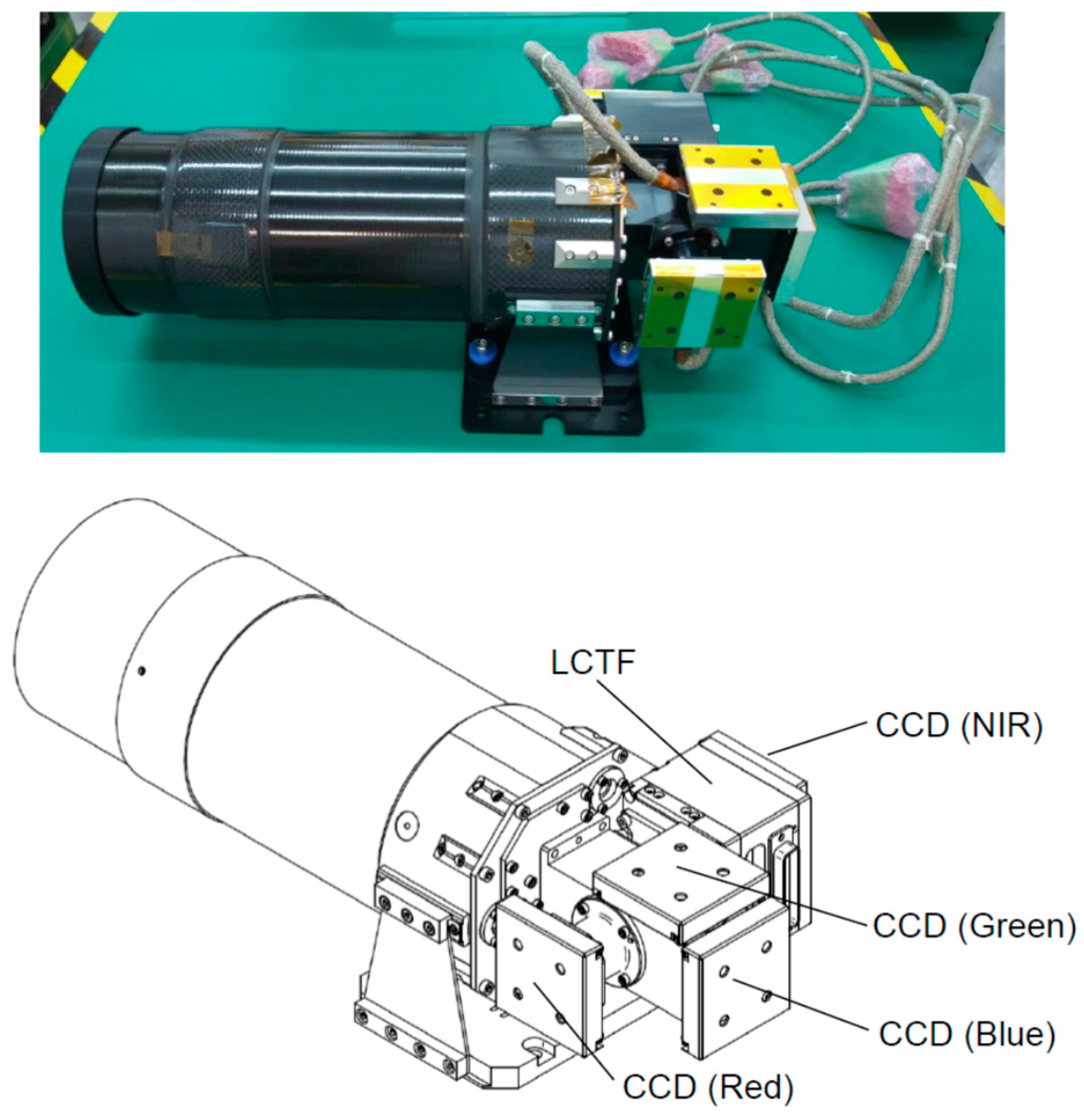
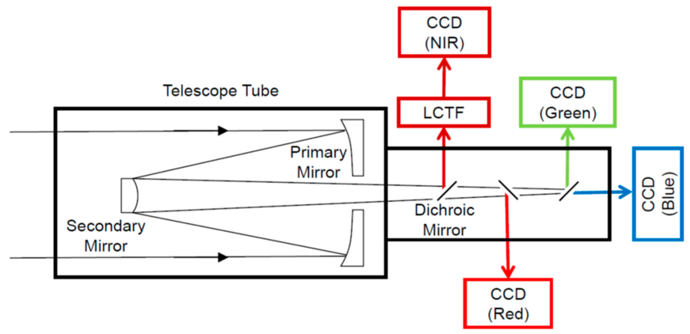
The HPT installed on the RISING-2 microsatellite is a high spatial resolution multispectral sensor equipped with four charge-coupled device (CCD) image sensors for red, green, blue, and near-infrared (NIR) bands split by dichroic mirrors, as shown in
Figure 2 and
Figure 3. The LCTF is employed for wavelength scanning only in the NIR band, and it is placed in front of the NIR CCD module. The central wavelength of the NIR band is electrically selectable by controlling the LCTF for every image acquisition; thus, images of the spectral bands minimally required for specific purposes can be acquired sequentially. The specifications of the HPT are listed in
Table 1.
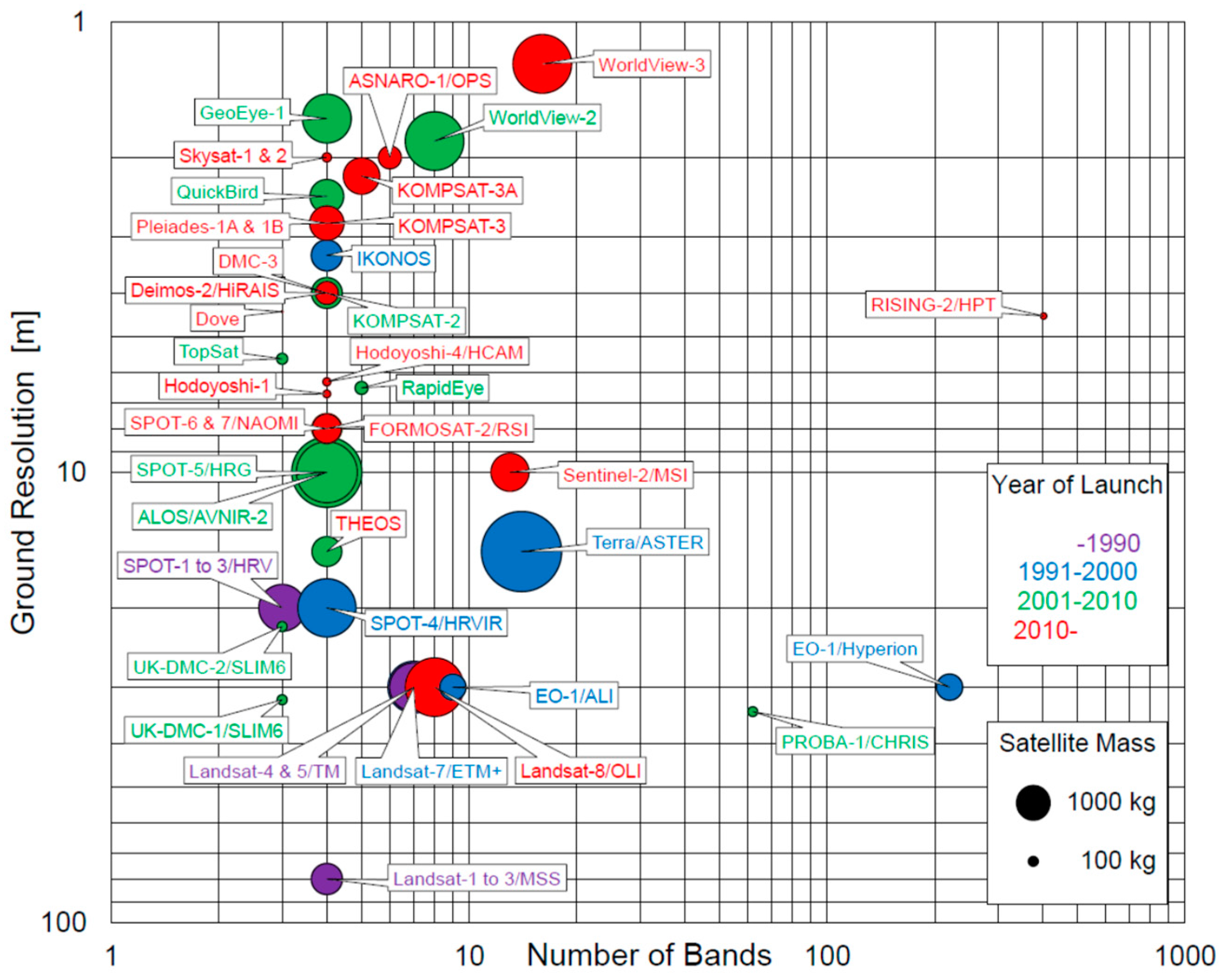
The development of the HPT commenced in 2010, with the aim of achieving a high spatial resolution sensor suitable for deployment on a microsatellite for Earth observation. Earth observation has diverse requirements regarding spatial and spectral resolutions according to different fields of application, e.g., agriculture, environmental monitoring, hydrology, and oceanography (cf. Figure 2 in [
2]). A multispectral sensor with 5-m spatial resolution can satisfy a wide range of these fields, except for intelligence services, traffic monitoring, and urban development purposes, which mostly require sub-meter resolution. Therefore, the goal of developing a 5-m-resolution multispectral sensor was envisioned for the HPT. In order to achieve a ground sample distance of 5 m with a pixel size of 7.4 μm from an altitude of 700 km, a focal length of 1 m is required for the optical system of the sensor. Considering the high SNR required for multispectral imaging, an aperture diameter of 100 mm is considered the largest possible for a 50-kg microsatellite. Accordingly, the diffraction-limited resolution on the focal plane of the optical system is 6.4 μm at the 500-nm wavelength. As the diffraction-limited resolution is close to the pixel size, a diffraction-limited optical system is required. This is why the name of the HPT sensor includes the word precision instead of the resolution.
The optical system of the HPT adopts a Cassegrain reflecting telescope that was designed and manufactured by Genesia Corp. (Mitaka, Japan). It is important in the design of an optical system for any spaceborne multispectral sensor to account for chromatic aberration and thermal stability. Compared with refracting telescopes using lenses, reflecting telescopes using mirrors have the advantage of no chromatic aberration, which is significant for wavelength scanning in a wide spectral range. Minimizing the chromatic aberration of a refracting telescope is possible, but balancing the chromatic aberration correction with thermal stabilization is usually difficult. The adoption of a reflecting telescope enables the development of the optical system to focus on thermal stability. In addition, the Cassegrain telescope comprises a parabolic primary mirror and a hyperbolic secondary mirror, which create the long focal length required for high spatial resolution imaging, while minimizing the length of the telescope tube by reflecting the light path. The telescope tube is made of carbon fiber-reinforced plastic, which has a very low coefficient of thermal expansion and high stiffness. The mirror is made from zero thermal expansion pore-free ceramics, which is a material developed by Nihon Ceratec Co., Ltd. (Sendai, Japan) for use in semiconductor manufacturing equipment. Although zero thermal expansion pore-free ceramics have an extremely low coefficient of thermal expansion at around room temperatures, active thermal control of the mirrors is impractical for the limited power supply of a microsatellite. Based on the results of thermal simulation analysis, both the tip of the telescope tube and the reverse side of the secondary mirror, which are exposed to the outside of the satellite, are covered by multilayer insulation to maintain the mirrors at room temperature passively. At room temperature, the Strehl ratio of the optical system measured with a laser interferometer is 0.92, which satisfies the criterion for a diffraction-limited system (>0.8).
A monochromatic CCD image sensor module is used for imaging in the four spectral bands. Generally, CCD image sensors consume more power, but are more sensitive than complementary metal oxide semiconductor (CMOS) image sensors. The most important characteristic of a CCD image sensor for satellite imaging is a global shutter that can capture the entire frame at the same instant, although many CMOS image sensors use a rolling shutter. The CCD module T065 manufactured by Watec Co., Ltd. (Tsuruoka, Japan) was developed originally for the optical mission payload instrumentation of the SPRITE-SAT. The unit cell size of this CCD module is 7.4 µm× 7.4 μm, and the effective image size is 659 × 494 pixels. The gain and exposure time of the CCD module are changeable from −6 to +36 dB and from 20 μs to 34 s, respectively, enabling the HPT to be applied to a wide range of spectral radiances on the Earth’s surface. An important function supported by this CCD module is the external trigger shutter that allows the synchronization of the three CCD modules for the blue, green, and red bands, in order to acquire a true color composite image.
In the HPT on the RISING-2 microsatellite, LCTF technology was applied for the first time to a spaceborne multispectral sensor through collaboration with the Research Institute for Advanced Liquid Crystal Technology at the Aomori Support Center for Industrial Promotion in Japan. The LCTF is a type of optical band pass filter that uses liquid crystal for the birefringent plates of the Lyot filter, and the LCTF technology has been used for many applications, e.g., agriculture, healthcare, archaeology, and art (see review by [
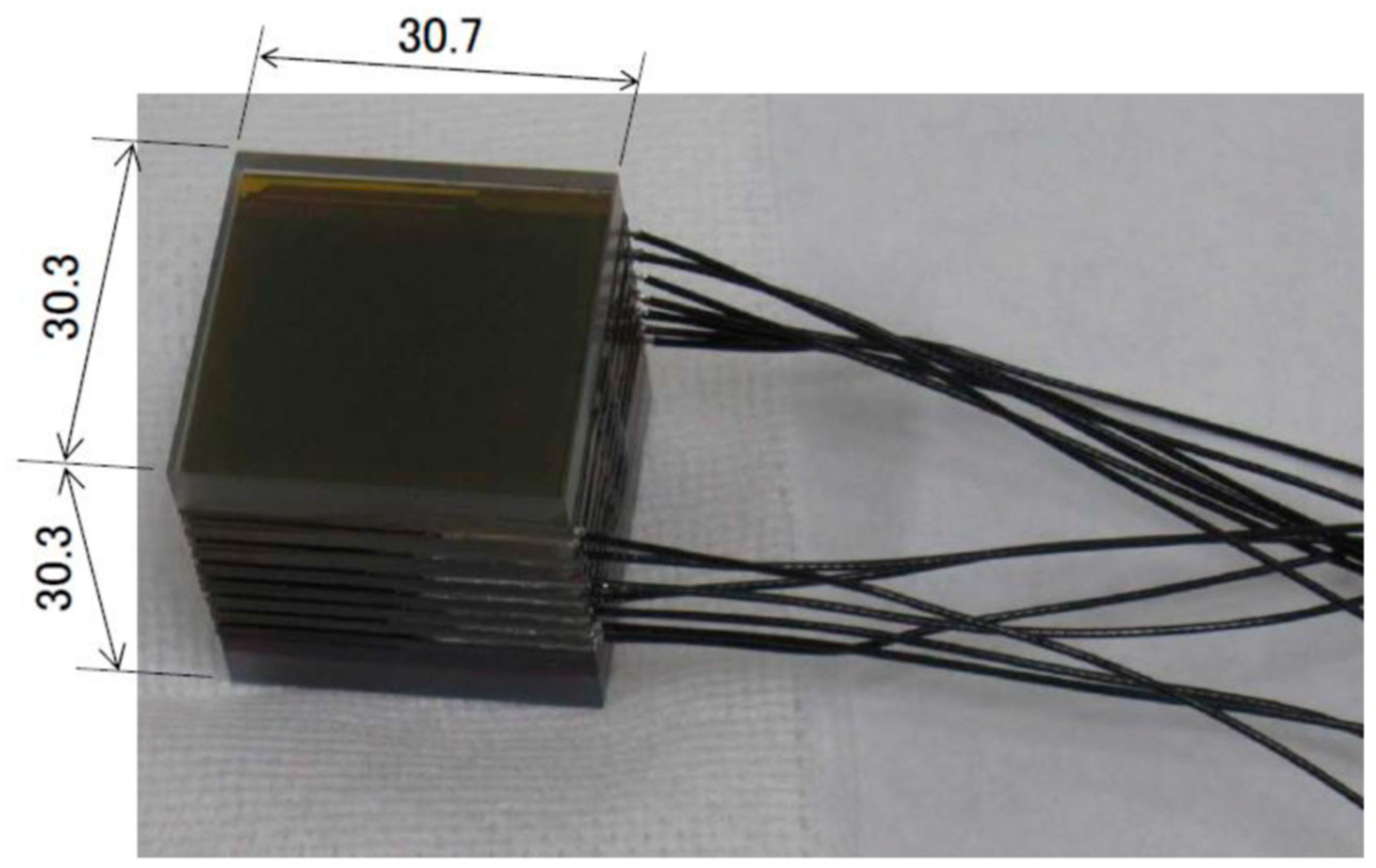
11] and references therein). The LCTF is composed of several stacked layers of liquid crystal sandwiched between crossed polarizers, and the transmission wavelength of the LCTF is controlled by square-wave voltages that are applied to each layer. On the RISING-2 microsatellite, the LCTF and the voltage-controlling circuit are separated into the HPT and the SHU, respectively. The LCTF developed for the HPT (
Figure 4) has dimensions of 30.7 mm × 30.3 mm × 30.3 mm, and it weighs 80 g. The power consumption of the voltage-controlling circuit is 0.2 W. These features enhance the compatibility of the LCTF technology with nano/microsatellites. The LCTF is used for wavelength scanning in the NIR band, and the central wavelength of the NIR band is electrically selectable at 1-nm intervals from 650 nm to 1050 nm. In terms of the number of spectral bands, the HPT has 401 bands in the NIR. The peak transmittance and the full width at half maximum increase with the central wavelength from 7% and 12 nm (at 650 nm) to 29% and 30 nm (at 1050 nm), respectively. To maintain the LCTF performance over a wide temperature range, a temperature sensor is attached to the LCTF, and the optimum voltages at the measured temperature are applied automatically using a look-up table stored in the voltage-controlling circuit. The response time for switching from one central wavelength to another depends on the temperature and on the combination of wavelengths. For example, the response time at 25 °C ranges from 39 ms (for a switch from 850 nm to 840 nm) to 259 ms (for a switch from 710 nm to 970 nm), and it is slower/faster at lower/higher temperatures, respectively. The exposure of the NIR CCD is designed to start after sufficient time has elapsed for the switching of the wavelengths.

 ,
, 


