Optical Fiber Magnetic Field Sensors Based on Magnetic Fluid: A Review

 ,
,  ,
,  ,
, 

Abstract
1. Introduction
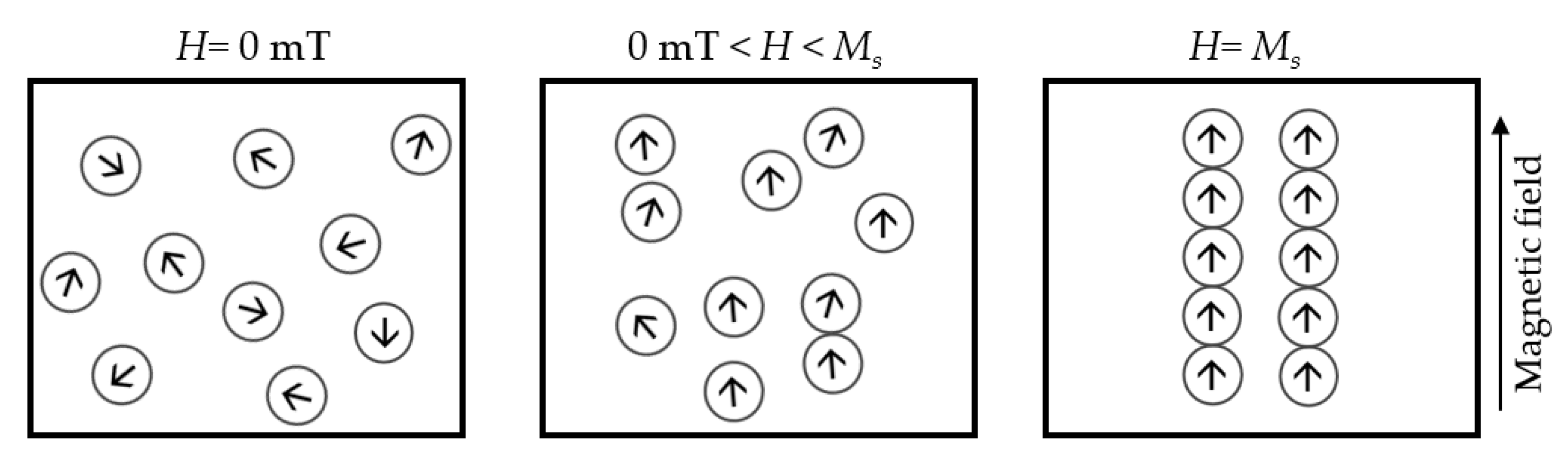
2. Magnetic Fluid
- (a)
- If E is perpendicular to H, , then the nMF will decrease with the magnetic field;
- (b)
- If E is parallel to H, , then the nMF will increase with the magnetic field.
3. Grating-Based Sensors
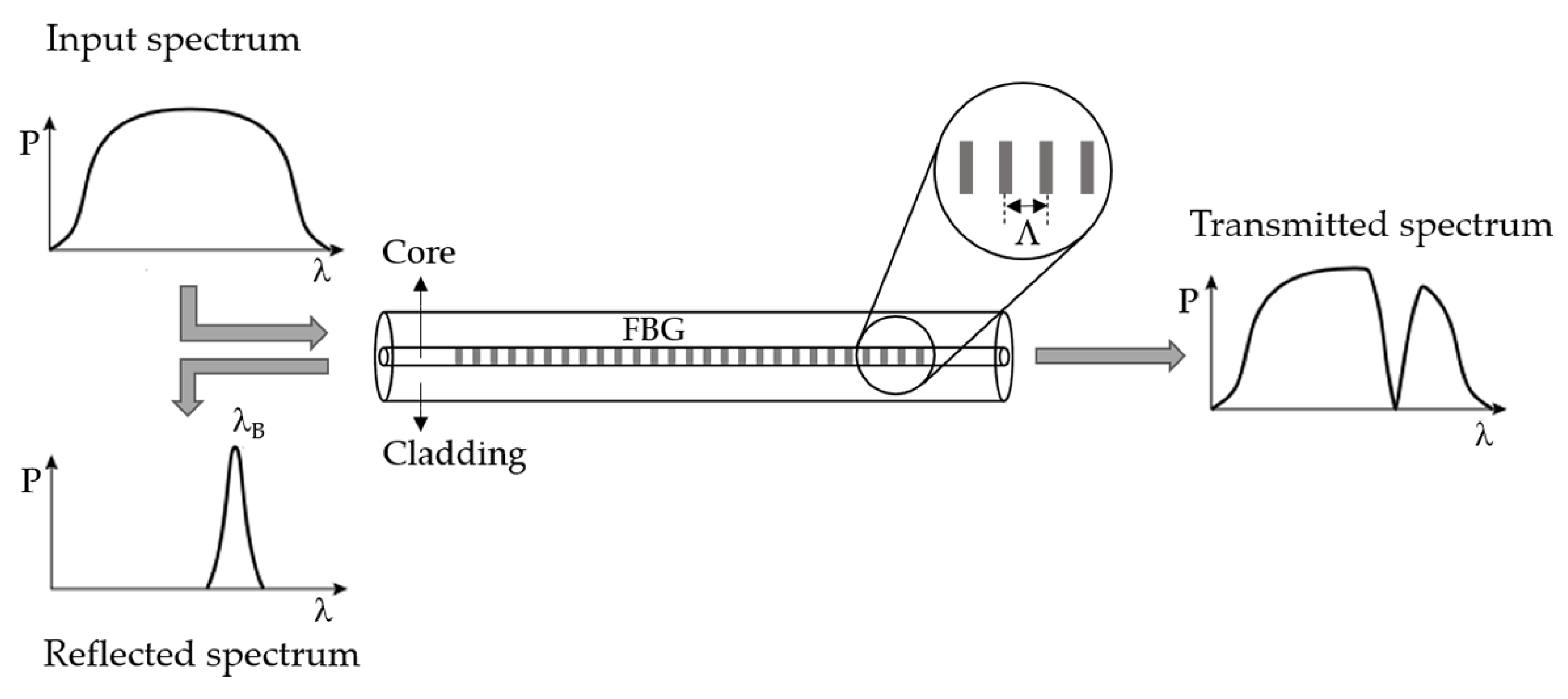
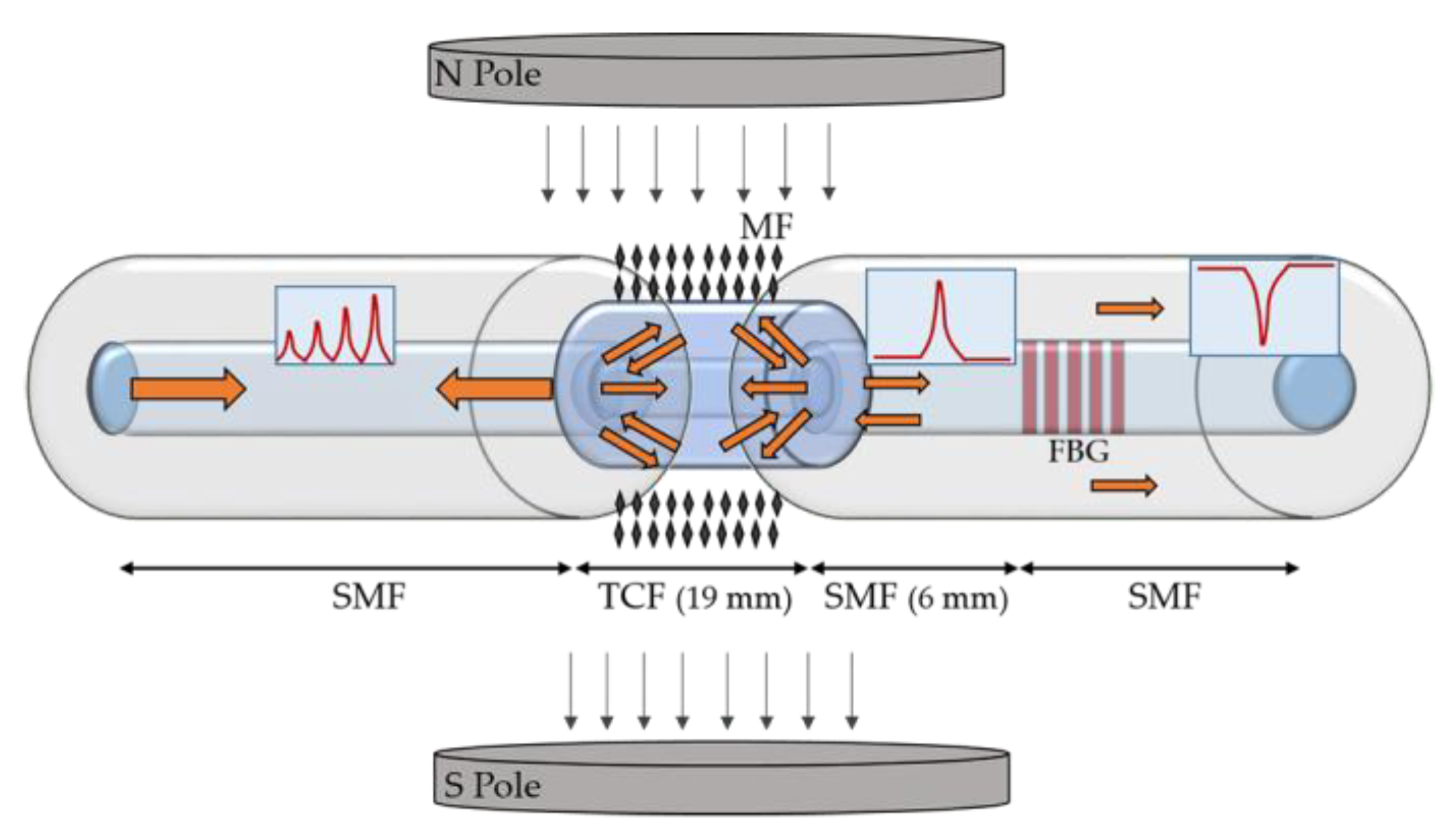
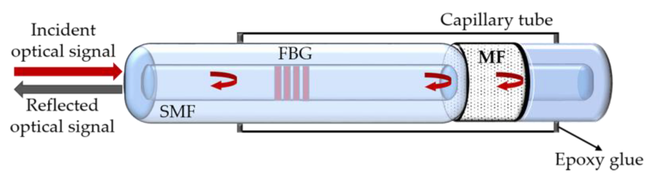
3.1. FBG-Based Sensors
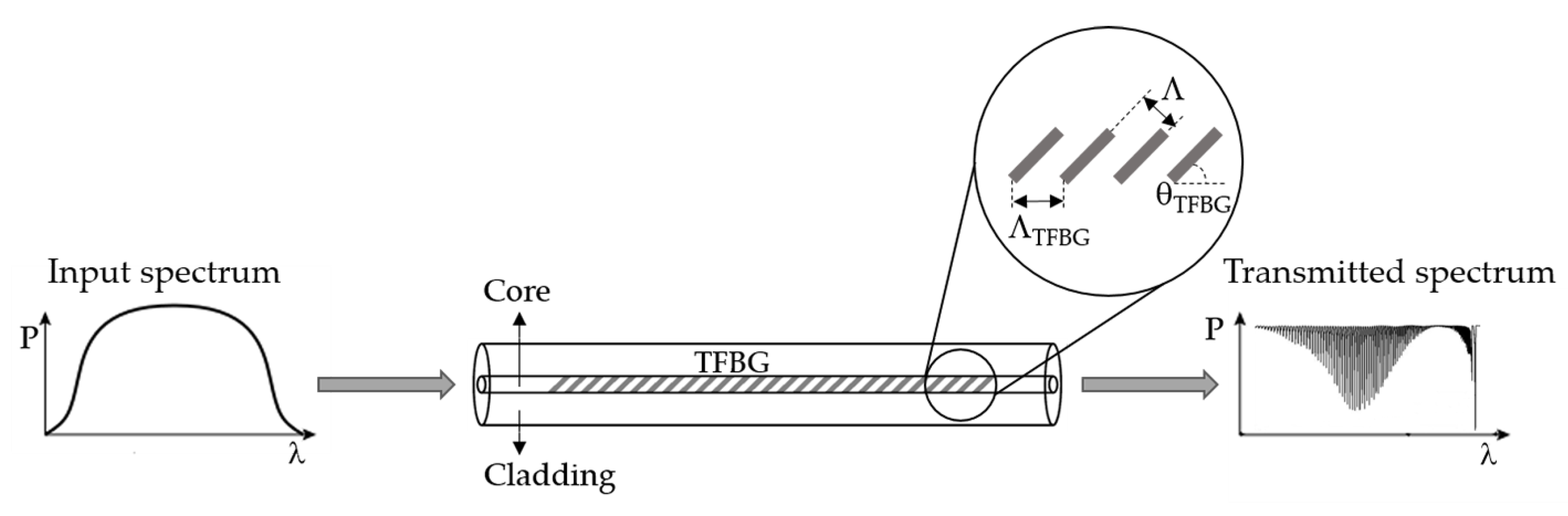
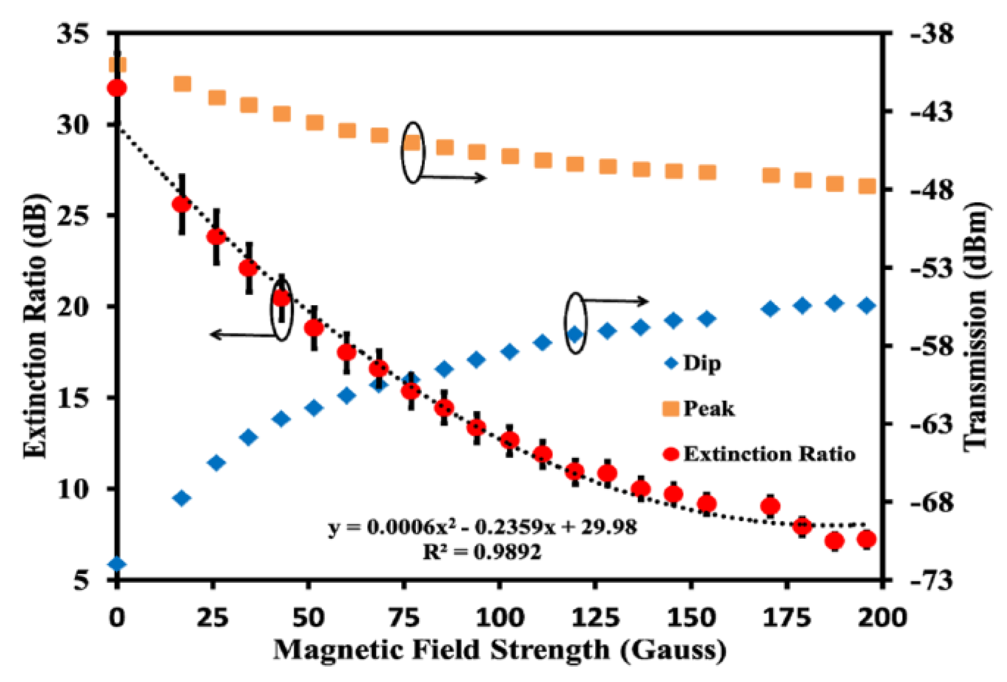
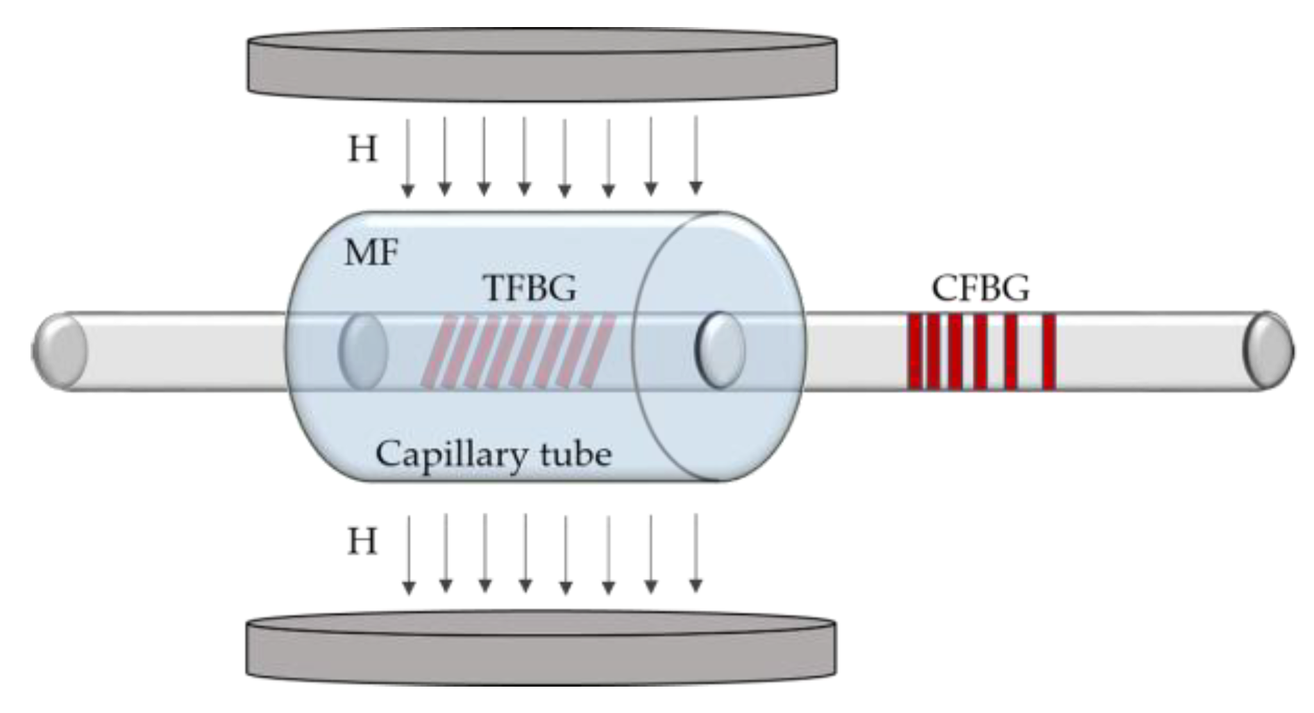
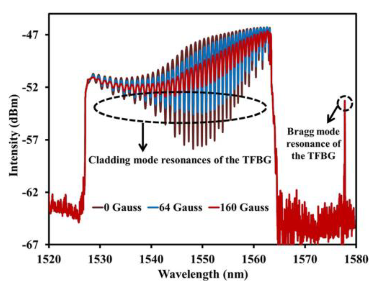
3.2. TFBG-Based Sensors
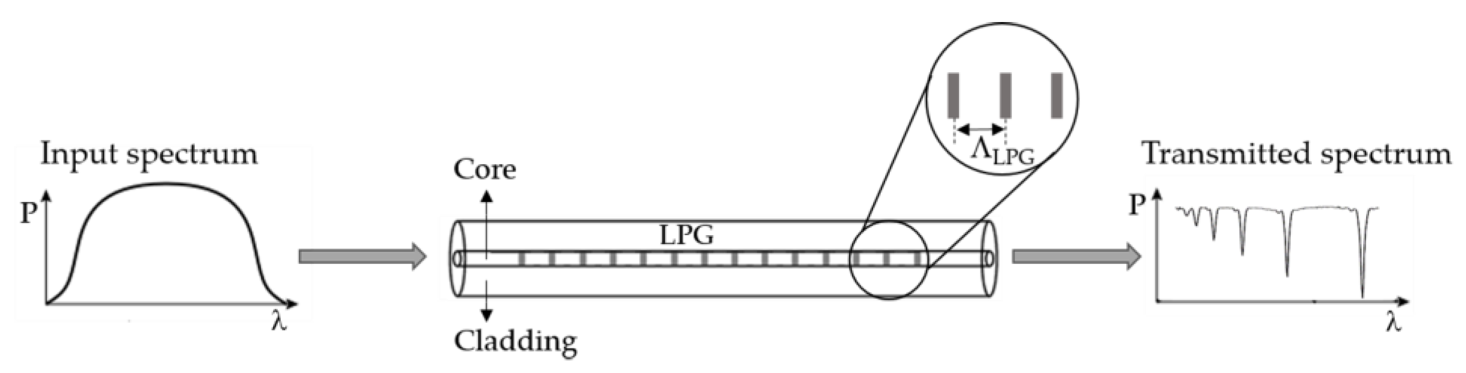
3.3. LPG-Based Sensors
4. Interferometric Sensors
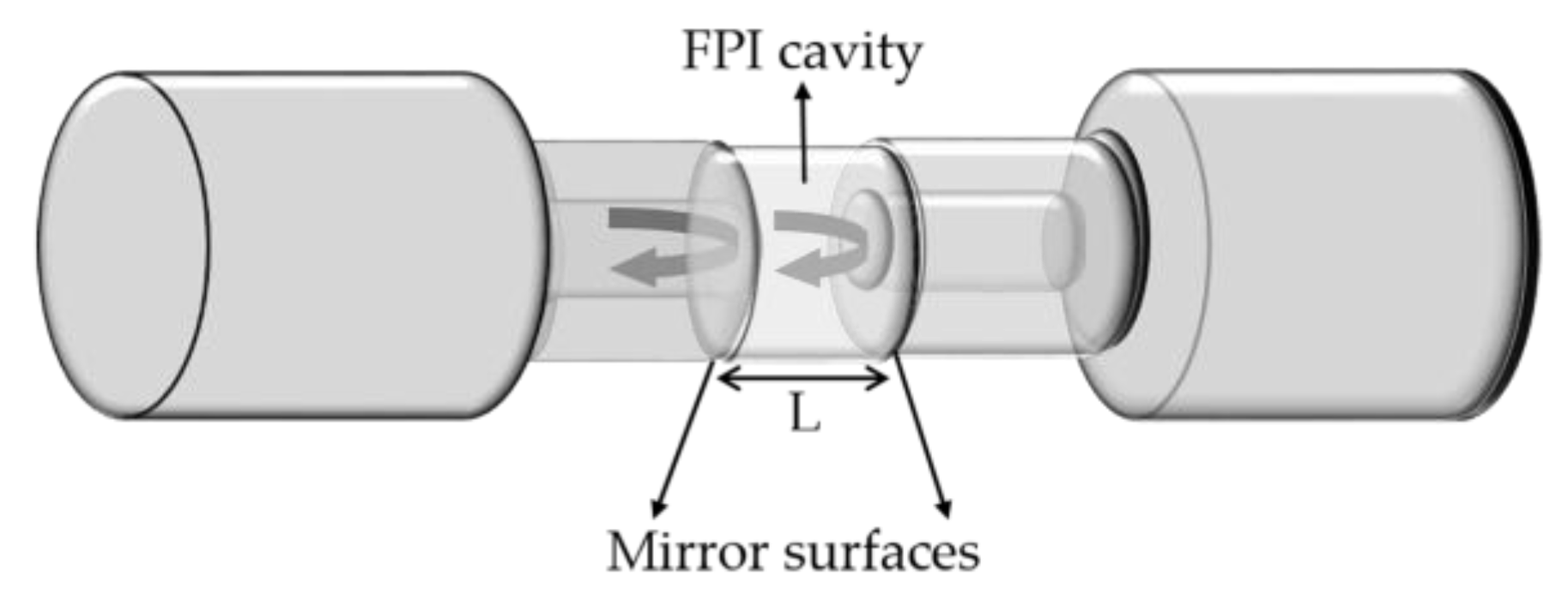
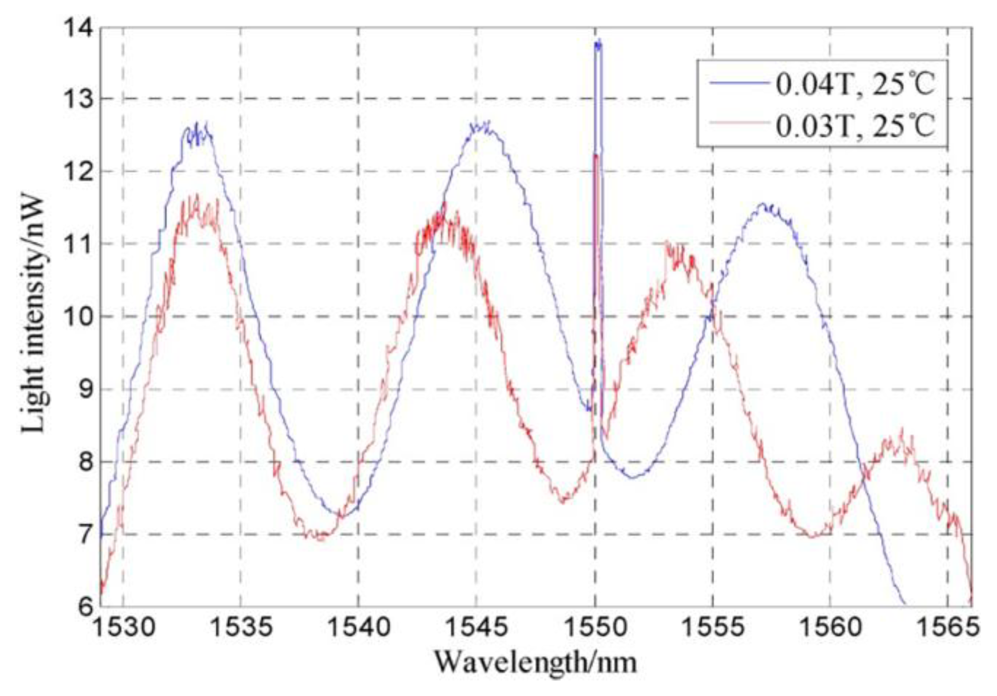
4.1. FPI-Based Sensors
4.2. MZI-Based Sensors
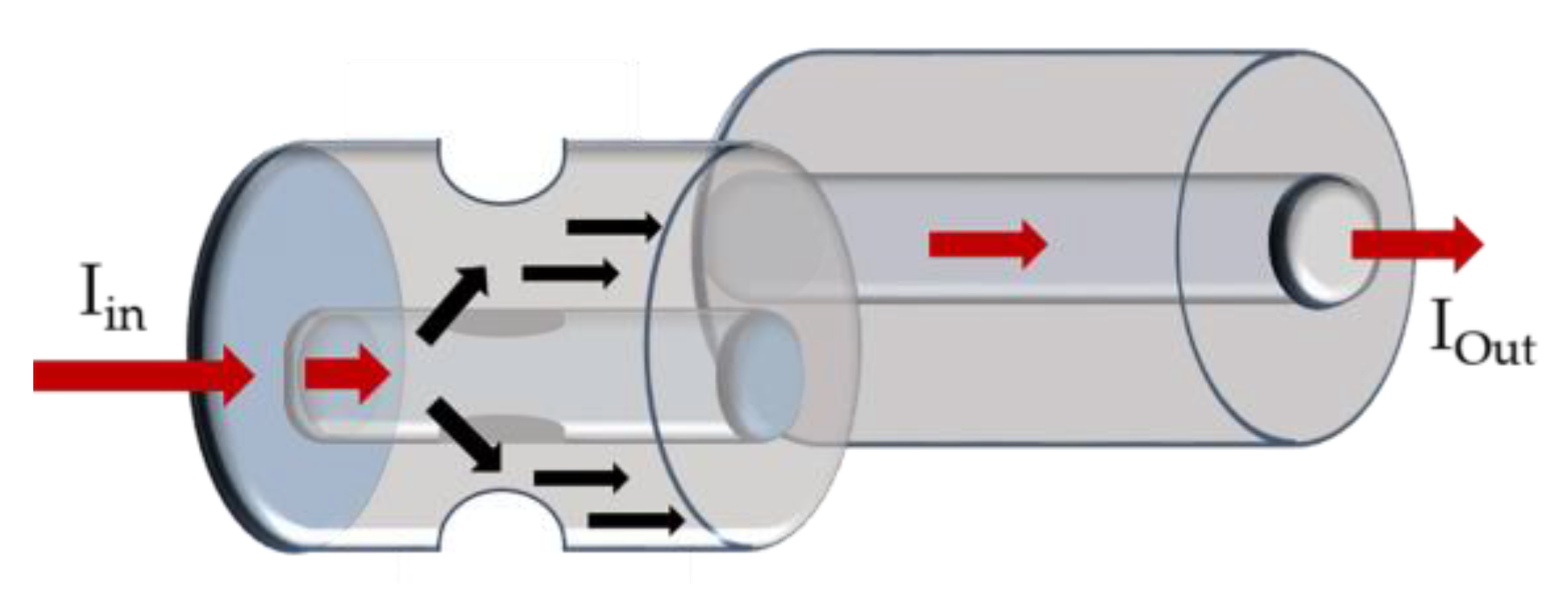
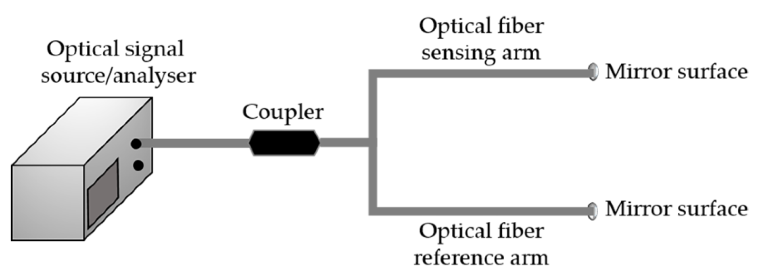
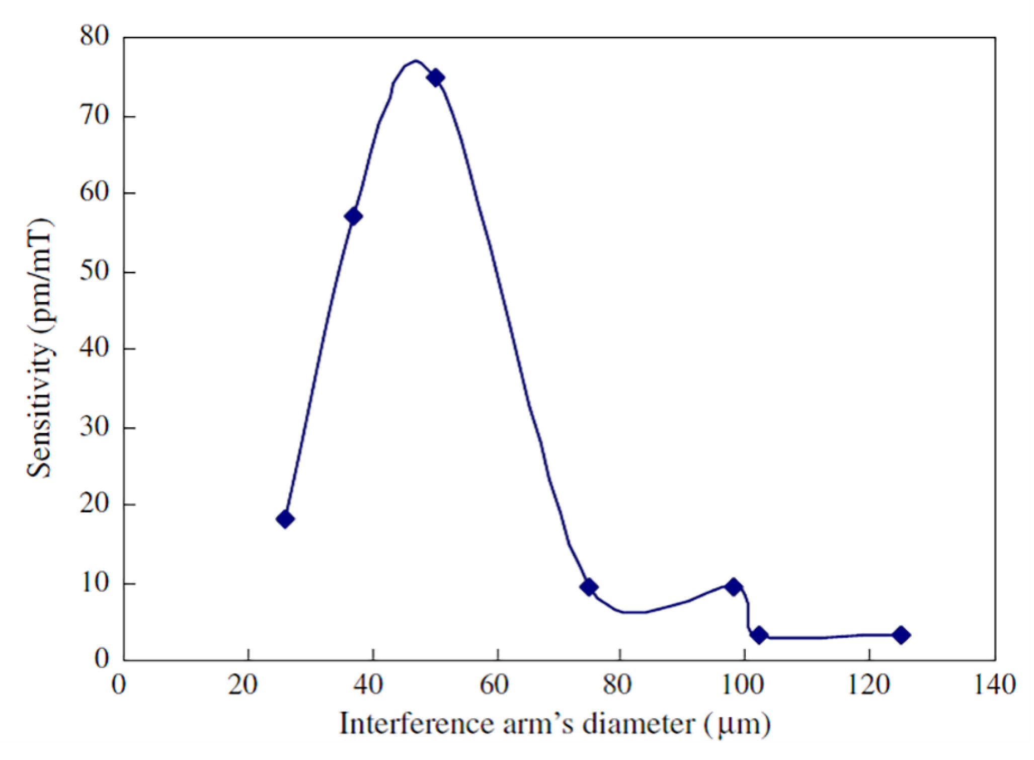
4.3. MI-Based Sensors
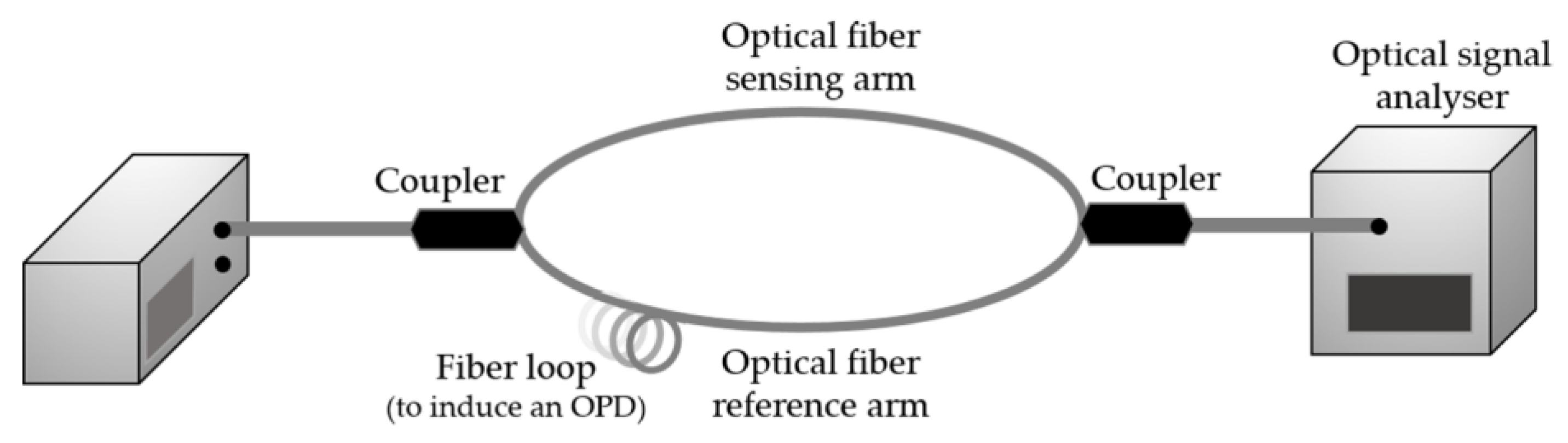
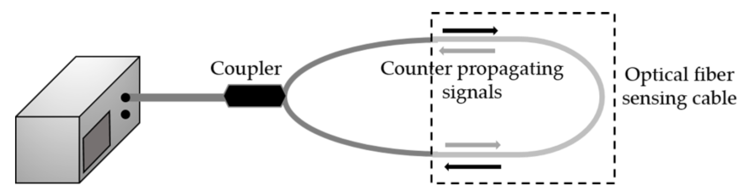
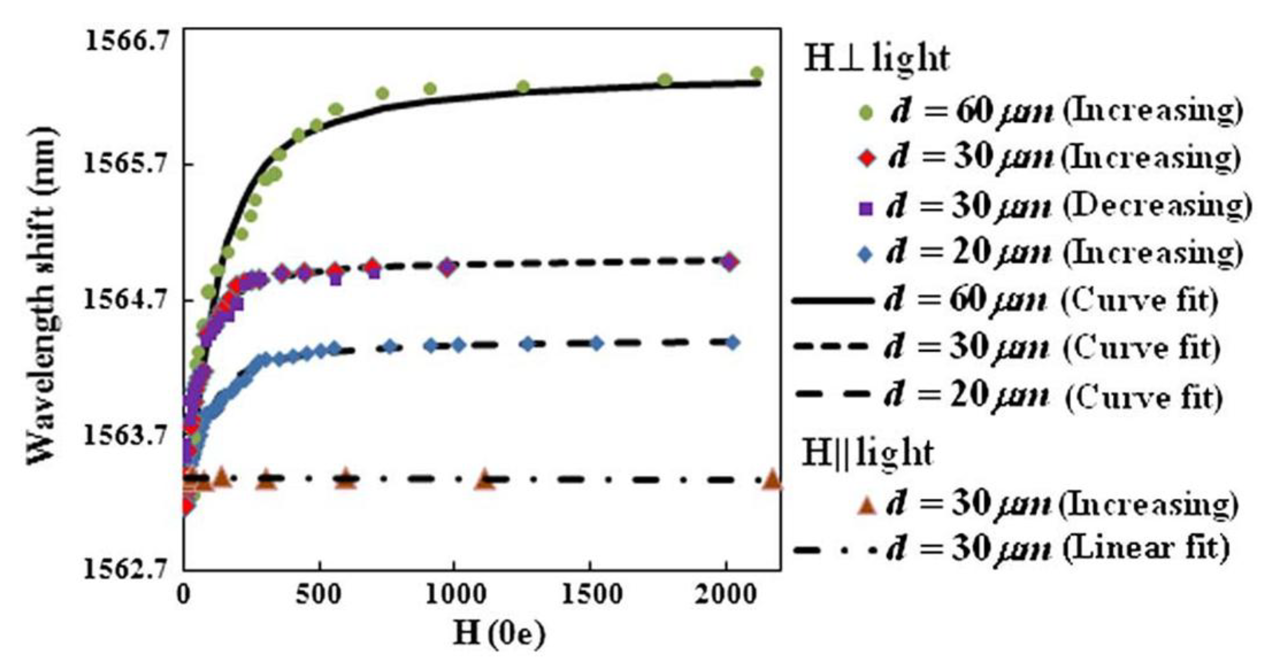
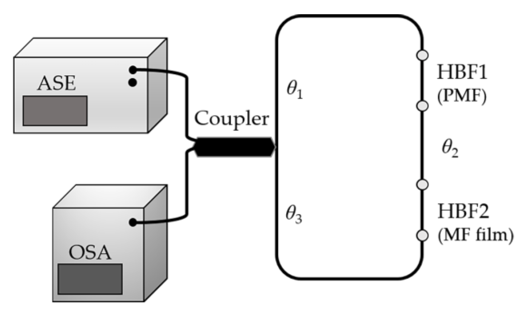
4.4. SI-Based Sensors
5. Other Sensing Schemes Based Sensors
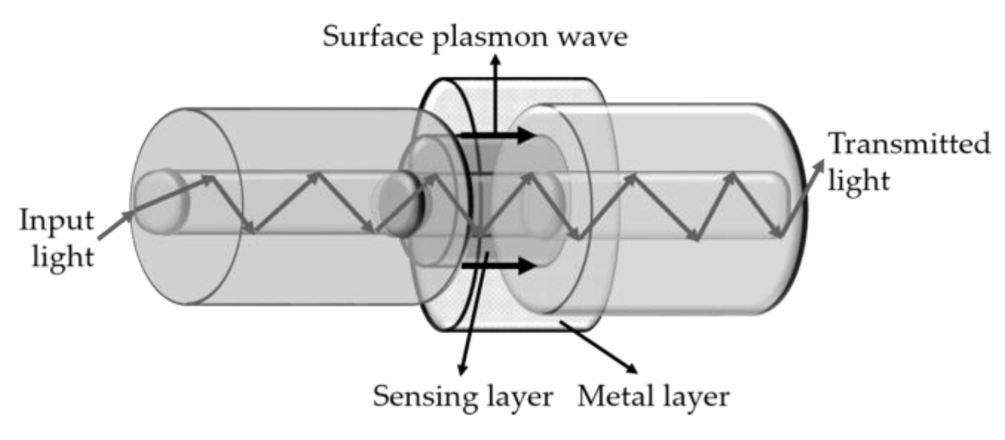
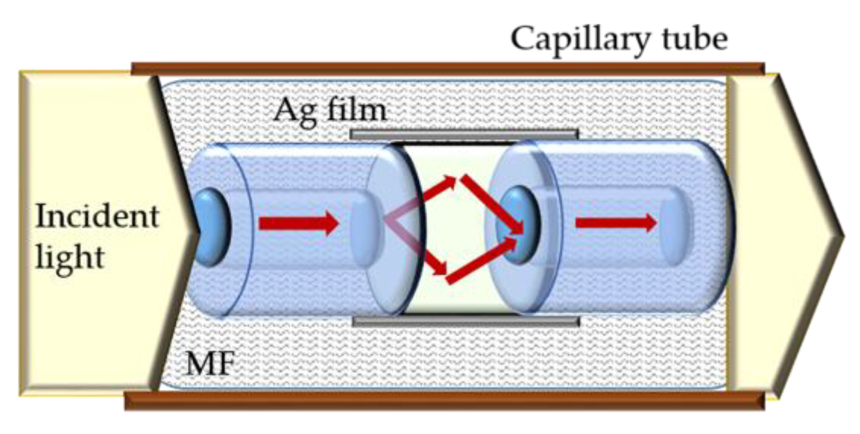
5.1. SPR-Based Sensors
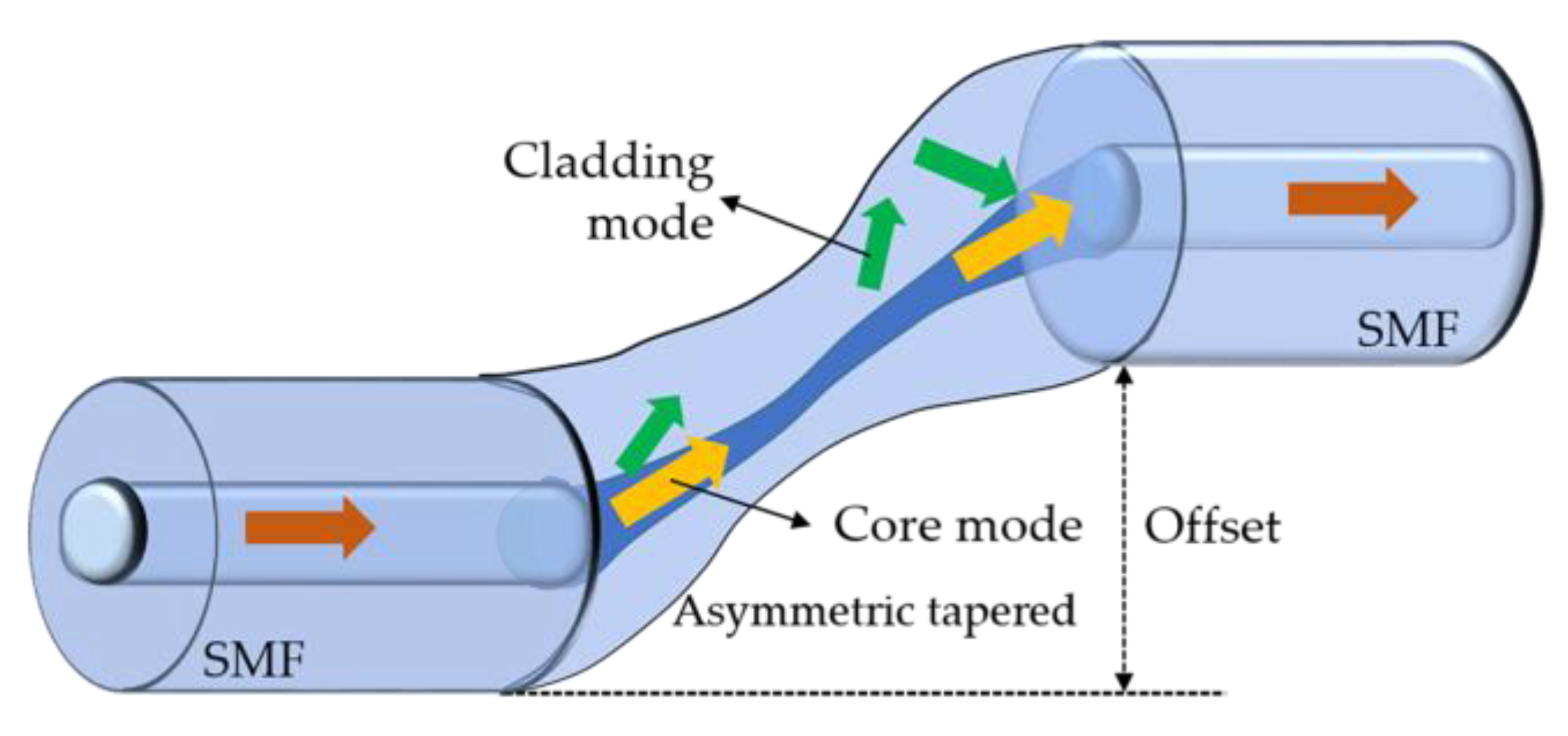
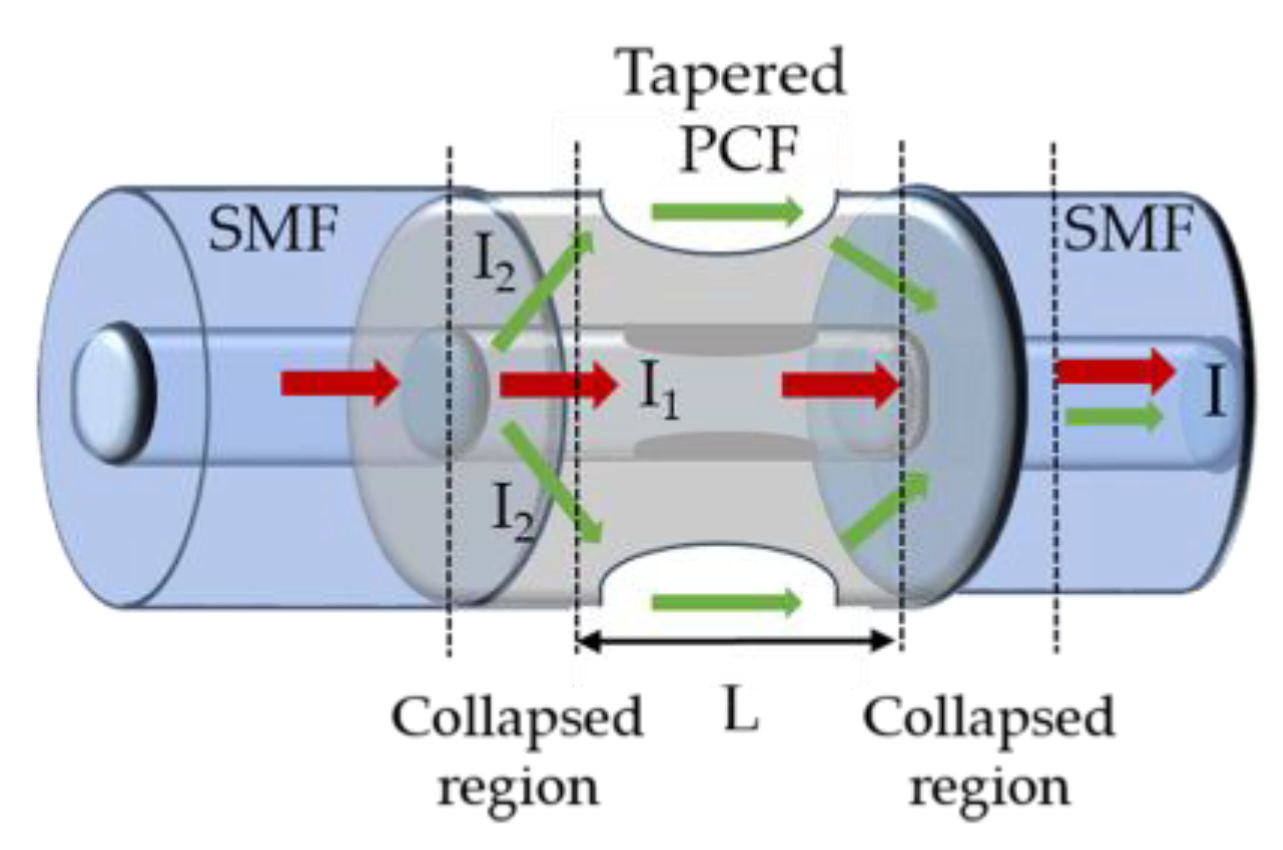
5.2. Etched, Tapered, U-Shaped Fibers
6. Final Remarks
Author Contributions
Funding
Conflicts of Interest
Appendix A
| Acronym | Definition |
| B | Birefringent coefficient |
| CCMI | Core cladding mode interferometer |
| CFBG | Chirped fiber Bragg grating |
| CWD | Coupling wavelength dip |
| DLUWT | Doubly-deposited uniform waist tapered fiber |
| E | Electric field |
| eFBG | Etched fiber Bragg grating |
| FBG | Uniform fiber Bragg grating |
| FEM | Finite element method |
| FLRDS | Fiber loop ring-down spectroscopy |
| FPI | Fabry-Perot interferometer |
| H | Magnetic field |
| HBF | High birefringence fiber |
| HB-PCF | High birefringence photonic crystal fiber |
| Hc | Critical magnetic field |
| HC-PCF | Hollow-core photonic crystal fiber |
| LFPI | Cavity length (FPI) |
| LPG | Long period grating |
| LSI | Length of the polarized sensing path |
| MF | Magnetic fluid |
| MI | Michelson interferometer |
| MMF | Multimode fiber |
| MNF | No-core fiber fused between two multimode fibers |
| MOF | Micro-structured optical fiber |
| Ms | Saturation magnetization |
| MZI | Mach-Zehnder interferometer |
| n | Refractive index of the material present in the cavity (FPI) |
| NCF | No-core fiber |
| ncore | Effective refractive index of the core mode (LPG) |
| Effective refractive index of the ith cladding mode (TFBG) | |
| neff | Effective refractive index of the propagate core mode (FBG) |
| Refractive index of the ith cladding mode at (TFBG) | |
| Refractive index of the core mode at λTFBG (TFBG) | |
| Refractive index of the core mode at (TFBG) | |
| nfast | Effective refractive index of the fast mode (SI) |
| nMF | Refractive index of the magnetic fluid |
| ns | Saturated value of the refractive index of the MF |
| nslow | Effective refractive index of the slow mode (SI) |
| n0 | Refractive index of the magnetic fluid under magnetic field lower than critical magnetic field |
| OPD | Optical path difference (MZI) |
| PCF | Photonic crystal fiber |
| PMF | Polarization maintaining fiber |
| PML | Perfectly matched layer |
| PS | Phase shift |
| RIMC | Refractive index matched coupling |
| SI | Sagnac interferometer |
| SMF | Single mode fiber |
| SMS | Single mode-multi mode-single mode |
| SNS | Single mode-no-core-single mode |
| SPR | Surface plasmon resonance |
| T | Temperature |
| TCF | Thin core fiber |
| TFBG | Tilted fiber Bragg grating |
| UV | Ultraviolet |
| α | Fitting parameter (Langevin function) |
| εMF | Dielectric constant of the magnetic fluid |
| Tilt angle of the grating planes related to the perpendicular of the fiber axis (TFBG) | |
| θ1 | Angle between the polarization direction of counterpropagating beams and the corresponding fast axes of two HBF sections (SI) |
| θ2 | Angle between the fast axes of the two HBF sections (SI) |
| θ3 | Angle between the polarization direction of counterpropagating beams and the corresponding fast axes of two HBF sections (SI) |
| λ | Optical signal wavelength |
| λB | Reflected Bragg wavelength (FBG) |
| λi | Center wavelength of the ith attenuation band |
| λTFBG | Resonance wavelength of the core mode (TFBG) |
| Resonance wavelength of the ith cladding mode (TFBG) | |
| Λ | Grating period (FBG) |
| ΛFPI | Spectral modulation period (FPI) |
| Grating period (LPG) | |
| ΛTFBG | Grating period along the axis fiber (TFBG) |
| φFPI | Phase of the reflected optical signal (FPI) |
| φSI | Phase (SI) |
| χ | Electric susceptibility |
References
- Shi, D.; Sadat, E.; Dunn, A.; Mast, D. Photo-fluorescent and magnetic properties of iron oxide nanoparticles for biomedical applications. Nanoscale 2015, 7, 8209–8232. [Google Scholar] [CrossRef] [PubMed]
- Toghraie, D.; Alempour, S.; Afrand, M. Experimental determination of viscosity of water based magnetite nanofluid for application in heating and cooling systems. J. Magn. Magn. Mater. 2016, 417, 243–248. [Google Scholar] [CrossRef]
- Nemec, F.; Morgan, D.; Gurnett, D.; Andrews, D. Empirical model of the Martian dayside ionosphere: Effects of crustalmagnetic fields and solar ionizing flux at higher altitudes. J. Geophys. Res. Space Phys. 2016, 121, 1760–1771. [Google Scholar] [CrossRef]
- Tolman, E.; Hughes, J.; Wolfe, S.; Wukitch, S.; LaBombard, B.; Hubbard, A.; Marmar, E.; Snyder, P.; Schmidtmayr, M. Influence of high magnetic field on access to stationary H-modes and pedestal characteristics in Alcator C-Mo. Nucl. Fusion 2018, 58, 046004. [Google Scholar] [CrossRef]
- Mancoff, F.; Dunn, J.; Clemens, B.; White, R. A giant magnetoresistance sensor for high magnetic field measurements. Appl. Phys. Lett. 2000, 77, 1879–1881. [Google Scholar] [CrossRef]
- Dang, H.; Maloof, A.; Romalis, M. Ultrahigh sensitivity magnetic field and magnetization measurements with an atomic magnetometer. Appl. Phys. Lett. 2010, 97, 151110. [Google Scholar] [CrossRef]
- Langfelder, G.; Tocchio, A. Operation of Lorentz-force MEMS Magnetometers with a frequency offset between driving current and mechanical resonance. IEEE Trans. Magn. 2014, 50, 4700106. [Google Scholar] [CrossRef]
- Snoeij, M.; Schaffer, V.; Udayashankar, S.; Ivanov, M. Integrated fluxgate magnetometer for use in isolated current sensing. IEEE J. Solid State Circuits 2016, 51, 1684–1694. [Google Scholar] [CrossRef]
- Lenz, J.; Edelstein, A. Magnetic sensors and their applications. IEEE Sens. J. 2006, 6, 631–649. [Google Scholar] [CrossRef]
- Ripka, P.; Janošek, M. Advances in magnetic field sensors. IEEE Sens. J. 2010, 10, 1108–1116. [Google Scholar] [CrossRef]
- Wang, Y.; Li, J.; Viehland, D. Magnetoelectrics for magnetic sensor applications: Status, challenges and perspectives. Mater. Today 2014, 17, 269–275. [Google Scholar] [CrossRef]
- Sun, L.; Jiang, S.; Marciante, J. All-fiber optical magnetic-field sensor based on Faraday rotation in highly terbium-doped fiber. Opt. Express 2010, 18, 5407–5412. [Google Scholar] [CrossRef]
- Cheng, L.; Han, J.; Jin, L.; Guo, Z.; Guan, B.-O. Sensitivity enhancement of Faraday effect based heterodyning fiber laser magnetic field sensor by lowering linear birefringence. Opt. Express 2013, 21, 30156–30162. [Google Scholar] [CrossRef]
- Yang, M.; Dai, J.; Zhou, C.; Desheng, J. Optical fiber magnetic field sensors with TbDyFe magnetostrictive thin films as sensing materials. Opt. Express 2009, 17, 20777–20782. [Google Scholar] [CrossRef]
- Liu, H.; Or, S.; Tam, H. Magnetostrictive composite–fiber Bragg grating (MC–FBG) magnetic field sensor. Sens. Actuators A Phys. 2012, 173, 122–126. [Google Scholar] [CrossRef]
- Ding, G.; Zhang, S.; Cao, H.; Gao, B.; Zhang, B. Flux density measurement of radial magnetic bearing with a rotating rotor based on fiber Bragg grating-giant magnetostrictive material sensors. Appl. Opt. 2017, 56, 4975–4981. [Google Scholar] [CrossRef]
- Chieh, J.; Yang, S.; Horng, H.; Hong, C.-Y.; Yang, H. Magnetic-fluid optical-fiber modulators via magnetic modulation. Appl. Phys. Lett. 2007, 90, 133505. [Google Scholar] [CrossRef]
- Horng, H.; Chen, C.; Fang, K.; Yang, S.; Chieh, J.; Hong, C.-Y.; Yan, H. Tunable optical switch using magnetic fluids. Appl. Phys. Lett. 2004, 85, 5592. [Google Scholar] [CrossRef]
- Tagoudi, E.; Milenko, K.; Pissadakis, S. Intercore coupling effects in multicore optical fiber tapers using magnetic fluid out-claddings. J. Lightw. Technol. 2016, 34, 5561–5565. [Google Scholar] [CrossRef]
- Candiani, A.; Margulis, W.; Sterner, C.; Konstantaki, M.; Pissadakis, S. Phase-shifted Bragg microstructured optical fiber gratings utilizing infiltrated ferrofluids. Opt. Lett. 2011, 36, 2548–2550. [Google Scholar] [CrossRef]
- Chen, L.; Huang, X.; Zhu, J.; Li, G.; Lan, S. Fiber magnetic-field sensor based on nanoparticle magnetic fluid and Fresnel reflection. Opt. Lett. 2011, 36, 2761–2763. [Google Scholar] [CrossRef]
- Li, X.; Dind, H. All-fiber magnetic-field sensor based on microfiber knot resonator and magnetic fluid. Opt. Lett. 2012, 37, 5187–5189. [Google Scholar] [CrossRef]
- Jiles, D.; Atherton, D. Theory of ferromagnetic hysteresis. J. Magn. Magn. Mater. 1986, 61, 48–60. [Google Scholar] [CrossRef]
- Martinez, L.; Cecelja, F.; Rakowski, R. A novel magneto-optic ferrofluid material for sensor applications. Sens. Actuators A Phys. 2005, 123–124, 438–443. [Google Scholar] [CrossRef]
- Yang, S.; Chieh, J.; Horng, H.; Hong, C.-Y.; Yang, H. Origin and applications of magnetically tunable refractive index of magnetic fluid films. Appl. Phys. Lett. 2004, 84, 5204–5206. [Google Scholar] [CrossRef]
- Yang, S.; Chen, Y.; Horng, H.; Hong, C.-Y.; Tse, W.; Yang, H. Magnetically-modulated refractive index of magnetic fluid films. Appl. Phys. Lett. 2002, 81, 4931–4933. [Google Scholar] [CrossRef]
- Horng, H.; Hong, C.-H.; Yang, S.; Yang, H. Designing the refractive indices by using magnetic fluids. Appl. Phys. Lett. 2003, 82, 2434–3436. [Google Scholar] [CrossRef]
- Chen, Y.; Yang, S.; Tse, W.; Horng, H.; Hong, C.-Y.; Yang, H. Thermal effect on the field-dependent refractive index of the magnetic fluid film. Appl. Phys. Lett. 2003, 82, 3481–3483. [Google Scholar] [CrossRef]
- Liu, T.; Chen, X.; Di, Z.; Zhang, J. Tunable magneto-optical wavelength filter of long-period fiber grating with magnetic fluids. Appl. Phys. Lett. 2007, 91, 121116. [Google Scholar] [CrossRef]
- Mailfert, A.; Nahounou, B. Dielectric behavior of a ferrofluid. IEEE Trans. Magn. 1980, 16, 254–257. [Google Scholar] [CrossRef]
- Zhao, Y.; Wu, D.; Lv, R.-Q.; Ying, Y. Tunable characteristics and mechanism analysis of the magnetic fluid refractive index with applied magnetic field. IEEE Trans. Magn. 2014, 50, 4600205. [Google Scholar] [CrossRef]
- Othonos, A. Fiber Bragg gratings. Rev. Sci. Instrum. 1997, 68, 4309–4341. [Google Scholar] [CrossRef]
- Dai, J.; Yang, M.; Li, X.; Liu, H.; Tong, X. Magnetic field sensor based on magnetic fluid clad etched fiber Bragg grating. Opt. Fiber Technol. 2011, 17, 210–213. [Google Scholar] [CrossRef]
- Tian, Q.; Feng, Z.; Rong, Q.; Wan, Y.; Qiao, X.; Hu, M.; Yang, H.; Wang, R.; Shao, Z.; Yang, T. A temperature-independent fibre-optic magnetic-field sensor using thin-core fibre tailored fibre Bragg grating. Opt. Commun. 2017, 393, 169–172. [Google Scholar] [CrossRef]
- Yang, J.; Dong, X.; Zheng, Y.; Ni, K.; Chan, C.; Shum, P. Magnetic field sensing with reflectivity ratio measurement of fiber Bragg grating. IEEE Sens. J. 2015, 15, 1372–1376. [Google Scholar] [CrossRef]
- Erdogan, T.; Sipe, J. Tilted fiber phase gratings. J. Opt. Soc. Am. A 1996, 13, 296–313. [Google Scholar] [CrossRef]
- Childs, P.; Candiani, A.; Pissadakis, S. Optical fiber cladding ring magnetic field sensor. IEEE Photonics Technol. Lett. 2011, 23, 929–931. [Google Scholar] [CrossRef]
- Zheng, J.; Dong, X.; Zu, P.; Shao, L.-Y.; Chan, C.; Cui, Y.; Shum, P. Magnetic field sensor using tilted fiber grating interacting with magnetic fluid. Opt. Express 2013, 21, 17863–17868. [Google Scholar] [CrossRef]
- Zheng, J.; Dong, X.; Zu, P.; Ji, J.; Su, H. Intensity-modulated magnetic field sensor based on magnetic fluid and optical fiber gratings. Appl. Phys. Lett. 2013, 103, 183511. [Google Scholar] [CrossRef]
- Yang, D.; Du, L.; Xu, Z.; Jiang, Y.; Xu, J.; Wang, M.; Bai, Y.; Wang, H. Magnetic field sensing based on tilted fiber Bragg grating coated with nanoparticle magnetic fluid. Appl. Phys. Lett. 2014, 104, 061903. [Google Scholar] [CrossRef]
- Vengsarkar, A.; Lemaire, P.; Judkins, J.; Bhatia, V.; Erdogan, T.; Sipe, J. Long-period fiber gratings as band-rejection filters. J. Lightw. Technol. 1996, 14, 58–65. [Google Scholar] [CrossRef]
- Miao, Y.; Zhang, K.; Liu, B.; Lin, W.; Zhang, H.; Lu, Y.; Yao, J. Ferrofluid-infiltrated microstructured optical fiber long-period grating. IEEE Photonics Technol. Lett. 2013, 25, 306–309. [Google Scholar] [CrossRef]
- Tang, J.; Pu, S.; Luo, L.; Dong, S. Simultaneous measurement of magnetic field and temperature based on magnetic fluid-clad long period fiber grating. J. Eur. Opt. Soc. Rapid Publ. 2015, 10, 15025. [Google Scholar] [CrossRef]
- Yin, S.; Ruffin, P.B.; Yu, F. Fiber Optic Sensors, 2nd ed.; CRC Press Taylor & Francis Group: Boca Raton, FL, USA, 2008. [Google Scholar]
- Liao, C.; Hu, T.; Wang, D. Optical fiber Fabry-Perot interferometer cavity fabricated by femtosecond laser micromachining and fusion splicing for refractive index sensing. Opt. Express 2012, 20, 22813–22818. [Google Scholar] [CrossRef]
- Antunes, P.; Domingues, M.F.; Alberto, N.; André, P. Optical fiber microcavity strain sensors produced by the catastrophic fuse effect. IEEE Photonic Technol. Lett. 2014, 26, 78–81. [Google Scholar] [CrossRef]
- Alberto, N.; Tavares, C.; Domingues, M.F.; Correia, S.; Marques, C.; Antunes, P.; Pinto, J.L. Relative humidity sensing using micro-cavities produced by the catastrophic fuse effect. Opt. Quantum Electron. 2016, 48, 1–8. [Google Scholar] [CrossRef]
- Domingues, M.F.; Rodriguez, C.; Martins, J.; Tavares, C.; Marques, C.; Alberto, N.; André, P.; Antunes, P. Cost-effective optical fiber pressure sensor based on intrinsic Fabry-Perot interferometric micro-cavities. Opt. Fiber Technol. 2018, 42, 56–62. [Google Scholar] [CrossRef]
- Zhao, Y.; Lv, R.-Q.; Ying, Y.; Wang, Q. Hollow-core photonic crystal fiber Fabry-Perot sensor for magnetic field measurement based on magnetic fluid. Opt. Laser Technol. 2012, 44, 899–902. [Google Scholar] [CrossRef]
- Lv, R.-Q.; Zhao, Y.; Wang, D.; Wang, Q. Magnetic fluid-filled optical fiber Fabry-Perót sensor for magnetic field measurement. IEEE Photonic Technol. Lett. 2014, 26, 217–219. [Google Scholar] [CrossRef]
- Zhao, Y.; Lv, R.-Q.; Wang, D.; Wang, Q. Fiber optic Fabry-Perot magnetic field sensor with temperature compensation using a fiber Bragg grating. IEEE Trans. Instrum. Meas. 2014, 63, 2210–2214. [Google Scholar] [CrossRef]
- Xia, J.; Wang, F.; Luo, H.; Wang, Q.; Xiong, S. A magnetic field sensor based on a magnetic fluid-filled FP-FBG structure. Sensors 2016, 15, 620. [Google Scholar] [CrossRef]
- Nguyen, L.; Hwang, D.; Moon, S.; Moon, D.; Chung, Y. High temperature fiber sensor with high sensitivity based on core diameter mismatch. Opt. Express 2008, 16, 11369–11375. [Google Scholar] [CrossRef]
- Lee, B.; Kim, Y.; Park, K.; Eom, J.; Kim, M.; Rho, B.; Choi, H. Interferometric fiber optic sensors. Sensors 2012, 12, 2467–2486. [Google Scholar] [CrossRef]
- Zu, P.; Chang, C.; Lew, W.; Hu, L.; Jin, Y.; Liew, H.; Wong, W.; Dong, X. Temperature-insensitive magnetic field sensor based on nanoparticle magnetic fluid and photonic crystal fiber. IEEE Photonic J. 2012, 4, 491–498. [Google Scholar]
- Wu, J.; Miao, Y.; Lin, W.; Song, B.; Zhang, K.; Zhang, H.; Liu, B.; Yao, J. Magnetic-field sensor based on core-offset tapered optical fiber and magnetic fluid. J. Opt. 2014, 16, 075705. [Google Scholar] [CrossRef]
- Li, X.-G.; Zhou, X.; Zhao, Y.; Lv, R.-Q. Multi-modes interferometer for magnetic field and temperature measurement using photonic crystal fiber filled with magnetic fluid. Opt. Fiber Technol. 2018, 41, 1–6. [Google Scholar] [CrossRef]
- Kashyap, R.; Nayar, B. An all single-mode fiber Michelson interferometer sensor. J. Lightw. Technol. 1983, 1, 619–624. [Google Scholar] [CrossRef]
- Yuan, L.-B.; Zhou, L.-M.; Wu, J.-S. Fiber optic temperature sensor with duplex Michleson interferometric technique. Sens. Actuators A Phys. 2000, 86, 2–7. [Google Scholar] [CrossRef]
- Swart, P. Long-period grating Michelson refractometric sensor. Meas. Sci. Technol. 2004, 15, 1576–1580. [Google Scholar] [CrossRef]
- Deng, M.; Sun, X.; Han, M.; Li, D. Compact magnetic-field sensor based on optical microfiber Michelson interferometer and Fe3O4 nanofluid. Appl. Opt. 2013, 52, 734–741. [Google Scholar] [CrossRef]
- Gong, H.; Song, H.; Zhang, S.; Jin, Y.; Dong, X. Curvature sensor based on hollow-core photonic crystal fiber Sagnac interferometer. IEEE Sens. J. 2014, 14, 777–780. [Google Scholar] [CrossRef]
- Han, T.; Liu, Y.-G.; Wang, Z.; Guo, J.; Wu, Z.; Wang, S.; Li, Z.; Zhou, W. Unique characteristics of a selective-filling photonic crystal fiber Sagnac interferometer and its application as high sensitivity sensor. Opt. Express 2013, 21, 122–128. [Google Scholar] [CrossRef]
- Shao, L.-Y.; Luo, Y.; Zhang, Z.; Zou, X.; Luo, B.; Pan, W.; Yan, L. Sensitivity-enhanced temperature sensor with cascaded fiber optic Sagnac interferometers based on Vernier-effect. Opt. Commun. 2015, 336, 73–76. [Google Scholar] [CrossRef]
- Zu, P.; Chan, C.; Lew, W.; Jin, Y.; Zhang, Y.; Liew, H.; Chen, L.; Wong, W.; Dong, X. Magneto-optical fiber sensor based on magnetic fluid. Opt. Lett. 2012, 37, 398–400. [Google Scholar] [CrossRef]
- Zu, P.; Chan, C.; Koh, G.; Lew, W.; Jin, Y.; Liew, H.; Wong, W.; Dong, X. Enhancement of the sensitivity of magneto-optical fiber sensor by magnifying the birefringence of magnetic fluid film with Loyt-Sagnac interferometer. Sens. Actuators B Chem. 2014, 191, 19–23. [Google Scholar] [CrossRef]
- Zhao, Y.; Wu, D.; Lv, R.-Q.; Li, J. Magnetic field measurement based on the Sagnac interferometer with a ferrofluid-filled high birefringence photonic crystal fiber. IEEE Trans Instrum. Meas. 2016, 65, 1503–1507. [Google Scholar] [CrossRef]
- Homola, J.; Yee, S.; Gauglitz, G. Surface plasmon resonance sensors. Sens. Actuators B Chem. 1999, 54, 3–15. [Google Scholar] [CrossRef]
- Duarte, D.; Alberto, N.; Bilro, L.; Nogueira, R. Theoretical design of a high sensitivity SPR-based optical fiber pressure sensor. J. Lightw. Technol. 2015, 33, 4606–4611. [Google Scholar] [CrossRef]
- Pollet, J.; Delport, F.; Janssen, K.; Tran, D.; Wouters, J.; Verbiest, T.; Lammertyn, J. Fast and accurate peanut allergen detection with nanobead enhanced optical fiber SPR biosensor. Talanta 2011, 83, 1436–1441. [Google Scholar] [CrossRef]
- Ertürk, G.; Özen, H.; Tümer, M.; Mattiasson, B.; Denizli, A. Microcontact imprinting based surface plasmon resonance (SPR) biosensor for real-time and ultrasensitive detection of prostate specific antigen (PSA) from clinical samples. Sens. Actuators B Chem. 2016, 224, 823–832. [Google Scholar] [CrossRef]
- Verma, R.; Grupta, B. Detection of heavy metal ions in contaminated water by surface plasmon resonance based optical fibre sensor using conducting polymer and chitosan. Food Chem. 2015, 166, 568–575. [Google Scholar] [CrossRef]
- Rodríguez-Schwendtner, E.; Díaz-Herrera, N.; Navarrete, M.; González-Cano, A.; Esteban, Ó. Plasmonic sensor based on tapered optical fibers and magnetic fluids for measuring magnetic fields. Sens. Actuators A Phys. 2017, 264, 58–62. [Google Scholar] [CrossRef]
- Zhou, X.; Li, X.; Li, S.; An, G.-W.; Cheng, T. Magnetic field sensing based on SPR optical fiber sensor interacting with magnetic fluid. IEEE Trans. Instrum. Meas. 2018, 1–6. [Google Scholar] [CrossRef]
- Liu, H.; Li, H.; Wang, Q.; Wang, M.; Ding, Y.; Zhu, C. Temperature-compensated magnetic field sensor based on surface plasmon resonance and directional resonance coupling in a D-shaped photonic crystal fiber. Optik 2018, 158, 1402–1409. [Google Scholar] [CrossRef]
- Khijwania, S.; Srinivasan, K.; Singh, J. An evanescent-wave optical fiber relative humidity sensor with enhanced sensitivity. Sens. Actuators B Chem. 2005, 104, 217–222. [Google Scholar] [CrossRef]
- Wang, P.; Brambilla, G.; Ding, M.; Semenova, Y.; Wu, Q.; Farrell, G. High-sensitivity, evanescent field refractometric sensor based on a tapered multimode fiber interference. Opt. Lett. 2011, 36, 2233–2235. [Google Scholar] [CrossRef]
- Wang, Q.; Liu, X.; Zhao, Y.; Lv, R.; Hu, H.; Li, J. Magnetic field sensing based on fiber loop ring-down spectroscopy and etched fiber interacting with magnetic fluid. Opt. Commun. 2015, 356, 628–633. [Google Scholar] [CrossRef]
- Deng, M.; Liu, D.; Li, D. Magnetic field sensor based on asymmetric optical fiber taper and magnetic fluid. Sens. Actuators A Phys. 2014, 211, 55–59. [Google Scholar] [CrossRef]
- Zhao, Y.; Wu, D.; Lv, R.-Q. Magnetic field sensor based on photonic crystal fiber taper coated with ferrofluid. IEEE Photonics Technol. Lett. 2015, 27, 26–29. [Google Scholar] [CrossRef]
- Zhang, R.; Liu, T.; Han, Q.; Chen, Y.; Li, L. U-bent single-mode-multimode-single-mode fiber optic magnetic field sensor based on magnetic fluid. Appl. Phys. Express 2014, 7, 072501. [Google Scholar] [CrossRef]
- Luo, L.; Pu, S.; Dong, S.; Tang, J. Fiber-optic magnetic field sensor using magnetic fluid as the cladding. Sens. Actuators A Phys. 2015, 236, 67–72. [Google Scholar] [CrossRef]
- Rao, J.; Pu, S.; Yao, T.; Su, D. Ultrasensitive magnetic field sensing based on refractive-index-matched coupling. Sensors 2017, 17, 1590. [Google Scholar] [CrossRef]
- Wang, H.; Pu, S.; Wang, N.; Dong, S.; Huang, J. Magnetic field sensing based on singlemode-multimode-singlemode fiber structures using magnetic fluids as cladding. Opt. Lett. 2013, 38, 3765–3768. [Google Scholar] [CrossRef]
- Chen, Y.; Han, Q.; Liu, T.; Lan, X.; Xiao, H. Optical fiber magnetic field sensor based on single-mode–multimode–single-mode structure and magnetic fluid. Opt. Lett. 2013, 38, 3999–4001. [Google Scholar] [CrossRef]
- Bao, L.; Dong, X.; Zhang, S.; Shen, C.; Shum, P. Magnetic field sensor based on magnetic fluid-infiltrated phase-shifted fiber Bragg grating. IEEE Sens. J. 2018, 18, 4008–4012. [Google Scholar] [CrossRef]
- Liu, Q.; Li, S.-G.; Wang, X. Sensing characteristics of a MF-filled photonic crystal fiber Sagnac interferometer for magnetic field detecting. Sens. Actuators B Chem. 2017, 242, 949–955. [Google Scholar] [CrossRef]


| Optical Fiber Sensors | ||
|---|---|---|
| Grating-based sensors | Interferometric based sensors | Other sensing schemes-based sensors |
| Uniform fiber Bragg grating (FBG) Tilted fiber Bragg grating (TFBG) Long period grating (LPG) | Fabry-Perot interferometer (FPI) Mach-Zehnder interferometer (MZI) Michelson interferometer (MI) Sagnac interferometer (SI) | Surface plasmon resonance (SPR) Tailored fibers (etched, tapered, U-shaped) |
| Detection Mechanism | Optical Fiber Configuration | Ferrofluid | Magnetic Field Direction (Fiber Axis) | Detecting Range | Sensitivity/Resolution | Response Time | Ref |
|---|---|---|---|---|---|---|---|
| Wavelength shift | eFBG | Fe3O4 | Perpendicular | 0–25 mT | 86 pm/25 mT (no linear behavior) | 15 s | [33] |
| Cladding mode intensity | FBG/ TCF | Ferromagnetic particles | Perpendicular | 7–15 mT | −0.78 dB/mT | 30 s | [34] |
| Fresnel reflectivity | FBG | EMG 607 | Perpendicular | 0–5 mT | ________________ | ______ | [35] |
| Wavelength shift | PS-FBG | EMG 605 | Perpendicular | 0–12 mT | 24.2 pm/mT | ______ | [86] |
| Fringes visibility Wavelength shift | TFBG | EMG 605 | Perpendicular | 30–140 mT 30–85 mT | 1.4 mT 0.4 pm/mT 2.5 mT | ______ | [37] |
| Extinction ratio | TFBG | EMG 605 | Perpendicular | 0–19.6 mT | ________________ | ______ | [38] |
| Intensity of the reflected optical power | TFBG/CFBG | EMG 605 | Perpendicular | 0–14 mT | 1470 nW/mT (0–8 mT) | ______ | [39] |
| Wavelength shift | TFBG | EMG 705 | Perpendicular | 0–32 mT | 106 pm/35 mT (0–19 mT; no linear behavior) | ______ | [40] |
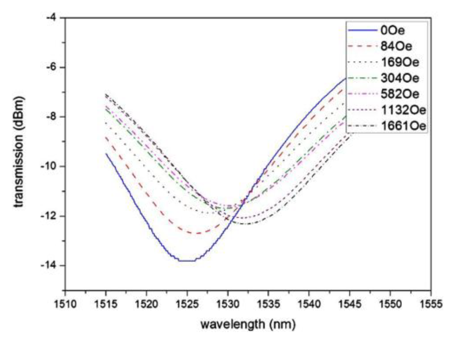
| Wavelength shift | LPG | Fe3O4 | Perpendicular | 0–166.1 mT | 7400 pm/166.1 mT (no linear behavior) | ______ | [29] |
| Resonance wavelength shift | LPG (MOF) | EMG 605 | Perpendicular | 0–166.1 mT | 1946 pm/mT (0–30 mT) | ______ | [42] |
| Resonance wavelength shift | FPI (HC-PCF) | CdFe2O4 | __________ | 5–15 mT | 330 pm/mT | ______ | [49] |
| Resonance wavelength shift | FPI (SMF) | EMG 507 | __________ | 0–40 mT | 431 pm/mT 0.05 mT | ______ | [50] |
| Resonance wavelength shift | FPI (SMF)/FBG | EMG 507 | __________ | 0–60 mT | 400 pm/mT 0.05 mT | ______ | [51] |
| Resonance wavelength shift | FPI (SMF)/FBG | EMG 605 | Parallel | 20–60 mT | 530 pm/mT 0.038 mT | ______ | [52] |
| Wavelength shift | MZI | EMG 605 | Perpendicular | 0–30 mT | 23.67 pm/mT 0.422 mT | ______ | [55] |
| Transmitted power variation | MZI | EMG 605 | Perpendicular | 0–40 mT | −0.3407 dB/mT (10–30 mT) | ______ | [56] |
| Wavelength shift | MZI | EMG 507 | Perpendicular | 0–6.66 mT | 720 pm/mT | ______ | [57] |
| Wavelength shift | MI | Fe3O4 | Perpendicular | 0–200 mT | 64.9 pm/mT | ______ | [61] |
| Wavelength shift Intensity variation | SI | EMG 605 | Perpendicular | 0–30 mT | 167 pm/mT 0.060 mT 3.998 dB/mT (dynamic) | 10–30 ms | [65] |
| Wavelength shift | Loyt-SI | EMG 605 | Perpendicular | 0–20 mT | 5928 pm/mT | ______ | [66] |
| Wavelength shift | SI | EMG 507 | Parallel | 10–40 mT | 1073 pm/mT 0.001 mT | ______ | [67] |
| Wavelength shift | SI | Fe3O4 | Perpendicular | 10–25 mT 41–60 mT | 5300 and −5800 pm/mT 3840 and −4300 pm/mT | ______ | [87] |
| Wavelength shift | SPR/DLUWT | EMG 607 | Parallel | <10 mT (only linear behavior) | ~10,000 pm/mT ~0.3 mT | ______ | [73] |
| Wavelength shift | SPR/MNF | EMG 507 | Perpendicular | 0–34.9 mT | 3030 pm/mT | ______ | [74] |
| Wavelength shift | SPR/D-shaped PCF | Fe3O4 | 0–55 mT | 870 pm/mT | ______ | [75] | |
| Ring down time | FLRDS/etched fiber | EMG 507 | Perpendicular | 0–65 mT | −1.256 mT/μs 2.5 mT | ______ | [78] |
| Wavelength shift Intensity variation | CCMI | Fe3O4 | Perpendicular | 0–21.4 mT 0–185.2 mT | −162.06 pm/mT −0.098 dB/mT | ______ | [79] |
| Wavelength shift | Tapered PCF | EMG 507 | Parallel | 10–60 mT | 160.4 pm/mT 0.062 mT | 30 min | [80] |
| Wavelength shift | U-bent NCF | EMG 605 | Perpendicular | 1.6–9.6 mT | 3185.2 pm/mT | ______ | [81] |
| Wavelength shift Intensity variation | SMS | Fe3O4 | Perpendicular | 3–11 mT | 659 pm/mT 1.185 dB/mT | ______ | [82] |
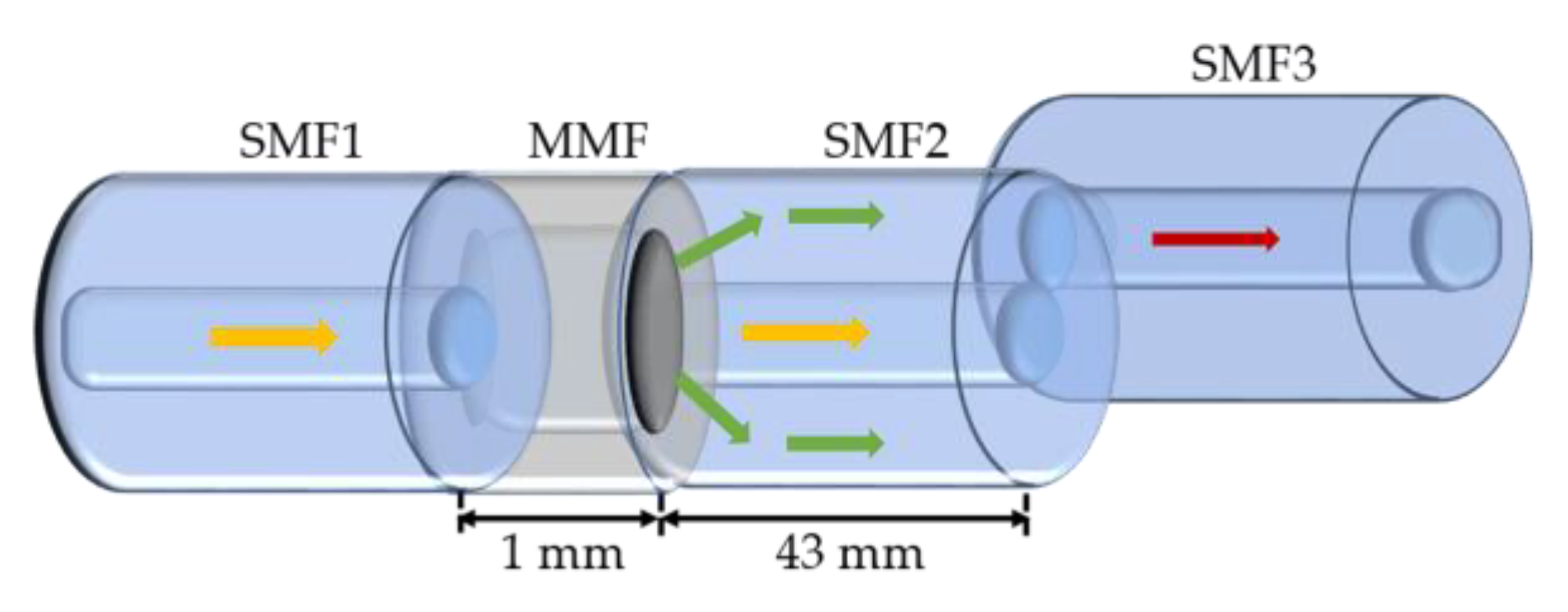
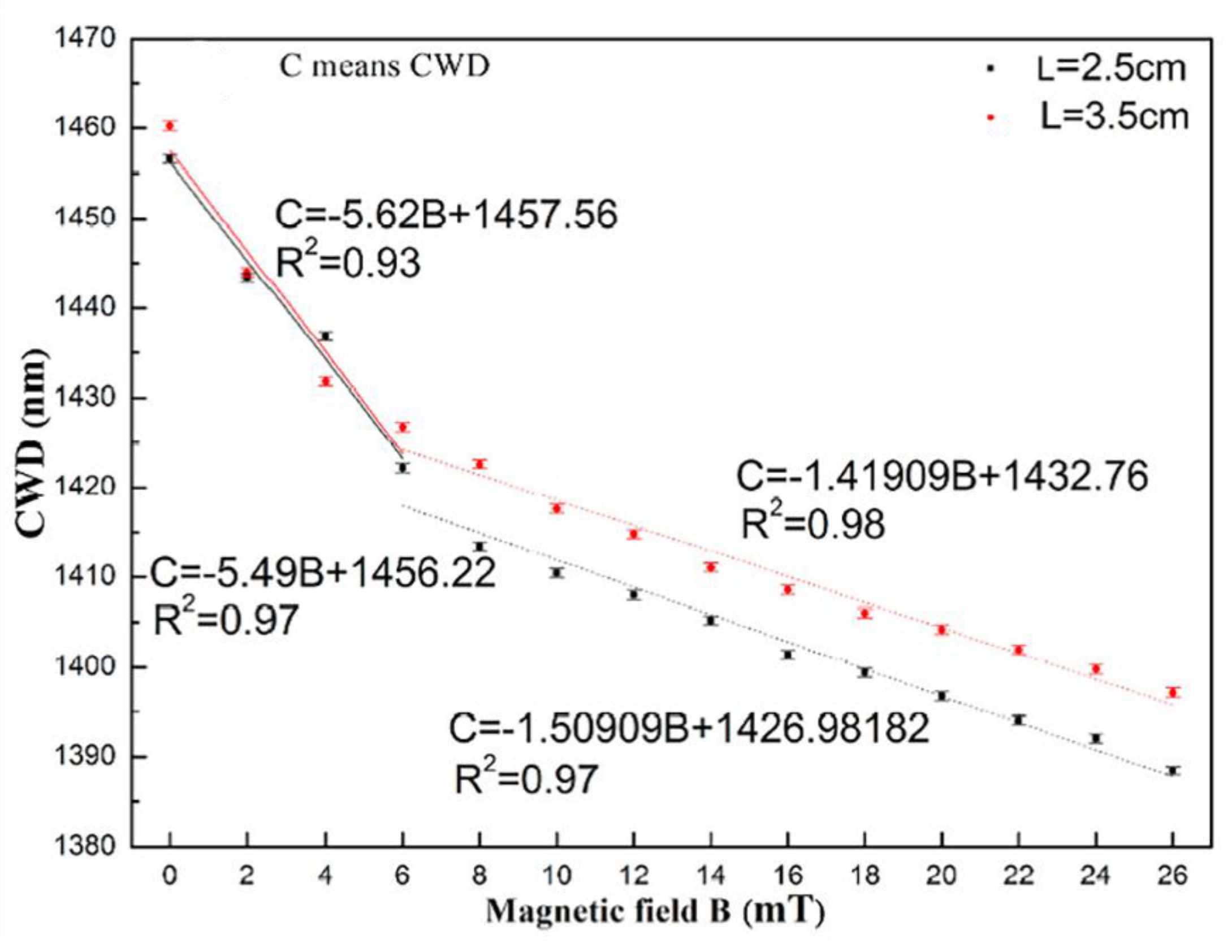
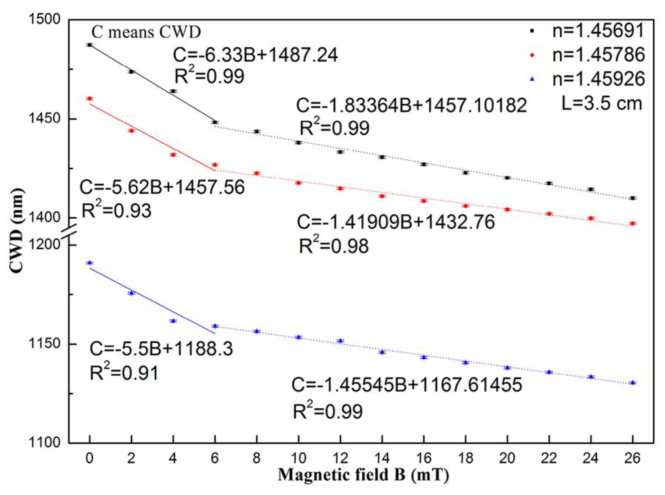
| Coupling wavelength dip | SNS/RIMC | Exp08103 | Perpendicular | ≤6 mT 6–26 mT | 6330 pm/mT 1830 pm/mT | ______ | [83] |
| Wavelength shift | Etched SMS | Fe3O4 | Perpendicular | 12.0–32.5 mT | −168.6 pm/mT | ______ | [84] |
| Wavelength shift Transmission loss | SNS | EMG 605 | __________ | 4–10 mT | 905 pm/mT 0.748 dB/mT | ______ | [85] |
© 2018 by the authors. Licensee MDPI, Basel, Switzerland. This article is an open access article distributed under the terms and conditions of the Creative Commons Attribution (CC BY) license (http://creativecommons.org/licenses/by/4.0/).
Share and Cite
Alberto, N.; Domingues, M.F.; Marques, C.; André, P.; Antunes, P. Optical Fiber Magnetic Field Sensors Based on Magnetic Fluid: A Review. Sensors 2018, 18, 4325. https://doi.org/10.3390/s18124325
Alberto N, Domingues MF, Marques C, André P, Antunes P. Optical Fiber Magnetic Field Sensors Based on Magnetic Fluid: A Review. Sensors. 2018; 18(12):4325. https://doi.org/10.3390/s18124325
Chicago/Turabian StyleAlberto, Nélia, Maria Fátima Domingues, Carlos Marques, Paulo André, and Paulo Antunes. 2018. "Optical Fiber Magnetic Field Sensors Based on Magnetic Fluid: A Review" Sensors 18, no. 12: 4325. https://doi.org/10.3390/s18124325
APA StyleAlberto, N., Domingues, M. F., Marques, C., André, P., & Antunes, P. (2018). Optical Fiber Magnetic Field Sensors Based on Magnetic Fluid: A Review. Sensors, 18(12), 4325. https://doi.org/10.3390/s18124325