Monocular Stereo Measurement Using High-Speed Catadioptric Tracking

Abstract
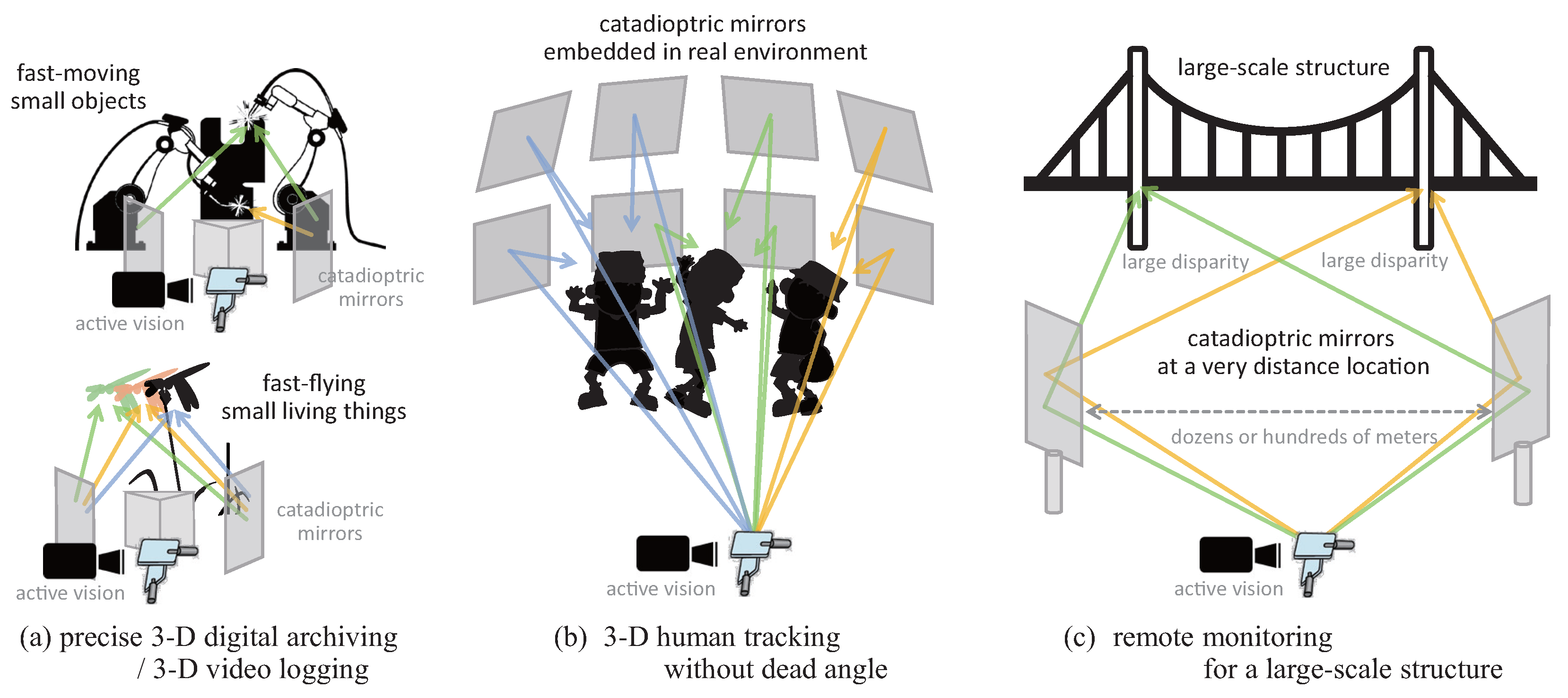
:1. Introduction
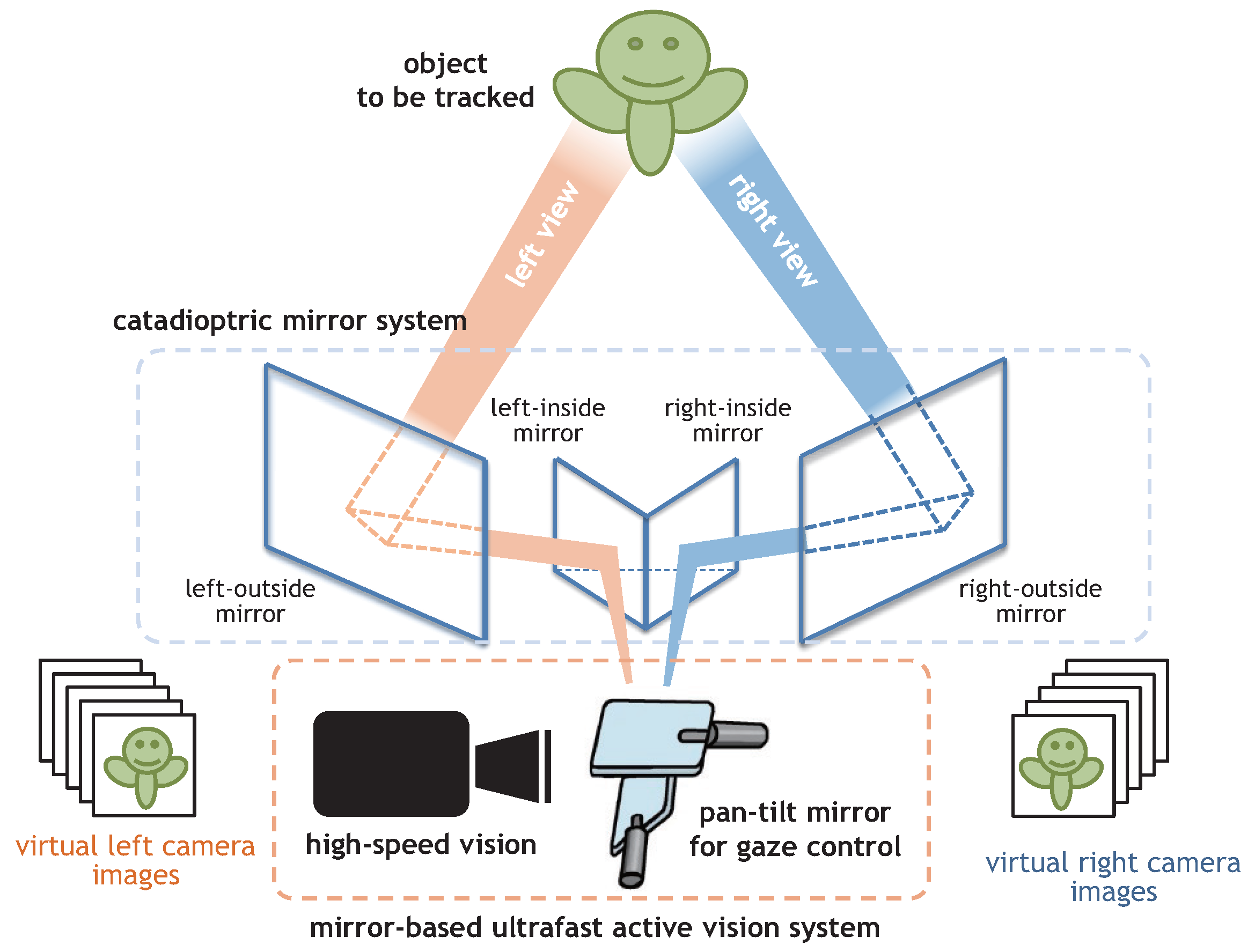
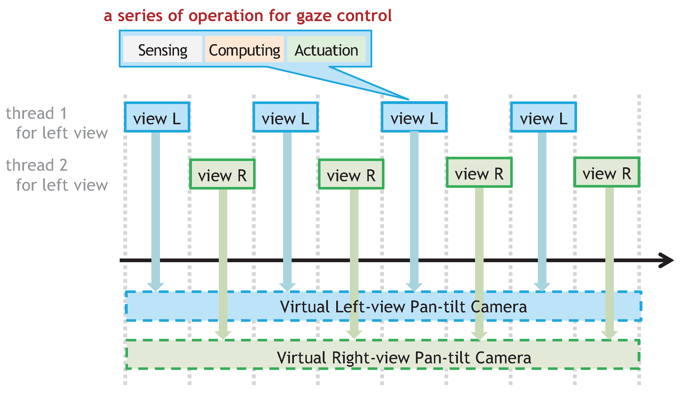
2. Catadioptric Stereo Tracking Using Multithread Gaze Control
3. Geometry of Catadioptric Stereo Tracking
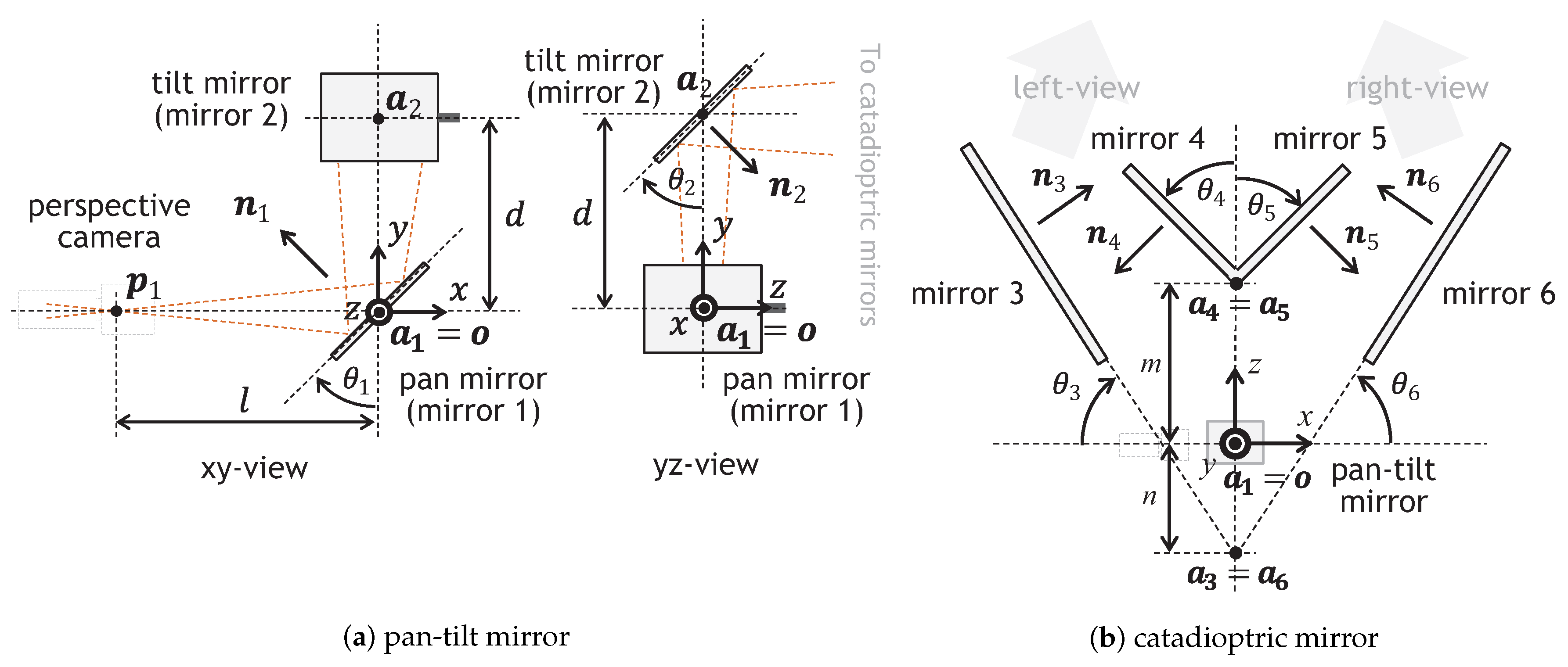
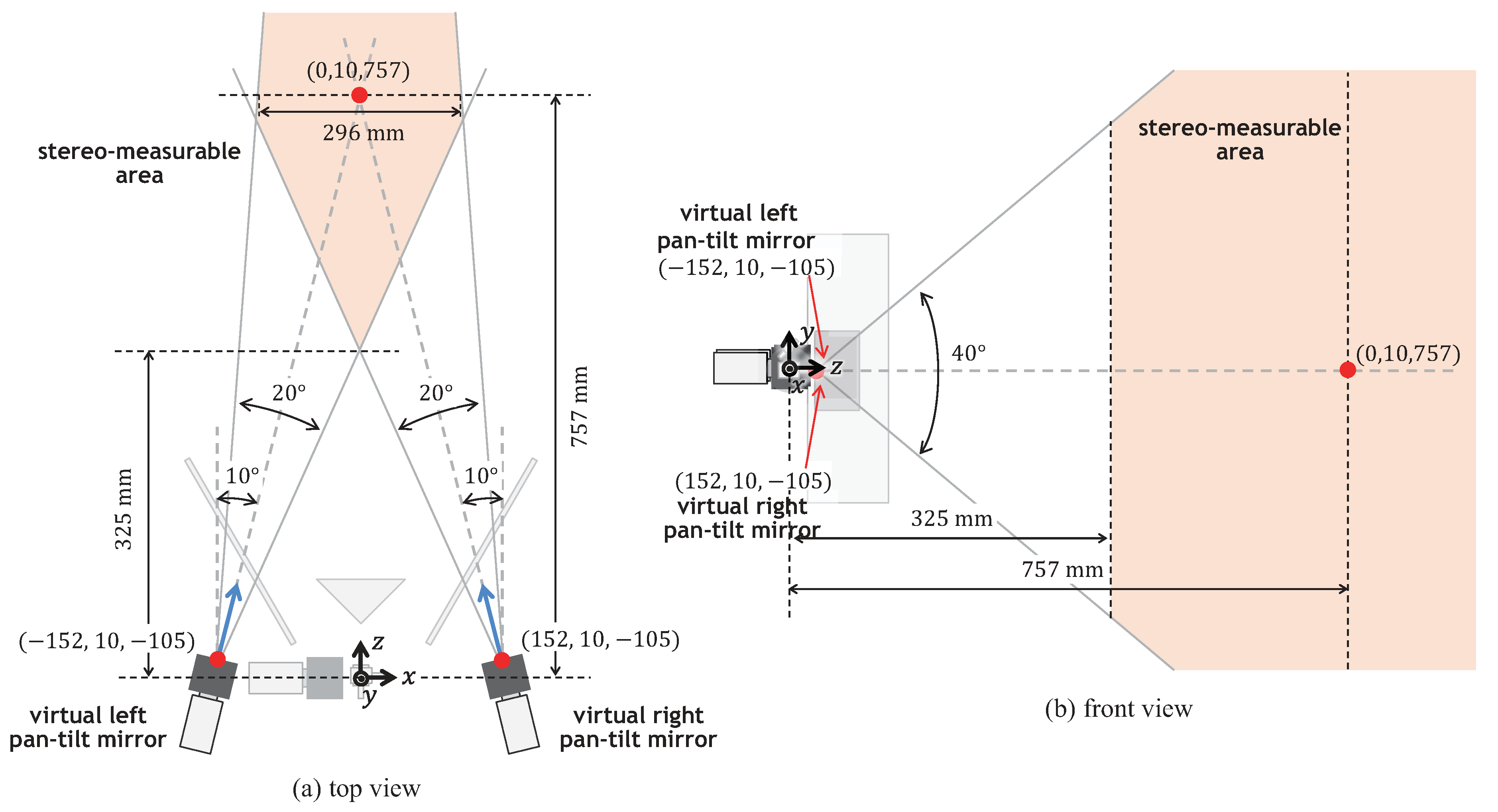
3.1. Geometrical Definitions
3.1.1. Pan-Tilt Mirror System
3.1.2. Catadioptric Mirror System
3.2. Camera Parameters of Virtual Pan-Tilt Cameras
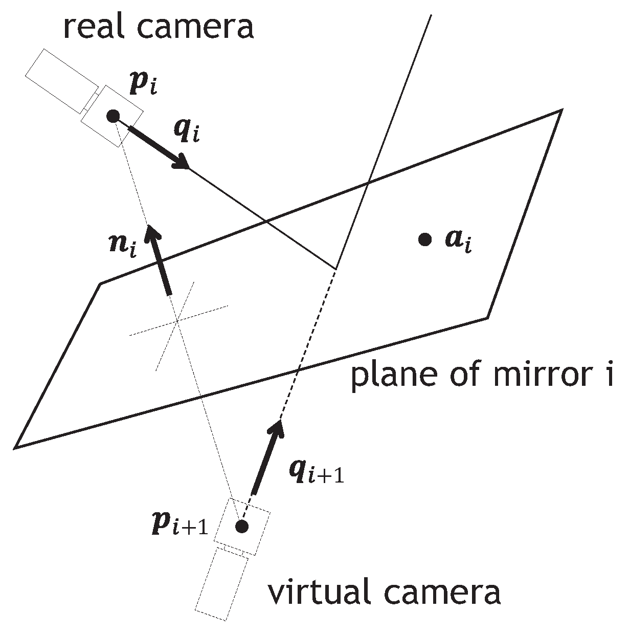
3.2.1. Mirror Reflection
3.2.2. Pan-Tilt Mirror System
3.2.3. Catadioptric Mirror System
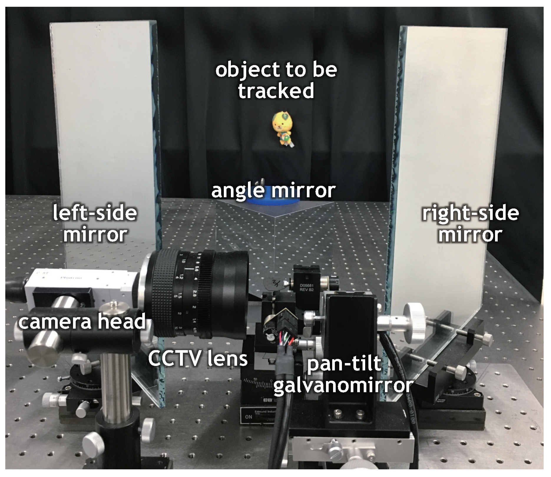
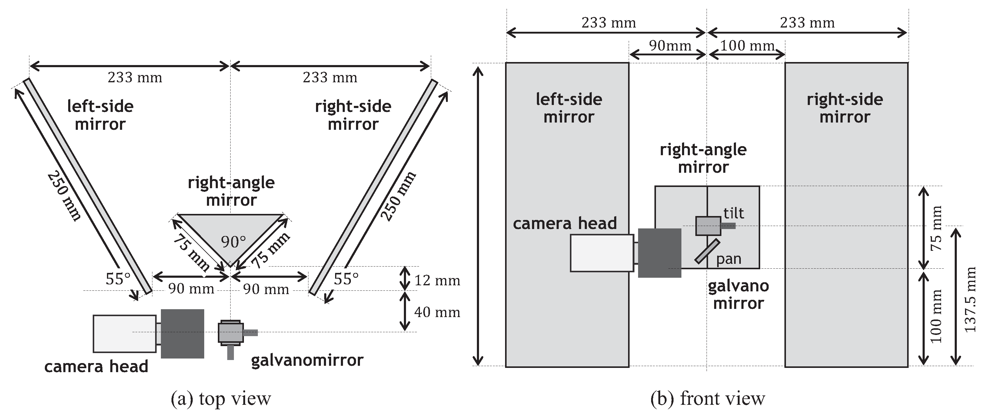
4. Catadioptric Stereo Tracking System
4.1. System Configuration
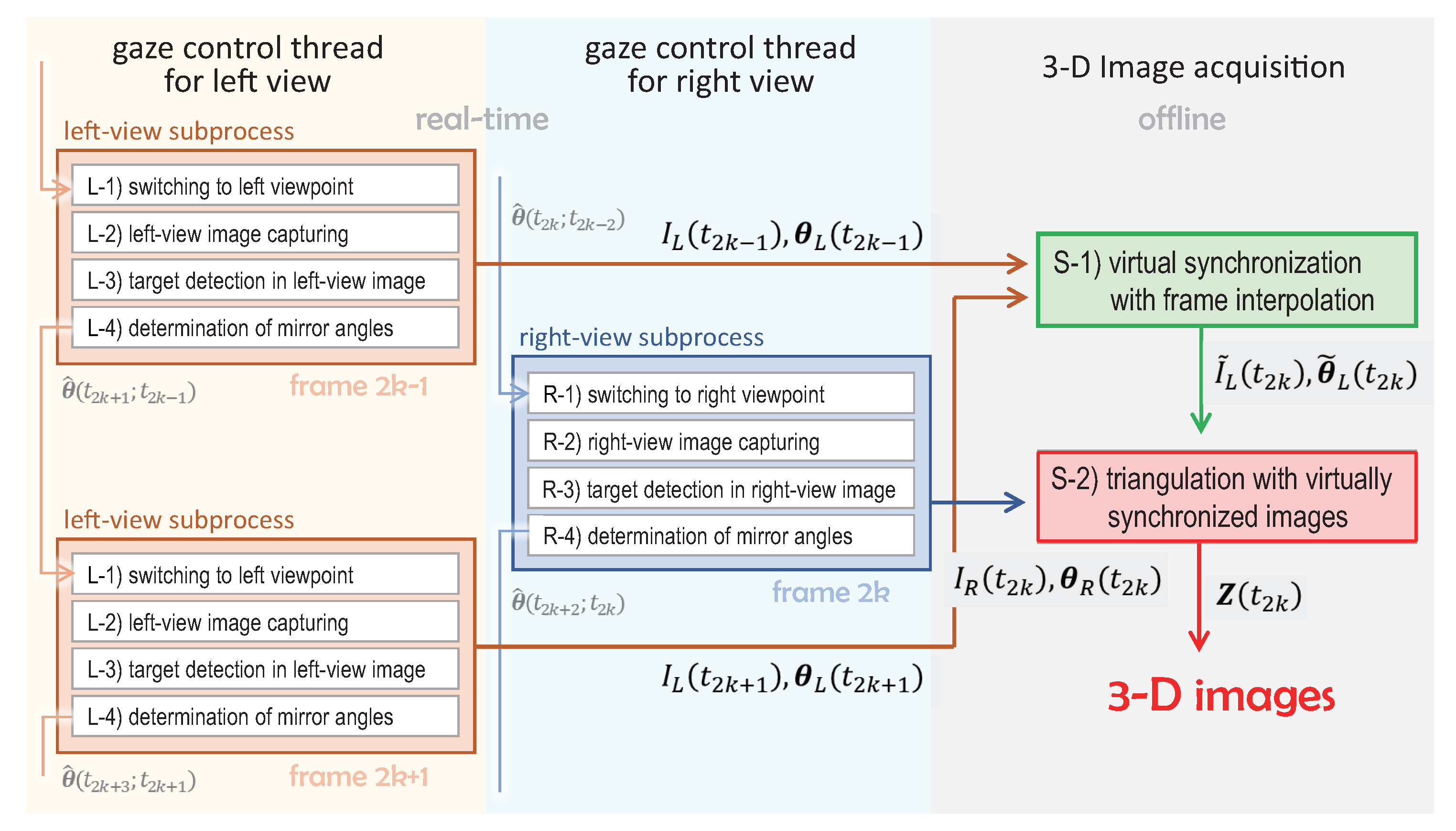
4.2. Implemented Algorithm
4.2.1. Stereo Tracking Process with Multithread Gaze Control
4.2.2. 3D Image Estimation with Virtually Synchronized Images
4.3. Specifications
5. Experiments
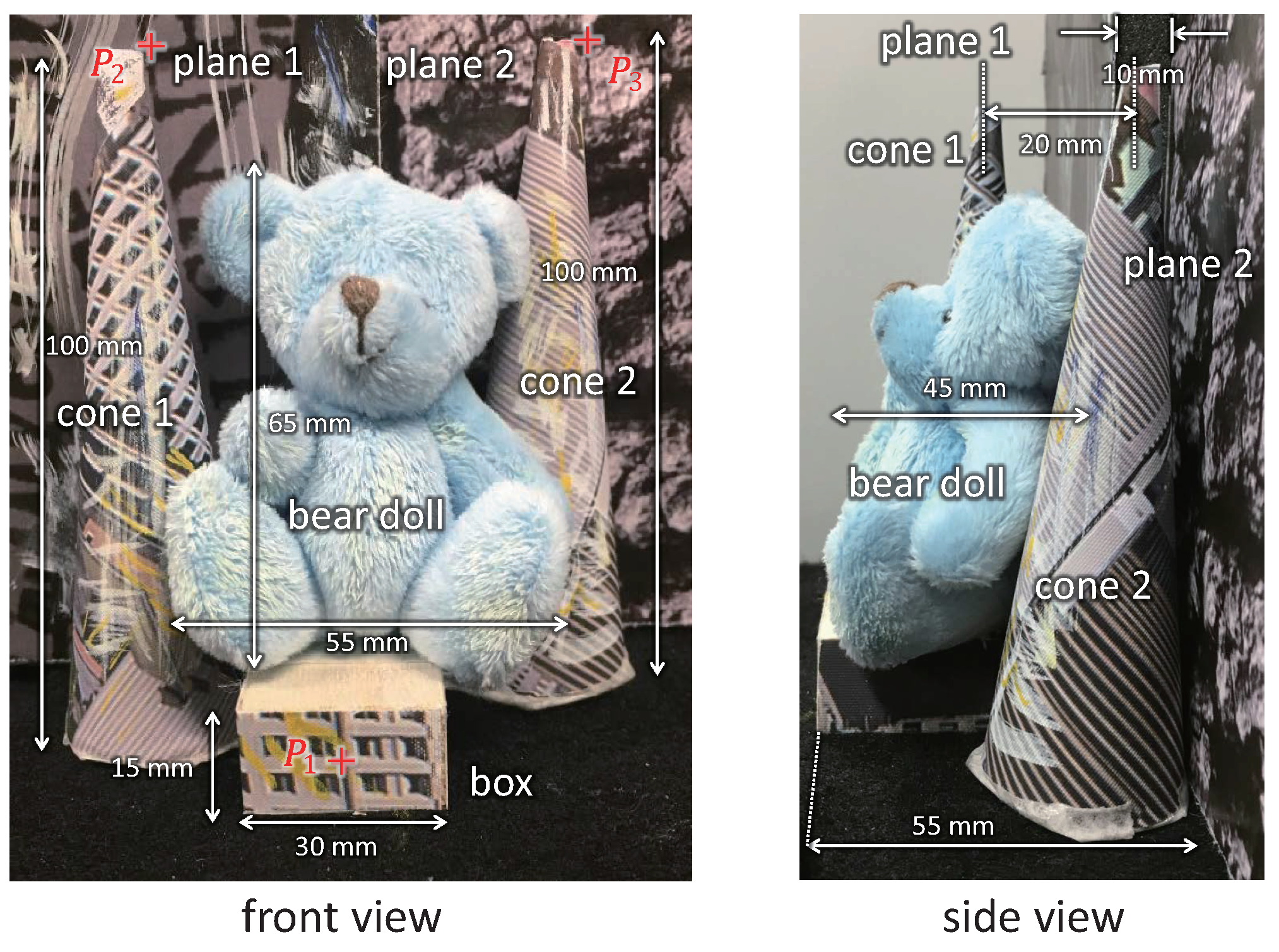
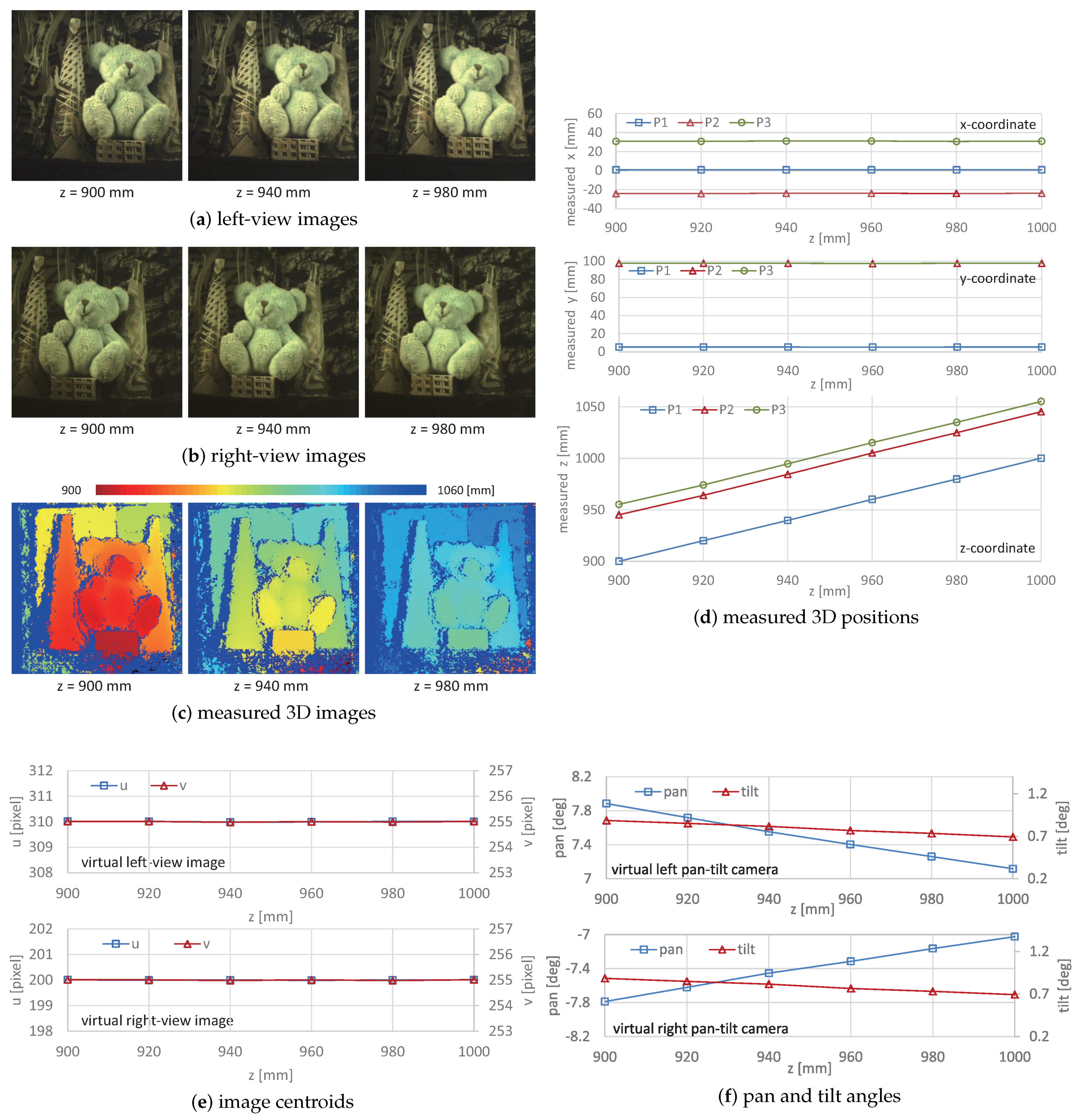
5.1. 3D Shapes of Stationary Objects
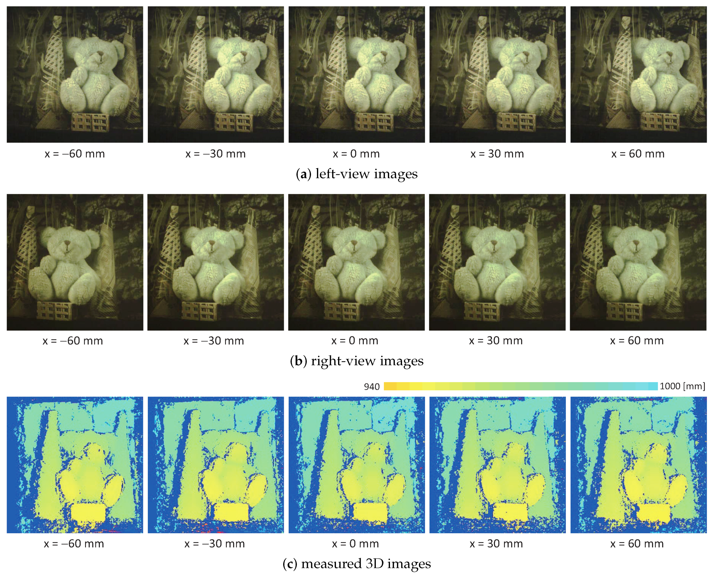
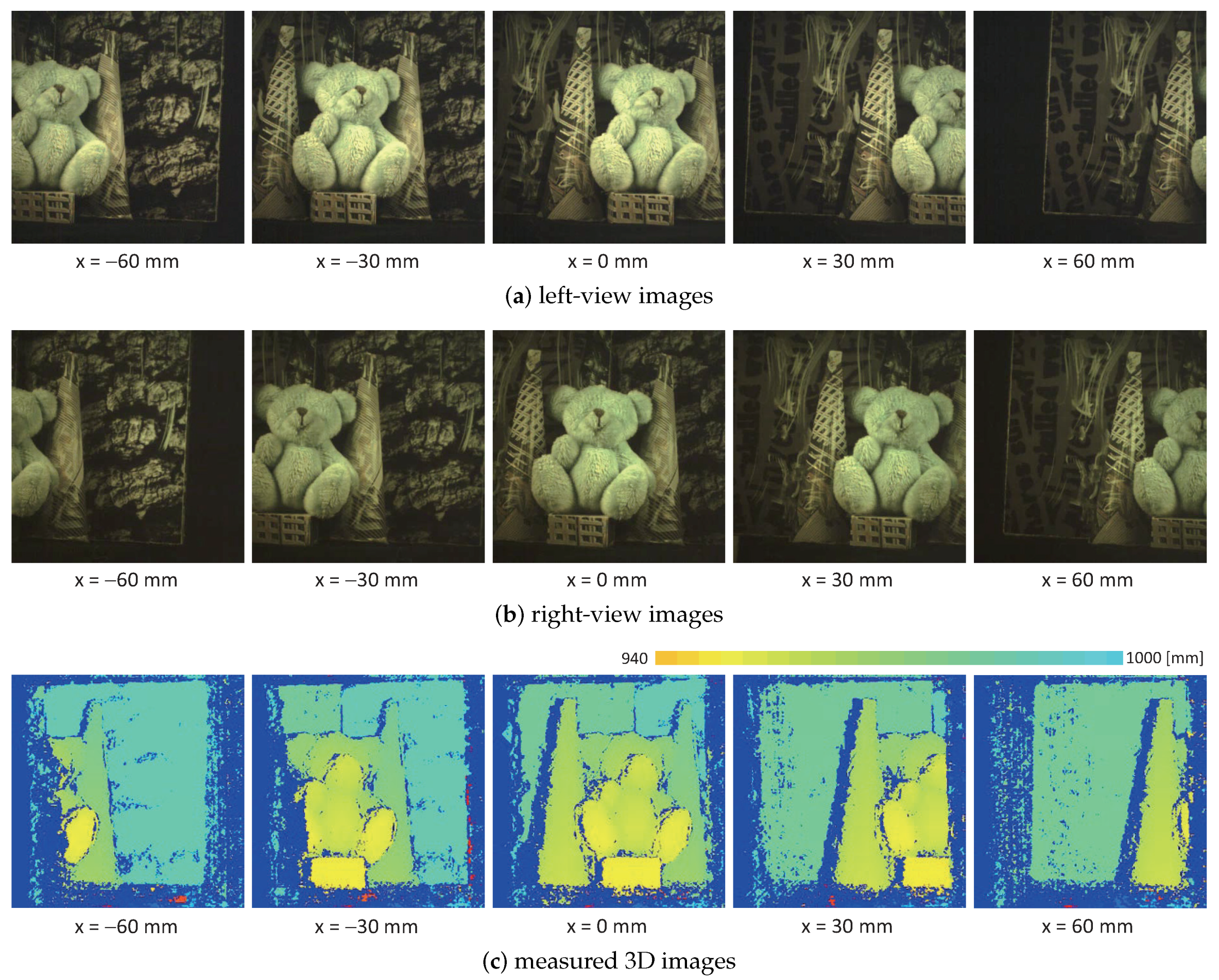
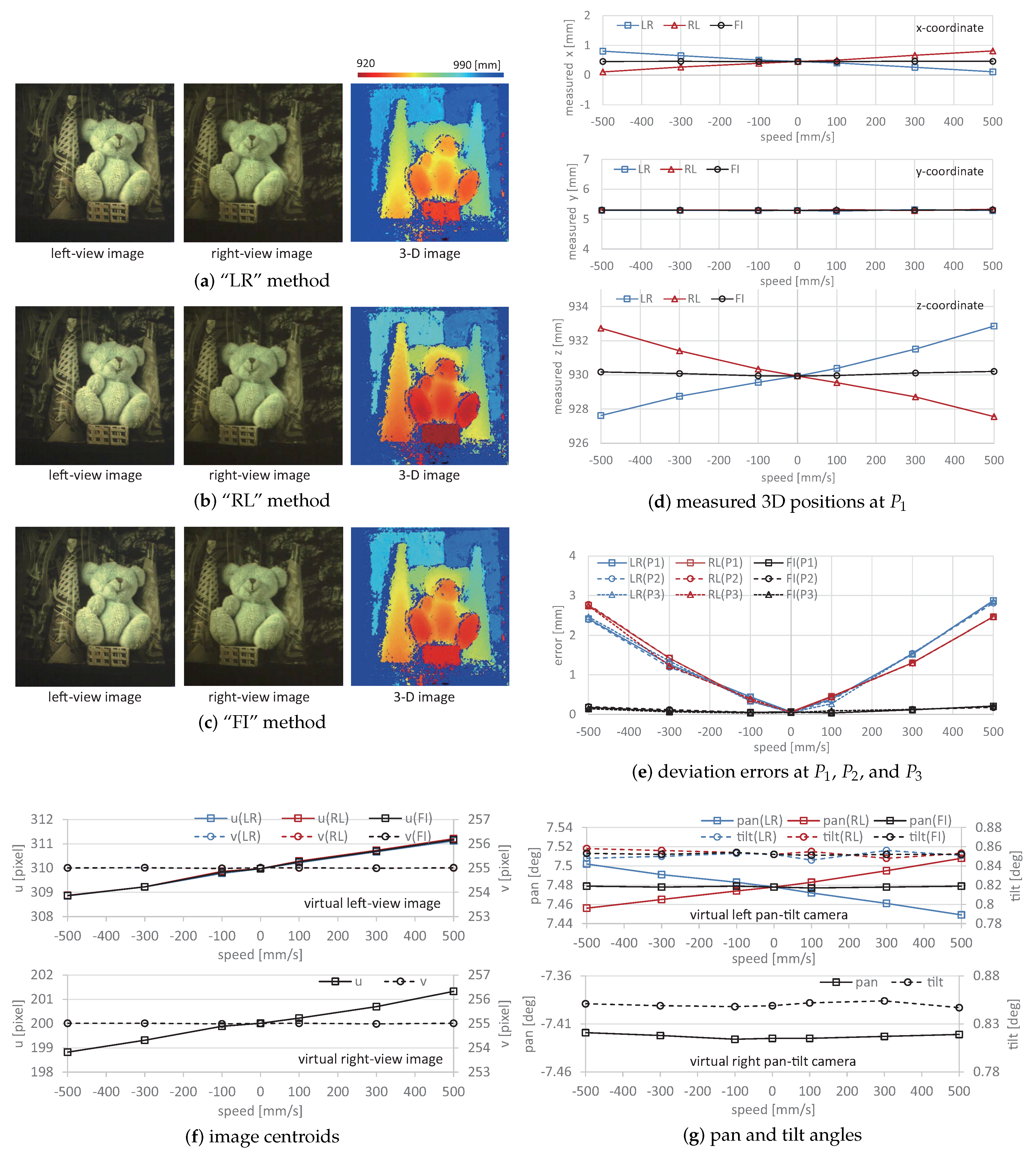
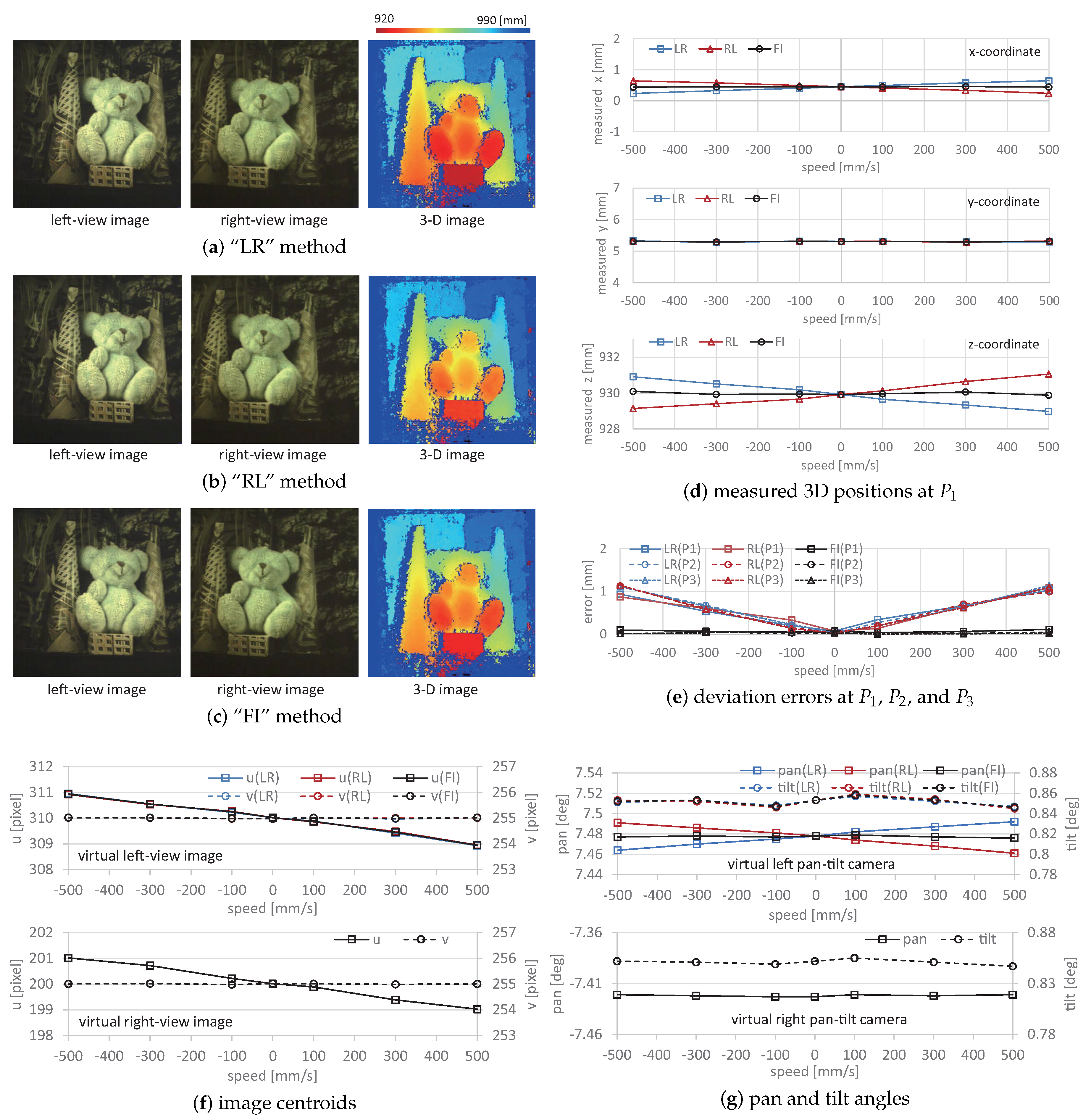
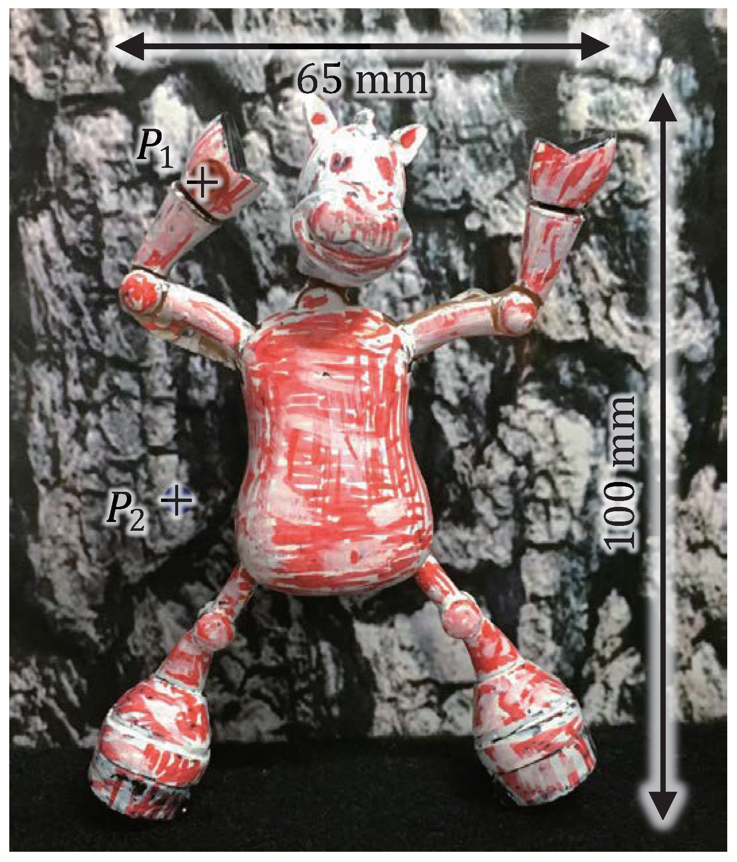
5.2. 3D Shape of Moving Objects
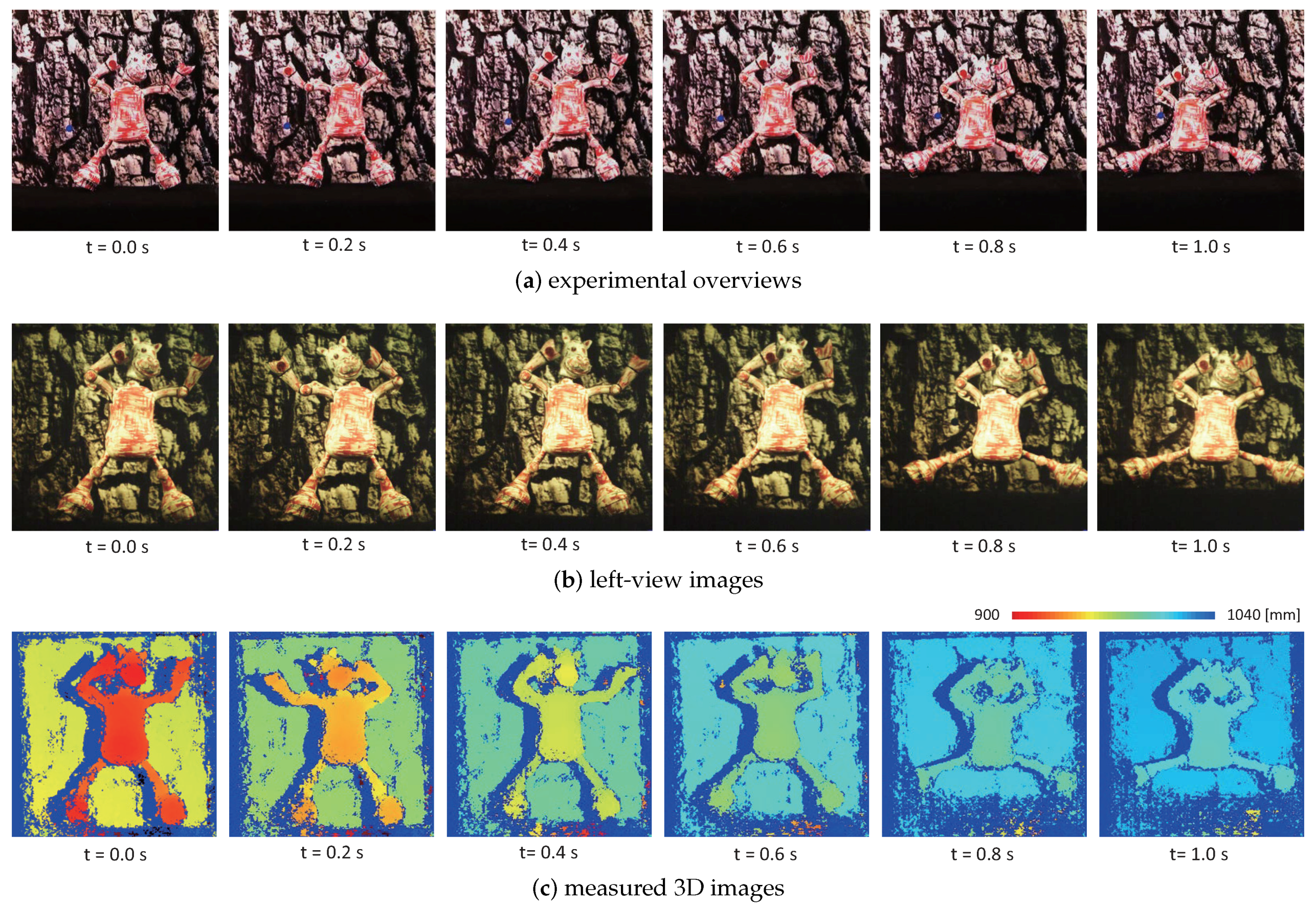
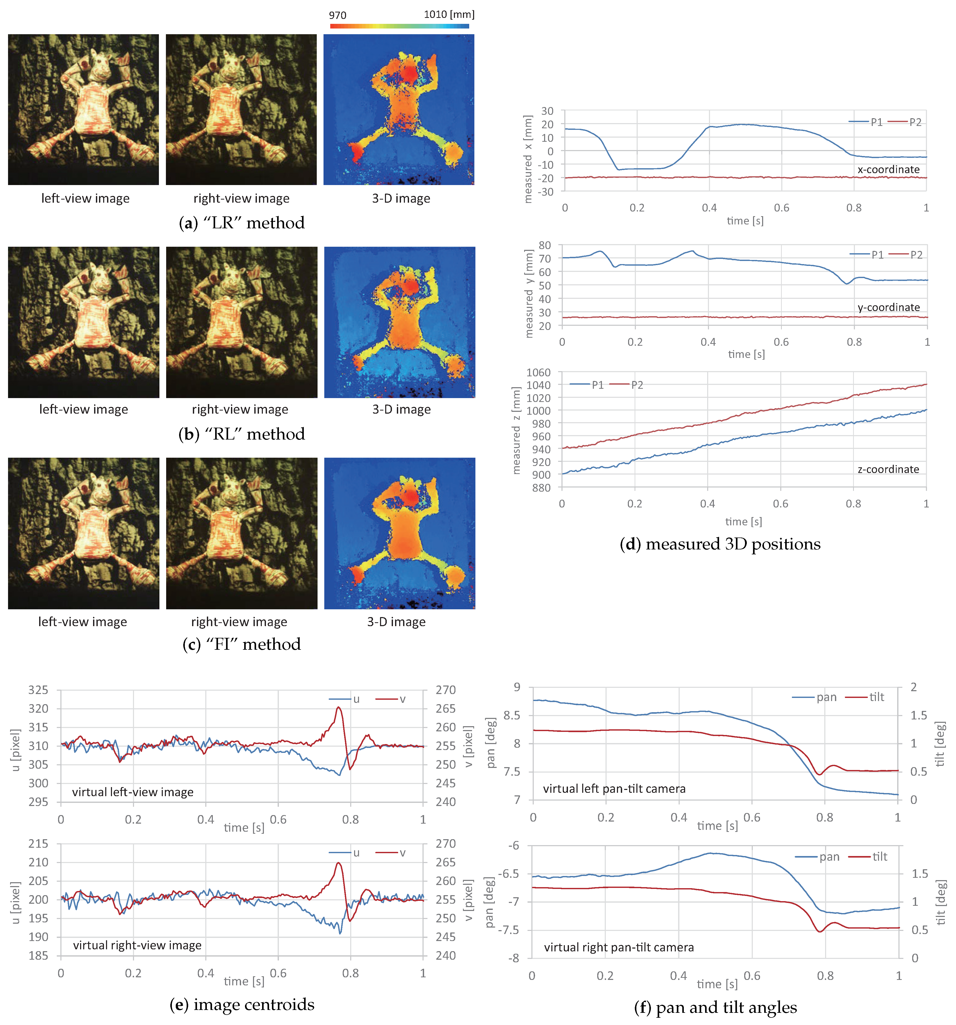
5.3. Dancing Doll in 3D Space
6. Conclusions
Author Contributions
Conflicts of Interest
References
- Scharstein, D.; Szeliski, R. A taxonomy and evaluation of dense two-frame stereo correspondence algorithms. Int. J. Comput. Vis. 2002, 47, 7–42. [Google Scholar] [CrossRef]
- Brown, M.Z.; Burschka, D.; Hager, G.D. Advances in computational stereo. IEEE Trans. Pattern Anal. Mach. Intell. 2003, 25, 993–1008. [Google Scholar] [CrossRef]
- Lazaros, N.; Sirakoulis, G.C.; Gasteratos, A. Review of stereo vision algorithms: From software to hardware. Int. J. Optomechatron. 2008, 2, 435–462. [Google Scholar] [CrossRef]
- Tombari, F.; Mattoccia, S.; Stefano, L.D.; Addimanda, E. Classification and evaluation of cost aggregation methods for stereo correspondence. In Proceedings of the IEEE Conference on Computer Vision and Pattern Recognition, Anchorage, AK, USA, 24–26 June 2008; pp. 1–8. [Google Scholar]
- Herrera, P.J.; Pajares, G.; Guijarro, M.; Ruz, J.J.; Cruz, J.M. A stereovision matching strategy for images captured with fish-eye lenses in forest environments. Sensors 2011, 11, 1756–1783. [Google Scholar] [CrossRef] [PubMed]
- Tippetts, B.; Lee, D.J.; Lillywhite, K.; Archibald, J. Review of stereo vision algorithms and their suitability for resource limited systems. J. Real-Time Image Process. 2013, 11, 5–25. [Google Scholar] [CrossRef]
- Liu, J.; Li, C.; Fan, X.; Wang, Z. Reliable fusion of stereo matching and depth sensor for high quality dense depth maps. Sensors 2015, 15, 20894–20924. [Google Scholar] [CrossRef] [PubMed]
- Hamzah, R.A.; Ibrahim, H. Literature survey on stereo vision disparity map algorithms. J. Sensors 2016, 2016, 8742920. [Google Scholar] [CrossRef]
- Wang, L.; Yang, R.; Gong, M.; Liao, M. Real-time stereo using approximated joint bilateral filtering and dynamic programming. J. Real-Time Image Process. 2014, 9, 447–461. [Google Scholar] [CrossRef]
- Sun, J.; Zheng, N.N.; Shum, H.Y. Stereo matching using belief propagation. IEEE Trans. Pattern Anal. Mach. Intell. 2003, 25, 787–800. [Google Scholar]
- Yang, Q.; Wang, L.; Yang, R.; Wang, S.; Liao, M.; Nister, D. Real-time global stereo matching using hierarchical belief propagation. In Proceedings of the British Machine Vision Conference, Edinburgh, UK, 4–7 September 2006; pp. 989–998. [Google Scholar]
- Liang, C.K.; Cheng, C.C.; Lai, Y.C.; Chen, L.G.; Chen, H.H. Hardware-efficient belief propagation. IEEE Trans. Circuits Syst. Video Technol. 2011, 21, 525–537. [Google Scholar] [CrossRef]
- Boykov, Y.; Veksler, O.; Zabih, R. Fast approximate energy minimization via graph cuts. IEEE Trans. Pattern Anal. Mach. Intell. 2001, 23, 1222–1239. [Google Scholar] [CrossRef]
- Woodford, O.; Torr, P.; Reid, I.; Fitzgibbon, A. Global stereo reconstruction under second-order smoothness priors. IEEE Trans. Pattern Anal. Mach. Intell. 2009, 31, 2115–2128. [Google Scholar] [CrossRef] [PubMed]
- Yoon, K.J.; Kweon, I.S. Adaptive support-weight approach for correspondence search. IEEE Trans. Pattern Anal. Mach. Intell. 2006, 28, 650–656. [Google Scholar] [CrossRef] [PubMed]
- Hosni, A.; Bleyer, M.; Gelautz, M. Secrets of adaptive support weight techniques for local stereo matching. Comput. Vis. Image Underst. 2013, 117, 620–632. [Google Scholar] [CrossRef]
- Chen, D.; Ardabilian, M.; Chen, L. A fast trilateral filter-based adaptive support weight method for stereo matching. IEEE Trans. Circuits Syst. Video Technol. 2015, 25, 730–743. [Google Scholar] [CrossRef]
- Veksler, O. Fast variable window for stereo correspondence using integral images. In Proceedings of the IEEE Conference on Computer Vision and Pattern Recognition, Madison, WI, USA, 16–22 June 2003; pp. 556–561. [Google Scholar]
- Xu, Y.; Zhao, Y.; Ji, M. Local stereo matching with adaptive shape support window based cost aggregation. Appl. Opt. 2014, 53, 6885–6892. [Google Scholar] [CrossRef] [PubMed]
- McCullagh, B. Real-time disparity map computation using the cell broadband engine. J. Real-Time Image Process. 2012, 7, 87–93. [Google Scholar] [CrossRef]
- Sinha, S.N.; Scharstein, D.; Szeliski, R. Efficient high-resolution stereo matching using local plane sweeps. In Proceedings of the IEEE Conference on Computer Vision and Pattern Recognition, Columbus, OH, USA, 24–27 June 2014; pp. 1582–1589. [Google Scholar]
- Yang, R.; Pollefeys, M. Multi-resolution real-time stereo on commodity graphics hardware. In Proceedings of the IEEE Conference on Computer Vision and Pattern Recognition, Madison, WI, USA, 16–22 June 2003; pp. 211–217. [Google Scholar]
- Gong, M.; Yang, Y.H. Near Real-time reliable stereo matching using programmable graphics hardware. In Proceedings of the IEEE Conference on Computer Vision and Pattern Recognition, San Diego, CA, USA, 20–26 June 2005; pp. 924–931. [Google Scholar]
- Grauer-Gray, S.; Kambhamettu, C. Hierarchical belief propagation to reduce search space Using CUDA for stereo and motion estimation. In Proceedings of the Workshop on Applications of Computer Vision, Snowbird, UT, USA, 7–8 December 2009; pp. 1–8. [Google Scholar]
- Humenberger, M.; Zinner, C.; Weber, M.; Kubinger, W.; Vincze, M. A fast stereo matching algorithm suitable for embedded real-time systems. Comput. Vis. Image Underst. 2010, 114, 1180–1202. [Google Scholar] [CrossRef]
- Mei, X.; Sun, X.; Zhou, M.; Jiao, S.; Wang, H.; Zhang, X. On building an accurate stereo matching system on graphics hardware. In Proceedings of the IEEE International Conference on Computer Vision Workshops, Barcelona, Spain, 6–13 November 2011; pp. 467–474. [Google Scholar]
- Perri, S.; Colonna, D.; Zicari, P.; Corsonello, P. SAD-based stereo matching circuit for FPGAs. In Proceedings of the International Conference on Electronics, Circuits and Systems, Nice, France, 10–13 December 2006; pp. 846–849. [Google Scholar]
- Gardel, A.; Montejo, P.; García, J.; Bravo, I.; Lázaro, J.L. Parametric dense stereovision implementation on a system-on chip (SoC). Sensors 2012, 12, 1863–1884. [Google Scholar] [CrossRef] [PubMed]
- Zhang, X.; Chen, Z. SAD-Based Stereo Vision Machine on a System-on-Programmable-Chip (SoPC). Sensors 2013, 13, 3014–3027. [Google Scholar] [CrossRef] [PubMed]
- Perez-Patricio, M.; Aguilar-Gonzalez, A. FPGA implementation of an efficient similarity-based adaptive window algorithm for real-time stereo matching. J. Real Time-Image Process. 2015, 10, 1–17. [Google Scholar] [CrossRef]
- Krotkov, E.P. Active Computer Vision by Cooperative Focus and Stereo; Springer: New York, NY, USA, 1989; pp. 1–17. ISBN 13:978-1-4613-9665-9. [Google Scholar]
- Wan, D.; Zhou, J. Stereo vision using two PTZ cameras. Comput. Vis. Image Underst. 2008, 112, 184–194. [Google Scholar] [CrossRef]
- Kumar, S.; Micheloni, C.; Piciarelli, C. Stereo localization using dual PTZ cameras. In Proceedings of the International Conference on Computer Analysis of Images and Patterns, Münster, Germany, 2–4 September 2009; pp. 1061–1069. [Google Scholar]
- Kong, W.; Zhang, D.; Wang, X.; Xian, Z.; Zhang, J. Autonomous landing of an UAV with a ground-based actuated infrared stereo vision system. In Proceedings of the IEEE/RSJ International Conference on Intelligent Robots and Systems, Tokyo, Japan, 3–7 November 2013; pp. 2963–2970. [Google Scholar]
- Ahuja, N.; Abbott, A.L. Active stereo: Integrating disparity, vergence, focus, aperture and calibration for surface estimation. IEEE Trans. Pattern Anal. Mach. Intell. 1993, 15, 1007–1029. [Google Scholar] [CrossRef]
- Kim, D.H.; Kim, D.Y.; Hong, H.S.; Chung, M.J. An image-based control scheme for an active stereo vision system. In Proceedings of the IEEE/RSJ International Conference on Intelligent Robots and Systems, Sendai, Japan, 28 September–2 October 2004; pp. 3375–3380. [Google Scholar]
- Barreto, J.P.; Perdigoto, L.; Caseiro, R.; Araujo, H. Active stereo tracking of N<=3 targets using line scan cameras. IEEE Trans. Robot. 2010, 26, 442–457. [Google Scholar]
- Kwon, H.; Yoon, Y.; Park, J.B.; Kak, A.C. Person tracking with a mobile robot using two uncalibrated independently moving cameras. In Proceedings of the IEEE International Conference on Robotics and Automation, Barcelona, Spain, 18–22 April 2005; pp. 2877–2883. [Google Scholar]
- Junejo, I.N.; Foroosh, H. Optimizing PTZ camera calibration from two images. Mach. Vis. Appl. 2012, 23, 375–389. [Google Scholar] [CrossRef]
- Kumar, S.; Micheloni, C.; Piciarelli, C.; Foresti, G.L. Stereo rectification of uncalibrated and heterogeneous images. Pattern Recognit. Lett. 2010, 31, 1445–1452. [Google Scholar] [CrossRef]
- Ying, X.; Peng, K.; Hou, Y.; Guan, S.; Kong, J.; Zha, H. Self-calibration of catadioptric camera with two planar mirrors from silhouettes. IEEE Trans. Pattern Anal. Mach. Intell. 2013, 35, 1206–1220. [Google Scholar] [CrossRef] [PubMed]
- Wu, Z.; Radke, R.J. Keeping a pan-tilt-zoom camera calibrated. IEEE Trans. Circuits Syst. Video Technol. 2013, 35, 1994–2007. [Google Scholar] [CrossRef] [PubMed]
- Schmidt, A.; Sun, L.; Aragon-Camarasa, G.; Siebert, J.P. The calibration of the pan-tilt units for the active stereo head. In Image Processing and Communications Challenges 7; Springer: Cham, Switzerland, 2016; pp. 213–221. [Google Scholar]
- Wan, D.; Zhou, J. Self-calibration of spherical rectification for a PTZ-stereo system. Image Vis. Comput. 2010, 28, 367–375. [Google Scholar] [CrossRef]
- Micheloni, C.; Rinner, B.; Foresti, G.L. Video analysis in pan-tilt-zoom camera networks. IEEE Signal Process. Mag. 2010, 27, 78–90. [Google Scholar] [CrossRef]
- Zhang, Z. A flexible new technique for camera calibration. IEEE Trans. Pattern Anal. Mach. Intell. 2000, 22, 1330–1334. [Google Scholar] [CrossRef]
- Weng, J.; Huang, T.S.; Ahuja, N. Motion and structure from two perspective views: Algorithms, error analysis, and error estimation. IEEE Trans. Pattern Anal. Mach. Intell. 1989, 11, 451–476. [Google Scholar] [CrossRef]
- Sandini, G.; Tistarelli, M. Active tracking strategy for monocular depth inference over multiple frames. IEEE Trans. Pattern Anal. Mach. Intell. 1990, 12, 13–27. [Google Scholar] [CrossRef]
- Davision, A.J. Real-time simultaneous localisation and mapping with a single camera. In Proceedings of the IEEE Conference on Computer Vision and Pattern Recognition, Madison, WI, USA, 16–22 June 2003; pp. 1403–1410. [Google Scholar]
- Adelson, E.H.; Wang, J.Y.A. Single lens stereo with a plenoptic camera. IEEE Trans. Pattern Anal. Mach. Intell. 1992, 14, 99–106. [Google Scholar] [CrossRef]
- Fenimore, E.E.; Cannon, T.M. Coded aperture imaging with uniformly redundant arrays. Appl. Opt. 1978, 17, 337–347. [Google Scholar] [CrossRef] [PubMed]
- Hiura, S.; Matsuyama, T. Depth measurement by the multifocus camera. In Proceedings of the IEEE Conference on Computer Vision and Pattern Recognition, Santa Barbara, CA, USA, 23–25 June 1998; pp. 953–959. [Google Scholar]
- Mitsumoto, H.; Tamura, S.; Okazaki, K.; Kajimi, N.; Fukui, Y. 3D reconstruction using mirror images based on a plane symmetry recovery method. IEEE Trans. Pattern Anal. Mach. Intell. 1992, 14, 941–945. [Google Scholar] [CrossRef]
- Zhang, Z.; Tsui, H. 3D reconstruction from a single view of an object and its image in a plane mirror. In Proceedings of the International Conference on Pattern Recognition, Brisbane, Australia, 16–20 August 1998; pp. 1174–1176. [Google Scholar]
- Goshtasby, A.; Gruver, W. Design of a single lens stereo camera system. Pattern Recognit. 1993, 26, 923–937. [Google Scholar] [CrossRef]
- Gluckman, J.; Nayar, S.K. Catadioptric stereo using planar mirrors. Int. J. Comput. Vis. 2001, 44, 65–79. [Google Scholar] [CrossRef]
- Pachidis, T.P.; Lygouras, J.N. Pseudostereo-vision system: A monocular stereo-vision system as a sensor for real-time robot applications. IEEE Trans. Instrum. Meas. 2007, 56, 2547–2560. [Google Scholar] [CrossRef]
- Inaba, M.; Hara, T.; Inoue, H. A stereo viewer based on a single camera with view-control mechanism. In Proceedings of the IEEE/RSJ International Conference on Intelligent Robots and Systems, Yokohama, Japan, 26–30 July 1993; pp. 1857–1865. [Google Scholar]
- Yu, L.; Pan, B. Structure parameter analysis and uncertainty evaluation for single-camera stereo-digital image correlation with a four-mirror adapter. Appl. Opt. 2016, 55, 6936–6946. [Google Scholar] [CrossRef] [PubMed]
- Lee, D.H.; Kweon, I.S. A novel stereo camera system by a biprism. IEEE Trans. Rob. Autom. 2001, 16, 528–541. [Google Scholar]
- Xiao, Y.; Lim, K.B. A prism-based single-lens stereovision system: From trinocular to multi-ocular. Image Vis. Comput. 2007, 25, 1725–1736. [Google Scholar] [CrossRef]
- Southwell, D.; Basu, A.; Fiala, M.; Reyda, J. Panoramic stereo. In Proceedings of the IEEE International Conference on Pattern Recognition, Vienna, Austria, 25–19 August 1996; pp. 378–382. [Google Scholar]
- Peleg, S.; Ben-Ezra, M. Stereo panorama with a single camera. In Proceedings of the IEEE Conference on Computer Vision and Pattern Recognition, Collins, CO, USA, 23–25 June 1999; pp. 395–401. [Google Scholar]
- Yi, S.; Ahuja, N. An omnidirectional stereo vision system using a single camera. In Proceedings of the IEEE International Conference on Pattern Recognition, Hong Kong, China, 20–24 August 2006; pp. 861–865. [Google Scholar]
- Li, W.; Li, Y.F. Single-camera panoramic stereo imaging system with a fisheye lens and a convex mirror. Opt. Exp. 2011, 19, 5855–5867. [Google Scholar] [CrossRef] [PubMed]
- Xiang, Z.; Sun, B.; Dai, X. The camera itself as a calibration pattern: A novel self-calibration method for non-central catadioptric cameras. Sensors 2012, 12, 7299–7317. [Google Scholar] [CrossRef] [PubMed]
- Jaramillo, C.; Valenti, R.G.; Guo, L.; Xiao, J. Design and analysis of a single-camera omnistereo sensor for quadrotor micro aerial vehicles (MAVs). Sensors 2016, 16, 217. [Google Scholar] [CrossRef] [PubMed]
- Gluckman, J.; Nayar, S.K. Rectified catadioptric stereo sensors. IEEE Trans. Pattern Anal. Mach. Intell. 2002, 24, 224–236. [Google Scholar] [CrossRef]
- Shimizu, M.; Okutomi, M. Calibration and rectification for reflection stereo. In Proceedings of the IEEE Conference on Computer Vision and Pattern Recognition, Anchorage, AK, USA, 24–26 June 2008; pp. 1–8. [Google Scholar]
- Zhu, L.; Weng, W. Catadioptric stereo-vision system for the real-time monitoring of 3D behavior in aquatic animals. Physiol. Behav. 2007, 91, 106–119. [Google Scholar] [CrossRef] [PubMed]
- Gluckman, J.; Nayar, S.K.; Thoresz, K.J. Real-Time omnidirectional and panoramic stereo. Comput. Vis. Image Underst. 1998, 1, 299–303. [Google Scholar]
- Koyasu, H.; Miura, J.; Shirai, Y. Real-time omnidirectional stereo for obstacle detection and tracking in dynamic environments. In Proceedings of the IEEE/RSJ International Conference on Intelligent Robots and Systems, Maui, HI, USA, 29 October–3 November 2001; pp. 31–36. [Google Scholar]
- Voigtlnder, A.; Lange, S.; Lauer, M.; Riedmiller, M.A. Real-time 3D ball recognition using perspective and catadioptric cameras. In Proceedings of the European Conference on Mobile Robotics, Freiburg, Germany, 19–21 September 2007. [Google Scholar]
- Lauer, M.; Schönbein, M.; Lange, S.; Welker, S. 3D-object tracking with a mixed omnidirectional stereo camera system. Mechatronics 2011, 21, 390–398. [Google Scholar] [CrossRef]
- Hmida, R.; Ben Abdelali, A.; Comby, F.; Lapierre, L.; Mtibaa, A.; Zapata, R. Hardware implementation and validation of 3D underwater shape reconstruction algorithm using a stereo-catadioptric system. Appl. Sci. 2016, 6, 247. [Google Scholar] [CrossRef]
- Liang, C.K.; Lin, T.H.; Wong, B.Y.; Liu, C.; Chen, H.H. Programmable aperture photography: Multiplexed light field acquisition. ACM Trans. Graph. 2008, 27. [Google Scholar] [CrossRef]
- Moriue, Y.; Takaki, T.; Yamamoto, K.; Ishii, I. Monocular stereo image processing using the viewpoint switching iris. In Proceedings of the IEEE International Conference on Robotics and Automation, Kobe, Japan, 12–17 May 2009; pp. 2804–2809. [Google Scholar]
- Ishii, I.; Tatebe, T.; Gu, Q.; Moriue, Y.; Takaki, T.; Tajima, K. 2000 fps real-time vision system with high-frame-rate video recording. In Proceedings of the IEEE International Conference on Robotics and Automation, Anchorage, AK, USA, 3–7 May 2010; pp. 1536–1541. [Google Scholar]
- Chen, S.E.; Williams, L. View interpolation for image synthesis. IEEE Trans. Pattern Anal. Mach. Intell. 1998, 20, 218–226. [Google Scholar]
- McMillan, L.; Bishop, G. Plenoptic Modeling: An image-based rendering system. In Proceedings of the ACM SIGGRAPH, New York, NY, USA, 6–11 August 1995; pp. 39–46. [Google Scholar]
- Wexler, Y.; Sashua, A. On the synthesis of dynamic scenes from reference views. In Proceedings of the IEEE Conference on Computer Vision and Pattern Recognition, Hilton Head, SC, USA, 13–15 June 2000; pp. 576–581. [Google Scholar]
- Vedula, S.; Baker, S.; Kanade, T. Image-based spatio-temporal modeling and view interpolation of dynamic events. ACM Trans. Graph. 2005, 24, 240–261. [Google Scholar] [CrossRef]
- Beier, T.; Neely, S. Feature-based image metamorphosis. In Proceedings of the ACM SIGGRAPH Computer Graphics, Chicago, IL, USA, 27–31 July 1992; pp. 35–42. [Google Scholar]
- Wolberg, G. Image morphing: A survey. Vis. Comput. 1998, 14, 360–372. [Google Scholar] [CrossRef]
- Schaefer, S.; McPhail, T.; Warren, J. Image deformation using moving least squares. In Proceedings of the ACM SIGGRAPH Computer Graphics, Boston, MA, USA, 30 July–3 August 2006; pp. 533–540. [Google Scholar]
- Chen, K.; Lorenz, D.A. Image sequence interpolation using optimal control. J. Math. Imaging Vis. 2011, 41, 222–238. [Google Scholar] [CrossRef]
- Fortun, D.; Bouthemy, P.; Kervrann, C. Optical flow modeling and computation: A survey. Comput. Vis. Image Underst. 2015, 134, 1–21. [Google Scholar] [CrossRef]
- Meyer, S.; Wang, O.; Zimmer, H.; Grosse, M.; Sorkine-Hornung, A. Phase-based frame interpolation for video. In Proceedings of the IEEE Conference on Computer Vision and Pattern Recognition, Boston, MA, USA, 7–12 June 2015; pp. 1410–1418. [Google Scholar]
- Spangenberg, R.; Langner, T.; Adfeldt, S.; Rojas, R. Large scale semi-global matching on the CPU. In Proceedings of the Conference on IEEE Intelligent Vehicles Symposium Proceedings, Dearborn, MI, USA, 8–11 June 2014; pp. 195–201. [Google Scholar]


| Stereo Vision Techniques | Active Stereo Systems | |||
|---|---|---|---|---|
| classification | local methods [15,16,17,18,19,20,21] | global methods [9,10,11,12,13,14] | single pan-tilt mechanism [31,34] | multiple pan-tilt mechanisms [32,33] |
| calibration | direct calibration (such as Zhang’s method [46]) Pros: high calibration precision Cons: suitable for fixed stereo system | self-calibration [41,43,44 Pros: automatic parameter acquisition Cons: complex theory and parameter control LUT-based calibration [33,38] Pros: easy on-line parameter acquisition Cons: complex preprocessing for LUT feature-based calibration [39,40,42] Pros: parameters estimated by image features Cons: time-consuming and imprecise | ||
| advantages | efficient for stereo matching and less time-consuming | accurate matching particularly for ambiguous regions | easy stereo calibration and gaze control | flexible views and extensive depth range |
| disadvantages | sensitive to locally ambiguous regions | very time-consuming | fixed baseline and limited depth range | real-time stereo calibration and complex gaze control |
| Catadioptric Systems | Fixed Camera Systems | Catadioptric Stereo Tracking System | |
|---|---|---|---|
| classification | planar mirror [53,54,55,56,57,58,59,70] bi-prism mirror [60,61] convex mirror [62,63,64,65,66,67,71,72,73,74,75] | lens aperture based [50,76,77], coded aperture based [51,52] | our proposed method |
| advantages | multi-view/wide field of view (convex)/no synchronization error/single camera | compact structure/rapid viewpoint-switching/easy calibration/single camera | active stereo/full image resolution/multi-view tracking/single camera |
| disadvantages | image distortion (convex)/half image resolution (planar or bi-prism)/inactive stereo | narrow baseline/limited field of view/synchronization errors/inactive stereo | insufficient incident light/synchronization errors/complex stereo calibration. |
© 2017 by the authors. Licensee MDPI, Basel, Switzerland. This article is an open access article distributed under the terms and conditions of the Creative Commons Attribution (CC BY) license (http://creativecommons.org/licenses/by/4.0/).
Share and Cite
Hu, S.; Matsumoto, Y.; Takaki, T.; Ishii, I. Monocular Stereo Measurement Using High-Speed Catadioptric Tracking. Sensors 2017, 17, 1839. https://doi.org/10.3390/s17081839
Hu S, Matsumoto Y, Takaki T, Ishii I. Monocular Stereo Measurement Using High-Speed Catadioptric Tracking. Sensors. 2017; 17(8):1839. https://doi.org/10.3390/s17081839
Chicago/Turabian StyleHu, Shaopeng, Yuji Matsumoto, Takeshi Takaki, and Idaku Ishii. 2017. "Monocular Stereo Measurement Using High-Speed Catadioptric Tracking" Sensors 17, no. 8: 1839. https://doi.org/10.3390/s17081839
APA StyleHu, S., Matsumoto, Y., Takaki, T., & Ishii, I. (2017). Monocular Stereo Measurement Using High-Speed Catadioptric Tracking. Sensors, 17(8), 1839. https://doi.org/10.3390/s17081839