Middleware for Plug and Play Integration of Heterogeneous Sensor Resources into the Sensor Web


Abstract
:1. Introduction
Related Work
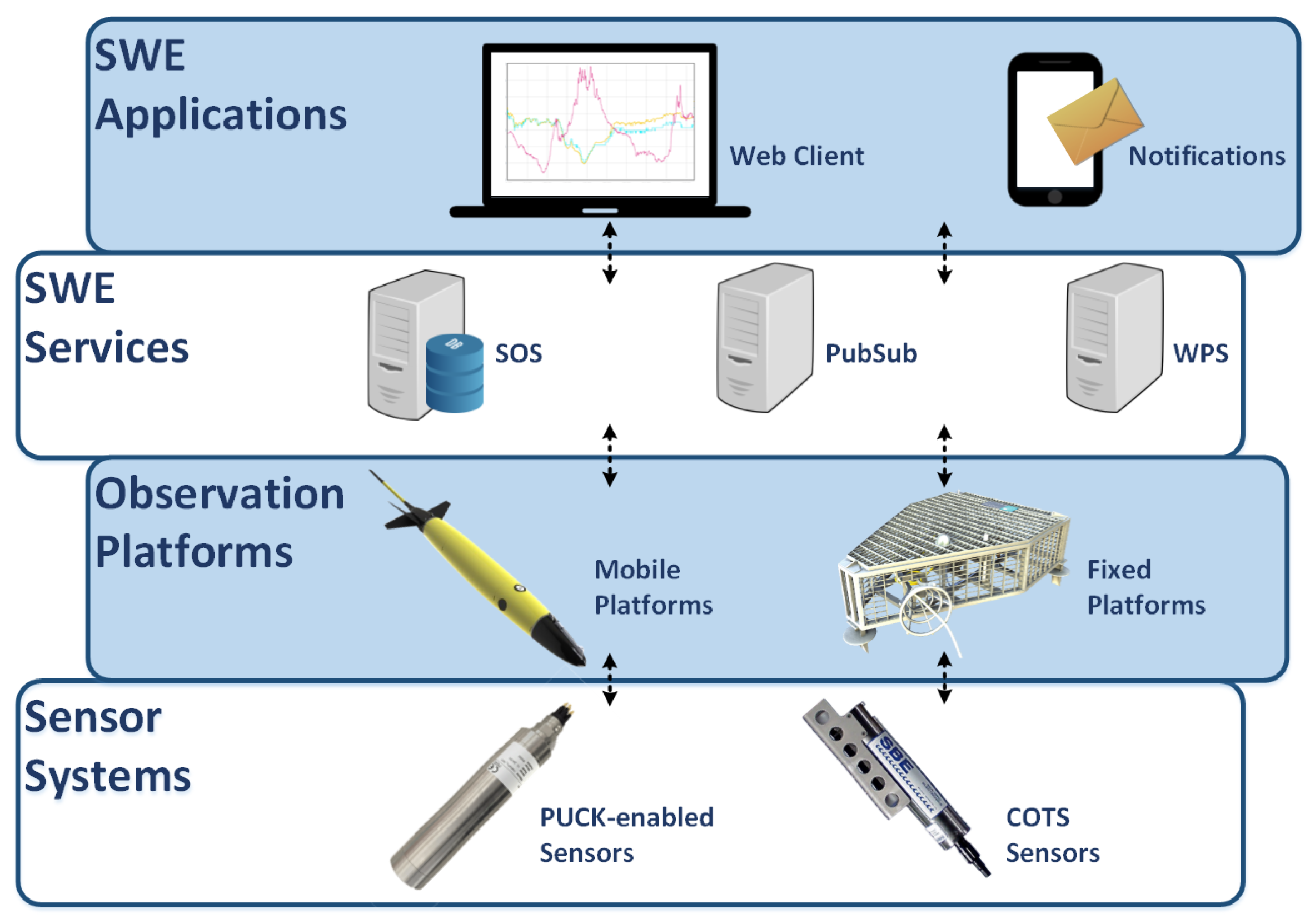
2. Sensor Integration into Observation Platforms
2.1. Requirement Analysis
- Sensor Detection: Detect a new sensor when it is attached to an observation platform. The host platform controller should be able to detect a new sensor without human intervention.
- Sensor Identification: Obtain an unambiguous description of the sensor, including all the metadata to identify the sensor (unique ID, sensor model, etc.) and all information required to register the sensor to an existing Sensor Web server.
- Sensor Configuration: This requirement addresses all operations required before the platform can start retrieving data from a sensor. This includes establishing a communication link between the platform and the sensor and applying any configuration required by the sensor (i.e., activate a specific acquisition channel, set the sampling rate, etc.).
- Simple Measurements Operations: Those operations that are directly related to the retrieval of data. These operations may be actively querying the sensor for data or listening to data streams. Also knowledge of the data interface provided by the sensor is required in order to parse, process and store the data.
- Sensor Registration: Registering a sensor to existing Sensor Web server requires a considerable amount of metadata organized and structured in a coherent way, including physical parameters that are being measured (observable properties), computational representation of the real-world feature that is being measured (feature of interest), alongside with other sensor characteristics. Furthermore, the meaning of this metadata has to be made explicit and understandable by machines, thus, controlled vocabularies containing formal definitions shall be used [27].
- Data Ingestion: Once the sensor is registered, the data measured by this sensor has to be ingested to the server, where it will be archived.
- Resource Constrains: Any plug and play mechanism aimed to integrate sensors into marine data acquisition platforms should be able to work in low-bandwidth, low-power and computationally-constrained scenarios.
2.2. Protocols and Standards
2.2.1. OGC PUCK Protocol
2.2.2. Sensor Model Language
2.2.3. Sensor Observation Service
2.2.4. Observations and Measurements
2.2.5. Efficient XML Interchange
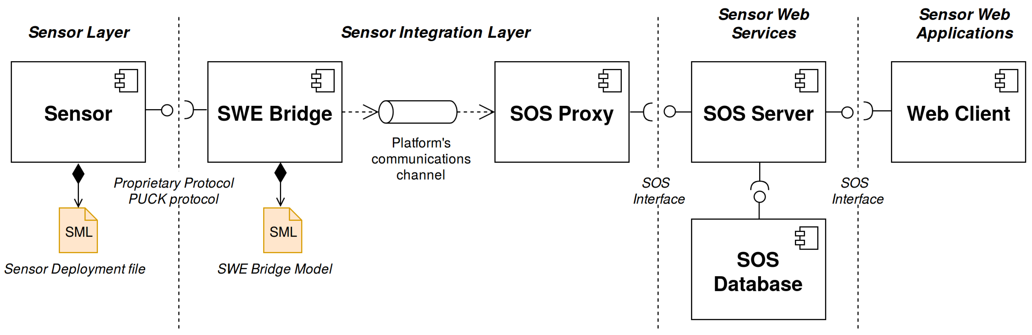
3. SWE-Based Acquisition Chain
3.1. Sensor
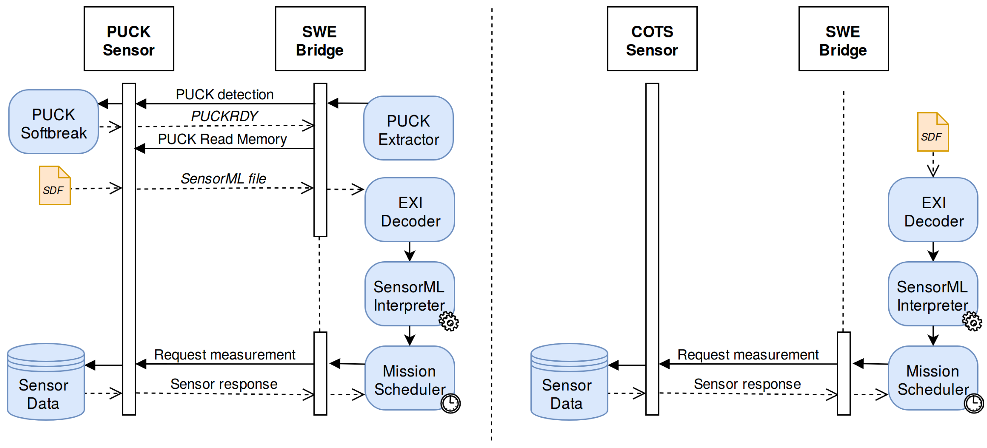
- COTS Sensors: Commercial off-the-shelf (COTS) sensors are commercially available devices without any particular enhancement in terms of interoperability.
- OGC PUCK-enabled Sensors: Sensors which implement the OGC PUCK protocol.
- Virtual Instruments: Software components that merge or process data from different sources, generating new data sets accessible through a communication interface.
3.2. SWE Bridge
3.3. SOS Proxy
3.4. SOS Server
3.5. Web Client
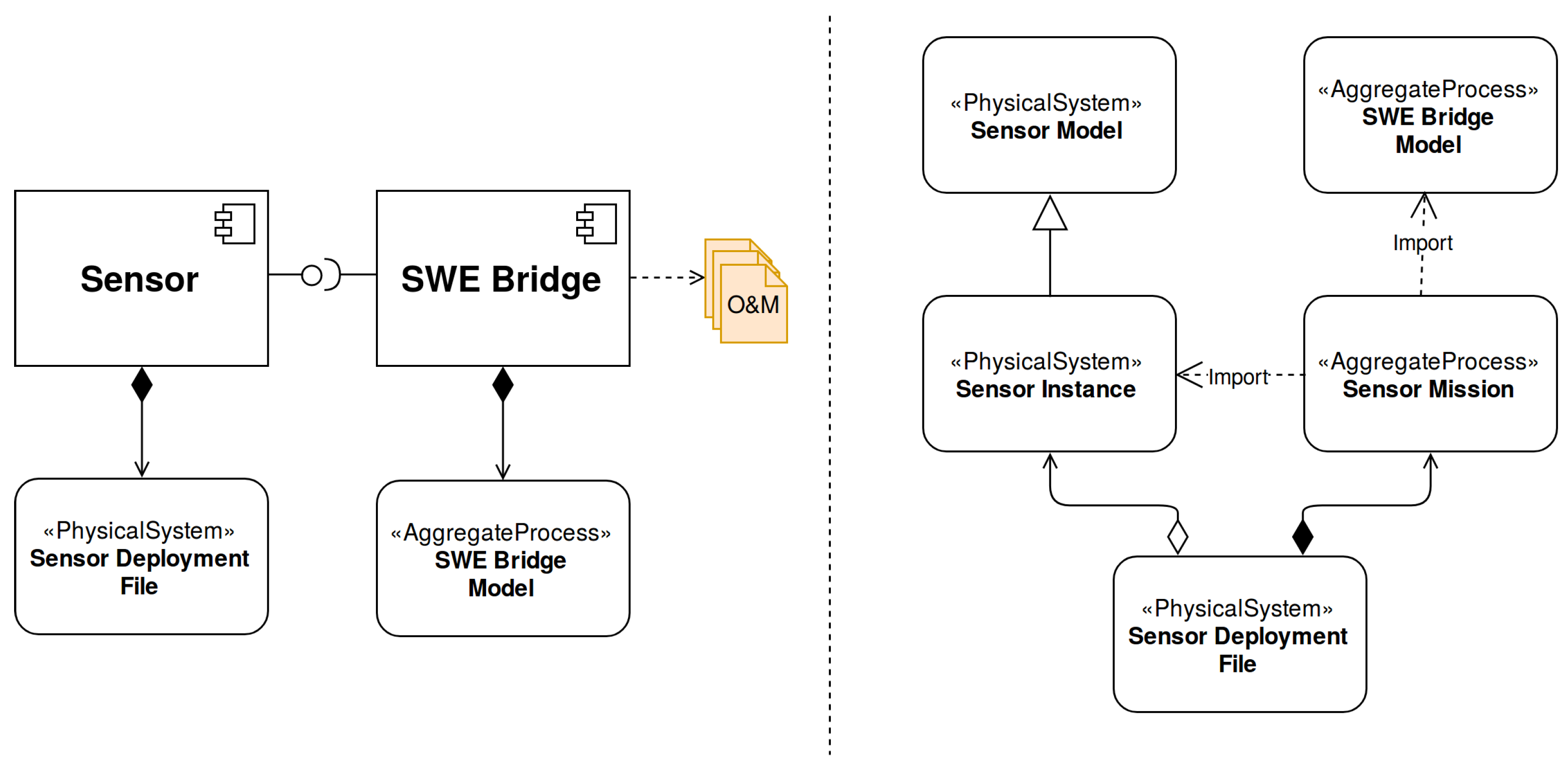
4. Sensor Deployment Files
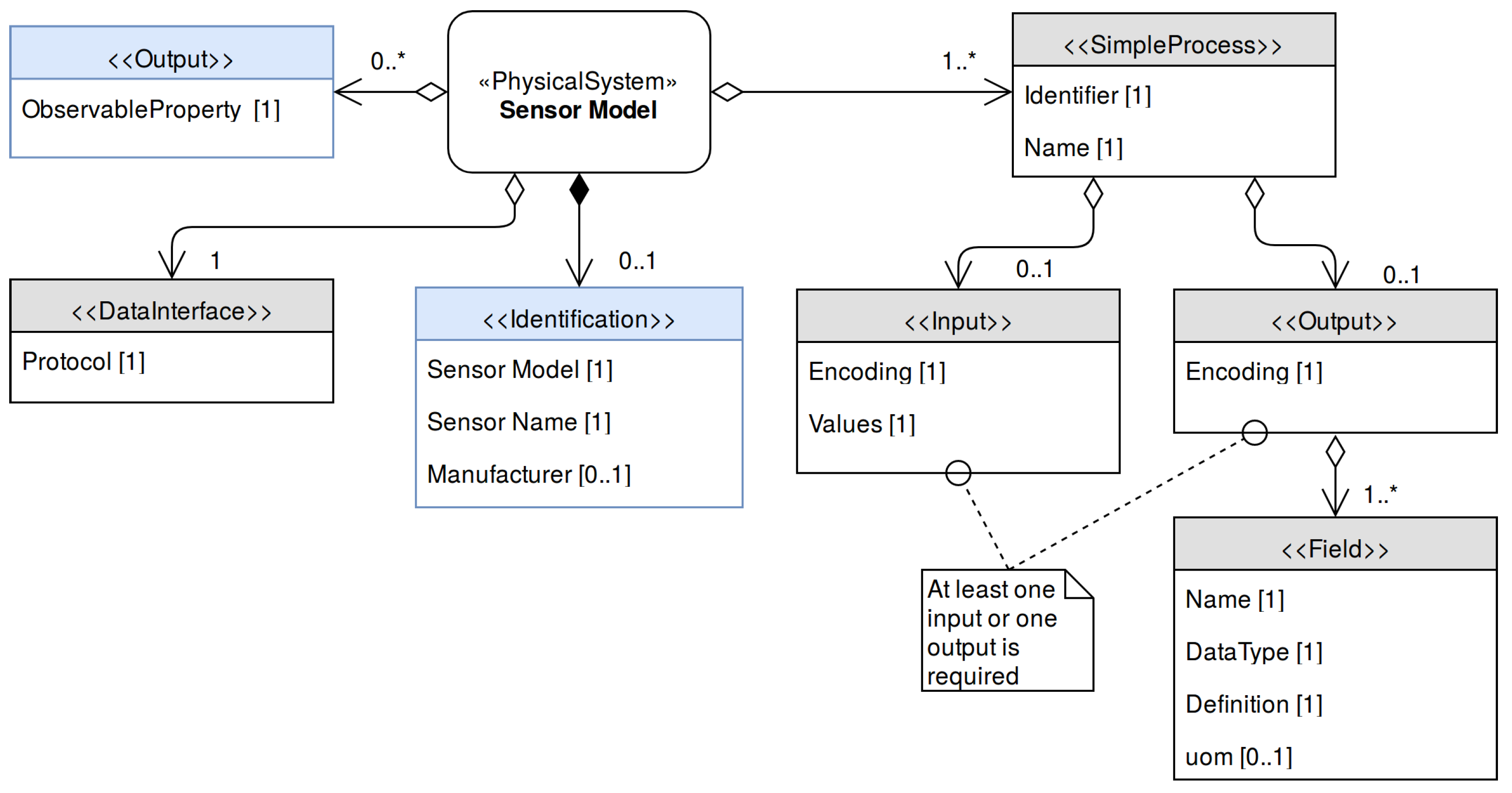
- Identification: Provide the required identifiers for the sensor, such as unique ID, model, name, manufacturer, etc. Define which physical parameters is the sensor able to measure.
- Communications Interface: An unambiguous and accurate description of the sensor’s communication interface to allow an interpreter software to automatically establish a communication link without any a priory information about of the sensor.
- Communication protocol: Set of commands required to operate the instrument. This includes configuration commands and measuring operations, as well as a description of the encoding of the sensor outputs.
- Operation: Detailed description of the sensor operation, including which operations need to be executed, in which order, which post-processing procedures will be applied to the sensor data and how this data will be stored.
4.1. Sensor Model
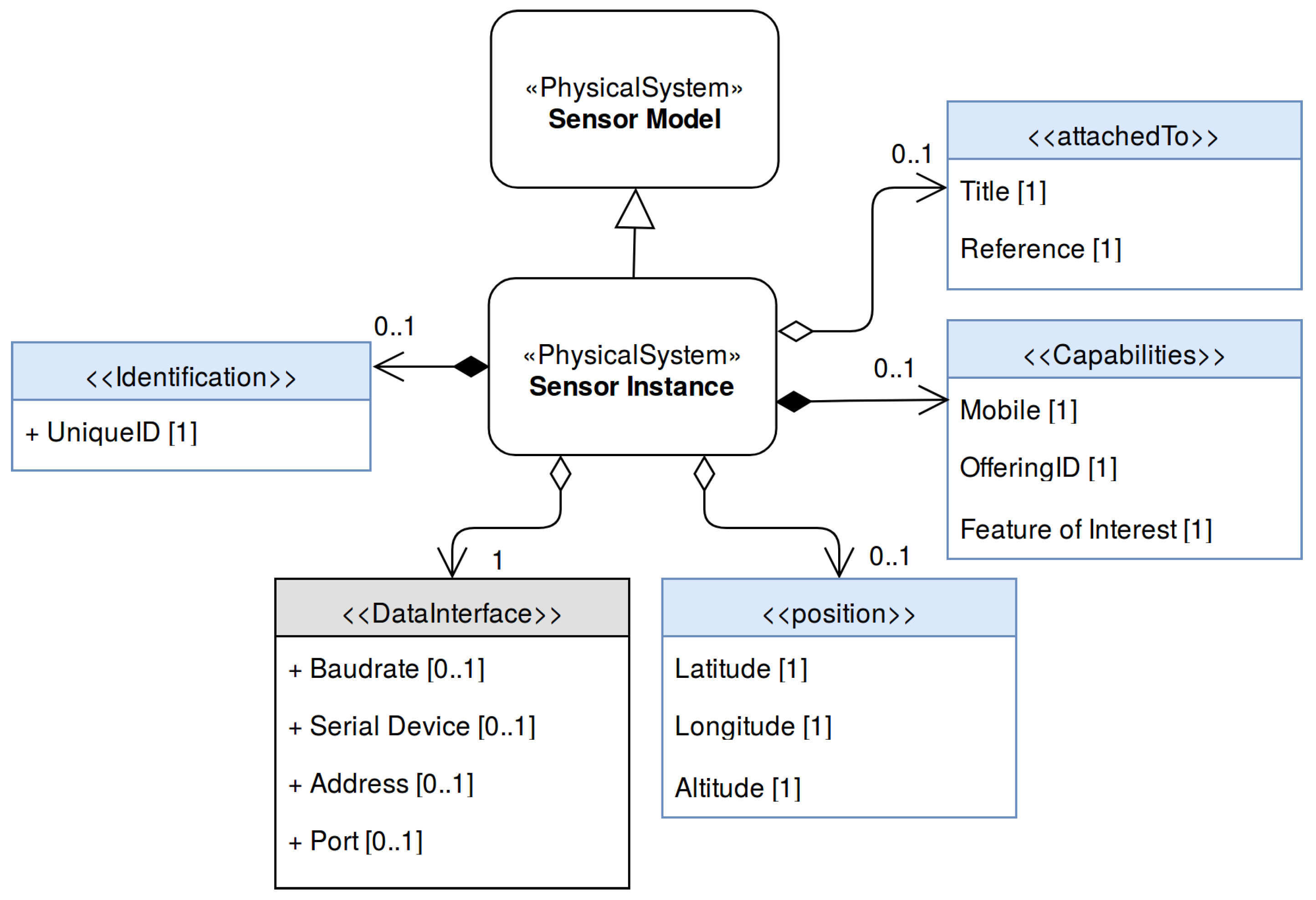
4.2. Sensor Instance
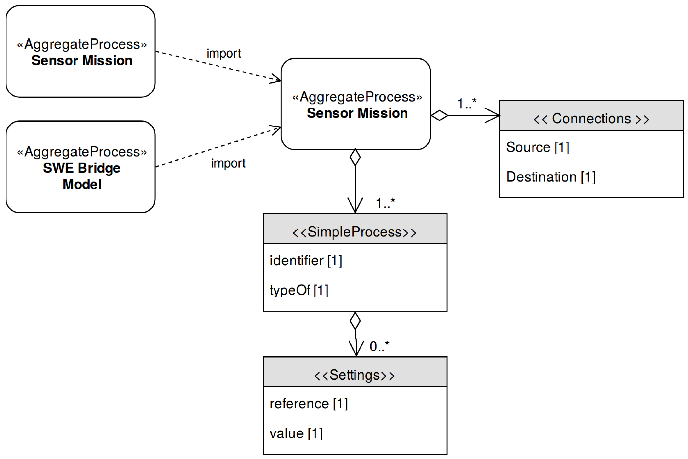
4.3. Sensor Mission
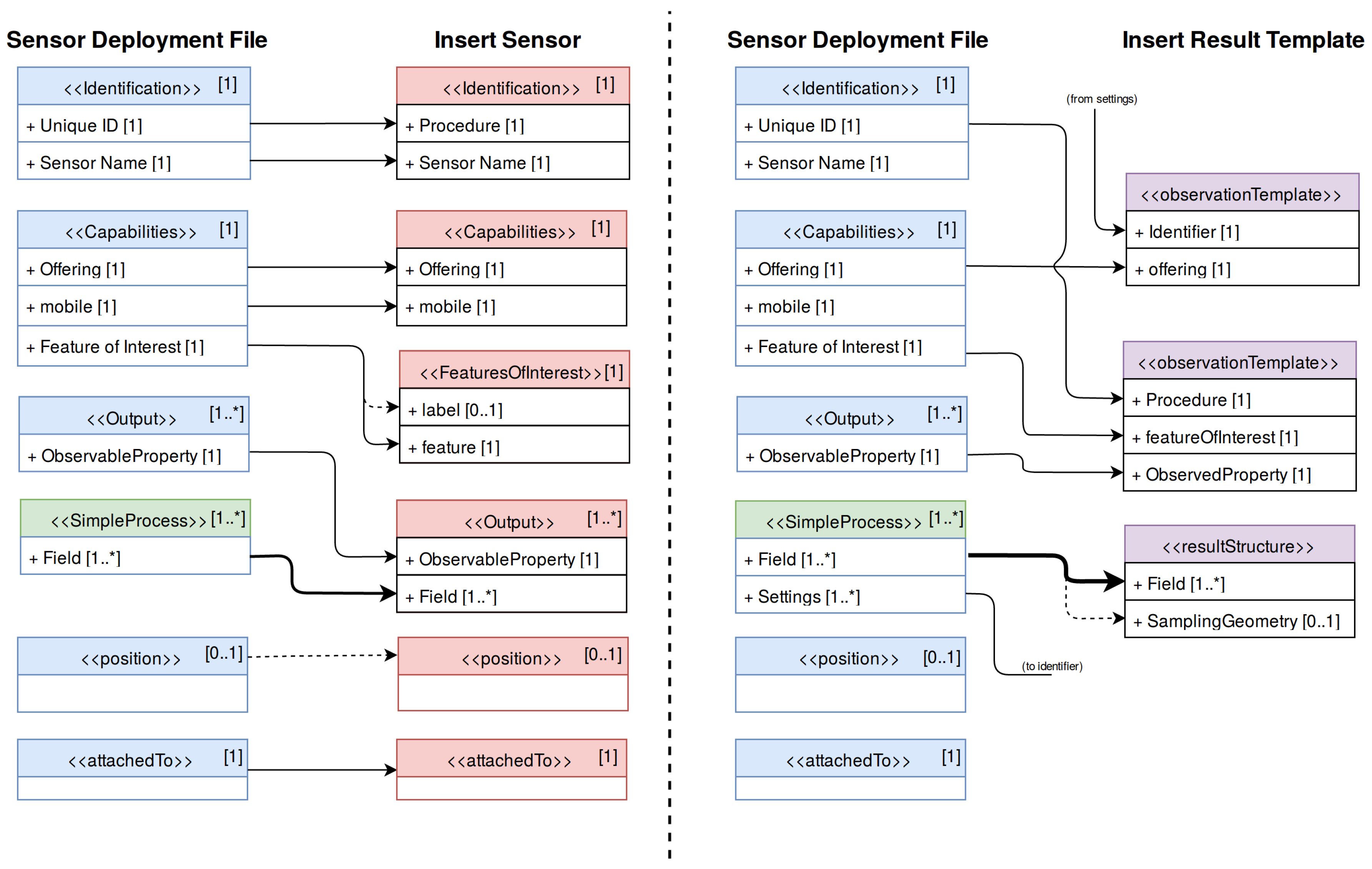
4.4. Sensor Deployment Files and SOS Registration
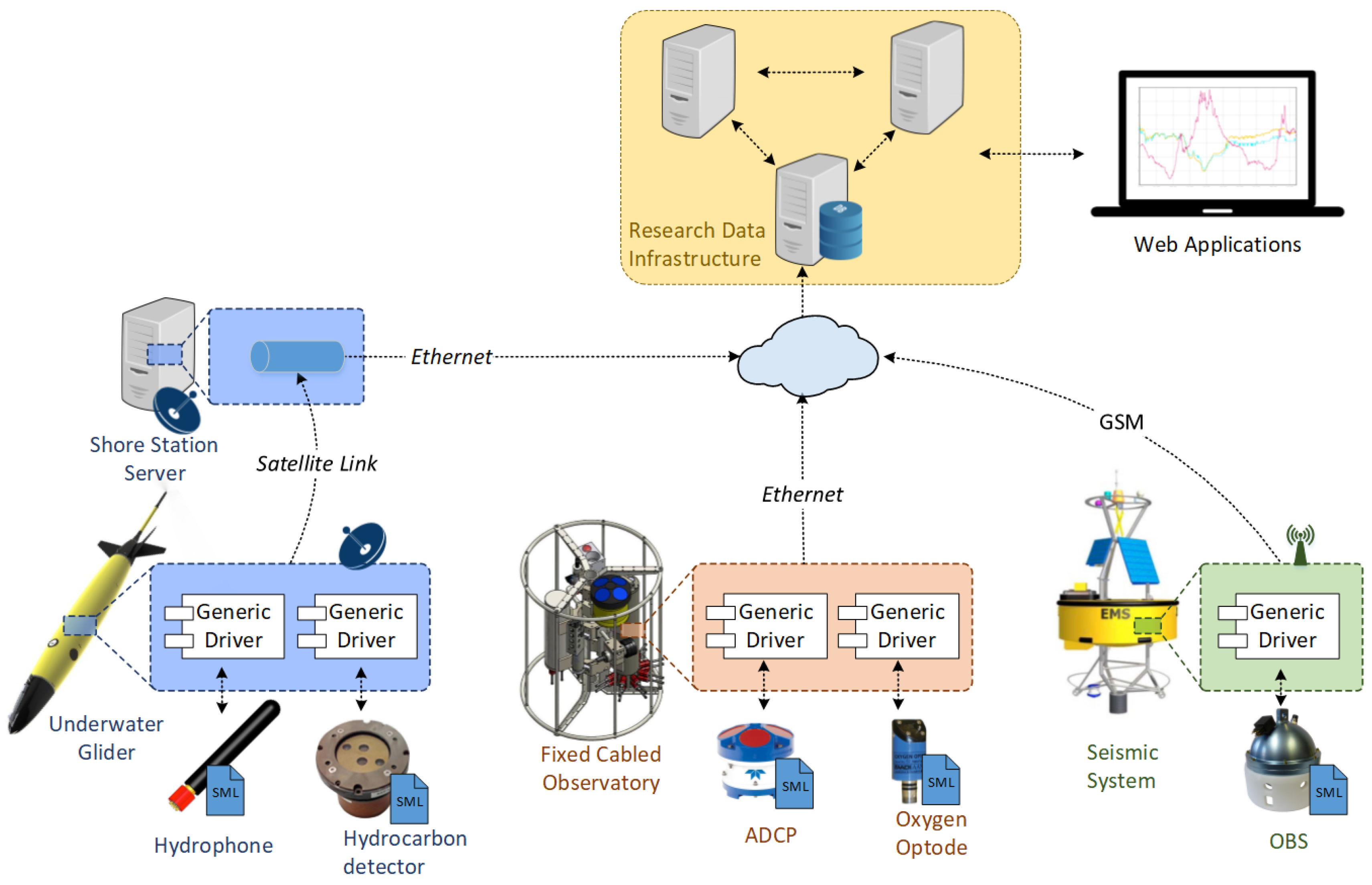
5. Standards-Based Universal Acquisition Middleware
5.1. Background
- Plug and play sensor discovery: The middleware shall be able discover and communicate with sensors connected on-the-fly, without any prior knowledge about these sensors.
- Standards-based configuration: The middleware shall be able to interpret SDFs and setup an acquisition process based on the information contained in these files.
- Cross-platform design: The middleware shall be deployable in a maximum number of platforms, regardless of their particular hardware and software architecture.
- Minimum resource requirements: Due to the intrinsic constraints of some observation platforms, the usage of hardware and software resources has to be reduced as much as possible (RAM usage, bandwidth, etc.).
- Standard compliance: Such a middleware shall be described through SensorML files to allow systems to automatically understand its role and capabilities.
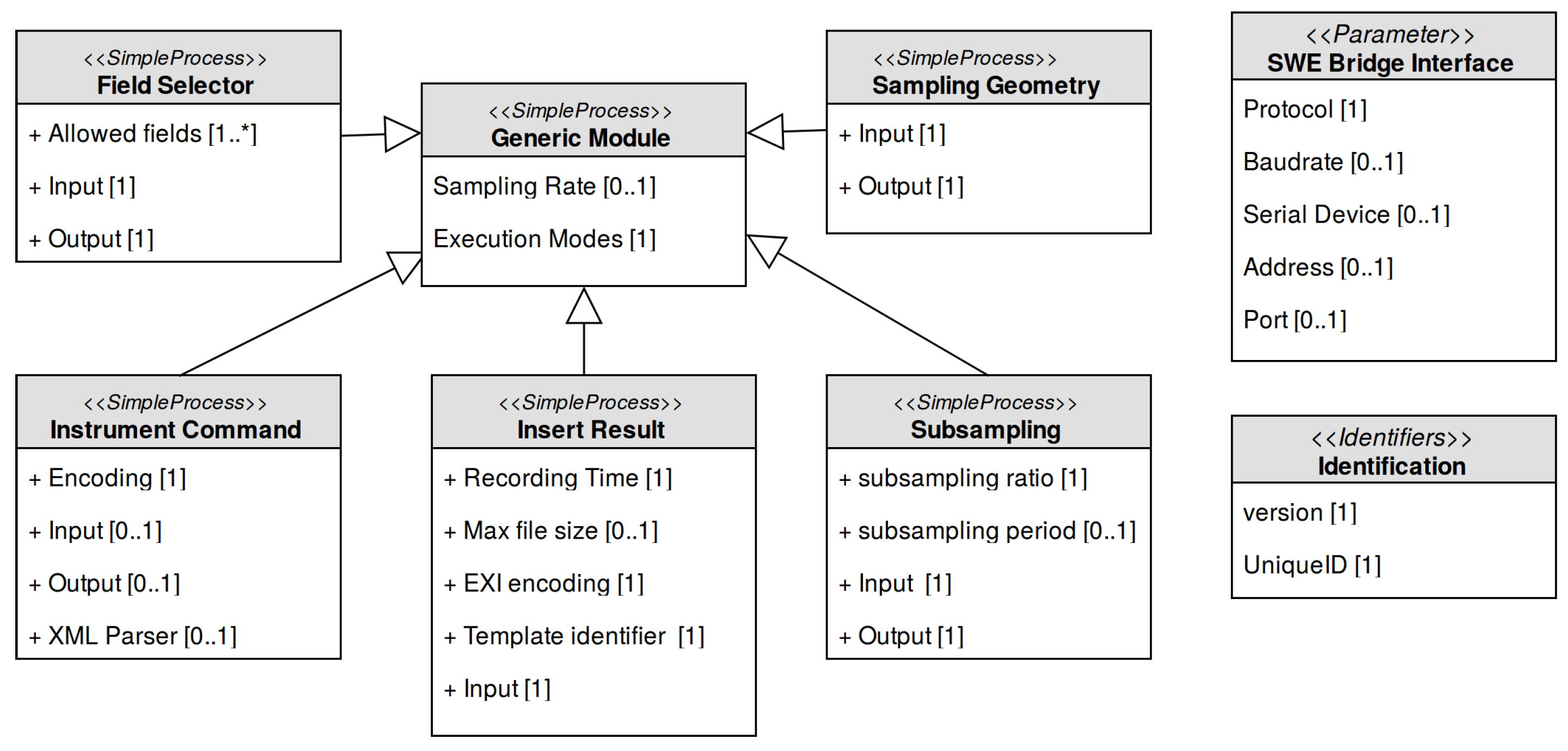
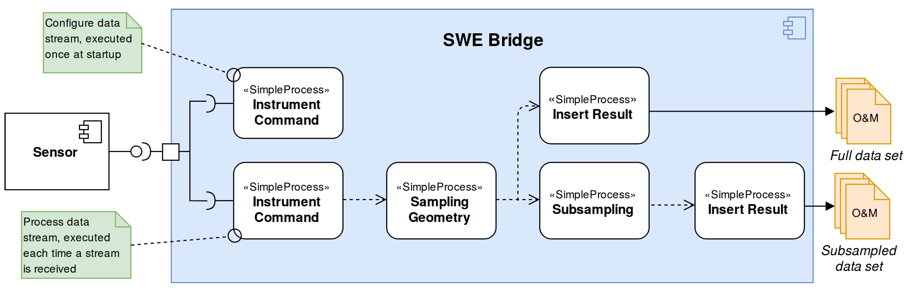
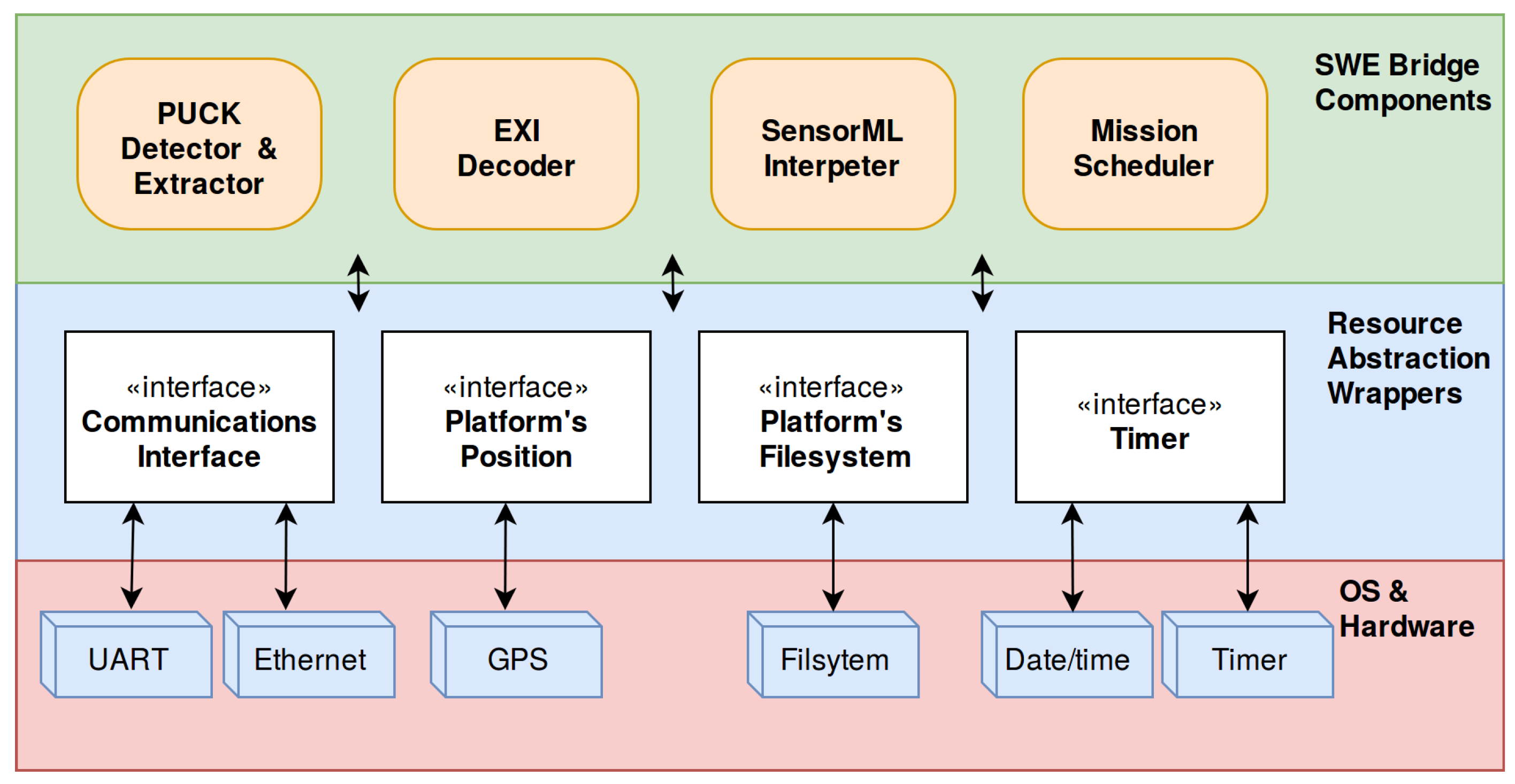
5.2. SWE Bridge Model
- Instrument Command: This module provides a unified process to communicate with a sensor. Depending on the configuration, this module can be used to send any kind of commands and/or receive sensor data.
- Field Selector: This module allows to filter the response of a sensor, selecting the desired information and discarding the rest.
- Subsampling: This module allows to create subsampled data sets. It is especially useful in platforms with severe communication constraints, where a subsampled data set is transmitted in real time and a full data set is stored locally.
- Sampling Geometry: This module adds the platform position to a data structure, correlating sensor data with the platform’s coordinates.
- Insert Result: This module stores the incoming data to standard O&M files, encoded in XML or EXI.
5.3. Implementation
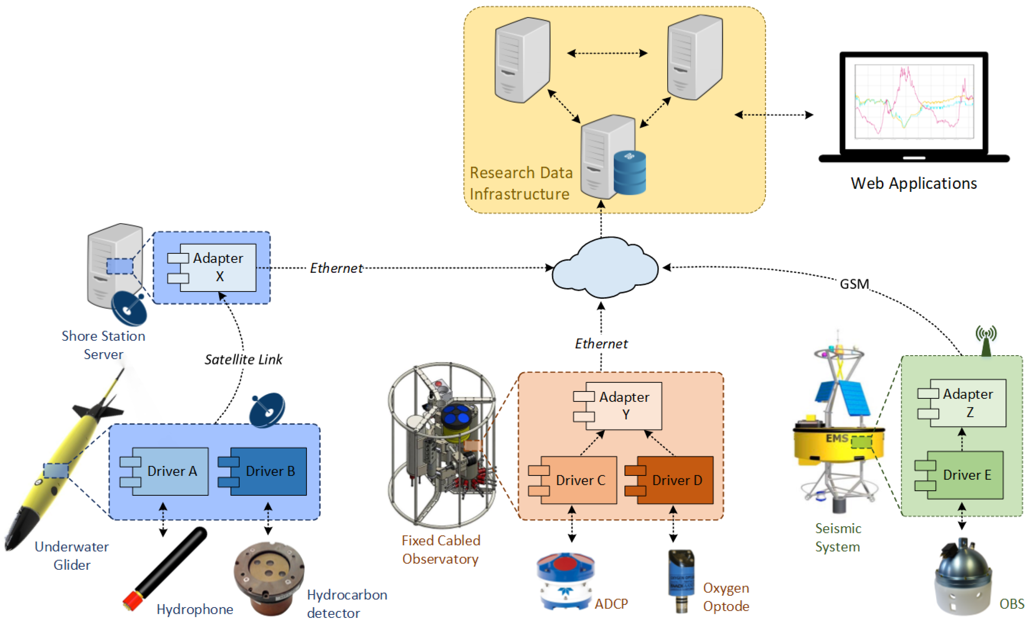
6. Use Cases
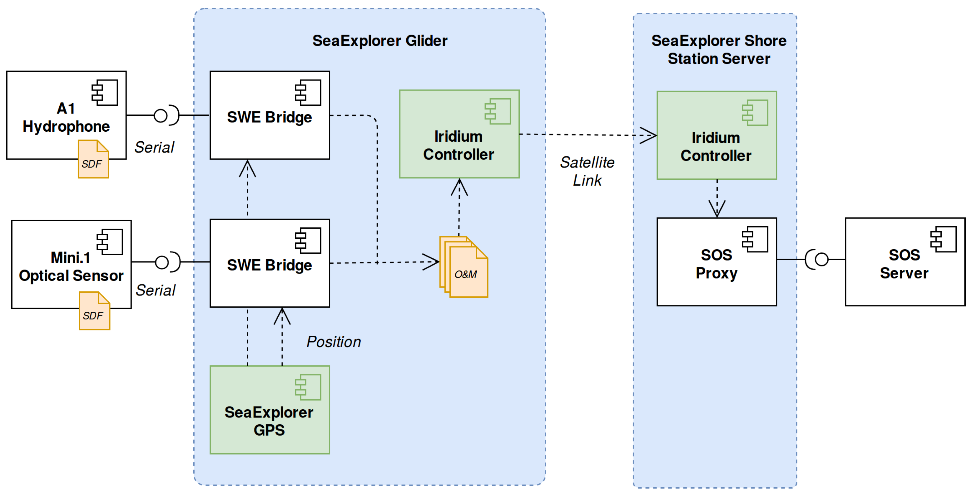
6.1. NeXOS Project
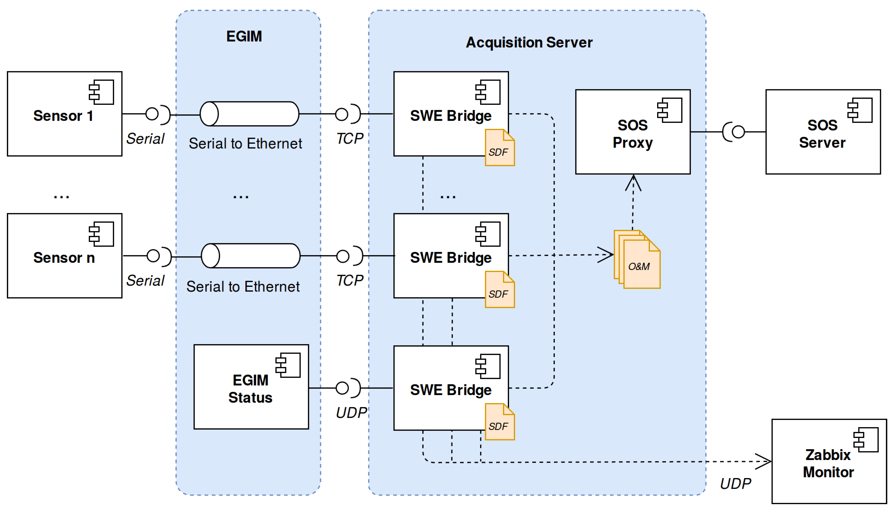
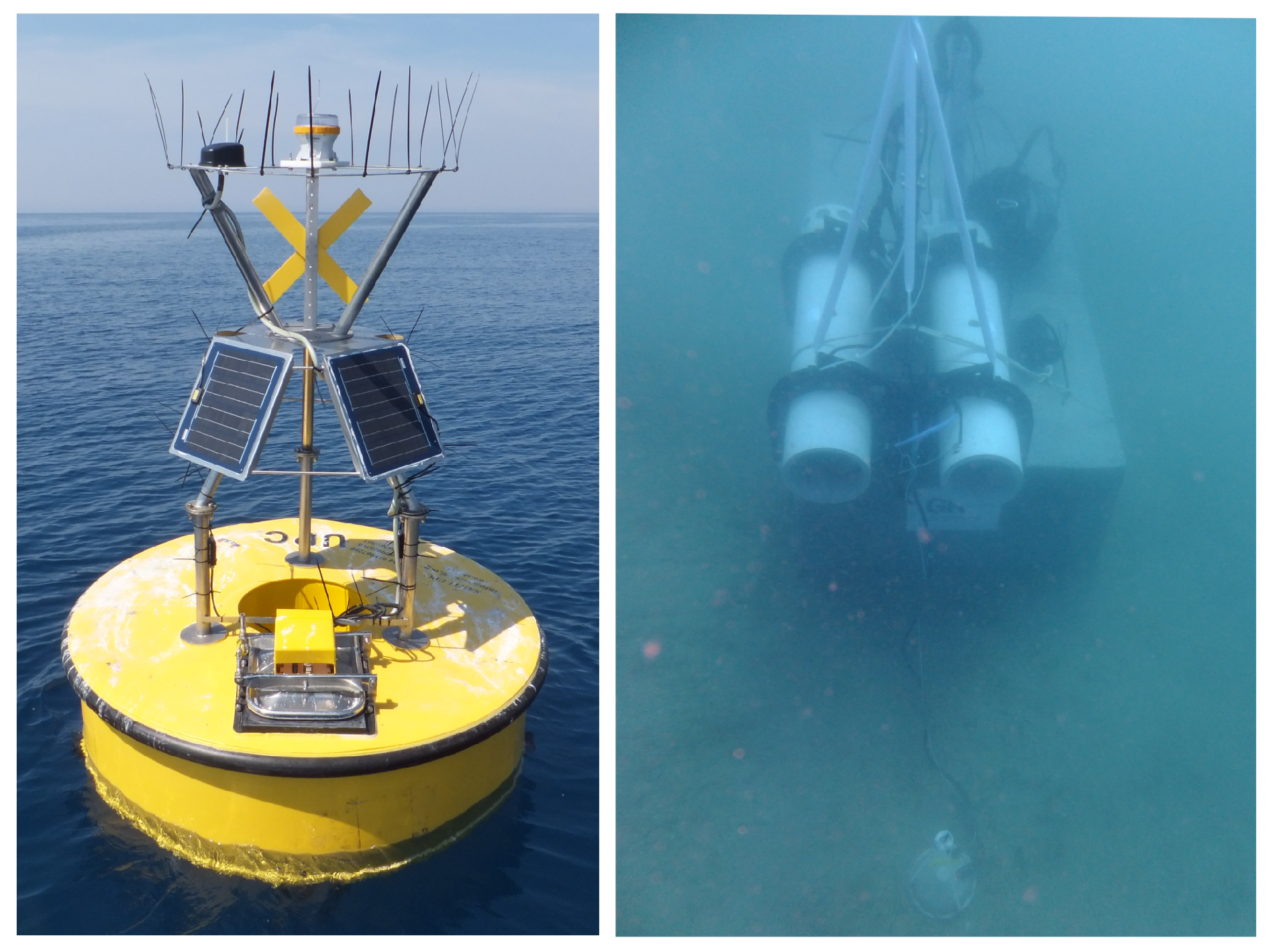
6.2. EMSODEV Project
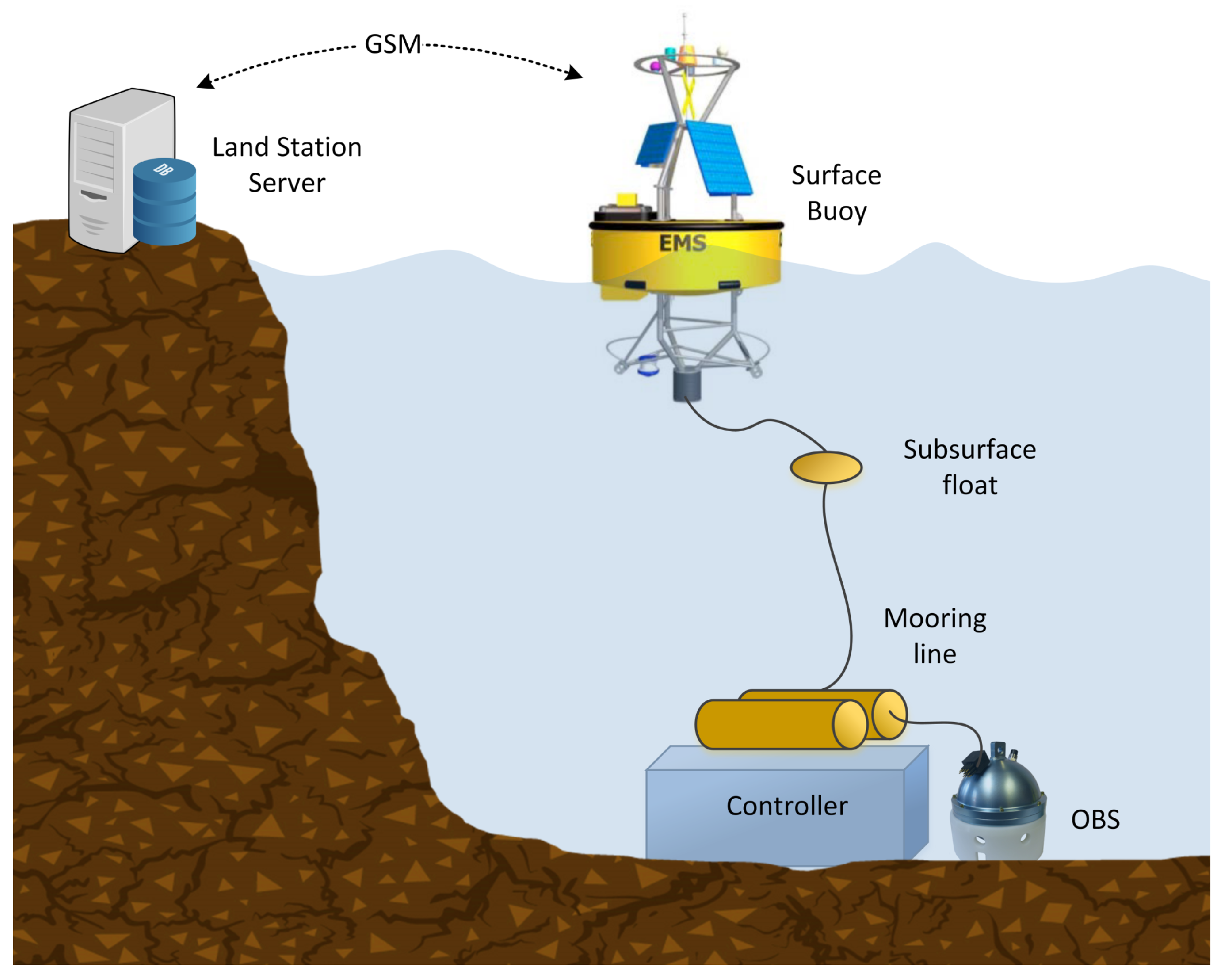
6.3. INTMARSIS Project
6.4. SWE Bridge Performance
7. Conclusions and Future Work
Acknowledgments
Author Contributions
Conflicts of Interest
Abbreviations
| OGC | Open Geospatial Consortium |
| SWE | Sensor Web Enablement |
| O&M | Observations and Measurements |
| SOS | Sensor Observation Service |
| SensorML | Sensor Model Language |
| EXI | Efficient XML Interchange |
| SDF | Sensor Deployment File |
| COTS | Commercial off-the-shelf |
References
- Reed, C.; Botts, M.; Davidson, J.; Percivall, G. OGC Sensor Web Enablement: Overview and High Level Architecture. GeoSens. Netw. 2008, 4540, 175–190. [Google Scholar]
- Bröring, A.; Echterhoff, J.; Jirka, S.; Simonis, I.; Everding, T.; Stasch, C.; Liang, S.; Lemmens, R. New generation Sensor Web Enablement. Sensors 2011, 11, 2652–2699. [Google Scholar] [CrossRef] [PubMed]
- Bröring, A.; Maué, P.; Janowicz, K.; Nüst, D.; Malewski, C. Semantically-enabled sensor Plug & Play for the Sensor Web. Sensors 2011, 11, 7568–7605. [Google Scholar] [PubMed]
- Broring, A.; Foerster, T.; Jirka, S. Interaction patterns for bridging the gap between sensor networks and the Sensor Web. In Proceedings of the Communications Workshops 2010 8th IEEE International Conference on Pervasive Computing and Communications, Mannheim, Germany, 29 March–2 April 2010; pp. 732–737. [Google Scholar]
- Del Rio, J.; Toma, D.M.; O’Reilly, T.C.; Broring, A.; Dana, D.R.; Bache, F.; Headley, K.L.; Manuel-Lazaro, A.; Edgington, D.R. Standards-based plug & work for instruments in ocean observing systems. IEEE J. Ocean. Eng. 2014, 39, 430–443. [Google Scholar]
- Geraci, A.; Katki, F.; McMonegal, L.; Meyer, B.; Porteous, H. IEEE Standard Computer Dictionary. A Compilation of IEEE Standard Computer Glossaries. IEEE Std 610 1991, 1. [Google Scholar] [CrossRef]
- Dawes, N.; Kumar, K.A.; Michel, S.; Aberer, K.; Lehning, M. Sensor metadata management and its application in collaborative environmental research. In Proceedings of the 4th IEEE International Conference on eScience, Indianapolis, IN, USA, 10–12 December 2008; pp. 143–150. [Google Scholar]
- Sheth, A.; Henson, C.; Sahoo, S.S. Semantic sensor web. IEEE Internet Comput. 2008, 12, 78–83. [Google Scholar] [CrossRef]
- Walter, K.; Nash, E. Coupling Wireless Sensor Networks and the Sensor Observation Service—Bridging the Interoperability Gap. In Proceedings of the 12th AGILE International Conference on Geographic Information Science, Hannover, Germany, 2–5 June 2009; pp. 1–9. [Google Scholar]
- Fairgrieve, S.M.; Makuch, J.A.; Falke, S.R. PULSENet: An implementation of sensor web standards. In Proceedings of the 2009 International Symposium on Collaborative Technologies and Systems, Baltimore, MD, USA, 18–22 May 2009; pp. 64–75. [Google Scholar]
- Geipel, J.; Jackenkroll, M.; Weis, M.; Claupein, W. A Sensor Web-Enabled Infrastructure for Precision Farming. ISPRS Int. J. Geo-Inf. 2015, 4, 385–399. [Google Scholar] [CrossRef]
- Sawant, S.A.; Adinarayana, J.; Durbha, S.S. KrishiSense: A semantically aware web enabled wireless sensor network system for precision agriculture applications. In Proceedings of the International Geoscience and Remote Sensing Symposium (IGARSS), Quebec City, QC, Canada, 13–18 July 2014; pp. 4090–4093. [Google Scholar]
- Kotsev, A.; Schade, S.; Craglia, M.; Gerboles, M.; Spinelle, L.; Signorini, M. Next generation air quality platform: Openness and interoperability for the internet of things. Sensors 2016, 16, 403. [Google Scholar] [CrossRef] [PubMed] [Green Version]
- Kotsev, A.; Pantisano, F.; Schade, S.; Jirka, S. Architecture of a service-enabled sensing platform for the environment. Sensors 2015, 15, 4470–4495. [Google Scholar] [CrossRef] [PubMed] [Green Version]
- Bray, T.; Paoli, J.; Sperberg-McQueen, C.M.; Maler, E.; Yergeau, F. Extensible Markup Language (XML). World Wide Web J. 1997, 2, 27–66. [Google Scholar]
- Tamayo, A.; Granell, C.; Huerta, J. Using SWE standards for ubiquitous environmental sensing: A performance analysis. Sensors 2012, 12, 12026–12051. [Google Scholar] [CrossRef] [Green Version]
- Schneider, J.; Kamiya, T.; Peintner, D.; Kyusakov, R. Efficient XML Interchage (EXI) Format 1.0 (Second Edition). Available online: https://www.w3.org/TR/exi/ (accessed on 9 October 2017).
- Song, E.Y.; Lee, K. Understanding IEEE 1451 - Networked smart transducer interface standard—What is a smart transducer? IEEE Instrum. Meas. Mag. 2008, 11, 11–17. [Google Scholar] [CrossRef]
- Song, E.Y.; Lee, K.B. Service-oriented sensor data interoperability for IEEE 1451 smart transducers. In Proceedings of the IEEE Intrumentation and Measurement Technology Conference ( I2MTC), Singapore, 5–7 May 2009; pp. 1049–1054. [Google Scholar]
- Liang, S.; Huang, C.-Y.; Khalafbeigi, T. OGC SensorThings API-Part 1: Sensing; Open Geospatial Consortium: Wayland, MA, USA, 2012; Technical Report. [Google Scholar]
- Gigan, G.; Atkinson, I. Sensor Abstraction Layer: A unique software interface to effectively manage sensor networks. In Proceedings of the Intelligent Sensors, Sensor Networks and Information Processing (ISSNIP), Melbourne, Australia, 3–6 December 2007; pp. 479–484. [Google Scholar]
- Broering, A.; Below, S.; Foerster, T. Declarative sensor interface descriptors for the sensor web. In Proceedings of the WebMGS 2010: 1st International Workshop on Pervasive Web Mapping, Geoprocessing and Services, Como, Italy, 26–27 August 2010; pp. 26–32. [Google Scholar]
- Trevathan, J.; Johnstone, R.; Chiffings, T.; Atkinson, I.; Bergmann, N.; Read, W.; Theiss, S.; Myers, T.; Stevens, T. SEMAT—The next generation of inexpensive marine environmental monitoring and measurement systems. Sensors 2012, 12, 9711–9748. [Google Scholar] [CrossRef] [PubMed]
- Bröring, A.; Bache, F.; Bartoschek, T.; van Elzakker, C.P.J.M. The SID Creator: A Visual Approach for Integrating Sensors with the Sensor Web. Lect. Notes Geoinf. Cartogr. 2011, 143–162. [Google Scholar]
- Jazayeri, M.A.; Liang, S.H.L.; Huang, C.Y. Implementation and evaluation of four interoperable open standards for the internet of things. Sensors 2015, 15, 24343–24373. [Google Scholar] [CrossRef] [PubMed]
- Díaz, L.; Bröring, A.; McInerney, D.; Libertá, G.; Foerster, T. Publishing sensor observations into Geospatial Information Infrastructures: A use case in fire danger assessment. Environ. Model. Softw. 2013, 48, 65–80. [Google Scholar] [CrossRef]
- Bröring, A.; Janowicz, K.; Stasch, C.; Kuhn, W. Semantic challenges for sensor plug and play. In Proceedings of the International Symposium on Web and Wireless Geographical Information Systems, Maynooth, Ireland, 7–8 December 2009; Volume 5886 LNCS, pp. 72–86. [Google Scholar]
- O’Reilly, T. OGC® PUCK Protocol Standard Version 1.4; Technical Report; Open Geospatial Consortium: Wayland, MA, USA, 2012. [Google Scholar]
- Botts, M.; Robin, A. OGC SensorML: Model and XML Encoding Standard; Technical Report OGC 12-000; Open Geospatial Consortium: Wayland, MA, USA, 2014. [Google Scholar]
- Jirka, S. The Marine Profiles for OGC Sensor Web Enablement Standards Team. In Proceedings of the EGU General Assembly 2016, Vienna, Austria, 23–28 April 2016; Volume 18, p. 14690. [Google Scholar]
- Bröring, A.; Stasch, C.; Echterhoff, J. OGC Sensor Observation Service; Technical Report; Open Geospatial Consortium: Wayland, MA, USA, 2012. [Google Scholar]
- Cox, S. Geographic Information: Observations and Measurements; Technical Report; Open Geospatial Consortium: Wayland, MA, USA, 2013. [Google Scholar]
- SOS Proxy (java). Available online: https://bitbucket.org/swebridgedevelopment/sos-proxy-java (accessed on 25 October 2017).
- SOS Proxy (Bash). Available online: https://bitbucket.org/swebridgedevelopment/sos_proxy (accessed on 24 October 2017).
- 52° North Sensor Observation Service (SOS). Available online: https://github.com/52North/SOS (accessed on 24 October 2017).
- Helgoland. Available online: https://github.com/52North/helgoland (accessed on 25 October 2017).
- Sensor Deployment File Repository. Available online: https://bitbucket.org/swebridgedevelopment/sdfs (accessed on 2 December 2017).
- Robin, A. OGC SWE Common Data Model Encoding Standard; Technical Report; Open Geospatial Consortium: Wayland, MA, USA, 2011. [Google Scholar]
- SWE Bridge Model. Available online: https://www.upc.edu/cdsarti/OBSEA/SWE/files/swe_bridge/model/swe_bridge_model.xml (accessed on 6 November 2017).
- SWE Bridge. Available online: https://bitbucket.org/swebridgedevelopment/swebridge (accessed on 24 October 2017).
- Kyusakov, R.; Pereira, P.P.; Eliasson, J.; Delsing, J. EXIP: A Framework for Embedded Web Development. ACM Trans. Web 2014, 8, 23:1–23:29. [Google Scholar] [CrossRef]
- Delory, E.; Castro, A.; Waldmann, C.; Rolin, J.F.; Woerther, P.; Gille, J.; Del Rio, J.; Zielinski, O.; Golmen, L.; Hareide, N.R.; et al. Objectives of the NeXOS project in developing next generation ocean sensor systems for a more cost-efficient assessment of ocean waters and ecosystems, and fisheries management. In Proceedings of the MTS/IEEE OCEANS 2014: Oceanic Engineering Society (OES) and Marine Technology Society, Taipei, Taiwan, 7–10 April 2014. [Google Scholar]
- Toma, D.M.; Del Rio, J.; Jirka, S.; Delory, E.; Pearlman, J.; Waldmann, C. NeXOS smart electronic interface for sensor interoperability. In Proceedings of the MTS/IEEE OCEANS 2015: Discovering Sustainable Ocean Energy for a New World, Genova, Italy, 18–21 May 2015. [Google Scholar]
- Claustre, H.; Beguery, L. SeaExplorer Glider Breaks Two World Records. Sea Technol. 2014, 55, 19–21. [Google Scholar]
- Favali, P.; Dañobeitia, J.; Beranzoli, L.; Rolin, J.F.; Lykousis, V.; Ruhl, H.A.; Paul, G.; Piera, J.; Huber, R.; del Río, J.; et al. European Multidisciplinary and Water-Column Observa tory—European Research Infrastructure Consortium (EMSO ERIC): Challenges and opportunities for Strategic European Marine Sciences. In Proceedings of the 7th International Workshop on Marine Technology, Barcelona, Spain, 26–28 October 2016; pp. 100–103. [Google Scholar]
- Toma, D.M.; Del Rio, J.; Cadena, J.; Bghiel, I.; Martínez, E.; Nogueras, M.; Garcia, Ó.; Dañobeitia, J.; Sorribas, J.; Casas, R.; et al. OGC SWE-based data acquisition system development for EGIM on EMSODEV EU project. In Proceedings of the Geospatial Sensor Webs Conference, Münster, Germany, 29–31 August 2016; Volume 1762, pp. 1–5. [Google Scholar]
- Zabbix. Available online: https://www.zabbix.com (accessed on 15 November 2017).
- Aguzzi, J.; Mànuel, A.; Condal, F.; Guillén, J.; Nogueras, M.; del Rio, J.; Costa, C.; Menesatti, P.; Puig, P.; Sardà, F.; et al. The new seafloor observatory (OBSEA) for remote and long-term coastal ecosystem monitoring. Sensors 2011, 11, 5850–5872. [Google Scholar] [CrossRef] [PubMed] [Green Version]
- Toma, D.M.; Artero, C.; Del Río, J.; Trullols, E.; Roset, X. Near Real-Time Determination of Earthquake Source Parameters from the Coastal Ocean. In Proceedings of the 7th International Workshop on Marine Technology, Barcelona, Spain, 26–028 October 2016. [Google Scholar]
- Real-Time Oceanography with Inductive Moorings and Inductive Modem Module. Available online: http://www.seabird.com/sites/default/files/documents/AppNote92Oct16.pdf (accessed on 6 October 2017).
- Massif: A Heap Profiler. Available online: http://valgrind.org/docs/manual/ms-manual.html (accessed on 28 November 2017).


| Sensor Type | Sensor Name | Manufacturer | Communication Link |
|---|---|---|---|
| CTD | SBE 37 | SeaBird Electronics | TCP/IP |
| Tsunami Meter | SBE 54 | SeaBird Electronics | TCP/IP |
| Oxygen Optode | Aanderaa 4831 | Aanderaa | TCP/IP |
| Turbidimeter | Eco NTU | Wetlabs | TCP/IP |
| ADCP | Workhorse | Teledyne | TCP/IP |
| Hydrophone | icListen | Ocean Sonics | FTP |
| EGIM Internal Stuatus | EGIM | EMSODEV Consortium | UDP |
| Processor Architecture | ARM 7 |
| Processor Speed | 900 MHz |
| Number of Cores | 4 |
| RAM memory | 1 GB |
| Operating System | Raspbian Jessie Lite (version July 2017) |
| Sensor Name | Sensor Parameters | SWE Bridge Performance | ||||||
|---|---|---|---|---|---|---|---|---|
| Protocol | Stream (bytes) | Period (s) | SDF Size (bytes) | Max Heap (kBytes) | Avg Heap (kBytes) | Avg Stack (kBytes) | CPU Load (KIPS) | |
| A1 | Serial | 61 | 1 | 3158 | 40.05 | 13.26 | 1.631 | 35.23 |
| Mini.1 | Serial | 68 | 1 | 2451 | 36.63 | 10.96 | 1.568 | 34.50 |
| Aanderaa 4831 | TCP | 80 | 1 | 3440 | 38.36 | 10.93 | 1.029 | 88.36 |
| Workhorse | TCP | 688 | 60 | 9431 | 63.66 | 36.43 | 0.830 | 78.23 |
| Eco NTU | TCP | 32 | 1 | 3290 | 36.93 | 9.53 | 0.892 | 78.26 |
| SBE 37 | TCP | 72 | 10 | 3429 | 37.91 | 10.22 | 0.740 | 68.39 |
| SBE 54 | TCP | 140 | 1 | 2769 | 35.56 | 8.05 | 0.895 | 87.35 |
| EGIM | UDP | 137 | 20 | 4477 | 42.57 | 14.70 | 0.691 | 68.03 |
| Seismic Data | UDP | 10 | 10 | 1728 | 29.96 | 5.84 | 0.692 | 63.61 |
| OBS Technical | UDP | 30 | 30 | 1764 | 29.76 | 6.02 | 0.683 | 63.75 |
| Buoy Status | UDP | 30 | 30 | 1764 | 29.96 | 6.32 | 0.685 | 63.89 |
© 2017 by the authors. Licensee MDPI, Basel, Switzerland. This article is an open access article distributed under the terms and conditions of the Creative Commons Attribution (CC BY) license (http://creativecommons.org/licenses/by/4.0/).
Share and Cite
Martínez, E.; Toma, D.M.; Jirka, S.; Del Río, J. Middleware for Plug and Play Integration of Heterogeneous Sensor Resources into the Sensor Web. Sensors 2017, 17, 2923. https://doi.org/10.3390/s17122923
Martínez E, Toma DM, Jirka S, Del Río J. Middleware for Plug and Play Integration of Heterogeneous Sensor Resources into the Sensor Web. Sensors. 2017; 17(12):2923. https://doi.org/10.3390/s17122923
Chicago/Turabian StyleMartínez, Enoc, Daniel M. Toma, Simon Jirka, and Joaquín Del Río. 2017. "Middleware for Plug and Play Integration of Heterogeneous Sensor Resources into the Sensor Web" Sensors 17, no. 12: 2923. https://doi.org/10.3390/s17122923