Analysis on Coupled Vibration of a Radially Polarized Piezoelectric Cylindrical Transducer

Shaanxi Key Laboratory of Ultrasonics, Institute of Applied Acoustics, Shaanxi Normal University, Xi’an 710119, China
*
Author to whom correspondence should be addressed.
Sensors 2017, 17(12), 2850; https://doi.org/10.3390/s17122850
Submission received: 11 October 2017
/
Revised: 25 November 2017
/
Accepted: 25 November 2017
/
Published: 8 December 2017
(This article belongs to the Section Physical Sensors)
Abstract
:Coupled vibration of a radially polarized piezoelectric cylindrical transducer is analyzed with the mechanical coupling coefficient method. The method has been utilized to analyze the metal cylindrical transducer and the axially polarized piezoelectric cylindrical transducer. In this method, the mechanical coupling coefficient is introduced and defined as the stress ratio in different directions. Coupled vibration of the cylindrical transducer is regarded as the interaction of the plane radial vibration of a ring and the longitudinal vibration of a tube. For the radially polarized piezoelectric cylindrical transducer, the radial and longitudinal electric admittances as functions of mechanical coupling coefficients and angular frequencies are derived, respectively. The resonance frequency equations are obtained. The dependence of resonance frequency and mechanical coupling coefficient on aspect ratio is studied. Vibrational distributions on the surfaces of the cylindrical transducer are presented with experimental measurement. On the support of experiments, this work is verified and provides a theoretical foundation for the analysis and design of the radially polarized piezoelectric cylindrical transducer.
1. Introduction
Radially polarized piezoelectric cylindrical transducers are widely used for filters, sensors, transmitters, and actuators, as well as in the field of nondestructive testing, medical diagnostics, underwater signaling, and ultrasonic motors [1,2,3,4,5]. For the theoretical analyses of the piezoelectric cylindrical transducer, Shuaijun Wang studied the ring-type and tube-type piezoelectric transducers polarized in the radial direction [6,7]. The vibration of the piezoelectric ring is along the plane radial direction, and the vibration of the piezoelectric tube is along the longitudinal direction. To increase the radiation area, augment the radiation range and realize the radial and longitudinal propagation at the same time, the large dimension and finite length piezoelectric cylindrical transducer is studied. Ebenezer described the piezoelectric thin shell theoretical model to analyze the radially polarized ceramic cylinder [8,9]. Larbi developed accurate piezoelectric shell finite elements of radially polarized multilayer piezoelectric hollow cylinder [10]. In these reports, the shell theory [11,12,13,14] and the membrane theory [15] are used, which neglect the radial stress and strain in piezoelectric equations [16]. It is more preferable for the analysis of the thin-wall transducer. When the thickness of the wall of the piezoelectric transducer is without limitation, the shell and the membrane theory are not recommended. In this case, the vibration of the piezoelectric cylindrical transducer is a complex coupled vibration, and the radial, circumferential, and axial stresses and strains are all considered.
To analyze the complex coupled vibration of the transducer, Giebe and Blechshmidt firstly proposed that vibration of the cylindrical transducer was considered as a dynamical coupling between two partial mechanical systems [17]. This thought provided an effective way to study the coupled vibration of large dimension and finite length cylindrical transducers. According to this thought, Boris Aronov used the energy method to analyze the coupled vibration of the thin-walled piezoelectric cylindrical transducers for various polarization states [18,19]. Shuyu Lin utilized the mechanical coupling coefficient method [20,21] to analyze the coupled vibration of the axially polarized piezoelectric cylindrical transducer [22,23] and the elastic cylindrical transducer [24]. However, fewer researchers have studied the radially polarized piezoelectric cylindrical transducer with the mechanical coupling coefficient method.
The object of this paper is the coupled vibration of radially polarized piezoelectric cylindrical transducer, in the hypothesis of axial symmetry modes and neglecting the shear and torsion modes. Generally speaking, numerical simulation methods can analyze the complex coupled vibration of the piezoelectric transducer. However, it is of less physical insight, and more time consuming, compared with the analytical method. In the present paper the radially polarized piezoelectric cylindrical transducer is analyzed with the mechanical coupling coefficient method. The method is an approximate analytical method. A mechanical coupling coefficient is defined as a ratio of radial strain and circumferential strain to axial strain. It divides the piezoelectric equations into the radial and longitudinal vibrational parts. The electric admittances, as functions of resonance frequencies and mechanical coupling coefficients, are derived. The radial and longitudinal vibrational resonance frequency equations are obtained. The effects of aspect ratios on resonance frequencies and mechanical coupling coefficients are studied [25]. In experiment, vibrational distributions on the surfaces of the cylindrical transducer are presented.
2. Coupled Vibration Analyses of the Radially Polarized Piezoelectric Cylindrical Transducer
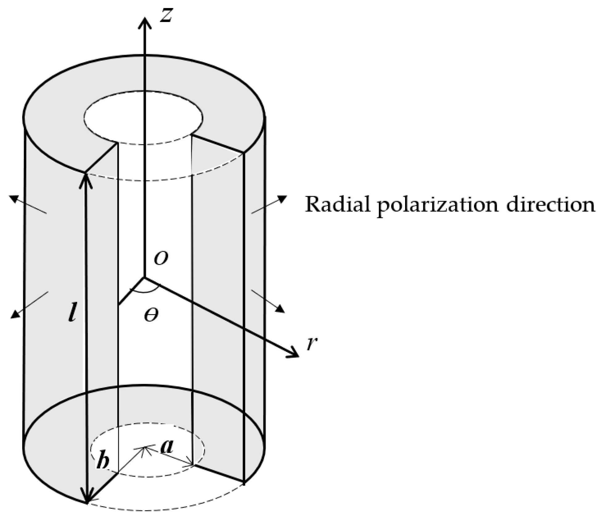
A piezoelectric cylindrical transducer polarized in the radial direction is shown in Figure 1. In the cylindrical coordinate system, a, b, and l represent the inner radius, the outer radius, and the length. The piezoelectric transducer is considered as mechanically unloaded. The polarization direction is along the plane radial direction and it is denoted by the four arrows. The external exciting electric field is parallel to the polarization direction.
The three-dimensional motion equations for the cylinder in coupled vibration are:
where r, θ, z are the cylindrical co-ordinates; , , are the three displacement components; and , , , , , are the stress components in the piezoelectric ceramic cylinder. The relationships between the strain and the displacement are as follows:
Here , , , , , are the strain components.
The constitutive piezoelectric equations for the radially polarized cylinder are as follows:
As the polarization direction is parallel to that of the electric field, the vibration is regarded as a coupled one of longitudinal and radial extensional vibrations, approximately; therefore, shearing and torsion stress and strain can be ignored. In this case, when the edge effect of the electric field is ignored, the following equations are obtained as:
where , , and , , are the electric field and electric displacement components [26].
Therefore, the linear constitutive piezoelectric equations for the radially polarized cylinder are expressed as:
where , and (i, j = 1, 2, 3) denote elastic, piezoelectric, and dielectric material constants.
The strains are linked to the displacement and radius by gradient relations.
Radial and longitudinal motion equations are:
Based on the piezoelectric equations and motion equations, in order to connect the radial vibration with longitudinal vibration, the mechanical coupling coefficient c is defined as,
The introduction of the mechanical coupling coefficient divides the coupled vibration of the piezoelectric cylindrical transducer into a short ring radial vibration and a long tube longitudinal vibration. In the following analyses, equivalent radial vibration and longitudinal vibration are presented, respectively.
2.1. The Equivalent Radial Vibration of the Piezoelectric Cylindrical Transducer in Coupled Vibration
For the radial vibration of the piezoelectric cylindrical transducer, since there are no free moving electrical charges in the piezoelectric ceramic material, the radial electric displacement satisfies the electrostatic condition:
The solution to Equation (9) is:
where is dependent of radius r. Then the radial electric field is expressed as:
where , and are constants.
Substituting Equations (8) and (11) into Equation (5d), the radial electric displacement can be obtained:
From Equations (10) and (12), the constants in Equation (11) can be obtained,
Therefore, the stress expressions of Equation (5a,b) are presented as follows:
where , , , .
Substituting Equation (14a,b) into Equation (7a) yields the motion equation for radial vibration:
Here , and . is the equivalent radial wave number; ω is the angular frequency, and is the equivalent radial sound speed.
By means of the mathematical software of Mathematica 9.0 (Wolfram Research, Champagne, IL, USA), the solution to Equation (15) can be obtained as:
where and are Bessel functions of the first kind and the second kind, . and are constants determined by the boundary conditions. is a Lommel function, its expression is:
From Equation (16), the radial strain is obtained,
The radial stress can be expressed as:
where:
The unknown constants and in Equation (16) are determined from the following boundary conditions,
Therefore, and are obtained,
Based on the radial voltage and the radial current , the electric admittance of the radial vibration is obtained:
where:
2.2. The Equivalent Longitudinal Vibration of the Piezoelectric Cylindrical Transducer in Coupled Vibration
For the longitudinal vibration of the piezoelectric cylindrical transducer, based on Equations (8), (11), (5c) and (7b), the longitudinal displacement is obtained,
From Equation (23), the longitudinal strain is expressed as:
The longitudinal stress is expressed as:
where the unknown constants and are determined from the following boundary conditions,
The constants are obtained:
For the longitudinal vibration of the cylinder, under quasi-static condition , and the mechanical coupling coefficient is expressed as .
The electric displacement is:
Here, the radial electric field is considered as a constant.
Based on the longitudinal voltage and the current , the electric admittance of longitudinal vibration is:
It is found that Equations (22) and (29) are closely related with material parameters, geometrical dimensions, the mechanical coupling coefficient, and the frequency. When the material parameters and the geometrical dimension are given, and are the functions of the mechanical coupling coefficient and the frequency. When and both reach the maximum, resonance frequency equations are obtained. For the resonance frequency equations, there are two groups of solutions. One group is the radial resonance frequency and the corresponding mechanical coupling coefficient. The other group is the longitudinal resonance frequency and the corresponding mechanical coupling coefficient.
3. The Dependence of Resonance Frequency and Mechanical Coupling Coefficient on Aspect Ratio
To analyze the dependence of the resonance frequency and the mechanical coupling coefficient on the aspect ratio, Equations (22) and (29) are solved. Since they are complex transcendental functions, it is difficult to obtain the analytical solutions and Mathematica 9.0 (Wolfram Research, Champagne, IL, USA) software is used to calculate the equations.
For the piezoelectric cylindrical transducer, the inner radius a = 0.016 m and outer radius b = 0.02 m are fixed, and the length l is changed. The piezoelectric material used is an equivalent of PZT-4 (Kunshan Risun Electronic Co., Ltd. Kunshan, China) manufactured in China. The relevant standard parameters of PZT-4 are listed in Table 1 [28].
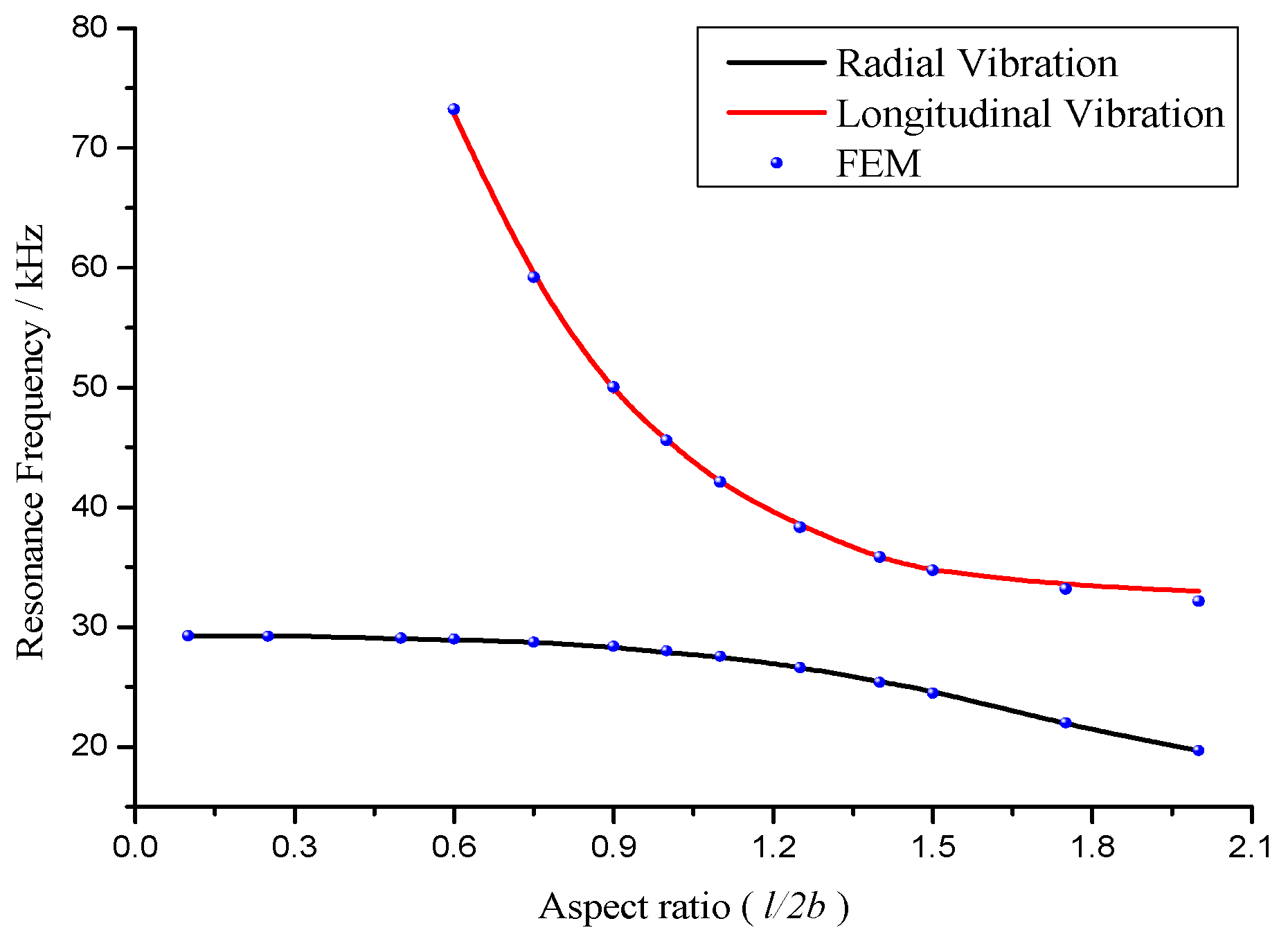
When the aspect ratio l/2b is increasing from 0.1, the resonance frequencies and the corresponding mechanical coupling coefficients are calculated and illustrated in Figure 2 and Figure 3.
Figure 2 demonstrates the dependence of the radial and longitudinal resonance frequencies on aspect ratio. It is seen that when the aspect ratio increases, the radial and longitudinal resonance frequencies decrease. The influence of longitudinal dimension on longitudinal resonance frequency is stronger than that on the radial resonance frequency. At the aspect ratio of 0.9 < l/2b < 1.5, the radial and longitudinal resonance frequencies are close. It is considered that there is a strong coupling between the radial and longitudinal partial systems.
In addition, the finite element method (FEM) is used to compute the radial and longitudinal resonance frequencies on different aspect ratios. The simulated resonance frequencies are illustrated in Figure 2. It is found that the theoretical results are in good agreement with the simulated results.
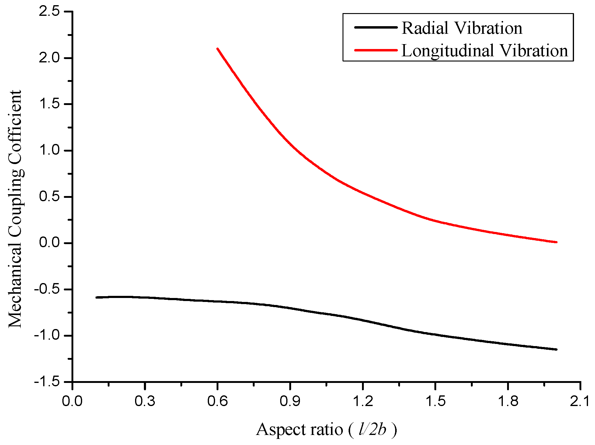
Figure 3 demonstrates the effect of aspect ratio on the corresponding radial and longitudinal mechanical coupling coefficients. From the resonance frequency equations, two kinds of mechanical coupling coefficients are found. The negative mechanical coupling coefficient corresponds to the radial vibration, and the positive to the longitudinal vibration. When the aspect ratio increases, the values of mechanical coupling coefficients decrease. At the aspect ratio of 0.9 < l/2b < 1.5, the mechanical coupling coefficients are at the vicinity of 1. The coupling of radial and longitudinal vibration is strong. At the aspect ratio of l/2b < 0.9 and l/2b > 1.5, the coupled vibration is considered weak.
It is concluded that when the radial and longitudinal resonance frequencies are far away from each other, the coupled vibration is weak. When the radial and longitudinal resonance frequencies are close, the coupled vibration is strong and the mechanical coupling coefficient is at the vicinity of 1.
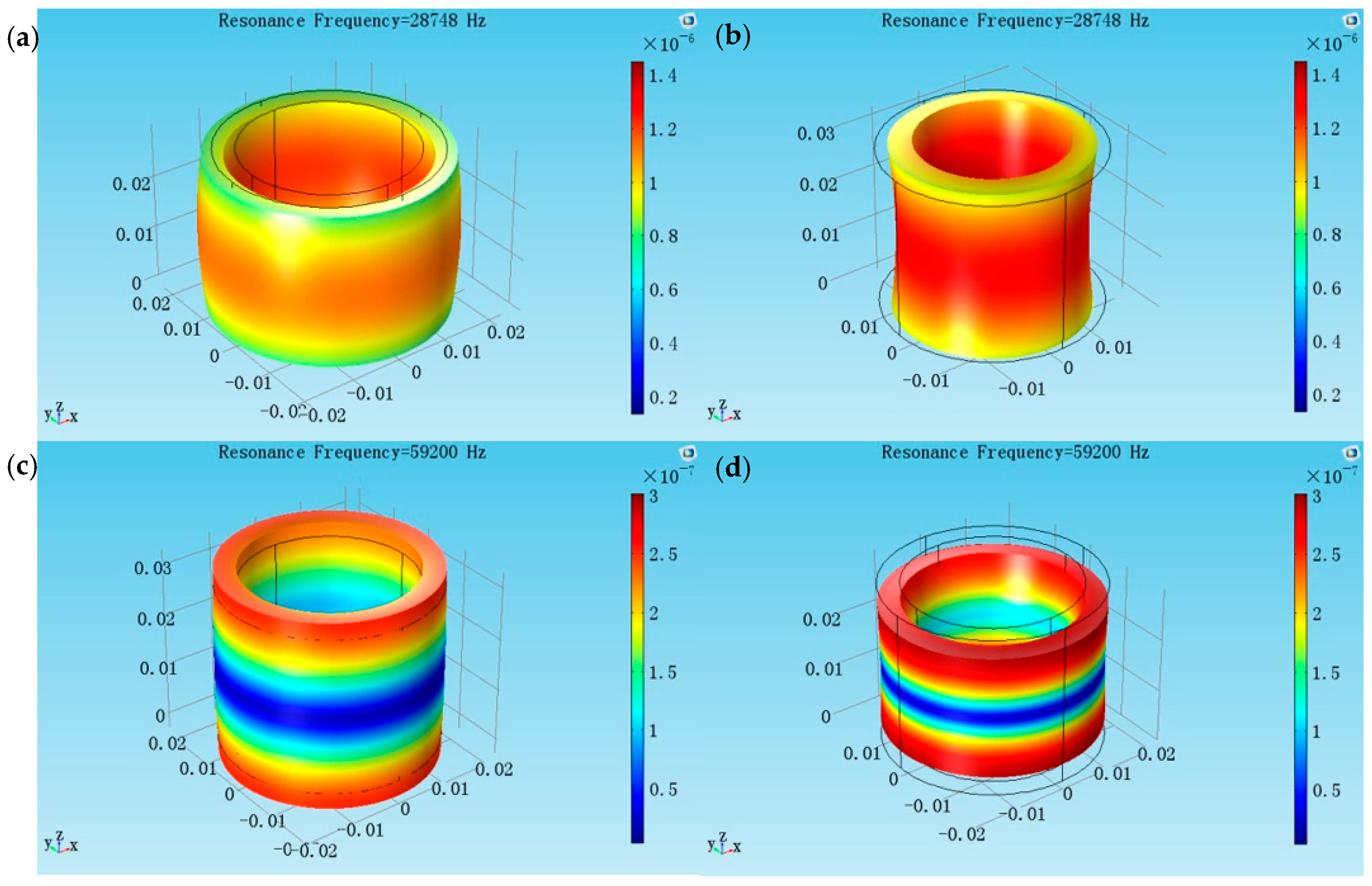
In addition, COMSOL Multiphysics 5.2 (COMSOL Inc. Stockholm, Sweden) is used to simulate the different coupled vibrational modes on different aspect ratios. The piezoelectric devices in the structural mechanics and the eigenfrequency type of analysis are selected, respectively. A radially polarized piezoelectric cylinder is structured and the material of the model is the lead zirconate titanate (PZT-4). The mesh density is set as 20. The elastic boundary condition is set as ‘free’. The low voltage is applied on the inside surface and outside surface is grounded.
Two radially polarized piezoelectric cylindrical transducer models are created separately, the inner and outer radii are the same (a = 0.016 m, b = 0.02 m), but the lengths are different (l = 0.03 m and l = 0.056 m). Figure 4 shows at the aspect ratio l/2b = 0.75, the radial resonance frequency is 28.748 kHz, and the longitudinal resonance frequency is 59.200 kHz. From the vibrational modes, the coupling between the radial and longitudinal vibration is weak. Figure 5 shows at the aspect ratio l/2b = 1.4, the radial resonance frequency is 25.400 kHz and the longitudinal resonance frequency is 35.854 kHz. From the vibrational modes, the radial vibration and longitudinal vibrations affect each other strongly. It is seen that the aspect ratio affects the coupled degree of the cylindrical transducer.
4. Experiments
To verify the theoretical analyses of coupled vibration, a radially polarized piezoelectric cylindrical transducer made of PZT-4, with the inner radius a = 0.016 m, the outer radius b = 0.02 m, and the length l = 0.03 m was manufactured. The resonance frequencies of the cylindrical transducer are measured by the Polytec-400 scanning vibrometer (Polytec, Waldbronn, Germany). The measured results are listed in Table 2.
In Table 2, the experiment method, the mechanical coupling coefficient method, and the finite element method are used, and the radial and longitudinal resonance frequencies are presented. The theoretical results are calculated by Mathematica 9.0 (Wolfram Research, Champagne, IL, USA) according to Equations (22) and (29). The results from the finite element method are calculated with COMSOL Multiphysics 5.2 (COMSOL Inc., Stockholm, Sweden), as the previous section presented.
It is seen that the mechanical coupling coefficient method results are in good agreement with the experimental results and the finite element method results.
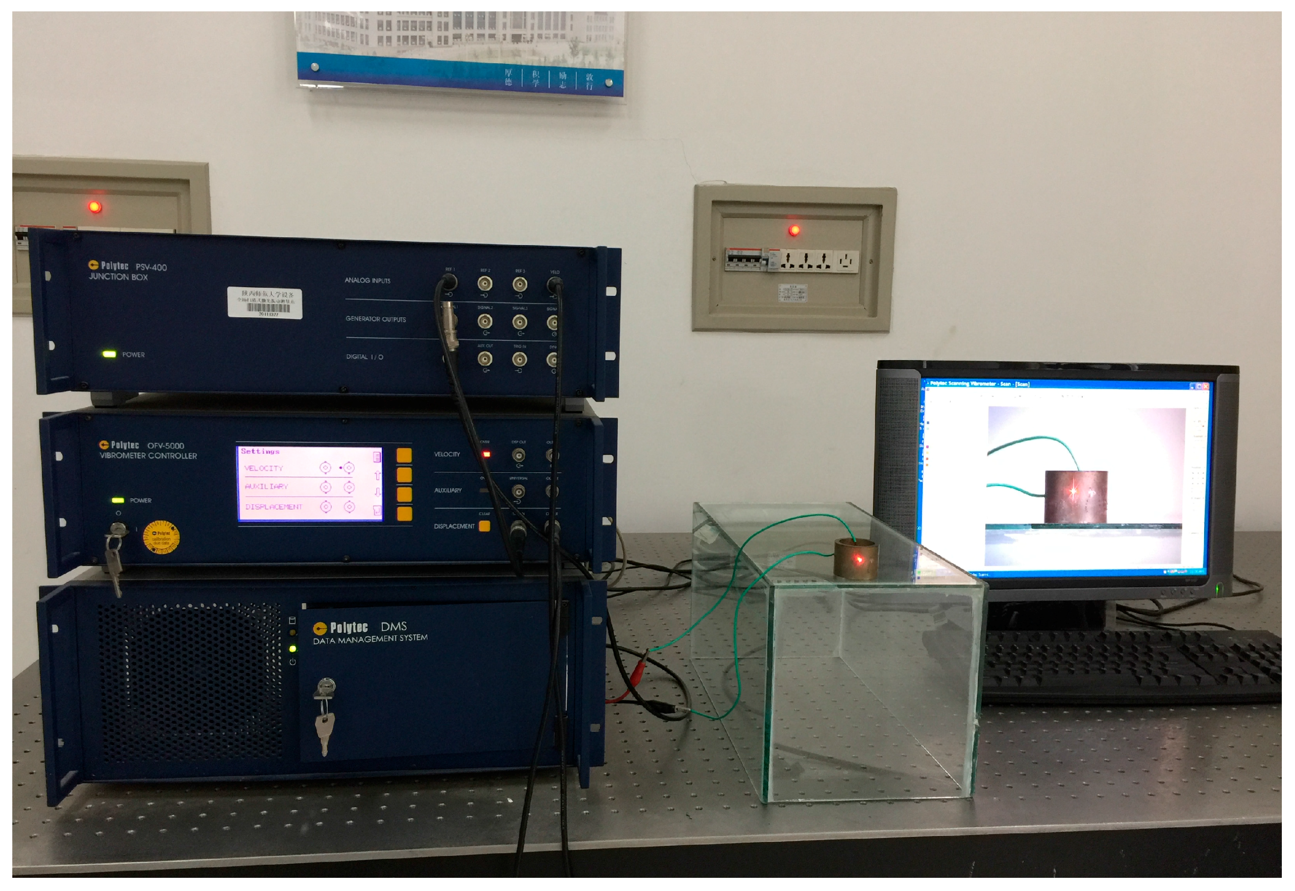
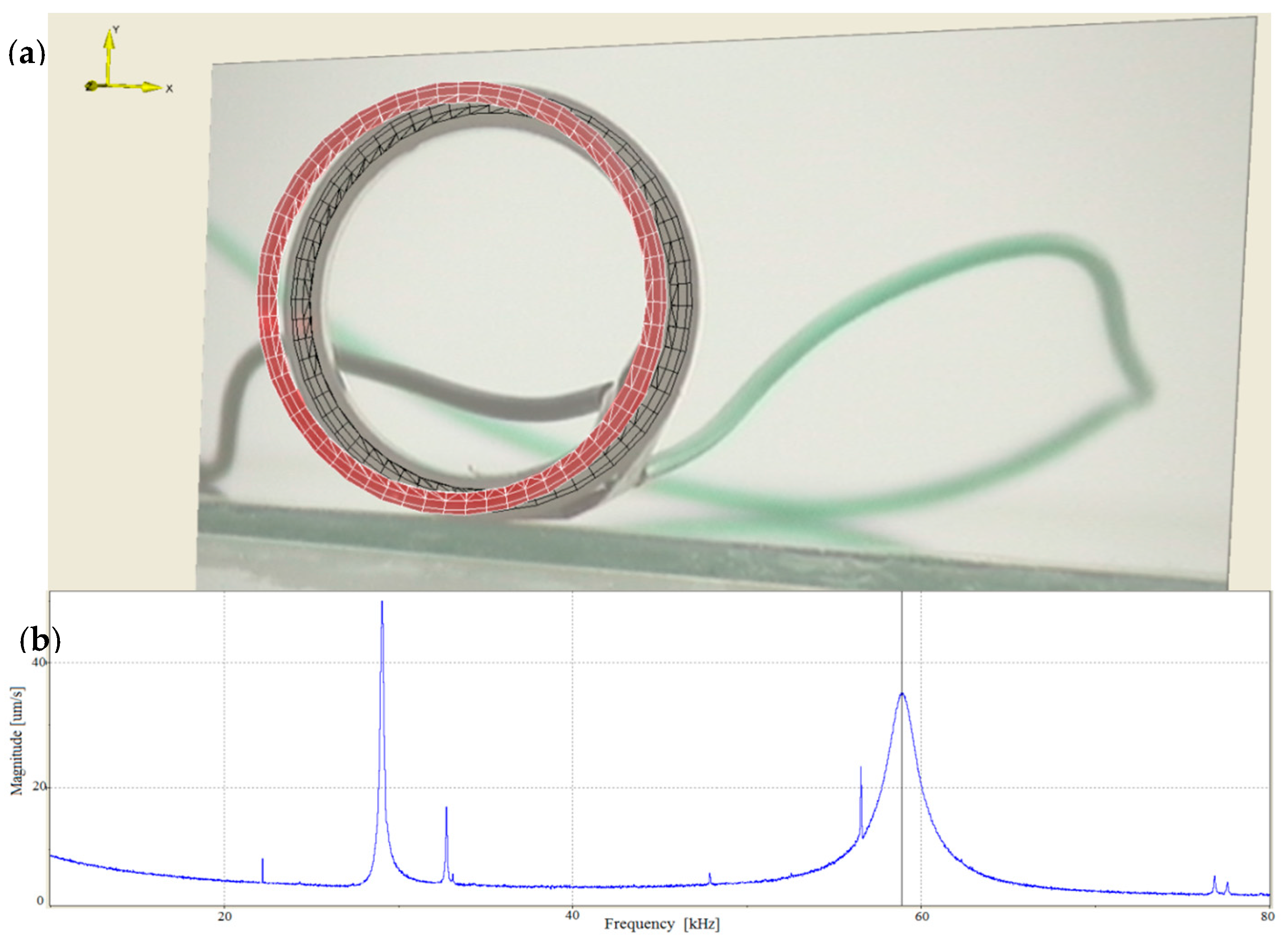
In addition, to present the surface vibrational distributions of the piezoelectric cylindrical transducer in coupled vibrations, Polytec scanning vibrometer (Polytec, Waldbronn, Germany) is used. In the measurement, a frequency-sweeping electric signal produced by Polytec OFV-5000 vibrometer controller is applied to the inside and outside surfaces of the piezoelectric cylinder. By means of the piezoelectric effect, mechanical vibration is produced and it excites the cylinder to vibrate. At the output end of the cylindrical transducer, Polytec PSV-400 laser scanning head automatically measures the vibration distribution on the surfaces. The experimental setup of the piezoelectric transducer is illustrated in Figure 6. The vibrational displacement distributions and frequency responses of the cylindrical transducer are recorded in Figure 7 and Figure 8, respectively. Figure 7a presents the radial vibrational distribution on the side surface of the transducer at the first resonance frequency. Figure 7b is the frequency-radial vibrational velocity curve. In the frequency response pattern, the frequency corresponding to the velocity peak is the radial resonance frequencies of the cylindrical transducer. Figure 8a illustrates the longitudinal vibrational distribution on the end surface of the cylindrical transducer at the longitudinal resonance frequency. Figure 8b is the frequency-longitudinal vibrational velocity curve. In the frequency response pattern, the frequency corresponding to the velocity peak is the longitudinal resonance frequency of the cylindrical transducer.
5. Conclusions
Coupled vibration of the radially polarized piezoelectric cylindrical transducer is analyzed based on the mechanical coupling coefficient method. The introduction of mechanical coupling coefficient divides the coupled vibration into the equivalent radial and longitudinal vibrations. By the theoretical derivation, the electric admittances as functions of mechanical coupling coefficients and resonance frequencies are obtained. The radial and longitudinal resonance frequency equations are acquired.
The dependence of resonance frequency and mechanical coupling coefficient on the aspect ratio of the transducer is analyzed. At the aspect ratio of 0.9 < l/2b < 1.5, the radial and longitudinal resonance frequencies are close, and the mechanical coupling coefficients are at the vicinity of ±1. It is considered that the coupling of the radial and longitudinal vibrations is strong. At the aspect ratio of l/2b < 0.9 and l/2b > 1.5, the radial and longitudinal resonance frequencies are far away each other, and the coupling of the two parts is weak.
In practical applications, the cylindrical piezoelectric transducer is neither a very thin ring nor a very long, slender cylinder. Therefore, its coupled vibration is significant and cannot be ignored. The analysis in this paper can be effectively used to analyze the coupled vibration. It is an approximately analytical method and can be used to other cases of coupled vibrations of piezoelectric devices which are nowadays widely used in ultrasonic emitters and sensors, such as underwater sound hydrophones, ultrasonic transducers, piezoelectric transformers, and other applications.
Acknowledgments
The authors wish to acknowledge the National Natural Science Foundation of China (11374200, 11674206) and the Fundamental Research Funds for the Central Universities (2016TS043) for their financial support.
Author Contributions
Jie Xu performed the theoretical derivation and numerical calculation. Shuyu Lin conceived and supervised the study. Yan Ma and Jie Xu carried out the experiments. Yifan Tang and Jie Xu conducted the simulation. Jie Xu and Shuyu Lin wrote the article. All authors contributed to the discussions.
Conflicts of Interest
The authors declare no conflict of interest.
Nomenclature
| Displacement component | |
| Stress component | |
| Strain component | |
| Electric field component | |
| Electric displacement component | |
| Elastic material constant | |
| Piezoelectric material constant | |
| Dielectric material constant | |
| Density | |
| Mechanical coupling coefficient | |
| Equivalent radial wave number | |
| Equivalent radial sound speed | |
| Bessel functions of the first kind | |
| Bessel functions of the second kind | |
| Lommel function |
References
- Ishiharaa, M.; Ootaoa, Y.; Kameo, Y. Electroelastic response of a piezoelectric cylinder with D∞ symmetry under axisymmetric mechanical loading. Mech. Res. Commun. 2016, 74, 1–7. [Google Scholar] [CrossRef]
- Hashemi, M.; Kargarnovin, M.H. Analysis of stress and electric fields in a piezoelectric long solid cylinder under axisymmetric thermo-electro-mechanical loadings. Math. Mech. Solids. 2016, 21, 578–594. [Google Scholar] [CrossRef]
- Kielczynski, P.; Szalewski, M. Compound piezoelectric cylindrical resonators as sensors of the rheological parameters of viscoelastic media. IEEE Trans. Ultrason. Ferroelectr. Freq. Control. 2007, 54, 1199–1206. [Google Scholar] [CrossRef] [PubMed]
- Lin, S.Y.; Fu, Z.Q.; Zhang, X.L.; Wang, Y.; Hu, J. Radially sandwiched cylindrical piezoelectric transducer. Smart Mater. Struct. 2013, 22, 015005. [Google Scholar] [CrossRef]
- Brown, D.A.; Aronov, B.; Bachand, C. Cylindrical transducer for producing an acoustic spiral wave for underwater navigation. J. Acoust. Soc. Am. 2012, 132, 3611–3613. [Google Scholar] [CrossRef] [PubMed]
- Wang, S.J. Study on the Radial Composite Piezoelectric Ceramic Transducer in Radial Vibration. Master’s Thesis, Shaanxi Normal University, Xi’an, China, 2011. [Google Scholar]
- Lin, S.Y.; Wang, S.J.; Fu, Z.Q. Electro-mechanical equivalent circuit for the radial vibration of the radially poled piezoelectric ceramic long tubes with arbitrary wall thickness. Sens. Actuators A Phys. 2012, 180, 87–96. [Google Scholar] [CrossRef]
- Ebenezer, D.D.; Abraham, P. Piezoelectric thin shell theoretical model and eigenfunction analysis of radially polarized ceramic cylinders. J. Acoust. Soc. Am. 1999, 105, 154–163. [Google Scholar] [CrossRef]
- Ebenezer, D.D.; Abraham, P. Eigenfunction analysis of radially polarized piezoelectric cylindrical shells of finite length. J. Acoust. Soc. Am. 1997, 102, 1549–1558. [Google Scholar] [CrossRef]
- Larbi, W.; Deu, J.F. A 3-D state space solution for free-vibration analysis of a radially polarized laminated piezoelectric cylinder filled with fluid. J. Sound Vib. 2011, 330, 162–181. [Google Scholar] [CrossRef]
- Aronov, B.; Brown, D.A. Coupled vibrations in hollow cylindrical shells of arbitrary aspect ratio. J. Acoust. Soc. Am. 2014, 135, 2388–2395. [Google Scholar] [CrossRef]
- Pasquali, M.; Gaudenzi, P. A nonlinear piezoelectric shell model: Theoretical and numerical considerations. J. Intell. Mater. Syst. Struct. 2016, 27, 724–742. [Google Scholar] [CrossRef]
- Zhang, T.T.; Shi, Z.F.; Spencer, B.F., Jr. Vibration analysis of a functionally graded piezoelectric cylindrical actuator. Smart Mater. Struct. 2008, 17, 025018. [Google Scholar] [CrossRef]
- Lu, P.; Lee, K.H.; Lim, S.P. Dynamical analysis of a cylindrical piezoelectric transducer. J. Sound Vib. 2003, 259, 427–443. [Google Scholar] [CrossRef]
- Yang, Z.T.; Yang, J.S.; Hu, Y.T.; Wang, Q.M. Vibration characteristics of a circular cylindrical panel piezoelectric transducer. IEEE Trans. Ultrason. Ferroelectr. Freq. Control. 2008, 55, 2327–2335. [Google Scholar] [CrossRef] [PubMed]
- Wu, G.J.; Zhang, R.; Zhang, L.; Zhu, H.H.; Zhang, N. Resonance magnetoelectric effect in radially polarized long cylindrical composite structures. J. Appl. Phys. 2013, 113, 214105. [Google Scholar] [CrossRef]
- Giebe, E.; Blechschmidt, E. Experimental and theoretical studies of extensional vibrations of rods and tubes. Ann. Phys. 1933, 18, 417–485. [Google Scholar] [CrossRef]
- Aronov, B.S. Coupled vibration analysis of the thin-walled cylindrical piezoelectric ceramic transducers. J. Acoust. Soc. Am. 2009, 125, 803–818. [Google Scholar] [CrossRef] [PubMed]
- Aronov, B.S.; Bachand, C.L. Piezoelectric cylindrical discs and solid rods: Dependence of the resonance frequencies and effective coupled coefficients on aspect ratio. J. Acoust. Soc. Am. 2016, 140, 2162–2172. [Google Scholar] [CrossRef] [PubMed]
- Lin, S.Y. Coupled vibration analysis of piezoelectric ceramic disk resonators. J. Sound Vib. 1998, 218, 205–217. [Google Scholar] [CrossRef]
- Lin, S.Y. Analysis of the equivalent circuit of piezoelectric ceramic disk ceramic disk resonantors in coupled vibration. J. Sound Vib. 2000, 231, 277–290. [Google Scholar]
- Lin, S.Y. Study on the equivalent circuit and coupled vibration for the longitudinally polarized piezoelectric ceramic hollow cylinders. J. Sound Vib. 2004, 275, 859–875. [Google Scholar] [CrossRef]
- Liu, S.Q.; Lin, S.Y. The analysis of the electro-mechanical model of the cylindrical radial composite piezoelectric ceramic transducer. Sens. Actuators A Phys. 2009, 155, 175–180. [Google Scholar] [CrossRef]
- Lin, S.Y. Coupled vibration of isotropic metal hollow cylinders with large geometrical dimensions. J. Sound Vib. 2007, 305, 308–316. [Google Scholar] [CrossRef]
- Kim, M.J.; Kim, J.S.; Cao, W.W. Aspect ratio dependence of electromechanical coupled coefficient of piezoelectric resonators. Appl. Phys. Lett. 2005, 87, 132901. [Google Scholar] [CrossRef]
- Ikeda, T. Fundamentals of Piezoelectricity; Oxford University Press: New York, NY, USA, 1996. [Google Scholar]
- Gradshteyn, I.S.; Ryzhik, I.M. Table of Integrals, Series, and Products, 7th ed.; Academic Press: Cambridge, MA, USA, 2007. [Google Scholar]
- Bechmann, R. Elastic, Piezoelectric, and Dielectric Constants of Polarized Barium Titanate Ceramics and Some Applications of the Piezoelectric Equations. J. Acoust. Soc. Am. 1956, 28, 347–350. [Google Scholar] [CrossRef]
Figure 1.
A radially polarized piezoelectric cylindrical transducer.

Figure 2.
The relationships between resonance frequency and aspect ratio.

Figure 3.
The relationships between mechanical coupling coefficient and aspect ratio.

Figure 4.
The coupled vibration modes of the cylindrical transducer at aspect ratio of l/2b = 0.75. (a,b) The radial extensional vibration mode of the coupled vibration; (c,d) The longitudinal extensional vibration mode of the coupled vibration.
Figure 4.
The coupled vibration modes of the cylindrical transducer at aspect ratio of l/2b = 0.75. (a,b) The radial extensional vibration mode of the coupled vibration; (c,d) The longitudinal extensional vibration mode of the coupled vibration.

Figure 5.
The coupled vibration modes of the cylindrical transducer at aspect ratio of l/2b = 1.4. (a,b) The radial extensional vibration mode of the coupled vibration; (c,d) The longitudinal extensional vibration mode of the coupled vibration.
Figure 5.
The coupled vibration modes of the cylindrical transducer at aspect ratio of l/2b = 1.4. (a,b) The radial extensional vibration mode of the coupled vibration; (c,d) The longitudinal extensional vibration mode of the coupled vibration.
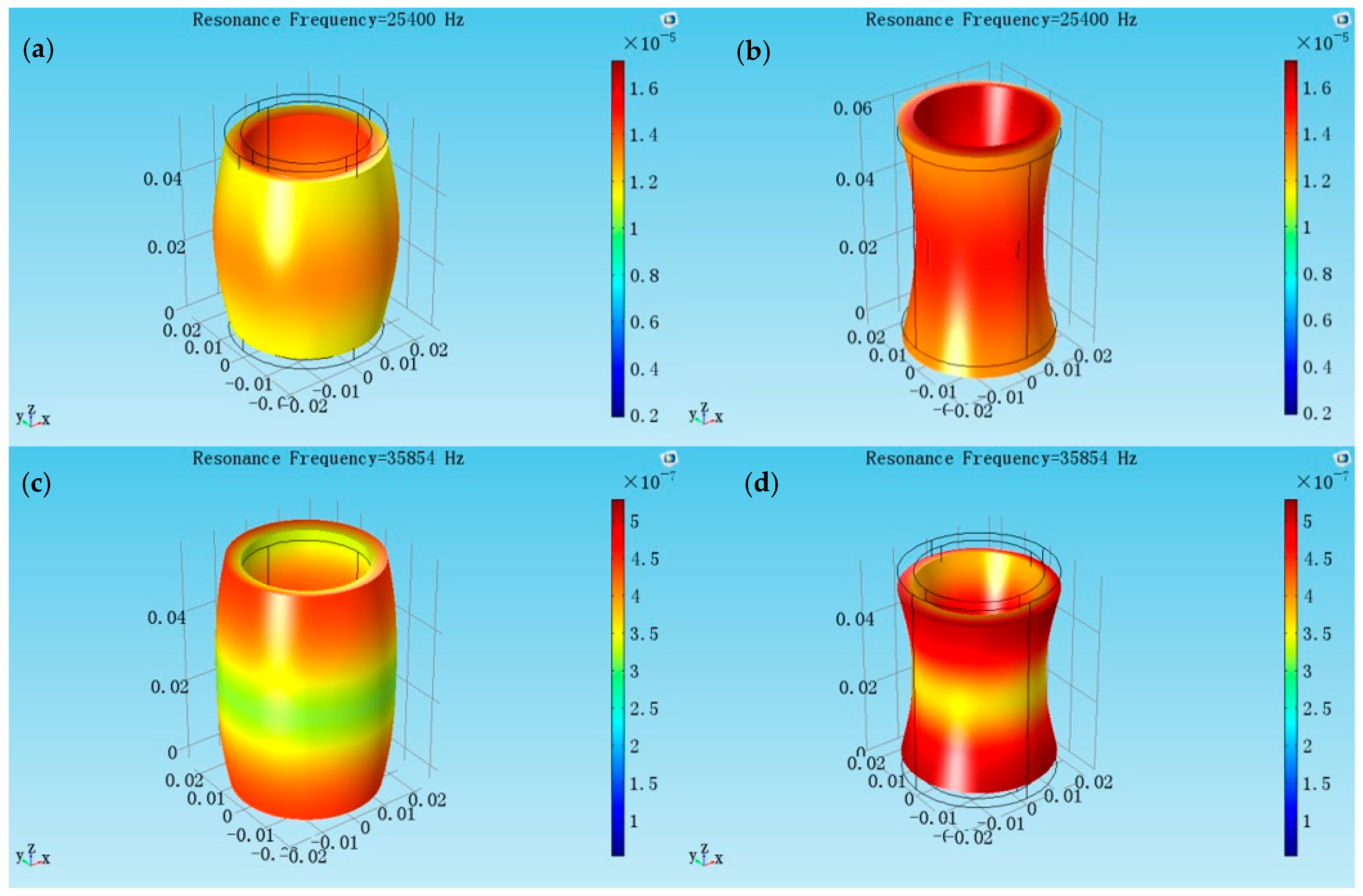
Figure 6.
Experimental setup for the measurement of the radially polarized piezoelectric cylindrical transducer.
Figure 6.
Experimental setup for the measurement of the radially polarized piezoelectric cylindrical transducer.

Figure 7.
(a) The radial vibrational distribution on the side surface of the cylindrical transducer at the radial resonance frequency; (b) The frequency-radial vibrational velocity curve.
Figure 7.
(a) The radial vibrational distribution on the side surface of the cylindrical transducer at the radial resonance frequency; (b) The frequency-radial vibrational velocity curve.
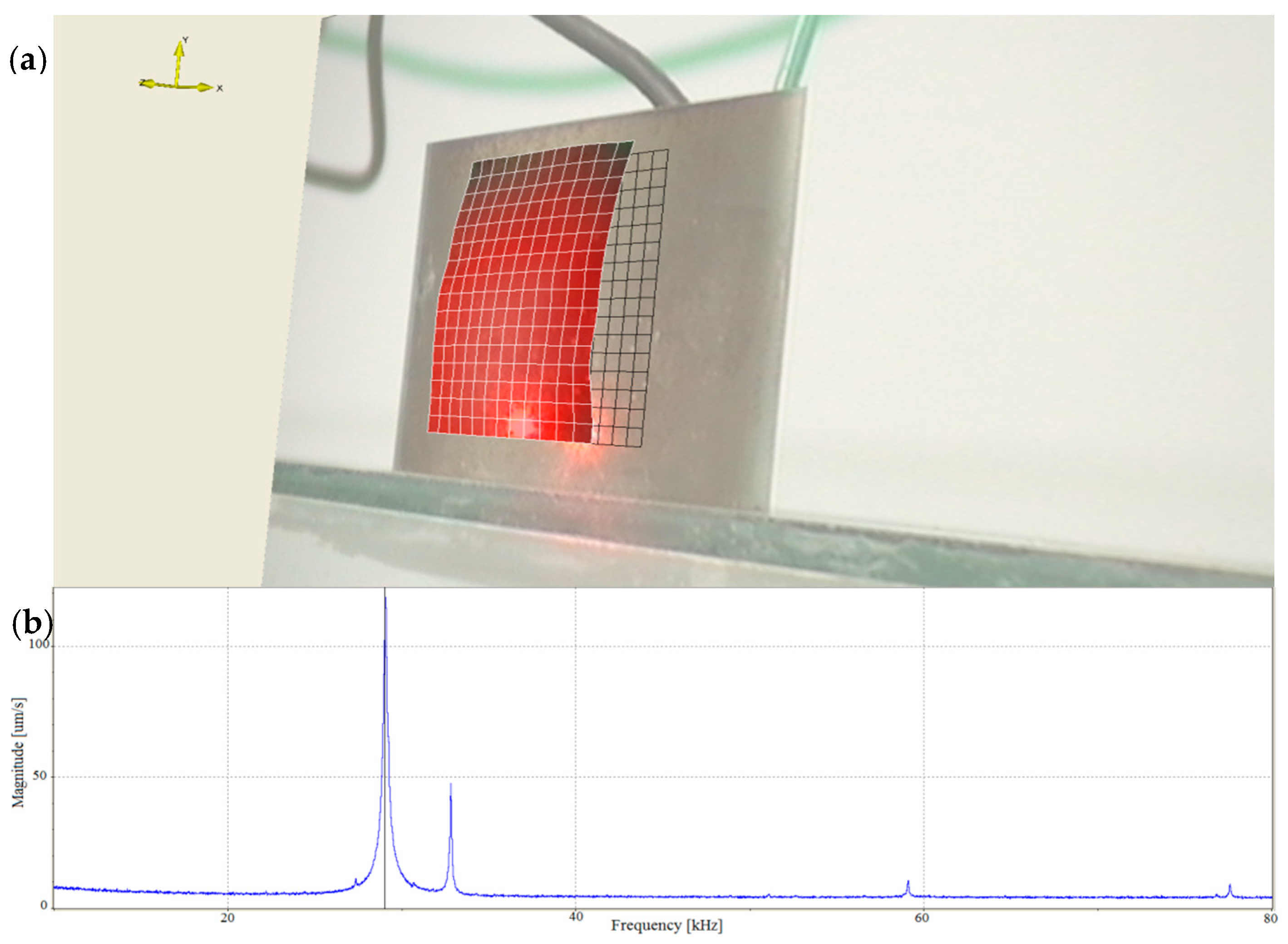
Figure 8.
(a) The longitudinal vibrational distribution on the end surface of the cylindrical transducer at the longitudinal resonance frequency; (b) The frequency-longitudinal vibrational velocity curve.
Figure 8.
(a) The longitudinal vibrational distribution on the end surface of the cylindrical transducer at the longitudinal resonance frequency; (b) The frequency-longitudinal vibrational velocity curve.


Table 1.
Standard parameters of PZT-4.
| Parameters | Value |
|---|---|
Table 2.
Comparison of resonance frequencies from different methods.
| Resonance Frequency (kHz) | ||
|---|---|---|
| Radial Vibration | Longitudinal Vibration | |
| Experiment measurement | 29.063 | 58.891 |
| Mechanical coupling coefficient method | 28.954 | 58.750 |
| Finite element method | 28.748 | 59.200 |
© 2017 by the authors. Licensee MDPI, Basel, Switzerland. This article is an open access article distributed under the terms and conditions of the Creative Commons Attribution (CC BY) license (http://creativecommons.org/licenses/by/4.0/).
Share and Cite
MDPI and ACS Style
Xu, J.; Lin, S.; Ma, Y.; Tang, Y. Analysis on Coupled Vibration of a Radially Polarized Piezoelectric Cylindrical Transducer. Sensors 2017, 17, 2850. https://doi.org/10.3390/s17122850
AMA Style
Xu J, Lin S, Ma Y, Tang Y. Analysis on Coupled Vibration of a Radially Polarized Piezoelectric Cylindrical Transducer. Sensors. 2017; 17(12):2850. https://doi.org/10.3390/s17122850
Chicago/Turabian StyleXu, Jie, Shuyu Lin, Yan Ma, and Yifan Tang. 2017. "Analysis on Coupled Vibration of a Radially Polarized Piezoelectric Cylindrical Transducer" Sensors 17, no. 12: 2850. https://doi.org/10.3390/s17122850
Note that from the first issue of 2016, this journal uses article numbers instead of page numbers. See further details here.