
D-Shaped Polarization Maintaining Fiber Sensor for Strain and Temperature Monitoring

Abstract
:1. Introduction
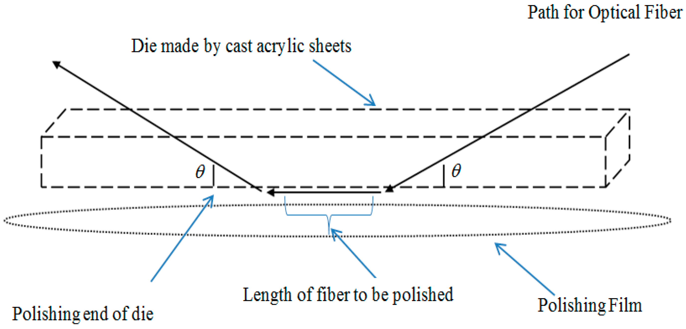
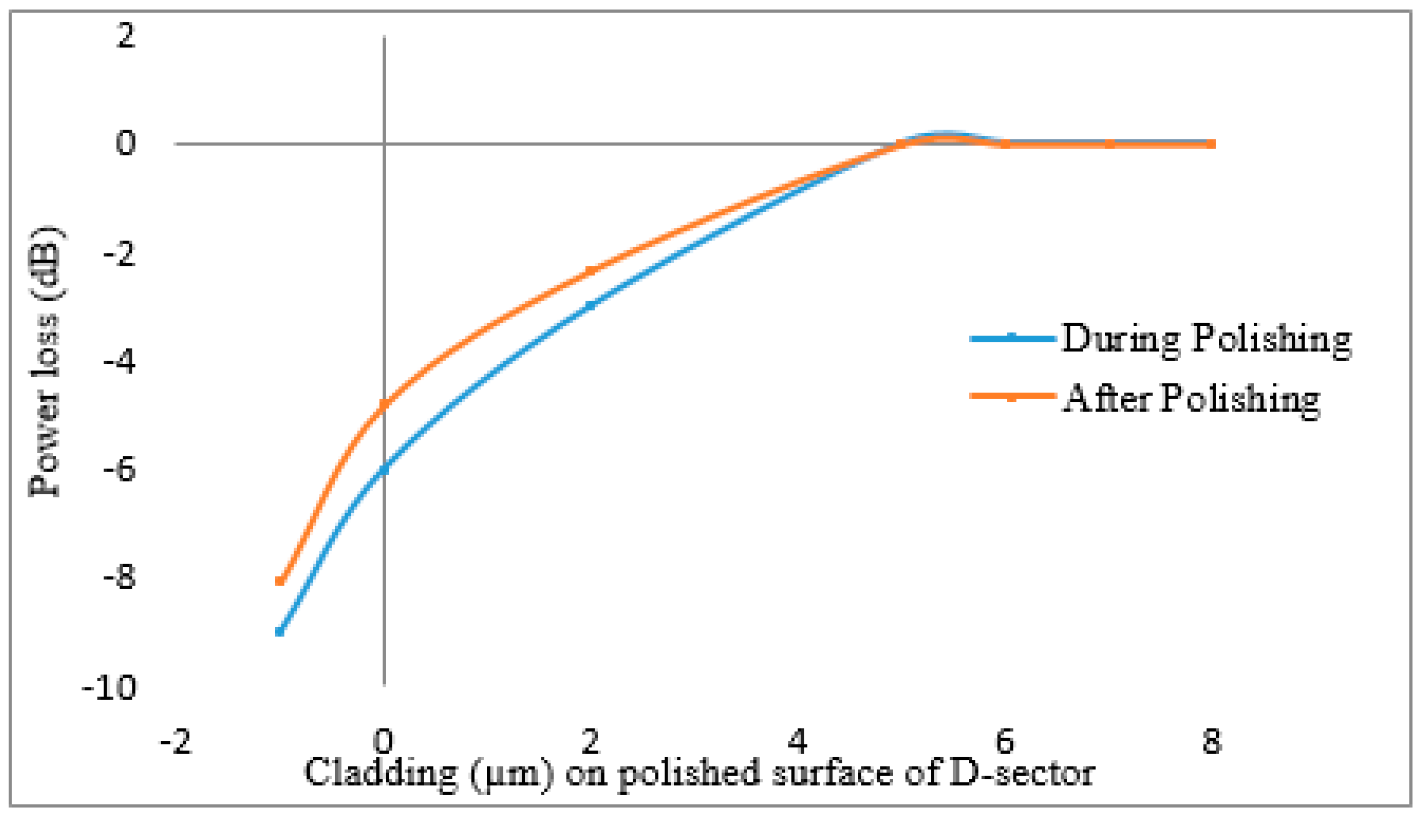
2. Fabrication Process
3. Experimental Setup and Sensing Principle
4. Results and Discussion
5. Comparison of this Sensor with Other FOS for Strain and/or Temperature
6. Conclusions
Acknowledgments
Author Contributions
Conflicts of Interest
References
- Harris, J.; Lu, P.; Larocque, H.; Xu, Y.; Chen, L.; Bao, X. Highly sensitive in-fiber interferometric refractometer with temperature and axial strain compensation. Opt. Express 2013, 21, 9996–10009. [Google Scholar] [CrossRef] [PubMed]
- Gouveia, C.; Chesini, G.; Cordeiro, C.M.; Baptista, J.; Jorge, P.A. Simultaneous measurement of refractive index and temperature using multimode interference inside a high birefringence fiber loop mirror. Sens. Actuators B Chem. 2013, 177, 717–723. [Google Scholar] [CrossRef]
- Kang, J.; Dong, X.; Zhu, Y.; Jin, S.; Zhuang, S. A fiber strain and vibration sensor based on high birefringence polarization maintaining fibers. Opt. Commun. 2014, 322, 105–108. [Google Scholar] [CrossRef]
- Zhang, Y.; Huang, J.; Lan, X.; Yuan, L.; Xiao, H. Simultaneous measurement of temperature and pressure with cascaded extrinsic Fabry-Perot interferometer and intrinsic Fabry-Perot interferometer sensors. Opt. Eng. 2014, 53, 067101. [Google Scholar] [CrossRef]
- Frazão, O.; Baptista, J.M.; Santos, J.L. Recent advances in high-birefringence fiber loop mirror sensors. Sensors 2007, 7, 2970–2983. [Google Scholar] [CrossRef]
- Froggatt, M.E.; Gifford, D.K.; Kreger, S.T.; Wolfe, M.S.; Soller, B.J. Distributed strain and temperature discrimination in unaltered polarization maintaining fiber. In Optical Fiber Sensors; Optical Society of America: Cancun, Mexico, 2006. [Google Scholar]
- Andre, R.M.; Marques, M.B.; Roy, P.; Frazao, O. Fiber loop mirror using a small core microstructured fiber for strain and temperature discrimination. IEEE Photon. Technol. Lett. 2010, 22, 1120–1122. [Google Scholar] [CrossRef]
- Naeem, K.; Kim, B.H.; Kim, B.; Chung, Y. Simultaneous multi-parameter measurement using Sagnac loop hybrid interferometer based on a highly birefringent photonic crystal fiber with two asymmetric cores. Opt. Express 2015, 23, 3589–3601. [Google Scholar] [CrossRef] [PubMed]
- Song, D.; Chai, Q.; Liu, Y.; Jiang, Y.; Zhang, J.; Sun, W.; Yuan, L.; Canning, J.; Peng, G.-D. A simultaneous strain and temperature sensing module based on FBG-in-SMS. Meas. Sci. Technol. 2014, 25, 55205–55210. [Google Scholar] [CrossRef]
- Wolfbeis, O.S. Fiber Optic Chemical Sensors and Biosensors; CRC Press: Boca Raton, FL, USA, 1991. [Google Scholar]
- Yin, S.S.; Ruffin, P. Fiber Optic Sensors; Wiley Online Library: Hoboken, NJ, USA, 2002. [Google Scholar]
- Qazi, H.H.; Mohammad, A.B.B.; Akram, M. Recent progress in optical chemical sensors. Sensors 2012, 12, 16522–16556. [Google Scholar] [CrossRef] [PubMed]
- Bilro, L.; Alberto, N.J.; Sá, L.M.; Pinto, J.D.L.; Nogueira, R. Analytical analysis of side-polished plastic optical fiber as curvature and refractive index sensor. J. Lightwave Technol. 2011, 29, 864–870. [Google Scholar] [CrossRef]
- Piliarik, M.; Homola, J.; Manı́ková, Z.; Čtyroký, J. Surface plasmon resonance sensor based on a single-mode polarization-maintaining optical fiber. Sens. Actuators B Chem. 2003, 90, 236–242. [Google Scholar] [CrossRef]
- Lu, H.; Tian, Z.; Yu, H.; Yang, B.; Jing, G.; Liao, G.; Zhang, J.; Yu, J.; Tang, J.; Luo, Y.; et al. Optical fiber with nanostructured cladding of TiO2 nanoparticles self-assembled onto a side polished fiber and its temperature sensing. Opt. Express 2014, 22, 32502–32508. [Google Scholar] [CrossRef] [PubMed]
- Slavı́k, R.; Homola, J.; Čtyroký, J.; Brynda, E. Novel spectral fiber optic sensor based on surface plasmon resonance. Sens. Actuators B Chem. 2001, 74, 106–111. [Google Scholar] [CrossRef]
- Han, Y.; Chen, Z.; Cao, D.; Yu, J.; Li, H.; He, X.; Zhang, J.; Luo, Y.; Lu, H.; Tang, J.; et al. Side-polished fiber as a sensor for the determination of nematic liquid crystal orientation. Sens. Actuators B Chem. 2014, 19, 663–669. [Google Scholar] [CrossRef]
- Tseng, S.-M.; Chen, C.-L. Side-polished fibers. Appl. Opt. 1992, 31, 3438–3447. [Google Scholar] [CrossRef] [PubMed]
- South, I. Novel D-type fiber optic localized plasmon resonance sensor realized by femtosecond laser engraving. J. Laser Micro/Nanoeng. 2010, 5. [Google Scholar] [CrossRef]
- Chen, C.H.; Tsao, T.C.; Tang, J.L.; Wu, W.T. A multi-D-shaped optical fiber for refractive index sensing. Sensors 2010, 10, 4794–4804. [Google Scholar] [CrossRef] [PubMed]
- Chen, C.H.; Tang, J.L.; Wu, W. Novel Multi-D-Shape Fiber Optic Biosensor. In Proceedings of the 5th International Symposium on Machinery and Mechatronics for Agriculture and Biosystems Engineering, Fukuoka, Japan, 25–28 June 2010.
- Cheng, S.-F.; Chau, L.-K. Colloidal gold-modified optical fiber for chemical and biochemical sensing. Anal. Chem. 2003, 75, 16–21. [Google Scholar] [CrossRef] [PubMed]
- Chau, L.-K.; Lin, Y.-F.; Cheng, S.-F.; Lin, T.-J. Fiber-optic chemical and biochemical probes based on localized surface plasmon resonance. Sens. Actuators B Chem. 2006, 11, 100–105. [Google Scholar] [CrossRef]
- Zhong, C.; Shen, C.; You, Y.; Chu, J.; Zou, X.; Dong, X.; Jin, Y.; Wang, J. A polarization-maintaining fiber loop mirror based sensor for liquid refractive index absolute measurement. Sens. Actuators B Chem. 2012, 16, 360–364. [Google Scholar] [CrossRef]
- Feng, D. D-shaped plastic optical fiber sensor for testing refractive index. IEEE Sens. J. 2014, 14, 1673–1676. [Google Scholar]
- Jiang, L.; Zhao, L.; Wang, S.; Yang, J.; Xiao, H. Femtosecond laser fabricated all-optical fiber sensors with ultrahigh refractive index sensitivity: Modeling and experiment. Opt. Express 2011, 19, 17591–17598. [Google Scholar] [CrossRef] [PubMed]
- Zhao, J.; Yin, G.; Liao, C.; Liu, S.; He, J.; Sun, B.; Wang, G.; Xu, X.; Wang, Y. Rough side-polished fiber with surface scratches for sensing applications. IEEE Photon. J. 2015, 73, 1–7. [Google Scholar] [CrossRef]
- Kaminow, I.P. Polarization-maintaining fibers. Appl. Sci. Res. 1984, 41, 257–270. [Google Scholar] [CrossRef]
- Grattan, K.T.V.; Meggitt, B.T. Optical Fiber Sensor Technology: Fundamentals; Springer: Heidelberg, Germany, 2000. [Google Scholar]
- Shen, C.; Zhong, C.; Chu, J.; Zou, X.; Jin, Y.; Wang, J.; Dong, X.; Li, Y.; Wang, L. Temperature-insensitive strain sensor using a fiber loop mirror based on low-birefringence polarization-maintaining fibers. Opt. Commun. 2013, 28, 31–34. [Google Scholar] [CrossRef]
- Frazão, O.; Marques, B.V.; Jorge, P.; Baptista, J.M.; Santos, J.L. High birefringence D-type fibre loop mirror used as refractometer. Sens. Actuators B Chem. 2008, 13, 108–111. [Google Scholar] [CrossRef]
- Tan, Y.-N.; Zhang, Y.; Jin, L.; Guan, B.-O. Strain and temperature discrimination using concatenated fiber grating lasers. In Asia Pacific Optical Sensors Conference; International Society for Optics and Photonics: Bellingham, WA, USA, 2012. [Google Scholar]
- Jiang, N.; Zhu, H.; Bao, K.; Hu, Y. Simultaneous discrimination of strain and temperature using dual-gratings in one fiber. Optik Int. J. Light Electron Opt. 2015, 126, 3974–3977. [Google Scholar] [CrossRef]
- Wang, L.; Zhang, W.; Wang, B.; Chen, L.; Bai, Z.; Gao, S.; Li, J.; Liu, Y.; Zhang, L.; Zhou, Q. Simultaneous strain and temperature measurement by cascading few-mode fiber and single-mode fiber long-period fiber gratings. Appl. Opt. 2014, 53, 7045–7049. [Google Scholar] [CrossRef] [PubMed]
- Li, C.; Ning, T.; Wen, X.; Li, J.; Zheng, J.; You, H.; Chen, H.; Zhang, C.; Jian, W. Strain and temperature discrimination using a fiber Bragg grating and multimode interference effects. Opt. Commun. 2015, 343, 6–9. [Google Scholar] [CrossRef]
- Gonzalez-Reyna, M.A.; Alvarado-Mendez, E.; Estudillo-Ayala, J.M.; Vargas-Rodriguez, E.; Sosa-Morales, M.E.; Sierra-Hernandez, J.M.; Jauregui-Vazquez, D.; Rojas-Laguna, R. Laser temperature sensor based on a fiber Bragg grating. IEEE Photonics Technol. Lett. 2015, 27, 1141–1144. [Google Scholar] [CrossRef]
- Liu, H.B.; Liu, H.Y.; Peng, G.D.; Chu, P.L. Strain and temperature sensor using a combination of polymer and silica fibre Bragg gratings. Opt. Commun. 2003, 219, 139–142. [Google Scholar] [CrossRef]
- Chen, H.F.; Wang, D.N.; Wang, Y. Simultaneous strain and temperature sensing using a slightly tapered optical fiber with an inner cavity. Analyst 2015, 140, 1859–1862. [Google Scholar] [CrossRef] [PubMed]
- Han, Y.-G. Temperature-insensitive strain measurement using a birefringent interferometer based on a polarization-maintaining photonic crystal fiber. Appl. Phys. B 2009, 95, 383–387. [Google Scholar] [CrossRef]
- Noh, T.-K.; Lee, Y.-W. Study on Dependence of Polarization-Maintaining Photonic Crystal Fiber-Based Polarimetric Strain Sensor on Sensing Fiber Length. J. Korean Inst. Illum. Electr. Install. Eng. 2013, 27, 1–6. [Google Scholar] [CrossRef]


| No. | Type of Fiber | Polishing Technique | Dimension (h × w × l) *1 | Application | Ref. |
|---|---|---|---|---|---|
| 1 | Multimode optical fiber | Femtosecond laser micromachining | 100 µm × 250 µm × 1 mm | Liquid refractive index measurements | [20] |
| 2 | Polarization-maintaining fiber | Hydrofluoric acid etching | - | Liquid refractive index measurements | [24] |
| 3 | Plastic Optical Fiber | Rotating grinding wheel | 10 mm (length) | Liquid refractive index measurements | [25] |
| 4 | Single-mode optical fiber | Femtosecond laser micromachining | 60 μm × 75 μm (h × l) | Liquid refractive index measurements | [26] |
| 5 | Multimode optical fiber | Femtosecond laser micromachining | 100 µm × 1 mm (h × l) | Liquid refractive index measurements | [21] |
| 6 | Single-mode optical fiber | Mechanical wheel lapping | 4 mm (length) | Strain and Temperature | [27] |
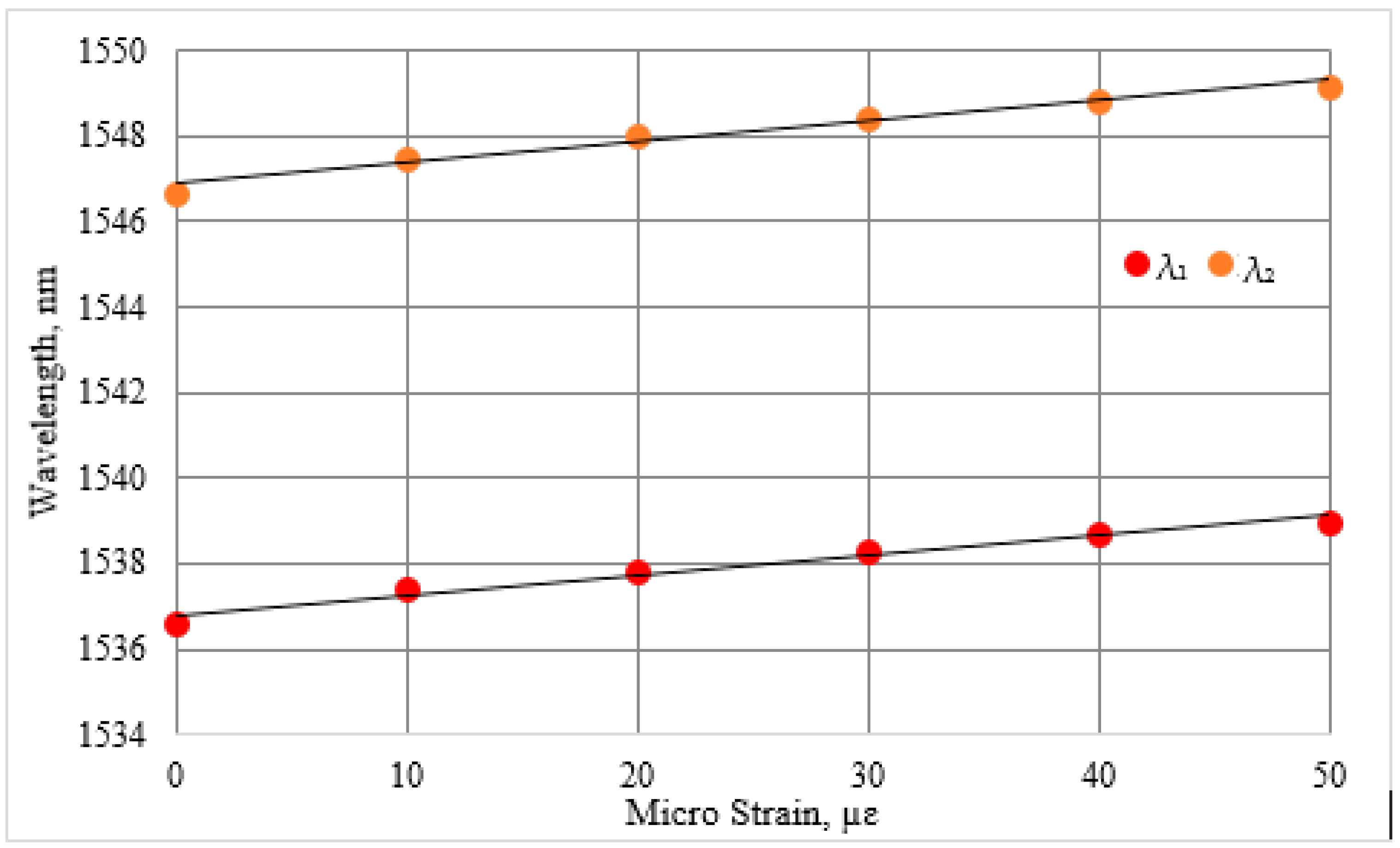
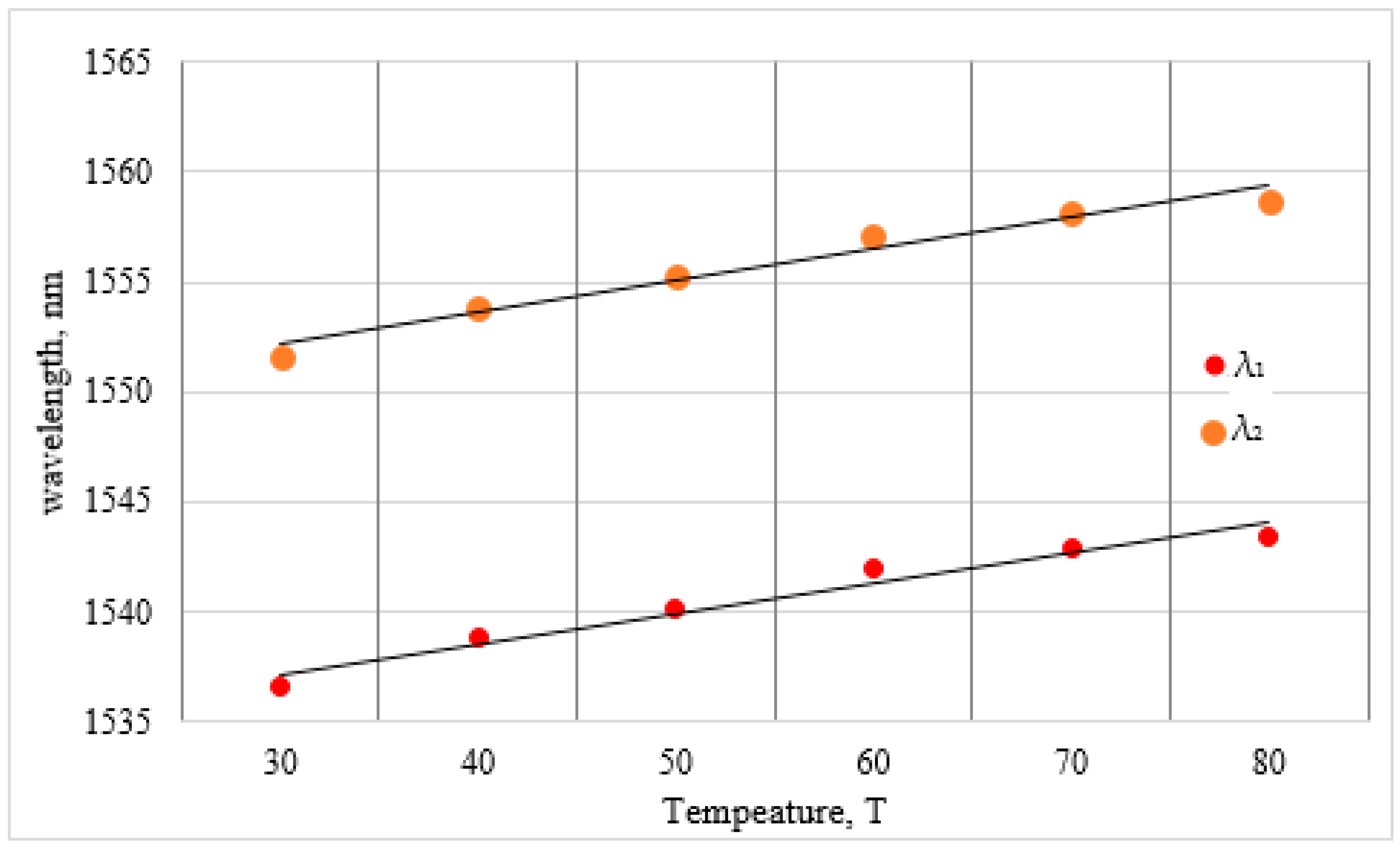
| Kε (nm/µε) | KT (nm/°C) | |
|---|---|---|
| First Minima (λ1) | 0.046 | 0.13 |
| Second Minima (λ2) | 0.047 | 0.14 |
| No | Sensing Principle/Type of Fiber | Sensing Application | Sensitivity | Ref. | |
|---|---|---|---|---|---|
| Strain pm/με | Temperature pm/°C | ||||
| 1 | Hybrid optical fiber structure FLM-long period fiber gratings (LPFGs)-few mode fiber (FMF) | Strain and Temperature | −2.9 | −17.6 | [34] |
| 2 | FLM-low-birefringence PMF | Strain | 3.5 | - | [30] |
| 3 | No-core fiber (NCF)-fiber Bragg grating (FBG)-SMF | Strain and Temperature | 1.19 | 12.8 | [35] |
| 4 | Erbium-doped fiber (EDF)-FBG-Mach–Zehnder interferometer (MZI) | Temperature | - | 18.8 | [36] |
| 5 | Combined polymer and silica-based FBG | Strain and Temperature | 1.48 | - | [37] |
| 6 | Slightly tapered optical fiber with an inner air cavity | Strain and Temperature | −16.12 | 85.95 | [38] |
| 7 | Dual gratings in one fiber | Strain and Temperature | 2.57 | 8.5 | [33] |
| 8 | PM-photonic crystal fiber (PM-PCF) | Strain | 1.3 | 0.3 | [39] |
| 9 | PM-PCF | Strain | 2.04 | - | [40] |
| 10 | PM-FLM | Strain and vibration | 1.09 | - | [3] |
| 11 | D-shaped PM-FLM | Strain and Temperature | 46 | 130 | This work |
© 2016 by the authors; licensee MDPI, Basel, Switzerland. This article is an open access article distributed under the terms and conditions of the Creative Commons Attribution (CC-BY) license (http://creativecommons.org/licenses/by/4.0/).
Share and Cite
Qazi, H.H.; Mohammad, A.B.; Ahmad, H.; Zulkifli, M.Z. D-Shaped Polarization Maintaining Fiber Sensor for Strain and Temperature Monitoring. Sensors 2016, 16, 1505. https://doi.org/10.3390/s16091505
Qazi HH, Mohammad AB, Ahmad H, Zulkifli MZ. D-Shaped Polarization Maintaining Fiber Sensor for Strain and Temperature Monitoring. Sensors. 2016; 16(9):1505. https://doi.org/10.3390/s16091505
Chicago/Turabian StyleQazi, Hummad Habib, Abu Bakar Mohammad, Harith Ahmad, and Mohd Zamani Zulkifli. 2016. "D-Shaped Polarization Maintaining Fiber Sensor for Strain and Temperature Monitoring" Sensors 16, no. 9: 1505. https://doi.org/10.3390/s16091505