Article

Comparative Study of Two Different TiO2 Film Sensors on Response to H2 under UV Light and Room Temperature

1
State Key Laboratory of Photocatalysis on Energy and Environment, Research Institute of Photocatalysis, Fuzhou University, Fuzhou 350002, China
2
College of Chemistry, Fuzhou University, Fuzhou 350108, China
*
Author to whom correspondence should be addressed.
Sensors 2016, 16(8), 1249; https://doi.org/10.3390/s16081249
Submission received: 27 June 2016 / Revised: 25 July 2016 / Accepted: 2 August 2016 / Published: 8 August 2016
(This article belongs to the Section Chemical Sensors)

Abstract

:
An anatase TiO2 film sensor was prepared by a facile in-situ method on the interdigitated Au electrode deposited on the alumina substrate. The structure, morphology and the optical properties of the in-situ TiO2 film sensor were characterized by X-ray diffraction, Scanning Electron Microscopy, and UV-vis diffuse reflectance spectra. The photo-assisted gas sensitivities of the prepared film towards H2 gas were evaluated at room temperature in N2 and synthetic air atmospheres. As compared to TiO2 film sensor prepared by drop-coating method, this in-situ TiO2 film sensor exhibited a more compact structure composed of uniform TiO2 microspheres as well as a better gas sensitivity towards H2 under UV irradiation, especially in synthetic air. The photo-electrochemical measurements suggest that these improvements may be associated with the efficient charge transfer in the TiO2 interface induced by the TiO2 microsphere structure. This study might offer a feasible approach to develop photo-assisted gas sensors at ambient temperature.

Graphical Abstract

1. Introduction

In the recent years, gas sensors have been widely investigated due to the increasing demand for their practical applications notably in the detection of dangerous/poisonous gases, medical practice, security, industrial manufacture, and bioengineering [1,2,3,4,5,6]. Metal oxide gas sensors play important roles in the gas sensing research because of their prominent advantages of high sensitivity, good stability, and fast response. In particular, TiO2 metal oxides were found very promising in numerous application areas including photovoltaics, photocatalysis, catalysis, and sensors [7,8,9,10,11]. When TiO2 oxides are utilized as thermal sensors, they might be limited by the high operating temperatures, issues not well accepted from the perspectives of energy cost and the environmental safety. Furthermore, their repeatability and stability could decrease after exposure to reducing or oxidizing gases [12,13,14]. With this respect, a number of studies show that doping the metal as well as controlling its morphology could improve the sensitivities of the metal oxides gas sensors at low temperatures [15,16,17,18,19,20,21,22,23,24]. For instance, Pb-doped TiO2 nanofibers investigated by Moon et al. [15] yielded highly sensitive NO2 sensors with remarkably stable responses to NO2 gas towards concentrations reaching as low as 0.16 ppm at 180 °C. Some studies showed that doping TiO2 with metal ions such as Ta, La, Nb, and Cr is feasible and results in improved O2 sensitivities [16,17,18,19,20]. In addition, Noble metals like Pt, Pd, Au, and Ag have been utilized to reduce the operation temperatures through effective improvements of the interaction between TiO2 surface and the gas molecules [21,22,23,24]. Other studies addressed some limitations of the gas sensors by improving the structure and morphology of the gas sensor films. For example, a cauliflower-like structure of λ-Al2O3 films was achieved by chemical vapor deposition and showed an improved response to CO2 gas [25]. Sonker et al. [26] successfully prepared a nano-petal like NO2 sensor through a cheap and easy chemical route. Plecenik et al. [21] constructed a highly-sensitive room-temperature semiconductor gas sensor based on nanoscale Pt-TiO2-Pt sandwich.
On the other hand, considerable efforts have recently been devoted to enhancing the gas sensitivity of the semiconductor sensors and decrease their response temperatures by the use of light radiation [27,28], including metal oxides [29,30,31,32]. With the introduction of light (exciting the response of semiconductor), the gas sensing operating temperature could be reduced to a great extent, and was even applicable at room temperature. For example, we have also previously reported a ZnO gas sensor for acetone and ethylene under visible light irradiation at room temperature [31]. Moreover, the photo-assisted response properties could be improved by means of metal doping, control of the structure morphology, coupled with a facile preparation process.
A number of researchers attempted various methods to simplify the preparation process of the gas sensors. For example, Su et al. [33] prepared Pt-PPy thin film by layer-by-layer (LBL) self-assembly method for H2 gas sensing. Other methods are utilized as well to enhance gas response including ultrasonic spray pyrolysis [4], screen printing [18,19,22], RF magnetron sputtering [27], electro-spinning [22], chemical vapor deposition [25], electrothermal [29], co-sputtering [17], and matrix assisted pulsed laser evaporation [34]. Drop-coating is also a common method utilized to prepare gas sensors using powder materials [1,2,13,31,32,33,35,36]. Even though these strategies were successful in addressing particular issues, most of them suffer from either high operating temperatures or complex manufacturing processes.
As for sensors for H2 detection, several studies have also been reported including methods based on catalytic, thermal conductivity, electrochemical, resistance, work function, mechanical, and optical and acoustic [37,38,39]. In recent years, solid electrolytes with proton conductivity [40] have attracted increasing attention of electrochemical devices developers. These materials can be implemented in different medium- and high-temperature electrochemical devices, including fuel cells, electrolysis cells for hydrogen production and hydrogen sensors [41,42]. Additionally, Pd nanogap-based sensors on flexible substrates were reported to have some advantages for electrical H2 detection, such as a high sensitivity and selectivity to H2 at room temperature [43,44]. Metal oxide gas sensors have been widely used for hydrogen gas sensor applications because of their high sensitivity, fast response, long lifespan and feasibility to be miniaturized for use in the microelectronic devices [45,46]. Moreover, the morphologies and structures of metal oxides may play important roles in the sensor characteristics [47,48,49,50,51]. For example, a pure and doped WO3 nanoparticle, forming nanoporous layers as testing material was used for improving chemical selectivity and sensitivity of semiconductor gas sensors consisting of nanostructured thin films [47]. Especially, TiO2 tubular structures prepared by anodization have shown significant hydrogen sensing properties [48,49]. Paulose et al. [50] reported remarkable hydrogen sensing properties of TiO2 nanotube arrays prepared by an anodization of Ti foil in an electrolyte containing fluorine ion. The dramatic change in resistance is believed to be due to the highly active surface states on the nanoscale walls of the tubes, high surface area of the nanotube architecture, and the well-ordered geometry allowing for hydrogen-sensitive tube-to-tube electrical connections. Moon et al. [51] also reported a highly sensitive hydrogen sensor consisting of Pd-decorated TiO2 tubular structures prepared by anodization with patterned electrodes on SiO2/Si substrate. These works showed that the hydrogen sensing properties of TiO2 sensors were somewhat determined by their nanostructures. However, little attention was paid to the photo-assisted sensing properties of TiO2 films with different nanostructures.
In this present work, we have compared the photo-assisted hydrogen sensing properties of two kinds of TiO2 films, one prepared by an in-situ method and the other a dip-coating method. Hydrogen sensing measurements were performed under N2 and synthetic air. The in-situ TiO2 film sensor showed a better hydrogen sensing property than the dip-coating TiO2 film sensor.

2. Experiments

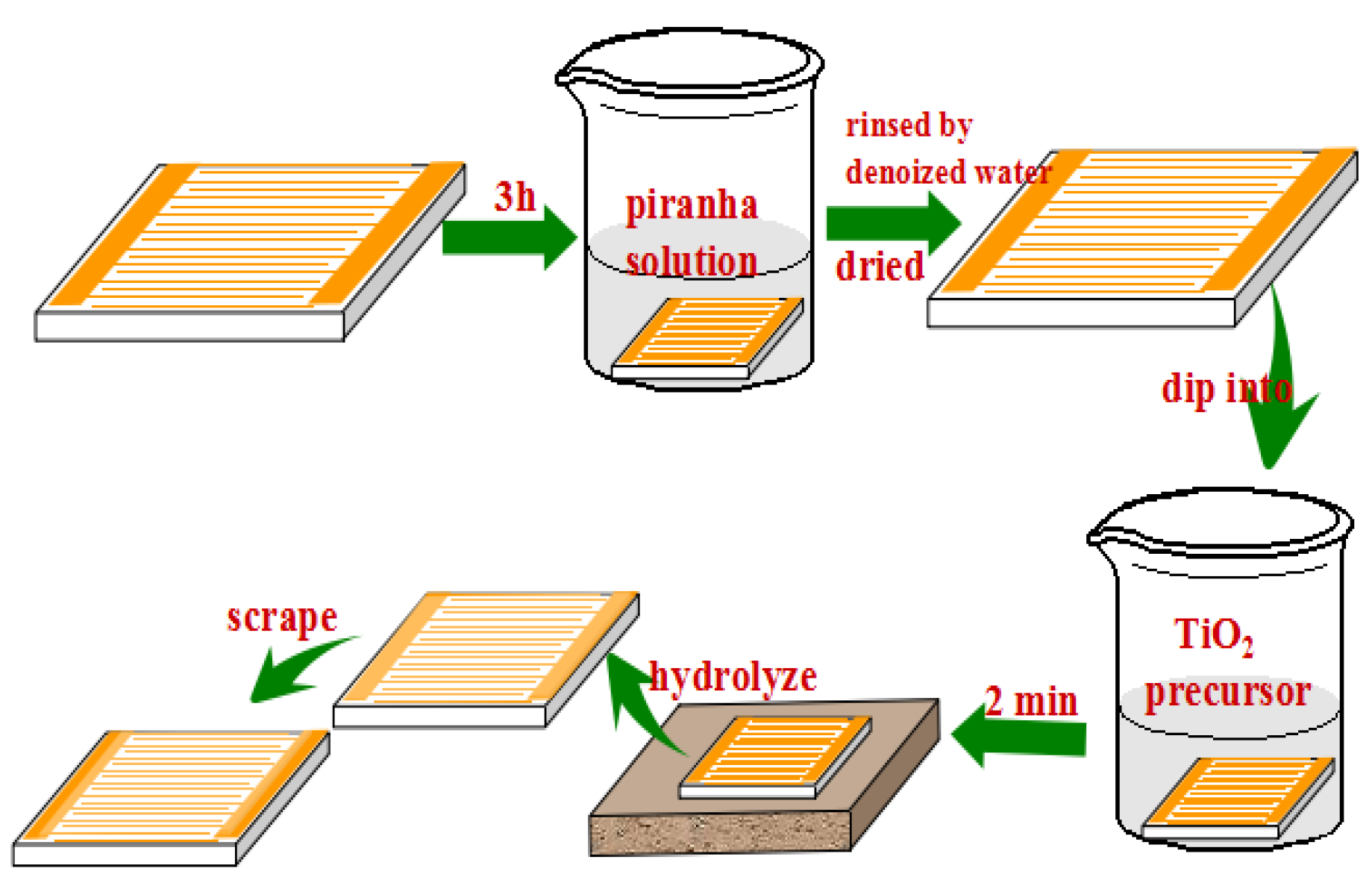
2.1. Fabrication of the Gas Sensor

The TiO2 gas sensor was prepared by the in-situ method showed in Scheme 1. An interdigitated Au electrode (15 mm × 10 mm, the gap size of 0.15 mm) deposited on the alumina (α-Al2O3) substrate was used as the substrate for the gas sensor. The electrode was first pretreated subsequently with acetone, ethanol, and deionized water, and then treated with piranha solution (30% H2O2:98% H2SO4 equivalent to 3:7 v/v) for 3 h in order to increase the hydrophilous character of the electrode surface [29]. The electrode was rinsed several times with deionized water and dried in the oven at 80 °C. In the second step, the clean electrode was dipped into a precursor solution containing a mixture of titanium isopropoxide and ethanol (1:10 v/v) for 2 min. Then, the electrode was put on a smooth table to rest and be hydrolyzed naturally through the air humidity. In the final step, the electrode was calcinated at 500 °C for 2 h at a heating rate of 1 °C·min−1, and then let to cool down to room temperature. The obtained TiO2 gas sensor is labeled as TiO2-I.
For characterization and testing purposes, a TiO2 powder sample labeled as TiO2 (in-situ) was prepared using the above precursor solution, then exposed to air and subsequent hydrolization and calcination processes.
For comparative purposes, another TiO2 sensor device was fabricated by the drop-coating method reported previously [31]. Precisely, A 30 mg of commercial TiO2 powder (99.8 wt% anatase, 5–10 nm, Aladdin Chemistry Co. Ltd., Shanghai, China) was dispersed in 1 mL terpineol (Chengjie Chemistry Co. Ltd., Shanghai , China) solvent to obtain a TiO2 suspension. The interdigitated Au electrode, subsequently pretreated by ultrasonic treatment in ethanol (99.7% purity) and deionized water then dried in the oven, was treated with 50 μL of the obtained TiO2 suspension by dropping the suspension onto the clean electrode surface. The coated electrode coated was then dried at 100 °C for 1 h and calcinated in air at 350 °C for 3 h (heating rate 2 °C·min−1). The electrode was left to cool down to room temperature, and the resulting sensor device was labeled as TiO2-D. It is worth noting that the corresponding TiO2 powder sample was labeled TiO2 (commercial).

2.2. Characterization

The phase and crystal structure of TiO2 powder samples were characterized by X-ray diffraction (XRD, D8 Advance, Brucker, Karlsruhe, Germany) having Cu Kα radiation. UV-vis diffuse reflectance spectra (UV-vis DRS) of TiO2 sensor film samples were recorded with UV-vis spectrophotometer (Cary-500, Varian Co., Guangzhou, China). Surface morphology of TiO2 sensor (film) samples was performed with Scanning Electron Microscopy (SEM) (Hitachi S4800, Hitachi, Tokyo, Japan).

2.3. Photoelectrochemical Measurement

The electrochemical properties of the samples were performed with an electrochemical analyzer having a three-electrode configuration. A fluorine-doped tin oxide (FTO) conductive glass coated with the material film was used as a working electrode, Pt wire as a counter-electrode, and Ag/AgCl (in saturated KCl (aq)) as a reference electrode. An aqueous solution of Na2SO4 (0.02 M) was used as an electrolyte. The working electrodes were prepared by drop-coating, where the FTO conductive glass electrodes were first washed in an ultrasonic bath with ethanol, deionized water, and then dried at 80 °C for 2 h. A 5 mg powder sample of TiO2 was added to 1 mL absolute DMF to make a slurry, and the suspension was then dispersed in an ultrasonic bath for over 3 h. The resulting slurry suspension was injected uniformly onto the conductive surface of 2.5 cm × 1.0 cm FTO glass electrode with the cell size of 5 mm × 5 mm. To obtain conductive working electrodes, the non-conductive nail polish was brushed coating on the conductive surface of FTO glass. The coated FTO glass electrode was then dried at room temperature for about 12 h. The transient photocurrent response for TiO2 stacks in the air was recorded on an electrochemical analyzer (Epsilon, BAS, USA) at the operation voltage of 0.5 V with point light as a light source. The electrochemical impedance spectroscopy (EIS) measurements were performed in a three-electrode cell and measurements recorded with Epsilon.

2.4. Testing of the Gas Sensors

The gas sensing properties of the films were investigated in a chamber made of stainless steel having a total volume of 100 mL. The response of the sensor films to gas was measured by aJF02Egas sensing test system (GuiYanJinFeng Tech. Co. Ltd., Kunming, China) at controlled voltage of 8.5 V. During the tests, the irradiation source was emitted by four UV lamps (4 W, Philips TL/05, PHILIPS, Poland) having wavelength set at 365 nm and the estimate total light intensity on the sensor surface was about 7.3 mW·cm−2. The light distance between diode and the sensor sample was about 4.5 cm. During this process, high purity N2 or air was used as background atmosphere. The air atmosphere was a synthetic air consisted of 20.5 vol% O2 and 79.5 vol% N2. Prior to any measurement, the sensor films were maintained at temperatures of 200 °C for 1 h in the corresponding background atmosphere (N2 or the synthetic air) and then cooled down to room temperature. Afterward, a probe gas H2 diluted in gas high purity N2 was introduced into the chamber at a flow rate of 250 mL·min−1 instead of the background atmosphere. Since the gas sensitivity of two samples to H2 was weak (the response limit of H2 concentration was about 5000 ppm, the detailed testing curves are not shown here), the H2 concentration was controlled at 20,000 ppm so as to clearly identify the differences between two samples. The response of the sensors to H2 was reflected in the variation of the impedance spectroscopy data induced by changes in surface conductivity (the highest detection limit is 106 KΩ). The gas sensing response (Sr) of the sensor was defined as: Sr = R0/Rgas, where R0 and Rgas were the impedance values measured in the background atmosphere and in the testing gas [31], respectively. Herein, the value of Sr may reflect the gas sensing performance of the sensor to the probe gas.
Moreover, the thermal responses to H2 of the sensor films were also performed at the same condition under no UV irradiation. Here, the film samples were maintained at 400 °C.
Since the metal oxide based gas sensors are sensitive to humidity, the relative humidity during the gas testing was carried out by a thermo-hygrometer, and the relative humidity during the testing process kept at about 74%.

3. Results and Discussion

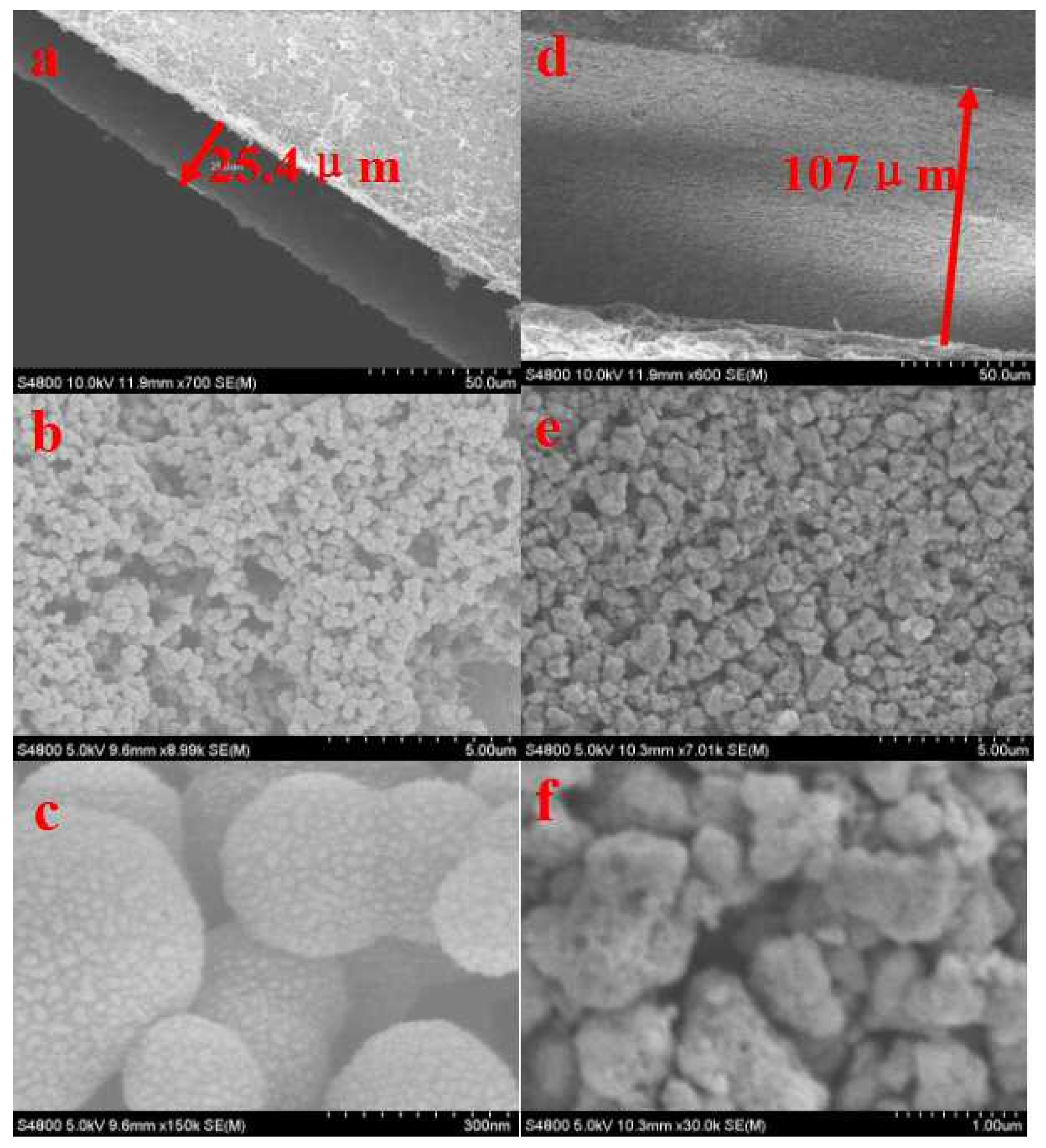
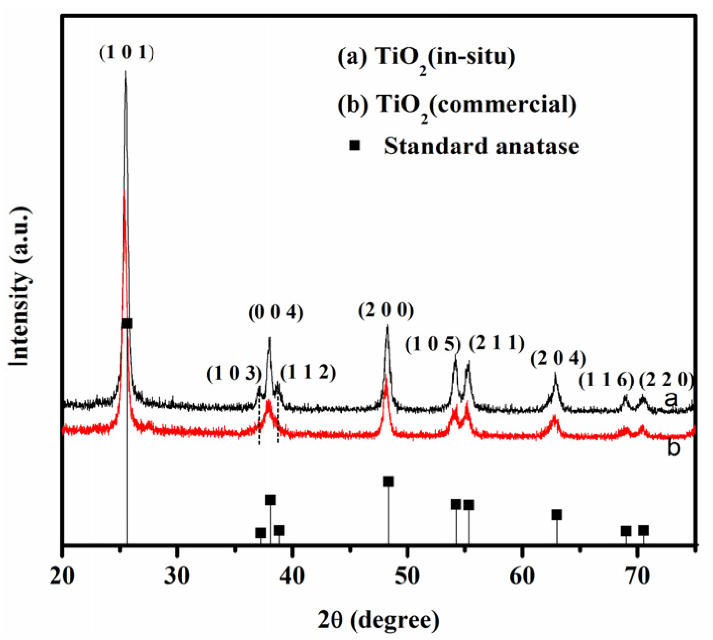
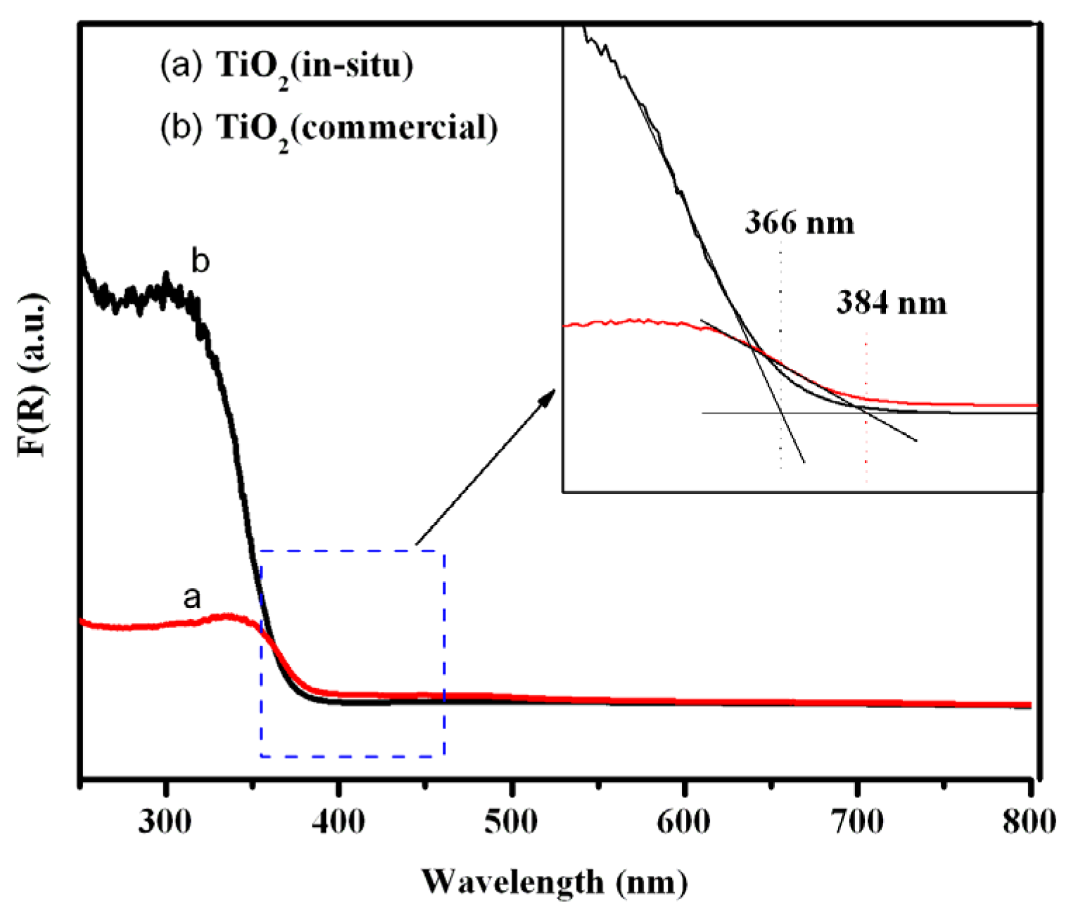
3.1. Properties of TiO2 Sensor Films

Figure 1 shows the surface morphology of the TiO2 sensor films. For the TiO2-I, a film with 25.4 μm thickness was deposited on the electrode surface (Figure 1a). As shown in Figure 1b,c, the TiO2 film was mainly composed of overlaid TiO2 microspheres with sizes ranging from 200 to 300 nm. Moreover, a porous structure could be seen among the adjacent microspheres that may contribute to an increase in the surface area that eventually would be conductive to adsorb more of the probe gas molecules [52]. In the TiO2-D sample, the TiO2 film loaded on the electrode substrate was mainly composed of nanoparticles stacked by a large of random granular (Figure 1d). The TiO2-D sensor film was about 109 μm, which was thicker than TiO2-I gas sensor. Figure 1e,f illustrates that the TiO2 nanoparticles underwent an aggregation after the calcination process of the substrates. TiO2 (commercial) was 5–10 nm before calcined, it may aggregate on the substrate result in the TiO2 nanoparticles were not uniform in size, which bank up the thick film. Considering that the morphology of the films may play an important role in the sensor characteristics including the sensitivity [15,21,25,26], the morphological differences between TiO2-I and TiO2-D based samples may be one of the important reasons leading to differences in sensitivities between the sensors.
Since the location of the XRD peaks of α-Al2O3 [53] and Au [20] are very close to those of anatase TiO2, the XRD patterns of the two TiO2 powder samples without electrode substrate (containing α-Al2O3 and Au components) were recorded. As seen in Figure 2, Both TiO2 (in-situ) and TiO2 (commercial) showed a number of characteristic diffraction peaks located at 2θ = 25.37°, 37.8°, 48.1°, 54.0°, 55.1°, 62.8°, 68.8° and 72.3°, which could be attributed, respectively, to (101), (004), (200), (105), (211), (204), (116) and (220) crystal planes of anatase TiO2 (JCPDS card 75-1537). In addition, two small peaks at 36.9° and 38.6° in TiO2 (in-situ) could be assigned to (103) and (112) crystal planes of anatase TiO2, respectively. Note that the two peaks were too weak to be observed in TiO2 (commercial). Moreover, the two TiO2 samples owned the similar crystal sizes of anatase structure (19.6 nm of TiO2 (in-situ) vs. 18.2 nm of TiO2 (commercial)) according to the Debye–Scherrer formula. The similarity between the XRD features of both samples indicates that the TiO2 (in-situ) was formed in its pure anatase crystalline structure similar to the TiO2 (commercial) sample.
Figure 3 shows the UV-vis diffuse reflectance spectra of TiO2-I and TiO2-D samples. Both samples represent the TiO2 intrinsic absorption band in the ultraviolet region. If compared to TiO2-D, the TiO2-I exhibits weak absorption intensity, it may due to the TiO2-I film was thinner than the TiO2-D. While a red shift in the basal absorption region from round 366 nm to 380 nm was observed, it could be attributed to the microsphere structure of the TiO2-I sample observed in Figure 1 [54,55]. This indicates that TiO2-I has a wider absorption UV-light region than TiO2-D, which may result in a stronger photo-response during gas sensing testing [56].

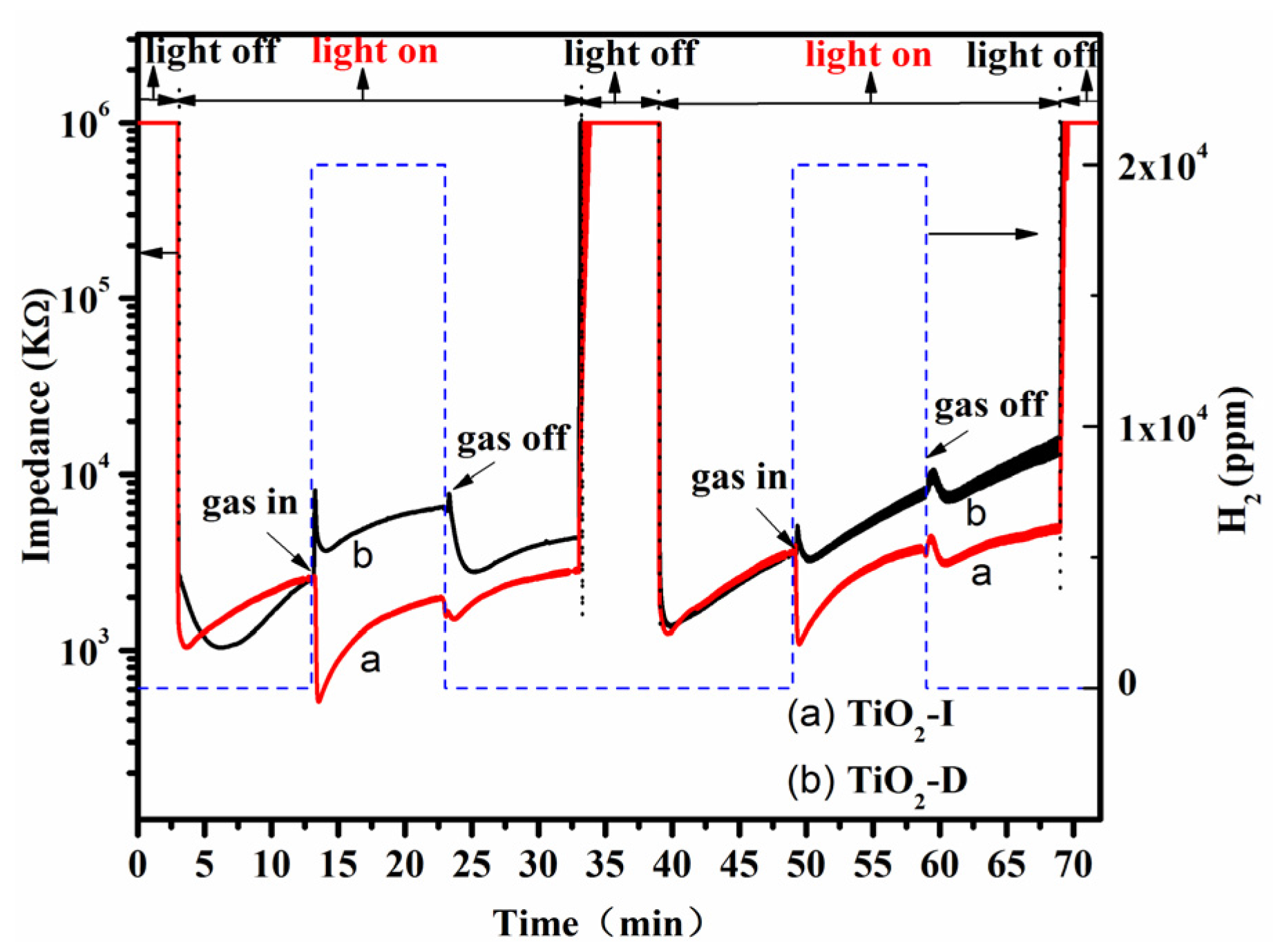
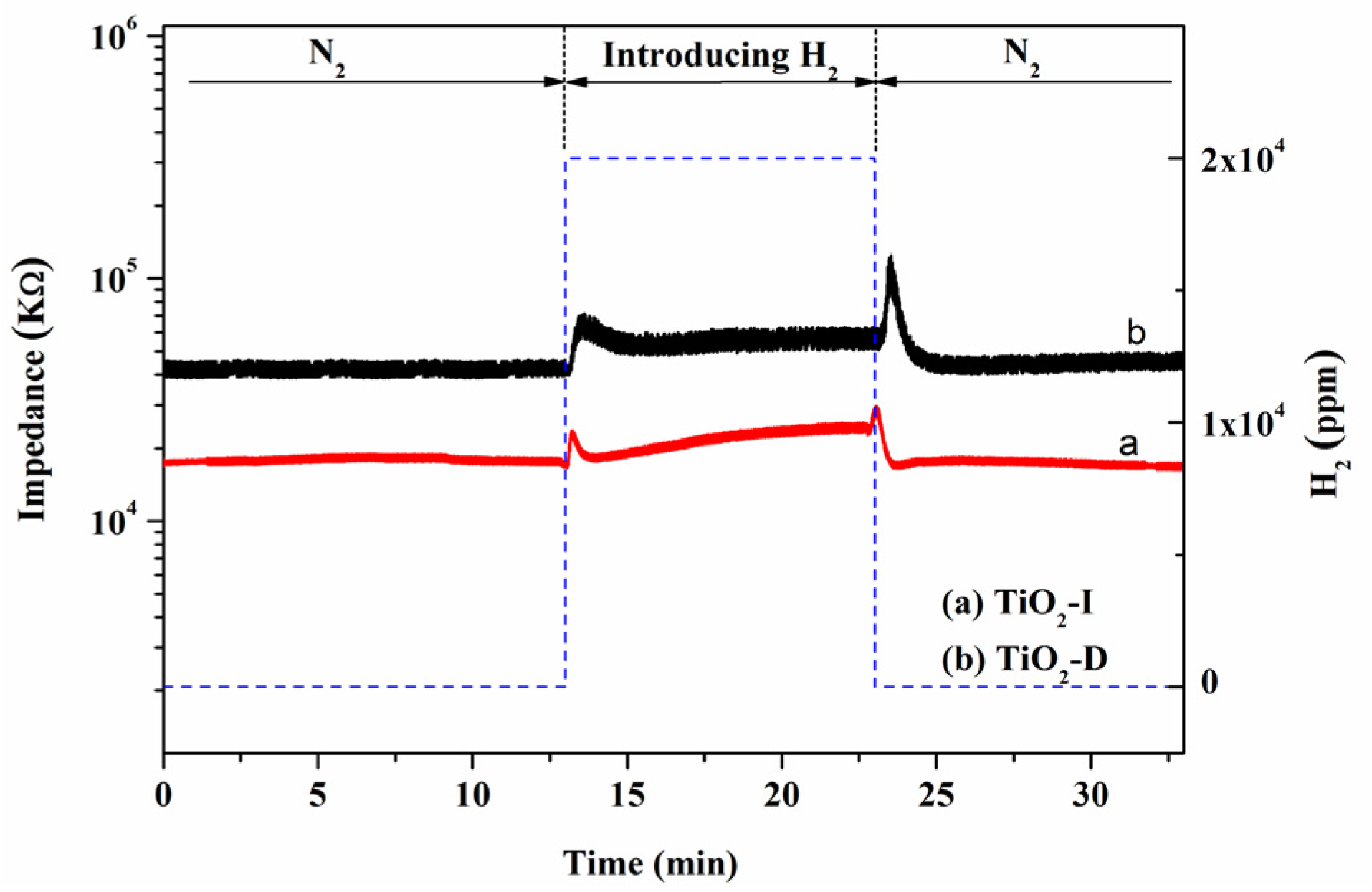
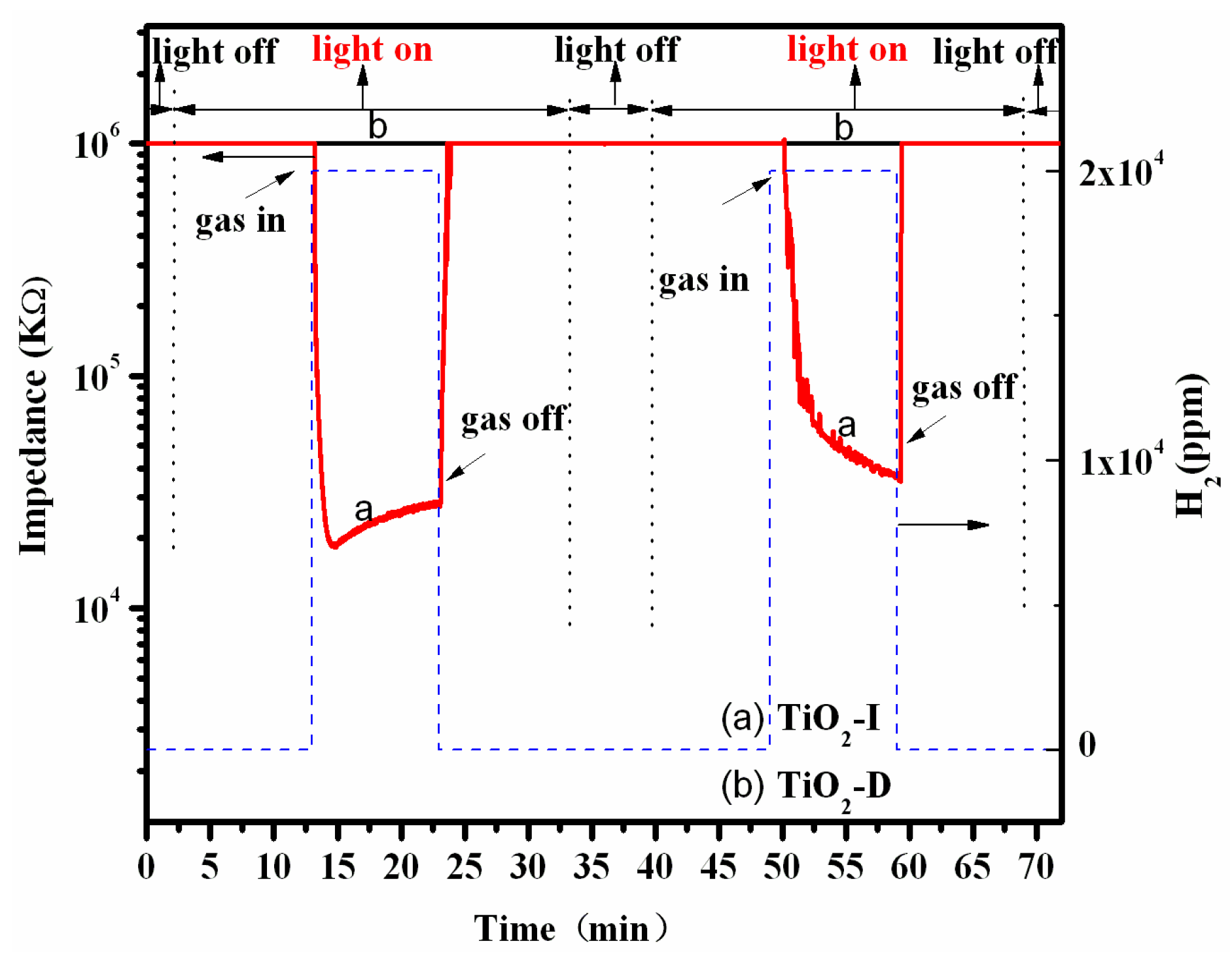
3.2. Performance of TiO2 Gas Sensor

Figure 4 shows the photo-assisted gas sensing performance of TiO2-I and TiO2-D samples to H2 in N2 atmospheres at room temperature under the UV irradiation. It could be seen that the impedance of both TiO2-I and TiO2-D decreased rapidly upon the introduction of the UV light under the pure N2 atmosphere, then increased gradually during the following time of the irradiation, which is in agreement with our previous report [31]. The reason for this may have to do with the UV light that could excite TiO2 to produce photo-generated electrons. In turn, this resulted in an enhancement in the surface electron density of TiO2 nanoparticles and a decrease in the impedance of the sample. However, UV light might cause the change in the surface state of TiO2 (in fact, the process of UV irradiating TiO2 can be regarded as a process of TiO2 reduced by UV light), the generation of electrons, the recombination of electrons with holes, the capture of electrons by defects or surface hydroxyls, and the transfer of electrons will make some changes with the duration of introducing UV light, especially under the bias voltage. Therefore, the impedance of TiO2 sensor sample increased slowly with the duration of UV irradiation [57]. With the introduction of H2, the impedance of TiO2-I sample decreased rapidly but that of TiO2-D sample increases. The latter indicates that the adsorbed H2 could offer electrons to TiO2-I but accept electrons from the TiO2-D sample [57]. Moreover, TiO2-I exhibited a higher response to H2 than TiO2-D (Table 1). As can be seen in Table 1, the value of the gas sensing response of the TiO2-I in first circle was about 4.856, while TiO2-D was just 0.738. This illustrates that the gas sensing performance of TiO2-I to H2 may be superior to TiO2-D in N2 atmospheres at room temperature under the UV irradiation. By removing H2, the impedance of TiO2-D decreases under the UV irradiation, confirming that the adsorbed H2 could accept electrons from TiO2-D. On the other hand, the TiO2-I sample also exhibited a slight decrease in impedance with the removal of H2, indicating that H2 could also accept electrons from TiO2-I during the late stages of the process. After H2 stream was cut off, the impedance of TiO2-I increased slowly with the duration of UV irradiation in N2 atmosphere, which present the same trend as that process prior to introducing H2. Note that TiO2-I also exhibited a shorter response time and a shorter recovery time as compared to TiO2-D (seen in Table 1).
Additionally, TiO2-I showed a change in impedance (gas sensitivity) in the second cycle similar to the one observed during the first cycle, but the TiO2-D sample showed a different response from the one seen during the first cycle (changes from a negative to a positive response). Furthermore, the gas sensing response value of TiO2-I was also bigger than TiO2-D. This means that the TiO2-I sample has a more stable sensitivity to H2 in N2 atmosphere under the UV irradiation than the TiO2-D.
Moreover, the thermal sensing properties of two samples were also tested. As seen in Figure 5, both the TiO2-I and TiO2-D samples exhibited a weak response to H2 in N2 atmosphere with the applied voltage of 8.5 V under no UV irradiation at 400 °C. Moreover, the response value of each sample was much weaker than the respective response value at the same condition under UV irradiation (see Figure 4), indicating that the photo-assisted sensitivity of each sample may be stronger than the respective thermal (chemical) sensitivity at 400 °C. Moreover, the thermal sensitivity of TiO2-I at 400 °C was also stronger than that at 250 °C, 300 °C and 350 °C (see Figure S1). Note that the thermal response values of two samples were more stable than the photo-assisted response values. However, the thermal sensitivities of two samples towards H2 are lower than other H2 gas sensors using TiO2 nanostructures in the literatures, e.g., TiO2 nanotube sensors [51]. Considering the promotion effect of UV light on the H2 sensitivities of the two above TiO2 samples in this work, we think that the gas sensitivities of the TiO2 nanotube sensors may be further enhanced by introducing UV light.
Furthermore, the photo-assisted gas sensitivities to H2 of both TiO2-I and TiO2-D samples were also performed in the air atmosphere instead of N2. As displayed in Figure 6, both TiO2-I and TiO2-D showed no response in the air atmosphere when irradiated under the UV irradiation. Upon the introduction of H2, TiO2-D still showed no response as there is no decrease in the impedance. However, the TiO2-I sample exhibited an obvious response to H2 as a rapid decrease in the impedance could be noticed. Because the base impedance value reached the detection limit, the response value was very large respect to Table 1. With the removal of H2, the impedance of TiO2-I rapidly increased again. Moreover, the TiO2-I sample still illustrated a response to H2 in the air atmosphere under the UV irradiation during the second cycle. This above result indicated that the TiO2-I sensor could be reused to gas sensing response to H2, while TiO2-D could not. However, the response transition of TiO2-I sample in the second cycle was different from that in the first cycle, i.e., the impedance of TiO2-I sample increased slowly during the process of introducing H2 in the first cycle, but decreased slowly in the second cycle.
In other words, if compared to the drop-coating prepared TiO2 sensor (TiO2-D), the in-situ prepared TiO2 sensor (TiO2-I) exhibited a superior gas sensitivity towards H2 under the UV irradiation at room temperature in both N2 and synthetic air atmospheres. The uniform TiO2 microspheres present in the TiO2-I sample might play a significant role in the superior efficiency of the photo-assisted gas sensors. This latter may be attributed to the microsphere structure that could promote the generation and transfer of the photo-generated electrons under the UV radiation [55]. Although the presence of O2 could weaken the photo-assisted response to H2 in TiO2 due to the adsorbed O2 molecules that could accept the photo-generated electrons from TiO2 [31], the TiO2-I sample still present an effective response to H2 in the air atmosphere (Figure 6). This indicates that the presence of H2 may suppress the ability of O2 in accepting the generated electrons from TiO2 over TiO2-I. As for the different response transitions of TiO2-I towards H2 between the first cycle and the second cycle (see Figure 6), it may be attributed to the competitive adsorption of H2 and O2 at different adsorption sites of TiO2 induced by the order of adsorbing two gases. A detailed explanation needs to be further investigated. By contrast, TiO2-D shows practically no response to H2 in the air atmosphere under the UV irradiation (Figure 6), indicating that the presence of H2 does not suppress the behavior of the adsorbed O2 to accept electrons from TiO2. This positive result of TiO2-I sample towards H2 in air atmosphere shows that the change of structure or morphology of TiO2 might cause a transformation in its gas sensing property. Of course, the thickness difference between TiO2-I and TiO2-D (see Figure 2) may also cause the change in H2 sensing property of two samples according to the report of Sakai et al. [58]. However, it was difficult to obtain the same thickness of TiO2 film for TiO2-I and TiO2-D samples due to the different preparing method. Moreover, the different nanostructures and morphologies existed in two samples also make it difficult to compare the changes of sensitivity induced by TiO2 film thickness. The detailed reason needs to be investigated in the further work.

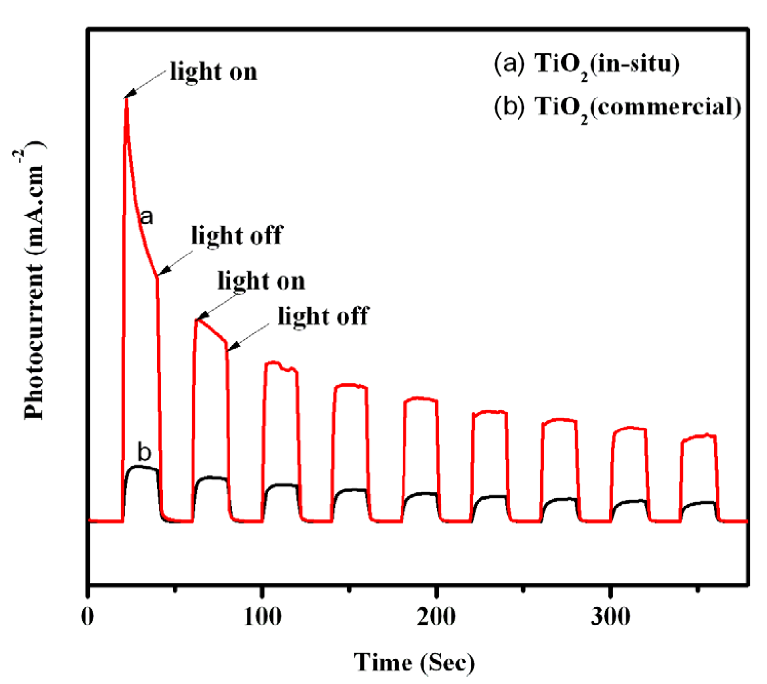
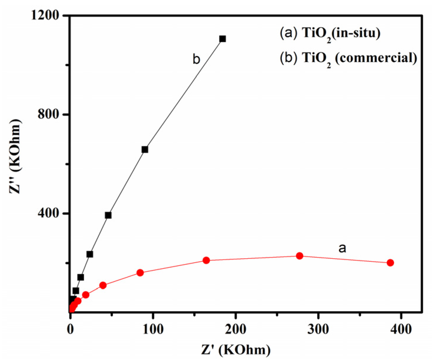
3.3. Photoelectrochemical Properties of TiO2

Yamazoe et al. [59] have reported that the gas sensing performance of a conductometric semiconductor sensor is mainly determined by the following three key factors: (a) a base oxide with high mobility of conduction electrons and satisfactory stability; (b) a foreign receptor which enhances surface reactions or adsorption of target gas; and (c) the fabrication of a highly porous, thin sensing body of oxide. This indicates that the grain size of oxide will exert an effect on the gas sensitivity by adsorbing target gas at the surface of each oxide grain and the electron transfer between each grain boundary. Considering that the structure and grain size of TiO2-I were different from those of TiO2-D, the electron transfer behaviors of two samples under UV irradiation were compared by the photoelectrochemical measurements.
Figure 7 illustrates the photocurrent results of the TiO2 (in-situ) and TiO2 (commercial) electrodes upon ON and OFF time of the UV irradiation. Both samples exhibited an increase in the photocurrent intensities under the UV irradiation and a decrease upon removal of the UV light. This indicates that not only extra electrons could be produced over TiO2 under UV irradiation, but also the photo-generated electrons could undergo a transfer from the TiO2 surface to the indium tin oxide substrates in both electrodes. Obviously, it could be observed that the photocurrent of the TiO2 (in-situ) electrode is much larger than the one obtained with the TiO2 (commercial) electrode. With the irradiation prolonged, more and more photo-generated electrons and holes recombined or be captured on TiO2 surface due to the reduction of TiO2 by UV light [57], which resulted in the photocurrent decay. Note that the photocurrent value of TiO2 (in-situ) is larger than that of TiO2 (commercial), indicating that the recombination rate of TiO2 (in-situ) is lower than that of TiO2 (commercial).
This above result demonstrates that the TiO2 (in-situ) electrode was more efficient in the generation, separation, and transfer of the photo-generated electron–hole pairs [47,54,60] when compared with TiO2 (commercial). That is to say, the one-step method prepared sensor sample might form a strong interaction between TiO2 nanoparticle and electrode substrate or among TiO2 nanoparticles, which would be propitious to the electron transfer and the charge separation. This could be the reason of why the in-situ prepared TiO2 sensor (TiO2-I) displays superior gas sensing performance towards H2 than the drop-coating TiO2 sensor (TiO2-D). In addition, the different thickness and roughness of the gas sensing layer between two samples might also somewhat lead to the observed differences. A more description needs to be further investigated.
The above results of electron transfer were further confirmed by EIS measurements, an effective tool that provides useful information on impedance changes in modified electrode surfaces [61,62]. In general, a smaller semi-circle in the EIS Nyquist plots indicates the smaller resistance at the material interface, and thus more effective interfacial charge transfer at the electrode interface [62,63]. As shown in Figure 8, the size of the semi-circle radius on the Nyquist plots of TiO2 (in-situ) was smaller than the one obtained with TiO2 (commercial) electrode. This reveals that the TiO2 (in-situ) electrode achieves a better surface electron transfer. In fact, Ding et al. [64] have reported that adding one layer of TiO2 nano-crystalline as a linking bridge between TiO2 sub-microspheres layer and substrates could promote a better electron transfer through a high specific surface area and effective light scattering. Accordingly, it is possible that the unique nanostructure of TiO2 films formed by uniform TiO2 microspheres in the in-situ prepared TiO2 sensor could benefit the electron transfer and charge separation between TiO2 and substrates or among TiO2 nanoparticles, resulting in the higher photo-assisted gas sensitivity. This result also shows that a new photo-electrochemical measurement may be used to investigate the electron transfer behavior in TiO2 or other semiconductor gas sensors.
Of course, this prepared TiO2 sensor sample cannot yet be applied for detecting H2. It still needs to be further improved in some cases, especially its sensing stability. However, the positive result of response to H2 in air showed that this work might offer an approach to improve the photo-assisted sensing properties of TiO2 and other semi-conductors by changing their structures and morphologies. We also hope that this photo-assisted gas sensing property will occur on other TiO2 nanostructure sensors with the better thermal gas sensitivity, such as TiO2 nanotube sensor. The related work will be processed in the near future.

4. Conclusions

From the present investigation the following conclusions can be drawn:
  • A TiO2-I film sensor formed by uniform TiO2 microspheres, fabricated by a facile in-situ method, which exhibited an effective sensitivity towards H2 in both N2 atmosphere and synthetic air at the room temperature under UV irradiation.
  • A TiO2-D film sensor, prepared by drop-coating method, exhibited an apparent sensitivity towards H2 only in N2 atmosphere but not in synthetic air under UV irradiation.
  • The better photo-assisted sensitivity of TiO2-I could be attributed to the more effective charge transfer at TiO2 interface, which can be evaluated by the photoelectrochemical measurement.
  • The effective charge transfer behaviors in TiO2-I could be originated from the uniform TiO2 nanosphere structure.
  • This study shows that changing the structure and morphology of film sensor (e.g., preparing a uniform nanostructure) maybe improve the photo-assisted sensing properties of TiO2 and other semi-conductor sensors by enhancing electron transfer efficiency.

Supplementary Materials

The following are available online at https://www.mdpi.com/1424-8220/16/8/1249/s1, Figure S1: Gas sensing process to H2 in N2 atmosphere at different temperatures without UV light over TiO2-I sample. The solid curves denote the impedance module of samples as function of time, and the dotted line denotes the concentration of H2 during the testing process. However, the testing process at 450 °C could not be performed due to the temperature limit of the chamber.

Acknowledgments

This work was financially supported by the National Natural Science Foundation of China (no. 21273037), the National Basic Research Program of China (973 Program, no. 2014CB239303) and the Science & Technology Plan Project of Fujian Province (no. 2014Y2003).

Author Contributions

Xiaoying Peng performed the experiments, Zhongming Wang assisted in performing the experiments (responsibility for gas sensing testing), Pan Huang assisted in performing the experiments (Photoelectrochemical properties of TiO2), Xun Chen assisted in the analysis of XRD data, Wenxin Dai guided in this research, and Xianzhi Fu assisted in the analysis of gas sensing results.

Conflicts of Interest

The authors declare no conflict of interest.

References

  1. Usha, S.P.; Mishra, S.K.; Gupta, B.D. Fiber optic hydrogen sulfide gas sensors utilizing ZnO thin film/ZnO nanoparticles: A comparison of surface plasmon resonance and lossy mode resonance. Sens. Actuators B Chem. 2015, 218, 196–204. [Google Scholar] [CrossRef]
  2. Cuong, N.D.; Khieu, D.Q.; Hoa, T.T.; Quang, D.T.; Viet, P.H.; Lam, T.D.; Hoa, N.D.; Hieu, N.V. Facile synthesis of α-Fe2O3 nanoparticles for high-performance CO gas sensor. Mater. Res. Bull. 2015, 68, 302–307. [Google Scholar] [CrossRef]
  3. Blais, F. Review of 20 years of range sensor development. J. Electron. Imaging 2004, 13, 231–243. [Google Scholar] [CrossRef]
  4. VinothKumar, J.; Maldonado, A.; Olvera, M. A simple and cost-effective zinc oxide thin film sensor for propane gas detection. Mater. Lett. 2015, 157, 169–171. [Google Scholar]
  5. Grieshaber, D.; MacKenzie, R.; Vörös, J.; Reimhult, E. Electrochemical biosensors—Sensor principles and architectures. Sensors 2008, 8, 1400–1458. [Google Scholar] [CrossRef] [Green Version]
  6. Homola, J. Surface plasmon resonance sensors for detection of chemical and biological species. Chem. Rev. 2008, 108, 462–493. [Google Scholar] [CrossRef] [PubMed]
  7. Fujishima, A.; Honda, K. Electrochemical Photolysis of Water at a Semiconductor Electrode. Nature 1972, 238, 37–38. [Google Scholar] [CrossRef] [PubMed]
  8. Grätzel, M. Photoelectrochemical cells. Nature 2001, 414, 338–344. [Google Scholar] [CrossRef] [PubMed]
  9. Konstantinou, I.K.; Albanis, T.A. TiO2-assisted photocatalytic degradation of azo dyes in aqueous solution: Kinetic and mechanistic investigations: A review. Appl. Catal. B Environ. 2004, 49, 1–41. [Google Scholar] [CrossRef]
  10. Ni, M.; Leung, M.K.H.; Leung, D.Y.C.; Sumathy, K. A review and recent developments in photocatalytic water-splitting using TiO2 for hydrogen production. Renew. Sustain. Energy Rev. 2007, 11, 401–425. [Google Scholar] [CrossRef]
  11. Millis, A.; Hunte, S.L. An overview of semiconductor photocatalysis. J. Photochem. Photobiol. A Chem. 1997, 108, 1–35. [Google Scholar] [CrossRef]
  12. Hazra, A.; Das, S.; Kanungo, J.; Sarkar, C.K.; Basu, S. Studies on a resistive gas sensor based on sol–gel grown nanocrystalline p-TiO2 thin film for fast hydrogen detection. Sens. Actuators B Chem. 2013, 183, 87–95. [Google Scholar] [CrossRef]
  13. Lim, S.K.; Hong, S.H.; Hwang, S.H.; Choi, W.M.; Kim, S.H.; Park, H.W.; Jeong, M.G. Synthesis of Al-doped ZnO Nanorods via Microemulsion Method and Their Application as a CO Gas Sensor. J. Mater. Sci. Tech. 2015, 1, 639–644. [Google Scholar] [CrossRef]
  14. Bai, J.; Zhou, B. Titanium dioxide nanomaterials for sensor applications. Chem. Rev. 2014, 114, 10131–10176. [Google Scholar] [CrossRef] [PubMed]
  15. Moon, J.; Park, J.A.; Lee, S.J.; Zyung, T.; Kim, I.D. Pd-doped TiO2 nanofiber networks for gas sensor applications. Sens. Actuators B Chem. 2010, 149, 301–305. [Google Scholar] [CrossRef]
  16. Sharma, K.R.; Bhatnagar, M.C.; Sharma, G.L. Mechanism of highly sensitive and fast response Cr doped TiO2 oxygen gas sensor. Sens. Actuators B Chem. 1997, 45, 209–215. [Google Scholar] [CrossRef]
  17. Comini, E.; Sberveglieri, G.; Ferroni, M.; Guidi, V.; Martinelli, G. Response to ethanol of thin films based on Mo and Ti oxides deposited by sputtering. Sens. Actuators B Chem. 2003, 93, 409–415. [Google Scholar] [CrossRef]
  18. Ruiz, A.M.; Cornet, A.; Morante, J.R. Study of La and Cu influence on the growth inhibition and phase transformation of nano-TiO2 used for gas sensors. Sens. Actuators B Chem. 2004, 100, 256–260. [Google Scholar] [CrossRef]
  19. Bonini, N.; Carotta, M.C.; Chiorino, A.; Guidi, V.; Malagù, C.; Martinelli, G.; Paglialonga, L.; Sacerdoti, M. Doping of a nanostructured titania thick film: Structural and electrical investigations. Sens. Actuators B Chem. 2000, 68, 274–280. [Google Scholar] [CrossRef]
  20. Zhu, Z.; Chang, J.L.; Wu, R.J. Fast ozone detection by using a core–shell Au@TiO2 sensor at room temperature. Sens. Actuators B Chem. 2015, 214, 56–62. [Google Scholar] [CrossRef]
  21. Plecenik, T.; Moško, M.; Haidry, A.A.; Ďurina, P.; Truchlý, M.; Grančič, B.; Gregor, M.; Roch, T.; Satrapinskyy, L.; Mošková, A.; et al. Fast highly-sensitive room-temperature semiconductor gas sensor based on the nanoscale Pt–TiO2–Pt sandwich. Sens. Actuators B Chem. 2015, 207, 351–361. [Google Scholar] [CrossRef]
  22. Kobayashi, H.; Kishimoto, K.; Nakato, Y.; Tsubomura, H. Mechanism of hydrogen sensing by Pd/TiO2 Schottky diodes. Sens. Actuators B Chem. 1993, 13, 125–127. [Google Scholar] [CrossRef]
  23. Walton, R.M.; Liu, H.; Gland, J.L.; Schwank, J.W. Resistance measurements of platinum-titania thin film gas detectors in ultra-high vacuum (UHV) and reactive ion etcher (RIE) systems. Sens. Actuators B Chem. 1997, 41, 143–151. [Google Scholar] [CrossRef]
  24. Mor, G.K.; Varghese, O.K.; Paulose, M.; Ong, K.G.; Grimes, C.A. Fabrication of hydrogen sensors with transparent titanium oxide nanotube-array thin films as sensing elements. Thin Solids Films 2006, 496, 42–48. [Google Scholar] [CrossRef]
  25. Gao, M.; Ito, A.; Goto, T. Preparation of γ-Al2O3 films by laser chemical vapor deposition. Appl. Surf. Sci. 2015, 340, 160–165. [Google Scholar] [CrossRef]
  26. Sonker, R.K.; Sabhajeet, S.R.; Singh, S.; Yadav, B.C. Synthesis of ZnO nanopetals and its application as NO2 gas sensor. Mater. Lett. 2015, 152, 189–191. [Google Scholar] [CrossRef]
  27. Nikfarjam, A.; Salehifar, N. Improvement in gas-sensing properties of TiO2 nanofiber sensor by UV irradiation. Sens. Actuators B Chem. 2015, 211, 146–156. [Google Scholar] [CrossRef]
  28. Gong, J.; Li, Y.H.; Chai, X.S.; Hu, Z.S.; Deng, Y.L. UV-light-activated ZnO fibers for organic gas sensing at room temperature. J. Phys. Chem. C 2010, 114, 1293–1298. [Google Scholar] [CrossRef]
  29. Camagni, P.; Fanglia, G.; Galinetto, P.; Perego, C.; Samoggia, G.; Sberveglieri, G. Photosensitivity activation of SnO2 thin film gas sensors at room temperature. Sens. Actuators B Chem. 1996, 31, 99–103. [Google Scholar] [CrossRef]
  30. Cao, C.L.; Hu, C.H.; Wang, X.; Wang, S.X.; Tian, Y.S.; Zhang, H.L. UV sensor based on TiO2 nanorod arrays on FTO thin film. Sens. Actuators B Chem. 2011, 156, 114–119. [Google Scholar] [CrossRef]
  31. Geng, Q.; He, Z.J.; Chen, X.; Dai, W.X.; Wang, X.X. Gas sensing property of ZnO under visible light irradiation at room temperature. Sens. Actuators B Chem. 2013, 18, 293–297. [Google Scholar] [CrossRef]
  32. Chen, H.; Liu, Y.; Xie, C.S.; Wu, J.; Zeng, D.W.; Liao, Y.C. A comparative study on UV light activated porous TiO2 and ZnO film sensors for gas sensing at room temperature. Ceram. Int. 2012, 38, 503–509. [Google Scholar] [CrossRef]
  33. Su, P.G.; Shiu, C.C. Flexible H2 sensor fabricated by layer-by-layer self-assembly of thin films of polypyrrole and modified in situ with Pt nanoparticles. Sens. Actuators B Chem. 2011, 157, 275–281. [Google Scholar] [CrossRef]
  34. Rella, R.; Spadavecchia, J.; Manera, M.G.; Capone, S.; Taurino, A.; Martino, M.; Caricato, A.P.; Tunno, T. Acetone and ethanol solid-state gas sensors based on TiO2 nanoparticles thin film deposited by matrix assisted pulsed laser evaporation. Sens. Actuators B Chem. 2007, 127, 426–431. [Google Scholar] [CrossRef]
  35. Kawano, T.; Chiamori, H.C.; Suter, M.; Zhou, Q.; Sosnowchik, B.D.; Lin, L.W. An Electrothermal Carbon Nanotube Gas Sensor. Nano Lett. 2007, 7, 3686–3690. [Google Scholar] [CrossRef] [PubMed]
  36. Vanaraja, M; Muthukrishnan, K.; Boomadevi, S.; Karn, R.K.; Singh, V.; Singh, P.K.; Pandiyana, K. Dip coated nanostructured ZnO thin film: Synthesis and application. Ceram. Int. 2016, 42, 4413–4420. [Google Scholar]
  37. Hübert, T.; Boon-Brett, L.; Black, G.; Banach, U. Hydrogen sensors—A review. Sens. Actuators B Chem. 2011, 157, 329–352. [Google Scholar] [CrossRef]
  38. Fadeyev, G.; Kalyakin, A.; Gorbova, E.; Brouzgou, A.; Demin, A.; Volkov, A.; Tsiakaras, P. A simple and low-cost amperometric sensor for measuring H2, CO, and CH4. Sens. Actuators B Chem. 2015, 221, 879–883. [Google Scholar] [CrossRef]
  39. Lee, E.B.; Hwang, I.S.; Cha, J.H.; Lee, H.J.; Lee, W.B.; Pak, J.J.; Lee, J.H.; Ju, B.K. Micromachined catalytic combustible hydrogen gas sensor. Sens. Actuators B Chem. 2011, 153, 392–397. [Google Scholar] [CrossRef]
  40. Kalyakin, A.; Fadeyev, G.; Demin, A.; Gorbova, E.; Brouzgou, A.; Volkov, A.; Tsiakaras, P. Application of Solid oxide proton-conducting electrolytes for amperometric analysis of hydrogen in H2+N2+H2O gas mixtures. Electrochim. Acta 2014, 141, 120–125. [Google Scholar] [CrossRef]
  41. Iwahara, H.; Asakura, Y.; Katahira, K.; Tanaka, M. Prospect of hydrogen technology using proton-conducting ceramics. Solids State Ion. 2004, 168, 299–310. [Google Scholar] [CrossRef]
  42. Schwandt, C.; Fray, D.J. The titanium/hydrogen system as the solid-state reference in high-temperature proton conductor-based hydrogen sensors. J. Appl. Electrochem. 2006, 36, 557–565. [Google Scholar] [CrossRef]
  43. Lee, J.; Shim, W.; Lee, E.; Noh, J.; Lee, W. Highly mobile palladium thin films on an elastomeric substrate: Nanogap-based hydrogen gas sensors. Angew. Chem. Int. Ed. 2011, 50, 5301–5305. [Google Scholar] [CrossRef] [PubMed]
  44. Jang, B.; Lee, K.; Noh, J.; Lee, W. Nanogap-based electrical hydrogen sensors fabricated from Pd-PMMA hybrid thin films. Sens. Actuators B Chem. 2014, 193, 530–535. [Google Scholar] [CrossRef]
  45. Dwivedi, D.; Dwivedi, R.; Srivastava, S.K. Sensing properties of palladium-gate MOS (Pd-MOS) hydrogen sensor-based on plasma grown silicon dioxide. Sens. Actuators B Chem. 2000, 71, 161–168. [Google Scholar] [CrossRef]
  46. Aroutiounian, V. Metal oxide hydrogen, oxygen and carbon monoxide sensorsfor hydrogen setups and cells. Int. J. Hydrog. Energy 2007, 32, 1145–1158. [Google Scholar] [CrossRef]
  47. Heszler, P.; Ionescu, R.; Llobet, E.; Reyes, L.F.; Smulko, J.M.; Kish, L.B.; Granqvist, C.G. On the selectivity of nanostructured semiconductor gas sensors. Phys. Status Solids B 2007, 244, 4331–4335. [Google Scholar] [CrossRef]
  48. Mor, G.K.; Varghese, O.K.; Paulose, M.; Shankar, K.; Grimes, C.A. A review on highly ordered, vertically oriented TiO2 nanotube arrays: Fabrication, material properties, and solar energy applications. Sol. Energy Mater. Sol. Cells 2006, 90, 2011–2075. [Google Scholar] [CrossRef]
  49. Roy, P.; Berger, S.; Schmuki, P. TiO2 nanotubes: Synthesis and applications. Angew. Chem. Int. Ed. 2011, 50, 2904–2939. [Google Scholar] [CrossRef] [PubMed]
  50. Paulose, M.; Varghese, O.K.; Mor, G.K.; Grimes, C.A.; Ong, K.G. Unprecedented ultra-high hydrogen gas sensitivity in undoped titania nanotubes. Nanotechnology 2006, 17, 398–402. [Google Scholar] [CrossRef]
  51. Moon, J.; Hedman, H.; Kemell, M.; Tuominen, A.; Punkkinen, R. Hydrogen sensor of Pd-decorated tubular TiO2 layer prepared by anodization with patterned electrodes on SiO2/Si substrate. Sens. Actuators B Chem. 2016, 222, 190–197. [Google Scholar] [CrossRef]
  52. Cui, C.; Qiu, Y.W.; Zhao, J.H.; Lu, B.Q.; Hu, H.H.; Yang, Y.N.; Ma, N.; Xu, S.; Xu, L.B.; Li, X.Y. A comparative study on the quantum-dot-sensitized. dye-sensitized and co-sensitized solar cells based on hollow spheres embedded porous TiO2 photoanodes. Electrochim. Acta 2015, 173, 551–558. [Google Scholar] [CrossRef]
  53. Li, B.; Shao, L.L. The identifying of Al2O3 and Al(OH)3 by XRD. Inorg. Chem. Ind. 2008, 40, 54–57. (In Chinese) [Google Scholar]
  54. Pal, S.; Laera, A.M.; Licciulli, A.; Catalano, M.; Taurino, A. Biphase TiO2 Microspheres with Enhanced Photocatalytic Activity. Ind. Eng. Chem. Res. 2014, 53, 7931–7938. [Google Scholar] [CrossRef]
  55. Zheng, X.Z.; Meng, S.G.; Chen, J.; Wang, J.J.; Xian, J.J.; Shao, Y.; Fu, X.Z.; Li, D.Z. Titanium dioxide photonic crystals with enhanced photocatalytic activity: Matching photonic band gaps of TiO2 to the absorption peaks of dyes. J. Phys. Chem. C 2013, 117, 21263–21273. [Google Scholar] [CrossRef]
  56. Dai, J.; Yang, J.; Wang, X.H.; Zhang, L.; Li, Y.J. Enhanced visible-light photocatalytic activity for selective oxidation of amines into imines over TiO2(B)/anatase mixed-phase nanowires. Appl. Surf. Sci. 2015, 349, 343–352. [Google Scholar] [CrossRef]
  57. Peng, X.Y.; He, Z.J.; Yang, K.; Chen, X.; Wang, X.X.; Dai, W.X.; Fu, X.Z. Correlation between donating or accepting electron behavior of the adsorbed CO or H2 and its oxidation over TiO2 under ultraviolet light irradiation. Appl. Surf. Sci. 2016, 360, 698–706. [Google Scholar] [CrossRef]
  58. Sakai, G.; Matsunaga, N.; Shimanoe, K.; Yamazoe, N. Theory of gas-diffusion controlled sensitivity for thin film semiconductor gas sensor. Sens. Actuators B Chem. 2001, 80, 125–131. [Google Scholar] [CrossRef]
  59. Yamazoe, N.; Sakai, G.; Shimanoe, K. Oxide semiconductor gas sensors. Catal. Surv. Asia 2003, 7, 63–75. [Google Scholar] [CrossRef]
  60. Ye, A.H.; Fan, W.Q.; Zhang, Q.H.; Deng, W.P.; Wang, Y. CdS−Graphene and CdS−CNT nanocomposites as visible-light photocatalysts for hydrogen evolution and organic dye degradation. Catal. Sci. Tech. 2012, 2, 969–978. [Google Scholar] [CrossRef]
  61. Yang, K.; Huang, K.; He, Z.J.; Chen, X.; Fu, X.Z.; Dai, W.X. Promoted effect of PANI as electron transfer promoter on CO oxidation over Au/TiO2. Appl. Catal. B Environ. 2014, 158, 250–257. [Google Scholar] [CrossRef]
  62. Zhang, H.; Lv, X.; Li, Y.; Wang, Y.; Li, J. P25-graphene composite as a high performance photocatalyst. ACS Nano 2010, 4, 380–386. [Google Scholar] [CrossRef] [PubMed]
  63. Xiao, F.X.; Wang, F.C.; Fu, X.Z.; Zheng, Y. A green and facile self-assembly preparation of gold nanoparticles/ZnO nanocomposite for photocatalytic and photoelectrochemical applications. J. Mater. Chem. 2012, 22, 2868–2877. [Google Scholar] [CrossRef]
  64. Ding, Y.; Mo, L.E.; Tao, L.; Ma, Y.M.; Hu, L.H.; Huang, Y. TiO2 nanocrystalline layer as a bridge linking TiO2 sub-microspheres layer and substrates for high-efficiency dye-sensitized solar cells. J. Power Sour. 2014, 272, 1046–1052. [Google Scholar] [CrossRef]
Scheme 1. Schematic diagram of the preparation process for TiO2 gas sensor sample.
Sensors 16 01249 sch001
Figure 1. SEM images of TiO2 gas sensor samples: (ac) the in-situ prepared TiO2 sensor sample (TiO2-I); and (df) the drop-coating prepared TiO2 sensor sample (TiO2-D).
Sensors 16 01249 g001
Figure 2. The XRD spectra of (a) TiO2 (in-situ) sample; and (b) TiO2 (commercial) samples.
Sensors 16 01249 g002
Figure 3. UV-vis diffuse reflectance spectra (DRS) of: (a) TiO2 (in-situ) sample; and (b) TiO2 (commercial) samples.
Sensors 16 01249 g003
Figure 4. Gas sensing processes to H2 under UV light irradiation at room temperature in N2 atmosphere over two different samples: (a) the in-situ prepared TiO2 sensor sample (TiO2-I); and (b) the drop-coating prepared TiO2 sensor sample (TiO2-D). The solid curves denote the impedance module of samples as function of time, and the dotted line denotes the concentration of H2 during the testing process.
Sensors 16 01249 g004
Figure 5. Gas sensing process to H2 in N2 atmosphere at 400 °C without UV light over: (a) TiO2-I samples; and (b) TiO2-D samples. The solid curves denote the impedance module of samples as function of time, and the dotted line denotes the concentration of H2 during the testing process.
Sensors 16 01249 g005
Figure 6. Gas sensing processes to H2 in air atmosphere under UV light irradiation at room temperature over: (a) TiO2-I samples; and (b) TiO2-D samples. The solid curves denote the impedance module of samples as function of time, and the dotted line denotes the concentration of H2 during the testing process.
Sensors 16 01249 g006
Figure 7. Transient photocurrent responses of: (a) TiO2 (in-situ) samples; and (b) TiO2 (commercial) samples in 0.02 M Na2SO4 aqueous solution under UV light irradiation.
Sensors 16 01249 g007
Figure 8. EIS Nyquist plots of: (a) TiO2 (in-situ) samples; and (b) TiO2 (commercial) samples. The amplitude of the sinusoidal wave was set at 10mV and the frequency varied from 100 kHz to 0.05 Hz. The Z' and Z'' correspond to the real part and the imaginary part of the impedance, as the horizontal and vertical axis in the impedance spectra, respectively.
Sensors 16 01249 g008
Table 1. Photo-assisted gas sensing response to H2 in N2 atmosphere under the UV irradiation over (a) the in-situ prepared TiO2 sensor sample (TiO2-I) and (b) the drop-coating prepared TiO2 sensor sample (TiO2-D) in Figure 4. Since the impedance values under UV irradiation seemed not to be stable, the R0 was assigned to the last impedance value prior to introducing H2, while the Rgas was assigned to the lowest value after introducing H2.
SamplesR0 (kΩ)Rgas (kΩ)Sr = R0/RgasResponse Time (s) Recovery Time (s)
TiO2-I (First cycle)25645284.8561856
TiO2-I (Second cycle)363611003.30518113
TiO2-D (First cycle)269836580.7385690
TiO2-D (Second cycle)340331471.08156102

