Article

First Eigenmode Transmission by High Efficient CSI Estimation for Multiuser Massive MIMO Using Millimeter Wave Bands

NTT Access Network Service Systems Laboratories, Nippon Telegraph and Telephone Corporation, 1-1 Hikarino-oka, Yokosuka-shi, Kanagawa 239-0847, Japan
*
Author to whom correspondence should be addressed.
Sensors 2016, 16(7), 1051; https://doi.org/10.3390/s16071051
Submission received: 7 May 2016 / Revised: 4 July 2016 / Accepted: 5 July 2016 / Published: 8 July 2016
(This article belongs to the Special Issue Millimeter Wave Wireless Communications and Networks)

Abstract

:
Drastic improvements in transmission rate and system capacity are required towards 5th generation mobile communications (5G). One promising approach, utilizing the millimeter wave band for its rich spectrum resources, suffers area coverage shortfalls due to its large propagation loss. Fortunately, massive multiple-input multiple-output (MIMO) can offset this shortfall as well as offer high order spatial multiplexing gain. Multiuser MIMO is also effective in further enhancing system capacity by multiplexing spatially de-correlated users. However, the transmission performance of multiuser MIMO is strongly degraded by channel time variation, which causes inter-user interference since null steering must be performed at the transmitter. This paper first addresses the effectiveness of multiuser massive MIMO transmission that exploits the first eigenmode for each user. In Line-of-Sight (LoS) dominant channel environments, the first eigenmode is chiefly formed by the LoS component, which is highly correlated with user movement. Therefore, the first eigenmode provided by a large antenna array can improve the robustness against the channel time variation. In addition, we propose a simplified beamforming scheme based on high efficient channel state information (CSI) estimation that extracts the LoS component. We also show that this approximate beamforming can achieve throughput performance comparable to that of the rigorous first eigenmode transmission. Our proposed multiuser massive MIMO scheme can open the door for practical millimeter wave communication with enhanced system capacity.

1. Introduction

The rapid diffusion of smartphones has triggered extensive diversification in mobile services. Not only is data traffic exploding, but also terminals are crowding public sites such as stations, airports and event venues. Unfortunately, existing frequency resources are depleted, especially in the microwave band, since many kinds of wireless communication systems such as wireless fidelity (Wi-Fi), worldwide interoperability for microwave access (WiMAX) or long-term evolution (LTE) (-Advanced) have turned into voracious consumers. Overcoming this shortfall is a critical issue in wireless communication. Drastic improvements of transmission rate and system capacity are required towards 5th generation mobile communications (5G) [1]. Promising solutions are to exploit millimeter wave bands for their rich spectrum resources and shrinking the cell size for improved area spectral efficiency [2,3]. The main problem with using the millimeter wave band is its link budget shortfall. The propagation loss is large and radio frequency (RF) components such as high power amplifiers (HPAs) have limited performance in the millimeter wave band. Application of massive multiple-input multiple-output (MIMO) [4,5,6,7] is one of the most promising palliatives. Massive MIMO can provide large beamforming gain with huge numbers of arrayed antenna elements without high-performance high-cost RF components [8]. Another approach to obtain higher capacity is multiuser MIMO, in which user equipments (UEs) are spatially multiplexed so that they can use the same frequency channel at the same time [9].
Channel environments in the millimeter wave band are considered to be dominated by the Line-of-Sight (LoS) component since the base station (BS) or UEs are required to have highly directive antennas to obtain sufficient transmission/reception gain. In this situation, multiuser diversity gain is expected to increase the system capacity [10] since the inter-user correlation between the UEs is lower than intra-user correlation. In other words, antenna elements in a UE are highly correlated to each other and this causes a large level gap between the 1st and 2nd eigenvalues in the LoS dominant single user MIMO channel. Therefore, higher eigenmodes cannot fully contribute to improving the multistream transmission efficiency. Meanwhile, to spatially multiplex several UEs, the BS requires channel state information at the transmitter (CSIT) to suppress inter-user interference (IUI). The accuracy of CSIT is degraded by the channel time variation created by the movement of the UEs or objects around the UEs. Inaccurate CSIT causes incomplete IUI suppression, which degrades the signal-to-interference power ratio (SIR) performance of multiuser MIMO [11]. We have verified one of the massive MIMO benefits, enhanced robustness of multiuser transmission in time-varying-channel environments [12]. Large beamforming gain is, thanks to the excess degrees of freedom (DoF), still higher than IUI leakage after user movement. This contributes to extend the CSI estimation period as well as reducing the feedback overhead [13].
However, critical issues remain with massive MIMO in the millimeter wave band; CSI per antenna between transmitter and receiver is noisy due to the short link budget as mentioned above. Moreover, the computation complexity imposed by eigenmode transmission is excessive due to singular value decomposition (SVD) calculation. This becomes especially serious in wideband systems. To realize 1st eigenmode reception at a UE with multiple antenna elements, the beam is simply steered toward the BS antenna array. To estimate angle of arrival (AoA) is the straightforward way and multiple signal classification (MUSIC) [14] or estimation of signal parameters via rotational invariant techniques (ESPRIT) [15] are well known legacy algorithms. They were originally developed for signal source analysis, hence auto-correlation matrix calculation with signal outputs via multiple antennas and SVD operation are essential. Their computation costs will be significant with a massive array. As the effective solutions, hybrid analog/digital beamforming approaches have been studied [8,16,17,18,19]. Analog beamforming can reduce costly RF chains and the computation costs associated with digital processing. It requires beam training or search with the use of pre-determined beam patterns, and so causes an overhead. Exploiting the LoS dominant (i.e., sparse) nature of millimeter wave communication, compressed sensing based simplified CSI estimation schemes has also been investigated [18]. Though these studies also address CSI for supporting multiple stream transmission, evaluations have been limited to the single user MIMO scenario. As indicated above, there remains the possibility of further enhancing the system capacity in millimeter wave channels via multiuser MIMO. From the implementations viewpoint, multiuser MIMO transmission with multistream per UE requires SVD operation and block diagonalization (BD). It causes difficulty in hardware implementation. The equipment, which requires high speed and large amount of computation, should be operated as simple as possible. Assuming that we assign single stream to each UE, such signal processing include CSI estimation can be significantly simplified even though full digital processing and it is expected to save the hardware resource with optimized design. System capacity can be enlarged by spatially multiplexing a number of UEs. Given the above features, we focus on multiuser massive MIMO with only 1st eigenmode transmission to each UE to achieve stable and high transmission capacity, even in high mobility situations.
This paper proposes an approximate beamforming scheme based on highly efficient CSI estimation. It is based on frequency domain CSI interpolation schemes using sparsely arranged training subcarriers, on which power density is concentrated. Although numerous interpolation schemes have been investigated [20,21], our proposal only extracts phase components with simple linear least squares regression, by using quite limited number of subcarriers. Furthermore, training subcarriers are dispersed on plural antenna elements to further reduce peak-to-average power ratio (PAPR) per antenna element. It reduces the burden of complexity and additive noise effect by roughly estimating the CSI from the LoS component. The two key contributions of this paper are: (1) the robustness of 1st eigenmode transmission is validated by comparisons of the achievable throughput with the parameter of the stream number allocated per UE; and (2) a simplified beamforming scheme based on highly efficient CSI estimation is introduced and verified.
The rest of this paper is organized as follows. Section 2 defines the system model and presents the methodology of multiuser massive MIMO eigenmode transmission. Section 3 describes the proposed scheme: simplified beamforming based on highly efficient CSI estimation. Computer simulation results are shown in Section 4. Finally, Section 5 concludes the paper. Throughout the paper, normal letters represent scalar quantities, bold lowercase letters indicate vectors and uppercase letters indicate matrices. |.|, ‖.‖, (.)T, and (.)H represent absolute values, Frobenius norm, transpose and conjugate transpose, respectively.

2. System Definition

2.1. System and Channel Model

This paper examines the downlink transmission of a single cell multiuser massive MIMO system. BS with an Nt element uniform planar array (UPA) serves Nu UEs with Nr element UPA where each UE is assigned Ns signal streams. To ensure the LoS environment and reduce the probability of human blockage [22], BS is assumed to be located on the ceiling and UEs are facing straight up, as shown in Figure 1.
Assuming orthogonal frequency division multiplexing (OFDM) transmission, we define the channel matrix per subcarrier, H ∈ ℂNuNr×Nt, as follows:
H =    [ H 1 T H i T H N u T ] T
where Hi ∈ ℂNr×Nt denotes the channel sub matrix between the i-th UE and BS. Note these expressions are per subcarrier so indices are omitted. A Rician fading channel is considered so Hi is expressed using Rician K-factor as:
H i = K K + 1    H L o S , i + 1 K + 1    H N L o S , i
HLoS,i is determined by the spatial relationship of the i-th UE and BS:
H L o S , i = [ e j 2 π d 11 λ e j 2 π d 1 N t λ e j 2 π d N r 1 λ e j 2 π d N r N t λ ]
where dmn is the distance between the m-th UE antenna element and the n-th BS antenna element. λ is the carrier wavelength. Path loss component is omitted here. The channel time variation of HLoS,i is simulated by the spatial relationships between the UEs and the BSs determined by UE movement. HNLoS,i is the non-line-of-sight (NLoS) component from the scatters, which are uniformly sited around the UEs. To consider the spatial correlation between BS antenna elements, independent identically distributed (i.i.d.) Rayleigh fading channels are converted into correlated channels using the Kronecker model [23].
H N L o S , i = R r x , i 1 / 2 H i i d , i ( R t x , i 1 / 2 ) T
where correlation matrices Rtx,i ∈ ℂNt×Nt and Rrx,i ∈ ℂNr×Nr are expressed as,
R t x , i = ( 1 ρ t x 1 , t x 2 ( i ) ρ t x 1 , t x N t ( i ) ρ t x 2 , t x 1 ( i ) 1 ρ t x 2 , t x N t ( i ) ρ t x N t , t x 1 ( i ) ρ t x N t , t x 2 ( i ) 1 )
R r x , i = ( 1 ρ r x 1 , r x 2 ( i ) ρ r x 1 , r x N r ( i ) ρ r x 2 , r x 1 ( i ) 1 ρ r x 2 , r x N r ( i ) ρ r x N r , r x 1 ( i ) ρ r x N r , r x 2 ( i ) 1 )
Spatial correlation coefficient between the p-th and the q-th antenna elements is derived as [24]:
ρ p , q = o π π π A p ( ψ , θ ) A q ( ψ , θ ) G ( ψ , θ ) e j W p . q ( ψ , θ ) d ψ d θ o π π π A p ( ψ , θ ) A q ( ψ , θ ) G ( ψ , θ ) d ψ d θ
UPA is arranged on xy plane, ψ [rad] is the AoA or angle of departure (AoD) from the x-axis toward the positive z-axis, and θ [rad] is the angle from the positive y-axis toward the xz plane. Ap(ψ,θ) [dB] is radiation pattern of the p-th antenna element. Assuming that from 3GPP 3D channel model [25], it is defined as follows:
A ( ψ , θ ) = min [ { A ( ψ ) + A ( θ ) } , 30 ]
A ( ψ ) = min [ 12 ( ψ π / 4 ψ 3 dB ) 2 , 30 ]
A ( θ ) = min [ 12 ( θ π / 4 θ 3 dB ) 2 , 30 ]
where ψ3dB and θ3dB denote half power beamwidth (HPBW), and are set to 1.135 (=65°) [25]. The above settings are commonly applied to the transmitter and receiver side. G(ψ,θ) is the joint probability density function of AoAs, which is assumed to follow Laplacian distribution [26]:
G ( ψ , θ ) = 1 2 σ ψ e | 2 ψ σ ψ | 1 2 σ θ e | 2 θ σ θ |
Standard deviation value, σψ and σθ, are set to 0.087 (=5°) to simulate the LoS dominant channel. Wp.q(ψ,θ) is phase difference between the p-th and the q-th antenna elements, where suffixes x and y indicate row-wise and column-wise directions, respectively.
W p , q ( ψ , θ ) = 2 π δ x ( p x q x ) λ cos ψ sin θ + 2 π δ y ( p y q y ) λ cos θ
Since the calculation of Equation (7) for massive antenna elements requires heavy complexity, integrations are approximated using clustered angular spread [25] (Table 7.3-3). Time variation of the NLoS component follows Jakes’model [27].

2.2. MU-MIMO Eigenmode Transmittion

When the number of UE antenna elements is larger than that of the transmission stream, i.e., Nr > Ns, BS performs space division multiplexing (SDM) or beamforming in beam space [28]. The i-th UE obtains channel matrix Hi and computes the SVD.
H i = [ U i    U ¯ i ] Σ i V i H
where Ui ∈ ℂNr×Ns, Σi ∈ ℂNr×Nt, and Vi ∈ ℂNt×Nt represent left singular matrix, singular value matrix whose diagonal elements are arranged in descending order, and right singular matrix, respectively. Using UiH for the i-th UE provides effective MIMO channel matrix for BS, H’ ∈ ℂNuNs×Nt;
H = [ ( U 1 H H 1 ) T ( U i H H i ) T ( U N u H H N u ) T ] T
BS calculates the precoding weight via BD [28]. Here, the transmission/reception weight for the 1st eigenmode steers the beam so as to obtain large gain. It extracts the path for the stable LoS component and, by comparison, suppresses NLoS components that have extremely strong time variation characteristics. Since massive MIMO enhances beamforming efficacy, it can be expected to further improve system robustness to the time varying channels. This fundamental characteristic is verified here. Figure 2 shows the normalized correlation of the effective channel vector defined as:
C j ( t ) =    | { u i j H H i ( 0 ) } { u i j H H i ( t ) } H | u i j H H i ( 0 ) u i j H H i ( t )
where Hi(t) represents the channel matrix for the i-th UE at instant t; it is composed of the channel coefficient between Nr UE antenna and Nt(=256) BS antenna elements. uij ∈ ℂNr×1 is singular vector for the j-th eigenmode, i.e., Ui = [ui1,...,uij,...,uiNs]. Note that Ui is obtained from the CSI at t = 0. UE speed is assumed to be 10 km/h and Rician K factor is 10 dB. Figure 2a plots channel correlation fluctuation of four eigenmodes when Nr = 16. As shown, the correlations of the 2nd–4th eigenmodes rapidly decrease and fluctuate at a lower value while that of the 1st eigenmode is almost always 1. Multistream transmission per UE is considered to be severely affected by the channel time variation, especially in the 2nd and higher order eigenmodes. Figure 2b depicts channel correlation of the 1st eigenmode over time with the number of UE antenna elements, Nr, as the parameter. Increasing Nr can suppress the channel fluctuation impact. These fundamental results yield the expectation that 1st eigenmode transmission with large antenna arrays can achieve quite stable multiuser SDM performance.

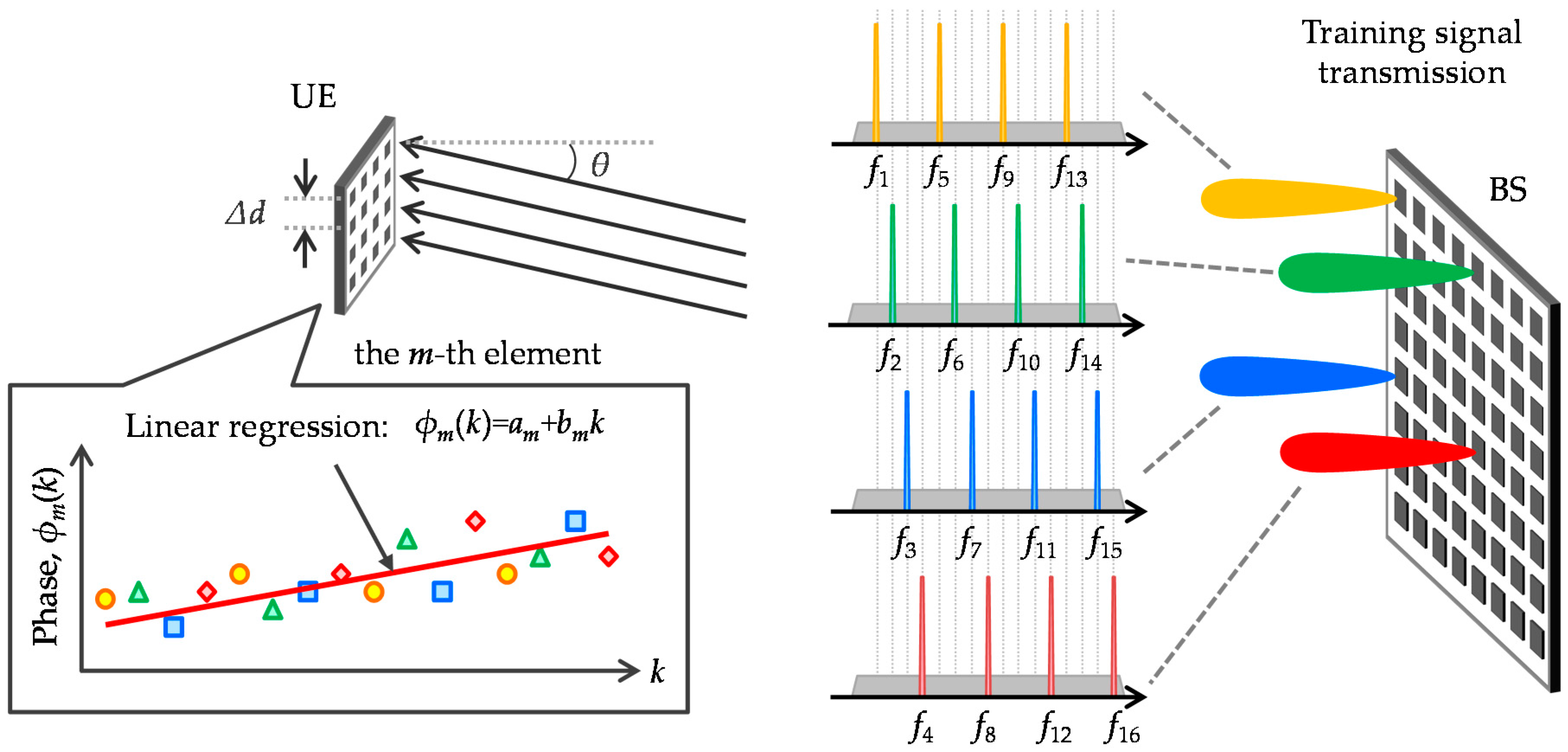
3. Simplified Beamforming by High Efficient CSI Estimation

As discussed in the previous section, the 1st eigenmode is mostly formed by the LoS component (NLoS components are suppressed). Two key challenges are reviewed here; CSI estimation in the short link budget situation and computation complexity for SVD, which is required for each subcarrier. This section presents a simplified beamforming scheme by approximately extracting CSI from the LoS component in order to alleviate the calculation cost as well as the additive noise effect.
The proposed scheme is illustrated in Figure 3. First, a training signal is sent by a few antenna elements and subcarriers, e.g., 16 of the 256 elements at equal intervals and four of the 2048 subcarriers per antenna element without overlap. When total transmission power is constant, power density is concentrated on the limited number of subcarriers. Signal-to-noise power ratio (SNR) for the selected subcarriers is improved by 10log10(2048/4/16) = 15.1 dB before beamforming. In addition, reducing the number of subcarriers can suppress PAPR per antenna element, which alleviates the need for input backoff (IBO) for training signal transmission. Second, each UE antenna element receives the training signals as if they had been transmitted from a single antenna element. UE then obtains CSI for received subcarriers using known training sequence and then calculates relative CSI, which represents the relationship of the CSI between the reference antenna element and the CSI of the other ones. Next, the phase component of the relative CSI is extracted. Third, phase information for null subcarriers is interpolated by linear regression. Let c, λ, fc (=c/λ), fs and dm be the light speed, wavelength, carrier frequency, subcarrier spacing, and distance between the m-th UE antenna element and the BS, respectively; relative phase component of LoS channel at the k-th subcarrier, exp{m(k)}, is expressed as,
e j ϕ m ( k ) = e j 2 π f c + k f s c ( d m d 1 ) = e j 2 π f c c Δ d e j 2 π k f s c Δ d
where Δd = dmd1. Here, phase fluctuation in the frequency domain is due to the term exp{−j2π(kfs/c)Δd}. In millimeter wave communication, inter-element space becomes much smaller than BS-UE distance so the relative phase information can be expressed as an array factor. Assuming a linear array with half wavelength spacing, Δd = (λ/2)(m − 1)sinθ where θ is AoA. From this we can derive:
e j ϕ m ( k ) = e j 2 π 1 2 ( m 1 ) sin θ e j 2 π k f s c λ 2 ( m 1 ) sin θ = e j π ( m 1 ) sin θ e j π k f s B B f c ( m 1 ) sin θ
where B is the channel bandwidth. It is obvious that −1/2 ≤ (kfs/B) ≤ 1/2. When the system parameters are set to fc = 20 GHz and B = 400 MHz, fraction bandwidth, B/fc, is 0.02. We consider that m = 16 and θ = 45° at the limit, so in-band phase fluctuation is around 10% of 360°. Since this condition can be satisfied, linear regression can precisely extract the LoS component using extremely reduced training subcarriers. Relationship between ϕm(k) and k can be described as:
ϕ m ( k ) = a m + b m k
am and bm can be obtained by the well-known least squares method (LSM) as follows:
[ a m b m ] = ( X H X ) 1 X H Y
where
X = [ 1 1 k 1 ] ,    Y = [ ϕ m ( k ) ]
k’ represents the subcarrier indices used for the training signal. Above operation is performed through the m-th element. Fourth, reception weight vector for the i-th UE is obtained as Ui = ϕi = [ϕ1(k),...,ϕNu(k)]T. Assuming time division duplex (TDD), UE should calibrate CSI for transmission beamforming since uplink and downlink signals go through different circuits, e.g., HPA and low noise amplifier (LNA). CSI for transmission can be obtained by applying a reciprocity calibration coefficient [29,30]. Last, UE transmits training signal via beamforming and BS estimates CSIT to calculate MU-MIMO precoding weight. Here, BS can use an existing CSI estimation scheme since the link budget is improved by the beamforming gain at the UE side. As a result, BS can obtain effective MIMO channel matrix, H’, as shown in Equation (14). If necessary, the highly efficient CSI estimation shown in Figure 3 can also be applied to the uplink where each UE uses different subcarrier/antenna combination without overlap.
Table 1 summarizes the computation complexities defined as the required number of complex multiplications. Complexity of the proposed scheme is derived from Equation (19), where Nc and Np indicate the subcarrier number for signal transmission and for training signal transmission in the proposed scheme, respectively. That of SVD is based on QR-decomposition and Householder reflections [31].

4. Results and Discussion

4.1. System Level Simulation

Principal simulation parameters are listed in Table 2. BS and UEs use UPAs with 256 and 16 elements, respectively. BS height is assumed to be 30 m and UEs with 1.5 m height are uniformly distributed in the single cell with radius of 20 m, as shown in Figure 1. SNR, given for the antenna elements linking BS and UE, is assumed to be 10 dB. Assuming a Rician fading channel with K = 10 dB, the multipath component is modeled as 11 path exponential decay with 3 dB attenuation for each 10 ns as per [32]. Spatial correlation, i.e., Rtx,i, Rrx,i, and LoS channel, change with UE rotation on the horizontal plane. CSI is updated every 1.3 ms. This corresponds to 200 symbols, each with 6.67 μs symbol duration. CSI estimation error due to the receiver noise is excluded in order to evaluate the impact of the outdated CSI. We compare the following three schemes:
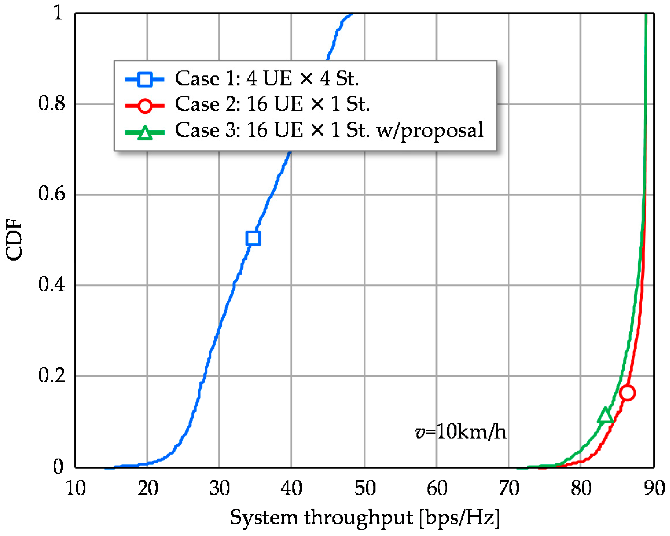
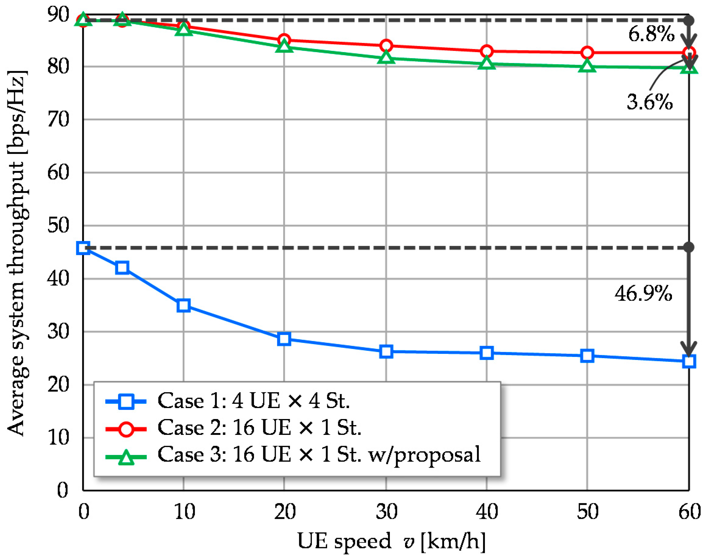
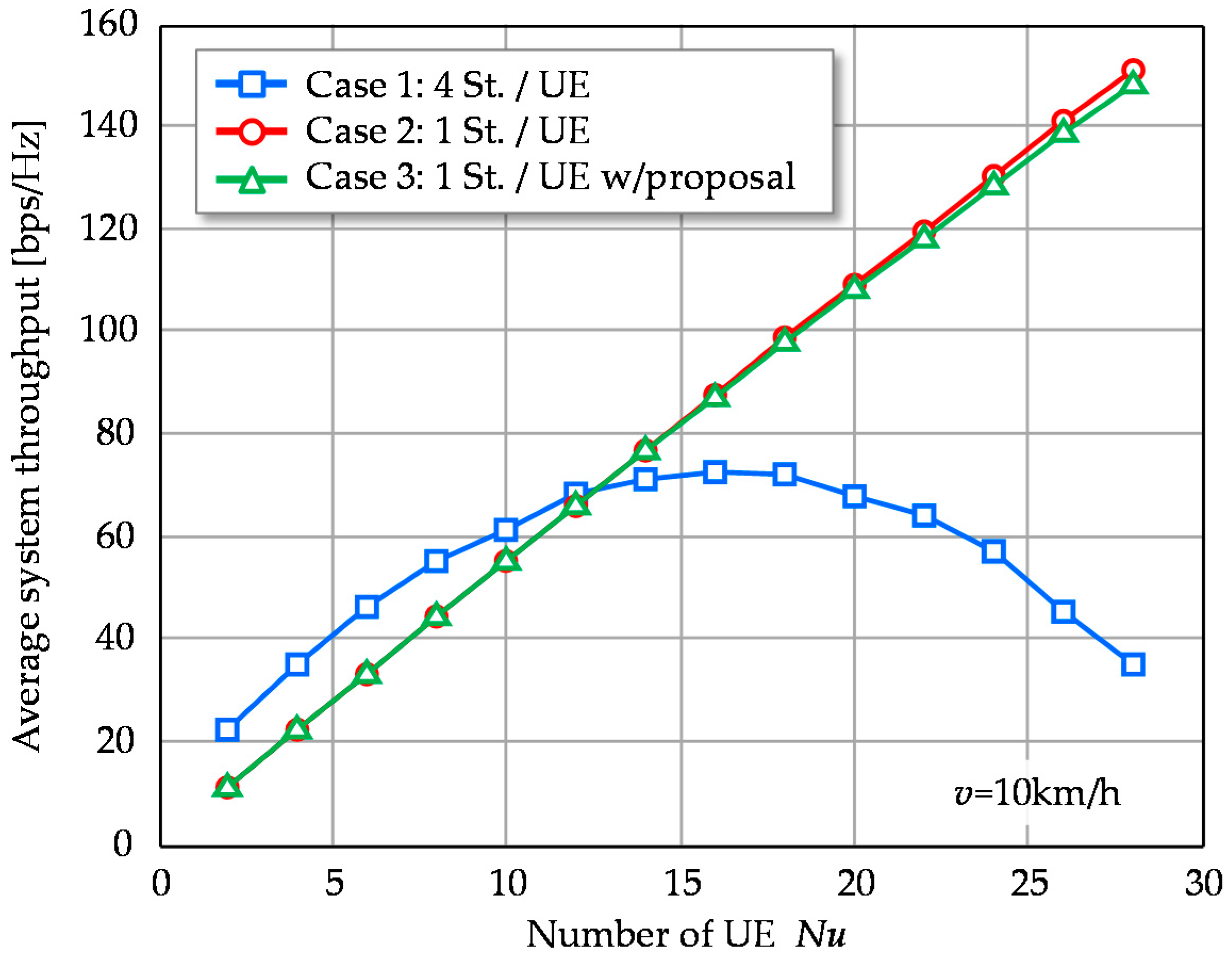
  • Case 1: Four stream per UE via BD;
  • Case 2: One stream per UE via BD (1st Eigenmode); and
  • Case 3: One stream per UE via simplified beamforming (proposal).
In Case 1, UE is assumed to perform minimum mean square error (MMSE) detection at every symbol reception. Cases 2 and 3 simply steer the beam to the BS array by using CSI at the update instance. We evaluate achievable signal-to-interference plus noise power ratio (SINR) and throughput performance. Throughput is determined based on modulation coding scheme (MCS) matches as the received SINR [33,34]. The relationship is defined in Table 3. Since the original relationship was defined for an additive white Gaussian noise (AWGN) channel, we added a margin of 6 dB to ensure a conservative evaluation. User scheduling effect is taken into account by separating the UEs by least 3 m.

4.2. Simulation Results

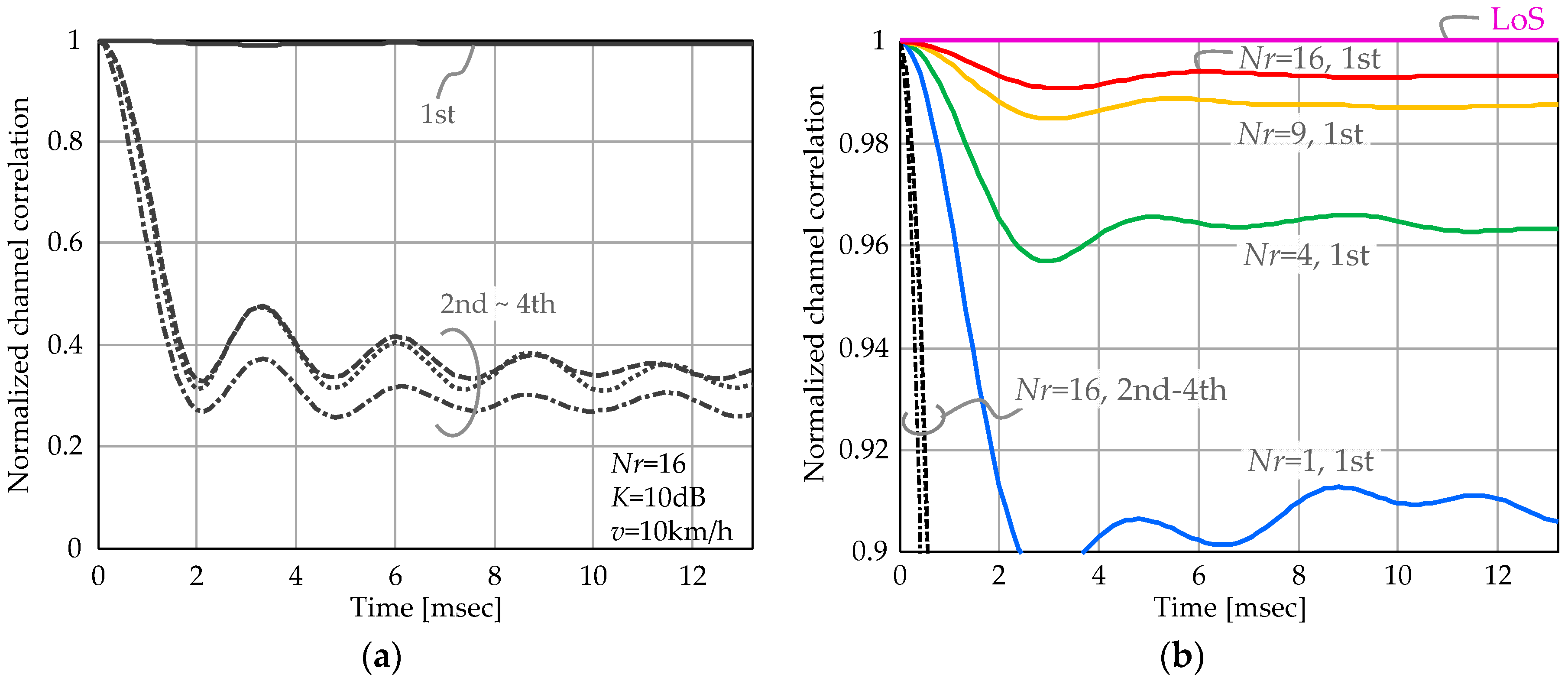
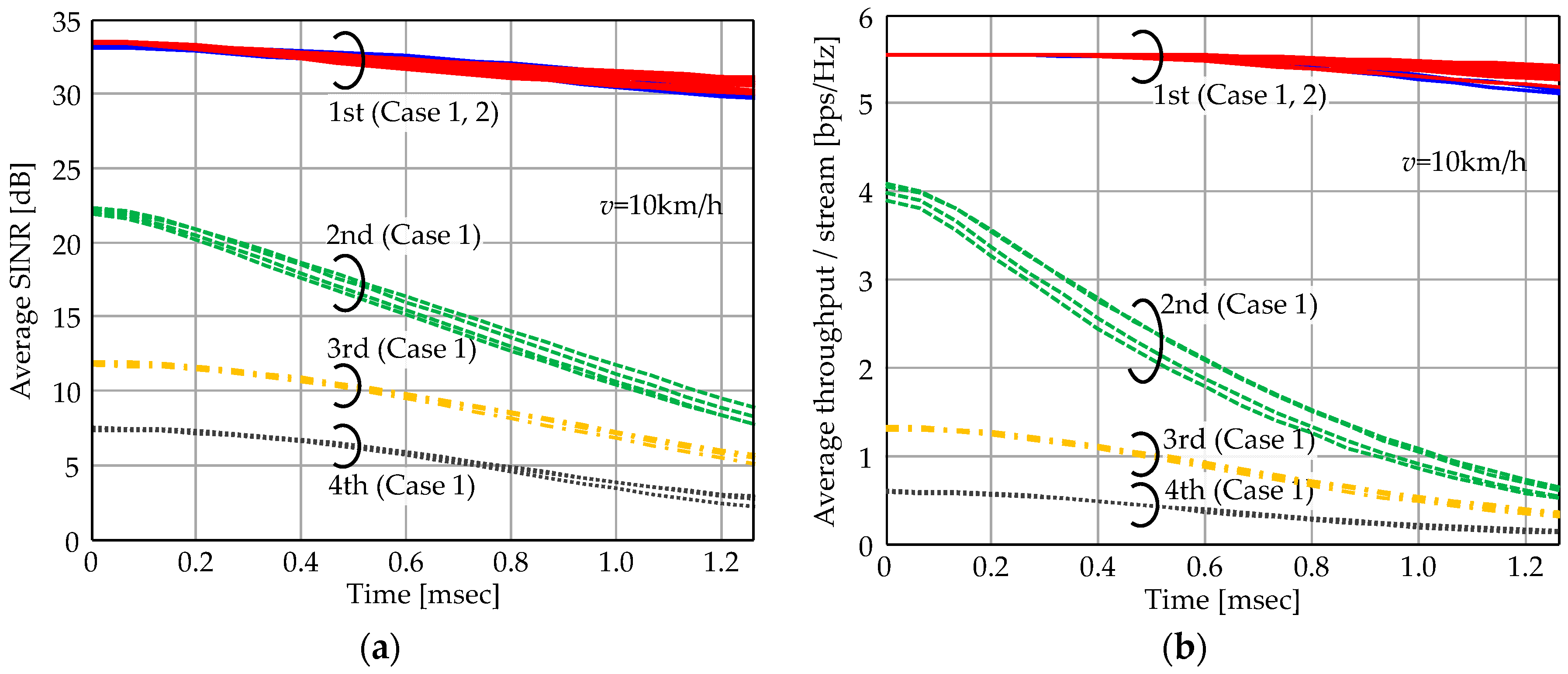
4.2.1. Performance of First Eigenmode Transmission

First we observe time variant characteristics within the CSI estimation period. Figure 4a shows average SINR fluctuation of each stream and corresponding throughput performance is shown in Figure 4b. The average values plotted include all subcarriers with various UE distributions. Here we compare Cases 1 and 2. Total transmission stream is set to NuNs = 16; 4 UEs with four streams for Case 1 and 16 UEs with single stream for Case 2. Maximum beamforming gain is calculated as 10log10{NtNr/(NuNs)} = 10log10(256 × 16/16) = 24 dB and the 1st eigenmode properly yields these gain values in Cases 1 and 2. However, higher eigenmodes for Case 1 exhibit lower SINR than the 1st one and they rapidly decrease as time progresses. Their achievable throughput values are lower than 1 bps/Hz at t = 1.3 ms. As Case 2 allocates a single stream per UE, SINR values of all signal streams remain high so the throughput degradation is minimal.
Note the achievable throughput values are directly converted from SINR in the evaluation. Practical MCS need to be determined with some margin considering the unpredictable SINR degradation possible with the time varying channel. If appropriate MCS cannot be selected, expected throughput cannot be achievable. The 1st eigenmode approach can suppress such MCS selection error since it realizes stable SINR performance. Therefore, the superiority of the 1st eigenmode transmission of Case 2 is expected to be demonstrated more clearly in actual use.

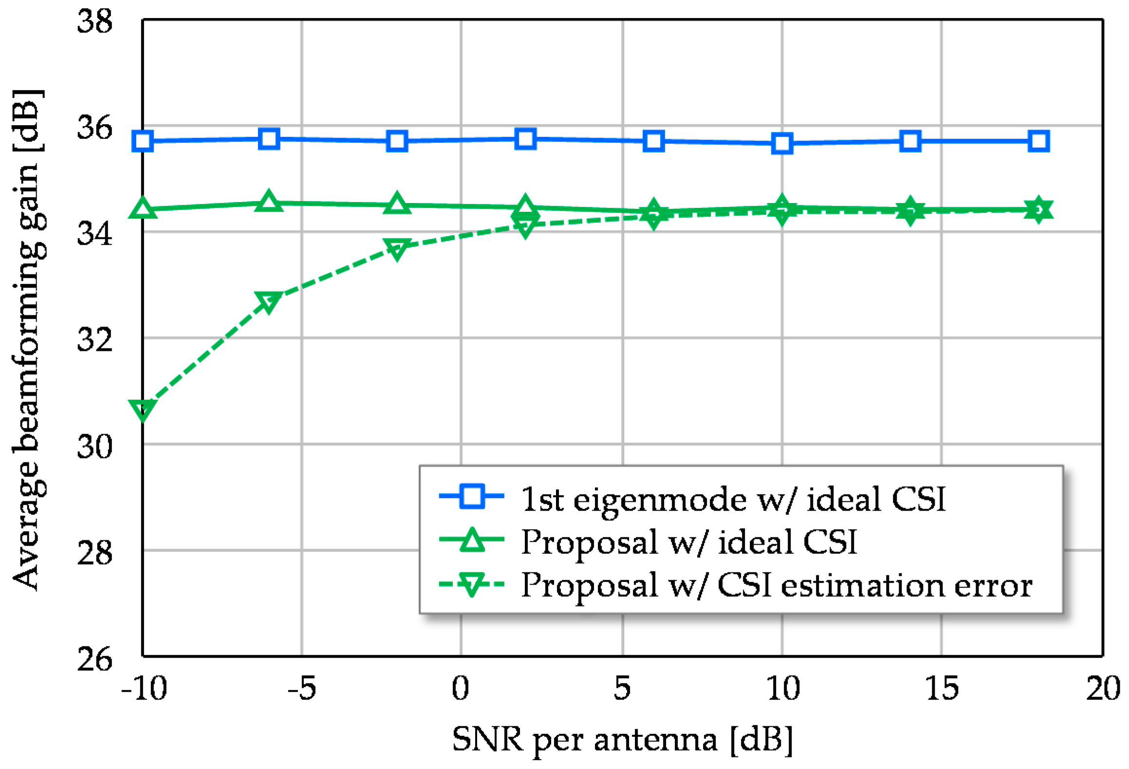
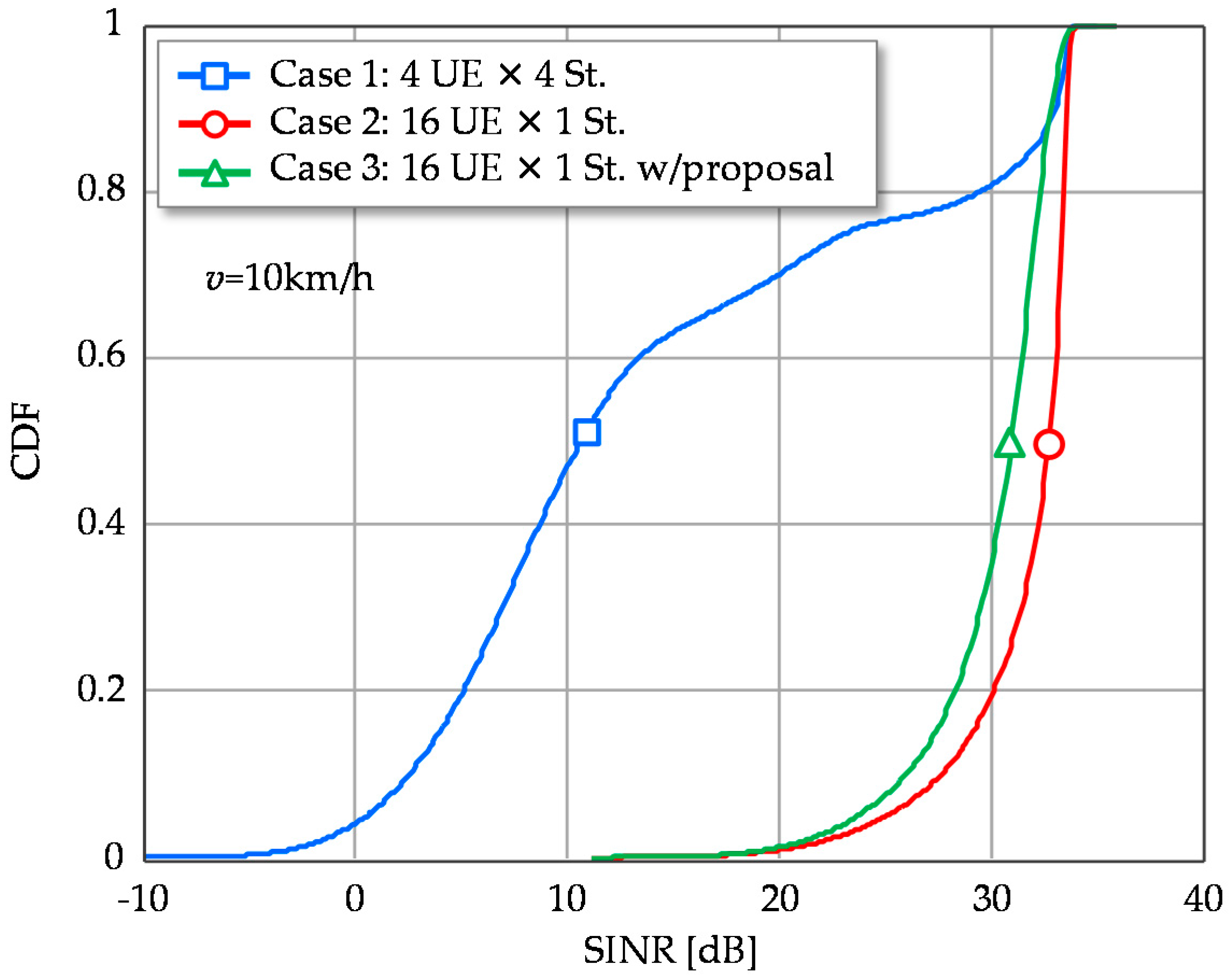
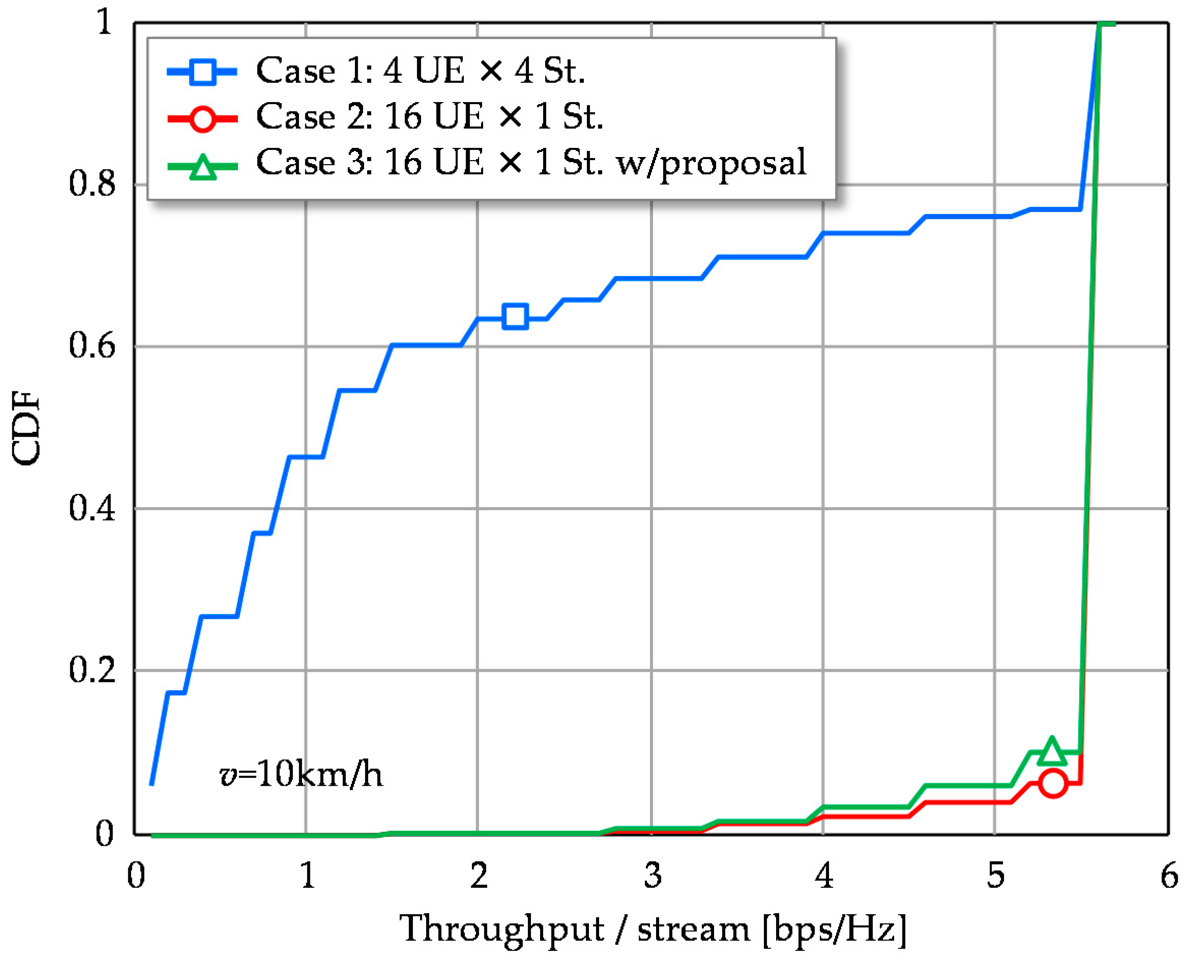
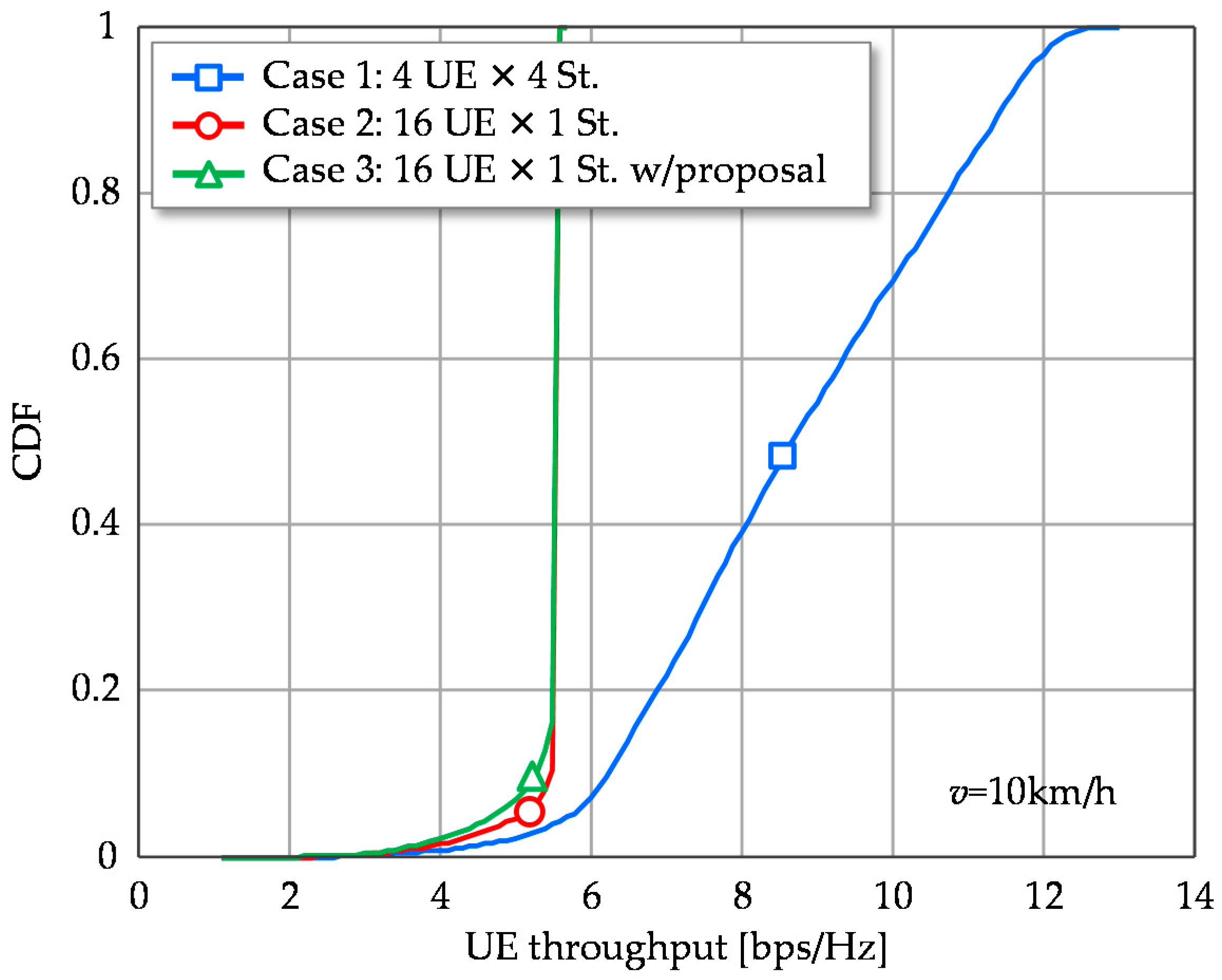
4.2.2. Performance of Simplified Beamforming

The following examines the proposed beamforming scheme in Case 3. Figure 5 shows the cumulative distribution functions (CDFs) of SINR per stream in a CSI estimation period. Case 2 exhibits high stable SINR distribution compared to Case 1 as its 2nd, 3rd and 4th eigenmodes cause relatively low SINR. The proposed scheme of Case 3 can match the SINR performance of Case 2. Though the proposed scheme is based on the simplified approximate approach of 1st eigenmode transmission, its degradation at CDF = 50% is only about 3 dB. It is still superior to Case 1 and achieves large SINR, more than 25 dB with 90% probability, where maximum MCS is available. Therefore, the 3 dB SINR degradation of the proposed scheme is negligible in terms of throughput, as shown in Figure 6. Throughput performance of multistream transmission (Case 1) is largely degraded due to the instability of the higher eigenmodes.
Figure 7 shows the CDFs of UE throughput. Case 1, with multistream transmission, outperforms the other single stream transmission schemes. Though it potentially deserves to provide a higher transmission rate per UE, it sacrifices system throughput and is strongly impacted by the channel time variation.
Figure 8 shows the CDFs of system throughput performance. As shown, Cases 2 and 3 provide quite large system throughput compared to Case 1. Under the constraint of total transmission stream number, multiplexing a large number of UEs to use a single stable stream is effective from the system throughput viewpoint.
Figure 9 plots the average system throughput versus UE speed, v. With Case 1, system throughput is decreased as movement speed increases and is reduced by 46.9% at 60 km/h. The reductions observed in Cases 2 and 3 are 6.8% and 10.4%, respectively. The gap between them is only 3.6%. Multiuser MIMO with 1st eigenmode transmission as well as our proposal can handle such high mobility situations, the movement speed is expected to be around 10 km/h considering the small cell use cases. It should be noted that extending the CSI feedback period M times corresponds to increasing the UE speed M times. Therefore, this evaluation is useful in understanding the impact of long CSI feedback periods from the viewpoint of control overhead savings.
Finally, average system throughput in terms of multiplexed UE number, Nu, is evaluated and the result is shown in Figure 10. Case 1 achieves its peak system throughput at Nu = 16. In addition, Case 1 provides higher system throughput than Cases 2 and 3 at Nu < 12. This is because the total number of signal streams for Case 1 is four times those of Cases 2 and 3 under the same spatially multiplexed UE number. However, it devours the DoF resources and results in inefficient UE throughput. The system throughput finally decreases as Nu increases further. Meanwhile, the system throughput of Cases 2 and 3 linearly increases with Nu in the plotted region and they outperform Case 1 when Nu > 14. There remain enough DoF resources with single stream transmission per UE and all UEs exploit the 1st eigenmode, which provides the highest gain. Since UEs are spatially de-correlated, 1st eigenmodes can keep their high gain and thus higher spectral efficiency is achieved even in large number of Nu.
Above results prove that exploiting the 1st eigenmode can realize stable multiuser MIMO transmission in time varying channels. System throughput can be significantly enhanced by spatially multiplexing a large number of UEs. Furthermore, we have confirmed the effectiveness of the proposed beamforming scheme based on simplified and high efficient CSI estimation. From the complexity estimate in Table 1 and the parameters used in Table 2, the conventional SVD and the proposed scheme require 278,528,000 and 20,480,000 multiplications, respectively; thus a 92.6% complexity reduction can be achieved. To emphasize this advantage, we examine the compressed sensing based CSI estimation scheme in [18], referred as multi-grid orthogonal matching pursuit (MG-OMP). When L, NTBeam, NRBeam, and (G0,G1) be the number of scatters, transmission/reception training beams, and discrete angle sets, respectively, its complexity is estimated to be O(LNTBeamNRBeam(G02 + G12)), i.e., 37,365,760 if we set L = 10, NTBeam = NRBeam = 32, (G0,G1) = (60,7) as the derived parameters. The proposed scheme offers a 45.2% reduction in complexity. However, it should be understood that our proposal can ease hardware implementation since it does only require multiplications with matrices and a vector with simplified algorithms. This is one of the remarkable advantages of our proposal.

4.3. Discussion

The above simulations assumed a fixed SNR (=10 dB) situation to permit a comprehensive evaluation. When we assume a total transmission power of 10 dBm, 0 dBi antenna gain, −174 dBm/Hz noise density and free space propagation, average reception SNR in the SISO case is about 9 dB in the simulation environment. Of course, the actual value depends on system parameters and deployment environment and the received signal strength significantly impacts the capability of the proposed CSI estimation scheme. To discuss the application region, Figure 11 plots average beamforming gain versus SNR where 1st eigenmode transmission is compared to the proposed scheme. It additionally plots the result of the proposed scheme with CSI estimation error due to additive noise. Under the total transmission power constraint, reducing the training subcarriers from 2048 to four strengthens the transmission power density per subcarrier, per antenna element, by 10log10(2048/4/16) = 15.1 dB. In addition, thinning out the training subcarriers also reduces PAPR and thus the transmission power can be raised thanks to easing IBO; this reduction is assumed to be 6 dB or so [35]. As seen by the results, even with CSI estimation error, the proposed scheme retains comparable beamforming gain to the ideal CSI case in the low SNR region around 0 dB. Though the practical gain 15.1 + 6 = 21.1 dB is much smaller than the beamforming gain 36 dB, the lack of the gain does not cause serious degradation on our proposed scheme, even in low SNR region. This validates the throughput performance evaluations in Section 4.2, which assumed ideal CSI.
As a result, our proposal can eliminate the link budget shortfall for CSI estimation in the millimeter waveband. It should be noted that assuming OFDM, timing extraction for fast Fourier transform (FFT) windowing for the CSI estimation on the reduced subcarrier is a critical issue since it is performed in the time domain, i.e., the gain provided by the reduced number of training subcarriers cannot be obtained. Meanwhile, millimeter wave small cells can be supported by control signaling from macro cell using micro wave band [36]. It will be possible to know the FFT windowing timing by synchronizing the macro cell system.

5. Conclusions

This paper verified the effectiveness of 1st eigenmode transmission in multiuser massive MIMO assuming LoS dominant channels in the millimeter wave band. Because of the 1st eigenmode’s robustness and high-gain property, quite a large number of UEs can be spatially multiplexed; it is effective in enhancing the system throughput rather than UE throughput. Additionally, we proposed simplified beamforming with highly efficient CSI estimation in order to ease heavy computation complexity imposed by 1st eigenmode transmission. It can also suppress the additive noise effect and thus improve CSI estimation accuracy. Our approximate approach achieved performance comparable to that of rigorously applied 1st eigenmode transmission.

Acknowledgments

The authors are sincerely grateful to Masashi Nakatsugawa and Hiroyuki Nakamura of NTT Access Network Service Systems Laboratories for their constant encouragement.

Author Contributions

K.M. conducted computer simulations and wrote the paper; T.I. contributed simulation tools; A.O. designed the system model and the proposed scheme; T.A. verified the proposed scheme; Y.S. and S.K. contributed to the analysis of the results; and M.I. coordinated and supervised the work.

Conflicts of Interest

The authors declare no conflict of interest.

References

  1. Bangerter, B.; Talwar, S.; Arefi, R.; Stewart, K. Networks and devices for the 5G era. IEEE Commun. Mag. 2014, 52, 90–96. [Google Scholar] [CrossRef]
  2. Suyama, S.; Shen, J.; Benjebbour, A.; Kishiyama, Y.; Okumura, Y. Super high bit rate radio access technologies for small cells using higher frequency bands. In Proceedings of the IEEE MTT International Microwave Symposium (IMS), Tampa Bay, FL, USA, 1–6 June 2014.
  3. Nakamura, T.; Benjebbour, A.; Kishiyama, Y.; Suyama, S.; Imai, T. 5G radio access: Requirements, concept and experimental trials. IEICE Trans. Commun. 2015, 98, 1397–1406. [Google Scholar] [CrossRef]
  4. Marzetta, T.L. Noncooperative cellular wireless with unlimited numbers of base station antennas. IEEE Trans. Wirel. Commun. 2010, 9, 3590–3600. [Google Scholar] [CrossRef]
  5. Hoydis, J.; Brink, S.T.; Debbah, M. Massive MIMO in the UL/DL of cellular networks: How many antennas do we need? IEEE J. Sel. Areas Commun. 2013, 31, 160–171. [Google Scholar] [CrossRef] [Green Version]
  6. Rusek, F.; Persson, D.; Lau, B.K.; Larsson, E.G.; Marzetta, T.L.; Edfors, O.; Tufvesson, F. Scaling up MIMO: Opportunities and challenges with very large arrays. IEEE Signal Process. Mag. 2013, 30, 40–60. [Google Scholar] [CrossRef]
  7. Larsson, E.G.; Edfors, O.; Tufvesson, F.; Marzetta, T.L. Massive MIMO for next generation wireless systems. IEEE Commun. Mag. 2014, 52, 186–195. [Google Scholar] [CrossRef]
  8. Obara, T.; Suyama, S.; Shen, J.; Okumura, Y. Joint fixed beamforming and eigenmode precoding for super high bit rate massive MIMO systems using higher frequency bands. In Proceedings of the IEEE 25th Personal, Indoor and Mobile Radio Communications (PIMRC), Washington, DC, USA, 2–5 September 2014.
  9. Spencer, Q.H.; Peel, C.B.; Swindlehurst, A.L.; Haardt, M. An introduction to the multi-user MIMO downlink. IEEE Commun. Mag. 2004, 42, 60–67. [Google Scholar] [CrossRef]
  10. Taira, A.; Iura, H.; Nakagawa, K.; Uchida, S.; Ishioka, K.; Okazaki, A.; Okamura, A.; Suyama, S.; Okumura, Y. Evaluation of multi-beam multiplexing technologies for massive MIMO system based on the EHF-band channel measurement. In Proceedings of the 21st Asia-Pacific Conference on Communications (APCC), Kyoto, Japan, 14–16 October 2015.
  11. Ogawa, Y.; Yamaguchi, K.; Bui, H.P.; Nishimura, T.; Ohgane, T. Behavior of a multi-user MIMO system in time-varying environments. IEICE Trans. Commun. 2013, 96, 2364–2371. [Google Scholar] [CrossRef]
  12. Iwakuni, T.; Maruta, K.; Ohta, A.; Shirato, Y.; Kurosaki, S.; Arai, T.; Iizuka, M. Massive MIMO effect for multiuser spatial multiplexing in time varying channel. IEICE Commun. Express 2015, 4, 270–275. [Google Scholar] [CrossRef]
  13. Jose, J.; Ashikhmin, A.; Marzetta, T.; Vishwanath, S. Pilot contamination and precoding in multi-cell TDD systems. IEEE Trans. Wirel. Commun. 2011, 10, 2640–2651. [Google Scholar] [CrossRef]
  14. Schmidt, R. Multiple emitter location and signal parameter estimation. IEEE Trans. Antennas Propag. 1986, 34, 276–280. [Google Scholar] [CrossRef]
  15. Roy, R.; Kailath, T. ESPRIT-estimation of signal parameters via rotational invariance techniques. IEEE Trans. Acoust. Speech Signal Process. 1989, 37, 984–995. [Google Scholar] [CrossRef]
  16. Tsang, Y.; Poon, A.; Addepalli, S. Coding the beams: Improving beamforming training in mmwave communication system. In Proceedings of the IEEE Global Communications Conference (GLOBECOM), Houston, TX, USA, 5–9 December 2011.
  17. Alkhateeb, A.; Ayach, O.E.; Leus, G.; Heath, R.W. Channel estimation and hybrid precoding for millimeter wave cellular systems. IEEE J. Sel. Top. Signal Process. 2014, 8, 831–846. [Google Scholar] [CrossRef]
  18. Lee, J.; Gil, G.T.; Lee, Y.H. Exploiting spatial sparsity for estimating channels of hybrid MIMO systems in millimeter wave communications. In Proceedings of the IEEE Global Communications Conference (GLOBECOM), Austin, TX, USA, 8–12 December 2014.
  19. Giordani, M.; Mezzavilla, M.; Barati, C.N.; Rangan, S.; Zorzi, M. Comparative analysis of initial access techniques in 5G mmWave cellular networks. In Proceedings of the 50th Annual Conference on Information Science and Systems (CISS), Princeton, NJ, USA, 16–18 March 2016.
  20. Tsai, P.Y.; Chiueh, T.D. Frequency-domain interpolation-based channel estimation in pilot-aided OFDM systems. In Proceedings of the IEEE 59th Vehicular Technology Conference (VTC 2004-Spring), Milan, Italy, 17–19 May 2004.
  21. Seo, J.W.; Wee, J.W.; Jeon, W.G.; Paik, J.H.; Kim, D.K. An enhanced DFT-based channel estimation using virtual interpolation with guard bands prediction for OFDM. In Proceedings of the IEEE 17th International Symposium on Personal, Indoor and Mobile Radio Communications (PIMRC), Helsinki, Finland, 11–14 September 2006.
  22. Peter, M.; Wisotzki, M.; Raceala-Motoc, M.; Keusgen, W.; Felbecker, R.; Jacob, M.; Priebe, S.; Kurner, T. Analyzing human body shadowing at 60 GHz: Systematic wideband MIMO measurements and modeling approaches. In Proceedings of the 10th European Conference on Antennas and Propagation (EuCAP), Prague, Czech Republic, 26–30 March 2012.
  23. Yu, K.; Bengtsson, M.; Ottersten, B.; McNamara, D.; Karlsson, P.; Beach, M. Modeling of wide-band MIMO radio channels based on NLoS indoor measurements. IEEE Trans. Veh. Technol. 2004, 53, 655–665. [Google Scholar] [CrossRef]
  24. Raj, J.S.K.; Prabu, A.S.; Vikram, N.; Schoebel, J. Spatial correlation and MIMO capacity of uniform rectangular dipole arrays. IEEE Antennas Wirel. Propag. Lett. 2008, 7, 97–100. [Google Scholar] [CrossRef]
  25. GPP TR 36.873 V12.2.0. Study on 3D Channel Model for LTE (Release 12). June 2015. Available online: http://www.3gpp.org/dynareport/36873.htm (accessed on 24 June 2016).
  26. Cramer, R.J.M.; Scholtz, R.A.; Win, M.Z. Evaluation of an ultra-wide-band propagation channel. IEEE Trans. Antennas Propag. 2002, 50, 561–570. [Google Scholar] [CrossRef]
  27. Jakes, W.C. Microwave Mobile Communications, 2nd ed.; Wiley-IEEE Press: Hoboken, NJ, USA, 1994; pp. 8–78. [Google Scholar]
  28. Spencer, Q.H.; Swindlehurst, A.L.; Haardt, M. Zero-forcing methods for downlink spatial multiplexing in multiuser MIMO channels. IEEE Trans. Signal Process. 2004, 52, 461–471. [Google Scholar] [CrossRef]
  29. Nishimori, K.; Cho, K.; Takatori, Y.; Hori, T. Automatic calibration method using transmitting signals of an adaptive array for TDD systems. IEEE Trans. Veh. Technol. 2001, 50, 1636–1640. [Google Scholar] [CrossRef]
  30. Fukuzono, H.; Murakami, T.; Kudo, R.; Takatori, Y.; Mizoguchi, M. Weighted-combining calibration on multiuser MIMO systems with implicit feedback. IEICE Trans. Commun. 2015, 98, 701–713. [Google Scholar] [CrossRef]
  31. Trefethen, L.N.; Bau, D., III. Numerical Linear Algebra, 1st ed.; Society for Industrial and Applied Mathematics: Philadelphia, PA, USA, 1997. [Google Scholar]
  32. Deng, S.; Samimi, M.K.; Rappaport, T.S. 28 GHz and 73 GHz millimeter-wave indoor propagation measurements and path loss models. In Proceedings of the IEEE International Conference on Communications (ICC), London, UK, 8–12 June 2015.
  33. 3GPP TS 36.213. Evolved Universal Terrestrial Radio Access (E-UTRA); Physical Layer Procedures (Release 10). June 2011. Available online: http://www.3gpp.org/dynareport/36213.htm (accessed on 25 April 2016).
  34. Mehlführer, C.; Wrulich, M.; Ikuno, J.C.; Bosanska, D.; Rupp, M. Simulating the long term evolution physical layer. In Proceedings of the 17th European Signal Processing Conference (EUSIPCO), Glasgow, UK, 24–28 August 2009.
  35. Prasad, R. OFDM for Wireless Communications Systems, 1st ed.; Artech House: Norwood, MA, USA, 2004. [Google Scholar]
  36. Peng, H.; Yamamoto, T.; Suegara, Y. Extended user/control plane architectures for tightly coupled LTE/WiGig interworking in millimeter-wave heterogeneous networks. In Proceedings of the IEEE Wireless Communications and Networking Conference (WCNC), New Orleans, LA, USA, 9–12 March 2015.
Figure 1. System model: (a) Multistream transmission per user equipment (UE): Nu = 4 and Ns = 4; and (b) 1st eigenmode transmission per UE: Nu = 16 and Ns = 1.
Sensors 16 01051 g001
Figure 2. Channel time variation: (a) channel correlation fluctuation of four eigenmodes when Nr = 16; and (b) channel correlation of the 1st eigenmode with increased number of UE antenna elements, Nr.
Sensors 16 01051 g002
Figure 3. Proposed high efficient channel state information (CSI) estimation.
Sensors 16 01051 g003
Figure 4. Time variant characteristics within the CSI estimation period. Case 1: Nu = 4, Ns = 4; Case 2: Nu = 16, Ns = 1. (a) Average SINR per stream versus elapsed time. (b) Average throughput per stream versus elapsed time.
Sensors 16 01051 g004
Figure 5. Cumulative distribution functions (CDFs) of SINR per signal stream.
Sensors 16 01051 g005
Figure 6. CDFs of throughput per signal stream.
Sensors 16 01051 g006
Figure 7. CDFs of UE throughput.
Sensors 16 01051 g007
Figure 8. CDFs of System throughput.
Sensors 16 01051 g008
Figure 9. Average system throughput versus UE speed.
Sensors 16 01051 g009
Figure 10. Average system throughput versus number of multiplexed UEs.
Sensors 16 01051 g010
Figure 11. Average beamforming gain versus signal-to-noise power ratio (SNR).
Sensors 16 01051 g011
Table 1. Computation complexity.
Precoding SchemeComplexity
Proposed scheme10NcNpNr
SVD2Nc(NtNr2 + Nr3)
Table 2. Simulation parameters.
ParametersValues
Carrier frequency20 GHz
Bandwidth400 MHz
Number of FFT points2048
Number of subcarriers; Nc2000
Number of subcarriers for proposed CSI estimation; Np64 (4 subcarriers × 16 antennas)
Number of BS antennas; Nt256 (16 × 16) UPA, 0.5λ spacing, HPBW = 65°
Number of UE antennas; Nr16 (4 × 4) UPA, 0.5λ spacing, HPBW = 65°
Number of UEs; NuCase 1: 4; Cases 2, 3: 16
Tx streams per UE; NsCase 1: 4; Cases 2, 3: 1
SNR10 dB @ SISO
Channel modelRician fading, K = 10 dB
11 path exponential decay
RMS delay spread: 14 ns
Tx/Rx Angular spread5°/5°
PrecodingBD/Eigenmode transmission
PostcodingMMSE
Symbol duration6.67 μs
CSI estimation period1.334 ms (200 symbol)
UE speed; v10 km/h (fDTS = 1.2 × 10⁻³)
Table 3. Achievable throughput for signal-to-interference plus noise power ratio (SINR).
MCS IndexSINR (dB)Throughput (bps/Hz)
0-0
11.000.1523
23.210.2344
35.430.3770
46.360.6016
58.140.8770
69.931.1758
711.711.4766
813.501.9141
915.292.4063
1017.072.7305
1118.863.3223
1220.643.9023
1322.434.5234
1424.215.1152
1526.005.5547

