
Giant Magnetoresistance: Basic Concepts, Microstructure, Magnetic Interactions and Applications

Abstract
:1. Introduction
2. Theory
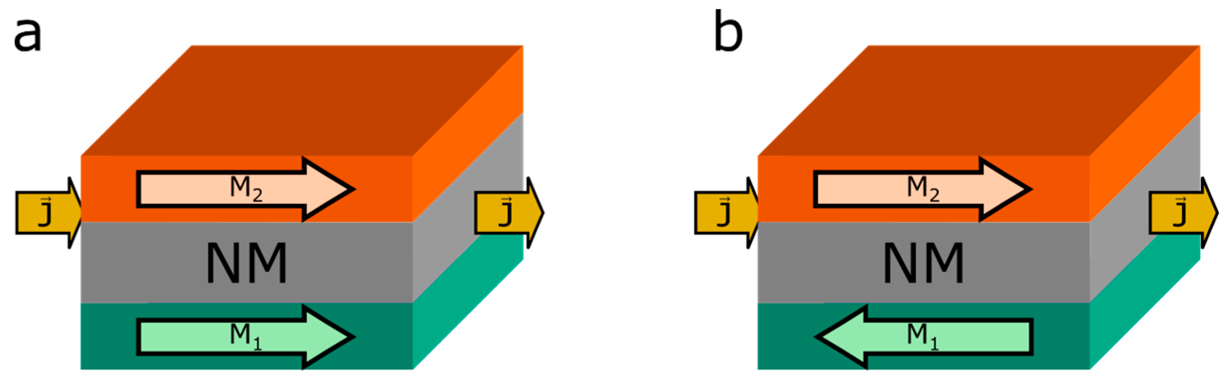
2.1. Giant Magnetoresistance in Magnetic Multilayered Systems
- (a)
- increases with increasing specular scattering at the outer boundaries as long as the scattering at the interfaces is not completely specular for both spin channels.
- (b)
- is in general small as long as the type of scattering at interfaces for both spin channels is equal .
- (c)
- dependence on the thickness of the magnetic layers is in general dependent on the scattering parameters, but its asymptotic value as function of , the non-magnetic layer’s thickness is zero , as well as for .
- (d)
- increases with increasing relaxation time to a maximum and then stays constant, or slowly decreases when the difference in specular scattering chances and are high.
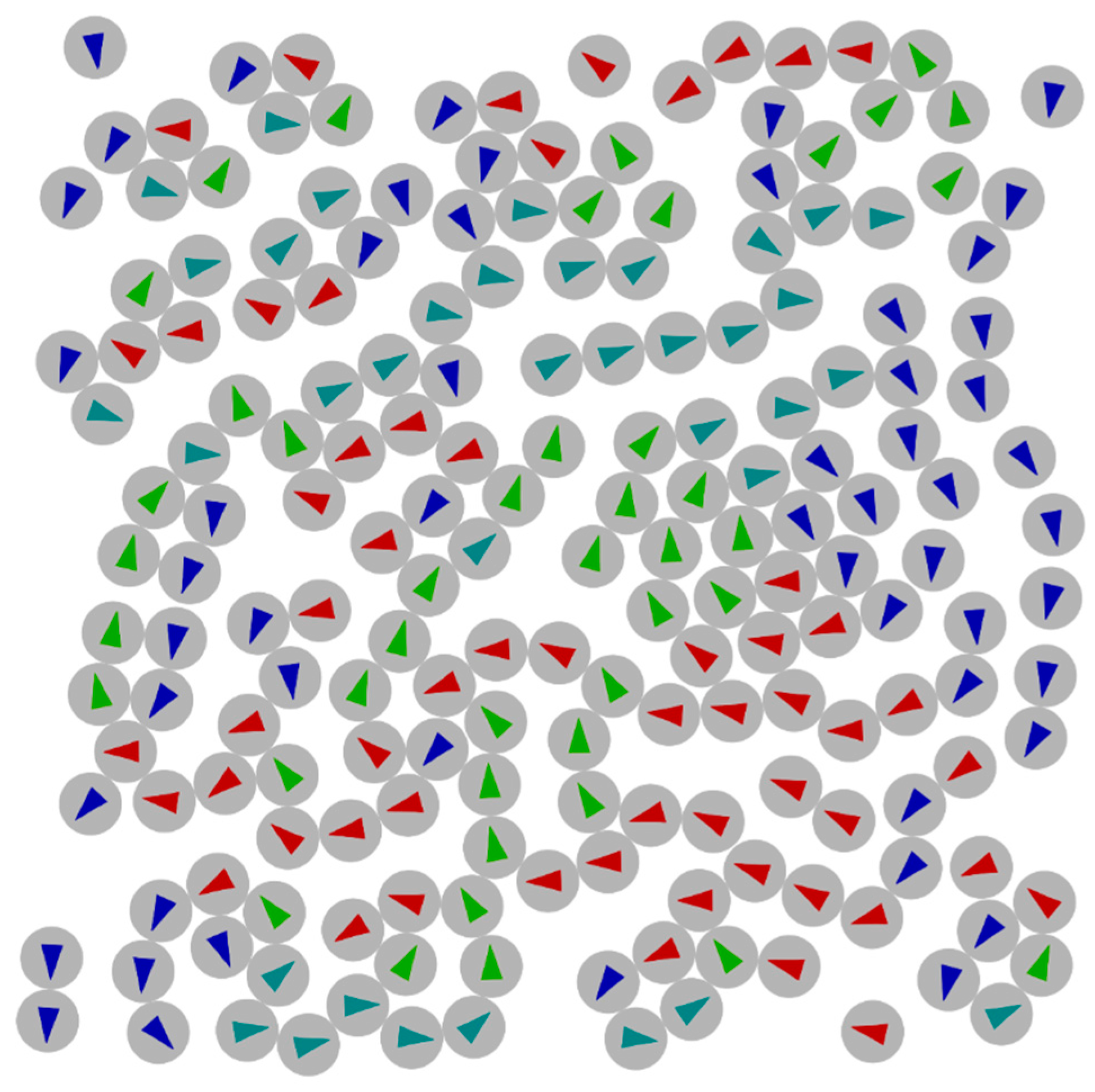
2.2. Giant Magnetoresistance in Granular Solids
- (a)
- Magnetoresistance increases with the mean free path of the electrons in the matrix material.
- (b)
- Magnetoresistance increases with the ratio between spin-dependent and spin-independent potentials, which they expect to be comparable to those found in multilayers.
- (c)
- Magnetoresistance increases with spin-dependent scattering roughness of the interfaces.
- (d)
- Magnetoresistance increases with decreasing grain size as long as the external magnetic field is strong enough to saturate all granules.
- (e)
- Magnetoresistance increases with concentration of granules as long as the granules do not form magnetic domains at high concentrations.
- (f)
- Magnetoresistance depends on the size distribution of the grains and needs to be precisely known to compare theory and experiment.
- (g)
- Magnetoresistance differs from when the grain size distribution is broad as approaches .
3. GMR Systems
3.1. Thin Film Systems
3.1.1. Information Technology
3.1.2. Automotive Applications
3.1.3. Biosensors
3.2. Granular Bulk Systems
3.3. Hybrid Structures
3.4. Nanoparticular GMR Systems
4. Conclusions
Acknowledgments
Author Contributions
Conflicts of Interest
Abbreviations
| GMR | Giant magnetoresistance |
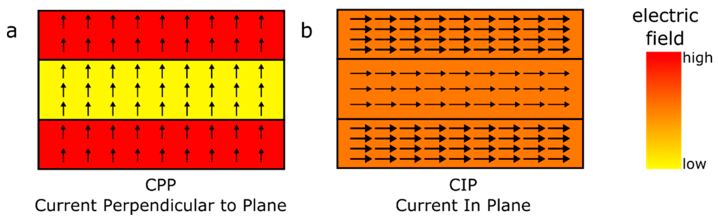
| CIP | Current in plane |
| CPP | Current perpendicular to plane |
| RKKY | Ruderman-Kittel-Kasuya-Yoshida (interaction) |
| AMR | Anisotropic magnetoresistance |
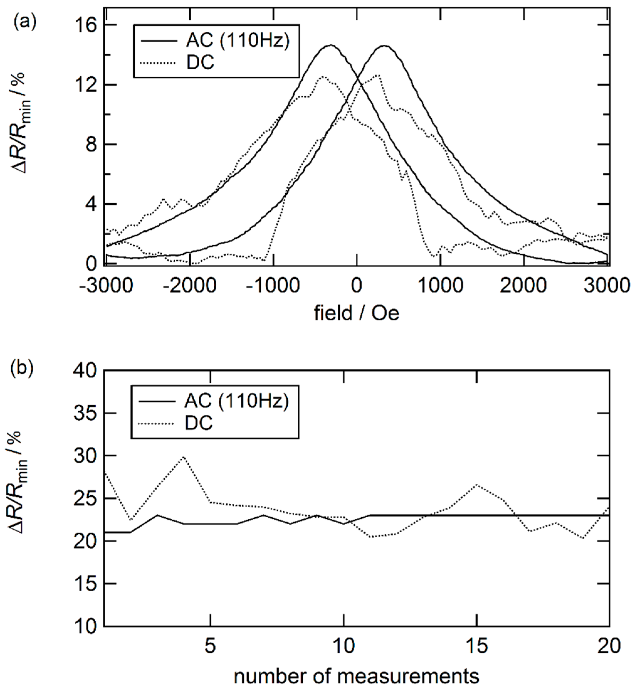
| DC | Direct current |
| AC | Alternating current |
| TEM | transmission electron microscopy |
| AFC | Antiferromagnetic coupling |
| APT | Atom probe tomography |
References
- Baibich, M.N.; Broto, J.M.; Fert, A.; van Dau, F.N.; Petro, F.; Eitenne, P.; Creuzet, G.; Friederich, A.; Chazelas, J. Giant Magnetoresistance of (001)Fe/(001)Cr Magnetic Superlattices. Phys. Rev. Lett. 1988, 61. [Google Scholar] [CrossRef] [PubMed]
- Binasch, G.; Grünberg, P.; Saurenbach, F.; Zinn, W. Enhanced magnetoresistance in layered magnetic structures with antiferromagnetic interlayer exchange. Phys. Rev. B 1989, 39, 4828–4830. [Google Scholar] [CrossRef]
- Hartmann, U. Magnetic Multilayers and Giant Magnetoresistance—Fundamentals and Industrial Applications; Springer: Verlag/Berlin, Germany, 2000. [Google Scholar]
- Examples from the Field of Industrial Sensors. Avialable online: http://sensitec.com/english/applications/industry (accessed on 29 April 2016).
- Krishna, V.D.; Wu, K.; Perez, A.M.; Wang, J.-P. Giant Magnetoresistance-based Biosensor for Detection of Influenza a Virus. Front. Microbiol. 2016, 7. [Google Scholar] [CrossRef] [PubMed]
- Tsymbal, E.Y.; Pettifor, D.G. Perspectives of giant magnetoresistance. Solid State Phys. 2001, 56, 113–237. [Google Scholar]
- Schuller, I.K.; Kim, S.; Leighton, C. Magnetic superlattices and multilayers. J. Magn. Magn. Mater. 1999, 200, 571–582. [Google Scholar] [CrossRef]
- Kubo, R. Statistical-mechanical theory of irreversible processes. I. General theory and simple applications to magnetic and conduction problems. J. Phys. Soc. Jpn. 1957, 12, 570–586. [Google Scholar] [CrossRef]
- Camblong, H.E. Linear transport theory of magnetoconductance in metallic multilayers: A real-space approach. Phys. Rev. B 1995, 51, 1855–1865. [Google Scholar] [CrossRef]
- Camblong, H.E.; Levy, P.M.; Zhang, S. Electron transport in magnetic inhomogeneous media. Phys. Rev. B 1995, 51, 16052–16072. [Google Scholar] [CrossRef]
- Levy, P.M.; Zhang, S.; Fert, A. Electrical conductivity of magnetic multilayered structures. Phys. Rev. Lett. 1990, 65, 1643–1646. [Google Scholar] [CrossRef] [PubMed]
- Gijs, M.A.M.; Bauer, G.E.W. Perpendicular giant magnetoresistance of magnetic multilayers. Adv. Phys. 1997, 46, 285–445. [Google Scholar] [CrossRef]
- Fuchs, K. The conductivity of thin metallic films according to the electron theory of metals. Math. Proc. Camb. 1938, 34, 100–108. [Google Scholar] [CrossRef]
- Sondheimer, E.H. The mean free path of electrons in metals. Adv. Phys. 1952, 1, 1–42. [Google Scholar] [CrossRef]
- Valet, T.; Fert, A. Theory of the perpendicular magnetoresistance in magnetic multilayers. Phys. Rev. B 1993, 48, 7099–7113. [Google Scholar] [CrossRef]
- Tsymbal, E.Y.; Pettifor, D.G.; Maekawa, S. Giant Magnetoresistance: Theory. In Handbook of Spin Transport and Magnetism, 1st ed.; Tsymbal, E.Y., Žutic, I., Eds.; CRC Press: Boca Raton, FL, USA, 2011; p. 98. [Google Scholar]
- Hood, R.Q.; Falicov, L.M. Boltzmann-equation approach to the negative magnetoresistance of ferromagnetic-normal-metal multilayers. Phys. Rev. B 1992, 46. [Google Scholar] [CrossRef]
- Ustinov, V.V.; Kravtsov, E.A. A unified theory of parallel and perpendicular giant magnetoresistance in metallic superlattices. J. Phys. Condens. Matter 1995, 7, 3471–3484. [Google Scholar] [CrossRef]
- Xiao, J.Q.; Jiang, J.S.; Chien, C.L. Giant magnetoresistance in nonmultilayer magnetic systems. Phys. Rev. Lett. 1992, 68, 3749–3752. [Google Scholar] [CrossRef] [PubMed]
- Kim, J.H.; Xiao, J.Q.; Chien, C.L.; Tesanovic, Z.; Xing, L. A model for giant magnetoresistance in magnetic granular solids. Solid State Commun. 1994, 89, 157–161. [Google Scholar] [CrossRef]
- Xiao, J.Q.; Jiang, J.S.; Chien, C.L. Giant magnetoresistance in the granular Co-Ag system. Phys. Rev. B 1992, 46, 9266–9269. [Google Scholar] [CrossRef]
- Xiong, P.; Xiao, G.; Wang, J.Q.; Xiao, J.Q.; Jiang, J.S.; Chien, C.L. Extraordinary Hall effect and giant magnetoresistance in the granular Co-Ag system. Phys. Rev. Lett. 1992, 69, 3220–3223. [Google Scholar] [CrossRef] [PubMed]
- Zhang, S.; Levy, P.M. Conductivity and magnetoresistance in magnetic granular films. J. Appl. Phys. 1993, 73, 5315–5319. [Google Scholar] [CrossRef]
- Zhang, S.; Levy, P.M. Conductivity perpendicular to the plane of multilayered structures. J. Appl. Phys. 1991, 69, 4786–4788. [Google Scholar] [CrossRef]
- Ferrari, E.F.; Da Silva, F.C.S.; Knobel, M. Influence of the distribution of magnetic moments on the magnetization and magnetoresistance in granular alloys. Phys. Rev. B 1997, 56. [Google Scholar] [CrossRef]
- Ferrari, E.F.; da Silva, F.C.S.; Knobel, M. Theory of giant magnetoresistance in granular alloys. Phys. Rev. B 1999, 59, 8412–8415. [Google Scholar] [CrossRef]
- Teich, L.; Kappe, D.; Rempel, T.; Meyer, J.; Schroeder, C.; Hütten, A. Modeling of Nanoparticular Magnetoresistive Systems and the Impact on Molecular Recognition. Sensors 2015, 15, 9251–9264. [Google Scholar] [CrossRef] [PubMed]
- Parkin, S.S.P. Giant Magnetoresistance in Magnetic Nanostructures. Annu. Rev. Mater. Sci. 1995, 25, 357–388. [Google Scholar] [CrossRef]
- Modak, A.R.; Smith, D.J.; Parkin, S.S.P. Dependence of giant magnetoresistance on grain size in Co/Cu multilayers. Phys. Rev. B 1994, 50, 4232–4325. [Google Scholar] [CrossRef]
- Modak, A.R.; Parkin, S.S.P.; Smith, D.J. Microstructural characterization of Co/Cu multilayers. J. Magn. Magn. Mater. 1994, 129, 415–422. [Google Scholar] [CrossRef]
- Paul, A.; Damm, T.; Bürgler, D.E.; Stein, S.; Kohlstedt, H.; Grünberg, P. Correlation of magnetotransport and structure in sputtered Co/Cu multilayers. J. Phys. Condens. Matter 2003, 15, 2471–2491. [Google Scholar] [CrossRef]
- Lenczowski, S.K.J.; Gijs, M.A.M.; Giesbers, J.B.; van der Verdonk, R.J.M.; de Jonge, W.J.M. Interpretation of the giant magnetoresistance effect in Co/Cu (100) multilayers with the quantum model of giant magnetoresistance. Phys. Rev. B 1994, 50, 9982–9988. [Google Scholar] [CrossRef]
- Heitmann, S. Cobalt/Copper Multilayers: Interplay of Microstructure and GMR and Recrystallization as the Key towards Temperature Stability. Ph.D. Thesis, University of Bielefeld, Bielefeld, Germany, 19 March 2004. [Google Scholar]
- Dieny, B.; Speriosu, V.S.; Metin, S.; Parkin, S.S.P.; Gurney, B.A.; Baumgart, P.; Wilhoit, D.R. Magnetotransport properties of magnetically soft spin-valve structures. J. Appl. Phys. 1991, 69, 4774–4779. [Google Scholar] [CrossRef]
- Nogués, J.; Schuller, I.K. Exchange bias. J. Magn. Magn. Mater. 1999, 192, 203–232. [Google Scholar] [CrossRef]
- Plumer, M.L.; van Ek, J.; Weller, D. The Physics of Ultra-High-Density Magnetic Recording; Springer: Berlin, Germany, 2001. [Google Scholar]
- Labs, L. Helium-gefüllte Festplatten mit 8 und 10TByte. c’t Mag. 2016, 12, 56. [Google Scholar]
- Rössler, W.; Zimmer, J.; Bever, T.; Prügl, K.; Granig, W.; Hammerschmidt, D.; Katzmaier, E. Integrated giant magneto resistors—A new sensor technology for automotive applications. In Advanced Microsystems for Automotive Applications; Springer: Berlin, Germany; Heidelberg, Germany, 2006; pp. 323–342. [Google Scholar]
- Reig, C.; Cardoso, S.; Mukhopadhyay, S. Giant magneto resistance (GMR) Sensors: From Basis to State-of-the-Art applications. In GMR Sensors in Automotive Applications; Springer: Berlin, Germany; Heidelberg, Germany, 2013; pp. 133–156. [Google Scholar]
- Giebeler, C.; Kuiper, T.; van Zon, J.B.A.D.; Doescher, M.; Schulz, G.; Oelgeschlaeger, D. Robust GMR Sensors for Automotive Applications. Tech. Mess. 2001, 68. [Google Scholar] [CrossRef]
- Hawraneck, M.; Zimmer, J.; Pruegl, K.; Raberg, W.; Bever, T.; Alff, L. Stablity investigations of GMR sensors for automotive applications. In Proceedings of the 9th Symposium Magnetoresistive Sensoren und Magnetische Systeme: Grundlagen-Herstellung-Anwendungen, Wetzlar, Germany, 13–14 March 2007; pp. 129–136.
- Rabe, M.; May, U.M.; Siegle, H.; Hütten, A.; Kämmerer, S.; Justus, M.; Reiss, G. Magnetotransport properties of hard magnetic pinned multilayers. J. Appl. Phys. 2004, 95, 1211–1215. [Google Scholar] [CrossRef]
- Bartos, A.; Meisenberg, A.; Noetzel, R. GMR Sensoren für die Messung kleiner magnetischer Feldstärken. In Proceedings of the 9th Symposium Magnetoresistive Sensoren und Magnetische Systeme: Grundlagen-Herstellung-Anwendungen, Wetzlar, Germany, 13–14 March 2007; pp. 112–115.
- Zhang, H.; Cochrane, R.W.; Huai, Y.; Mao, M.; Bian, X.; Muir, W.B. Effect of annealing on the giant magnetoresistance of sputtered Co/Cu multilayers. J. Appl. Phys. 1994, 75, 6534–6536. [Google Scholar] [CrossRef]
- Ebert, J.; Ghafari, M.; Stahl, B.; Hahn, H. Annealing of CoxCu1−x/Cu multilayers. Mater. Res. Soc. Symp. Proc. 2003, 746, 89–94. [Google Scholar] [CrossRef]
- Malkinski, L.; Wang, J.-Q.; Zhou, W.; Kondenkandath, T. Influence of annealing on magnetoresistance of Co/Cu multilayers. Thin Solid Films 2000, 375, 59–63. [Google Scholar] [CrossRef]
- Rätzke, K.; Hall, M.J.; Jardine, D.B.; Shih, W.C.; Somekh, R.E.; Greer, A.L. Evolution of microstructure and magnetoresistance in Co/Cu multilayers during annealing. J. Magn. Magn. Mater. 1999, 204, 61–67. [Google Scholar] [CrossRef]
- Rafaja, D.; Ebert, J.; Miehe, G.; Martz, N.; Knapp, M.; Stahl, B.; Ghafari, M.; Hahn, H.; Fuess, H.; Schmollngruber, P.; et al. Changes in the real structure and magnetoresistance of Co90Fe10/Cu and Co90Fe10/Cu85Ag10Au5 multilayers after annealing. Thin Solid Films 2004, 460, 256–263. [Google Scholar] [CrossRef]
- Kubinski, D.J.; Parsons, M. Changes in the magnetoresistive properties of first AFM Co/Cu multilayers upon annealing. J. Appl. Phys. 2000, 87, 4858–4860. [Google Scholar] [CrossRef]
- Bannikova, N.S.; Milyaev, M.A.; Naumova, L.I.; Proglyado, V.V.; Krinitsina, T.P.; Chernyshova, T.A.; Ustinov, V.V. Effect of annealing on magnetoresistance and microstructure of multilayered CoFe/Cu systems with different buffer layer. Phys. Met. Metallogr. 2015, 116, 156–161. [Google Scholar] [CrossRef]
- Schleiwies, J.; Schmitz, G.; Heitmann, S.; Hütten, A. Nanoanalysis of Co/Cu/NiFe thin films by tomographic atom probe. Appl. Phys. Lett. 2001, 78, 3439–3441. [Google Scholar] [CrossRef]
- Hütten, A.; Mrozek, S.; Heitmann, S.; Hempel, T.; Brückl, H.; Reiss, G. Evolution of the GMR-effect amplitude in copper/permalloy-multilayered thin films. Acta Mater. 1999, 47, 4245–4252. [Google Scholar] [CrossRef]
- Heitmann, S.; Hütten, A.; Hempel, T.; Schepper, W.; Reiss, G.; Alof, C. Interplay of antiferromagnetic coupling in copper/permalloy combination multilayers. J. Appl. Phys. 2000, 87, 4849–4851. [Google Scholar] [CrossRef]
- Larson, D.J.; Petford-Long, A.K.; Cerezo, A. Microstructural investigation of Cu/Co multilayer films. Mater. Sci. Eng. A 2000, 270, 69–74. [Google Scholar] [CrossRef]
- Langer, J.; Kräußlich, J.; Mattheis, R.; Senz, S.; Hesse, D. Characterisation of interfacial properties in sputtered Co/Cu multilayers: X-ray reflectometry compared with TEM and AFM. J. Magn. Magn. Mater. 1999, 198–199, 644–646. [Google Scholar] [CrossRef]
- Ene, C.B.; Schmitz, G.; Kirchheim, R.; Hütten, A. Thermal reaction and stability of NiFe/Cu thin films investigated by atom probe tomography. Surf. Interface Anal. 2007, 39, 227–231. [Google Scholar] [CrossRef]
- Vovk, V.; Schmitz, G. Thermal stability of a Co/Cu giant magnetoresistance (GMR) multilayer system. Ultramicroscopy 2009, 109, 637–643. [Google Scholar] [CrossRef] [PubMed]
- Heitmann, S.; Hütten, A.; Hempel, T.; Schepper, W.; Reiss, G. Enhanced GMR Amplitude and Temperature Stability of Copper/Permalloy Combination Multilayers. J. Magn. Magn. Mater. 2001, 226, 1752–1754. [Google Scholar] [CrossRef]
- Vovk, V.; Schmitz, G.; Hütten, A.; Heitmann, S. Mismatch-induced recrystallization of giant magneto-resistance (GMR) multilayer systems. Acta Mater. 2007, 55, 3033–3047. [Google Scholar] [CrossRef]
- Humphreys, J.F. Recrystalliation and Recovery. In Material Science and Technology; Cahn, R.W., Ed.; Weinheim VCH: Verlagsgesellschaft, Germany, 1991; Volume 15, p. 387. [Google Scholar]
- Baselt, D.R.; Lee, G.U.; Natesan, M.; Metzger, S.W.; Sheehan, P.E.; Coltona, R.J. A biosensor based on magnetoresistance technology. Biosens. Bioelectr. 1998, 13, 731–739. [Google Scholar] [CrossRef]
- Reiss, G.; Brueckl, H.; Huetten, A.; Schotter, J.; Brzeska, M.; Panhorst, M.; Sudfeld, D.; Becker, A.; Kamp, P.B.; Puehler, A.; et al. Magnetoresistive sensors and magnetic nanoparticles for biotechnology. J. Mater. Res. 2005, 20, 3294–3302. [Google Scholar] [CrossRef]
- Schotter, J.; Kamp, P.B.; Becker, A.; Pühler, A.; Reiss, G.; Brückl, H. Comparison of a prototype magnetoresistive biosensor to standard fluorescent DNA detection. Biosens. Bioelectron. 2004, 19, 1149–1156. [Google Scholar] [CrossRef] [PubMed]
- Hütten, A.; Sudfeld, D.; Ennen, I.; Reiss, G.; Hachmann, W.; Heinzmann, U.; Wojczykowski, K.; Jutzi, P.; Saikaly, W.; Thomas, G. New magnetic nanoparticles for biotechnology. J. Biotechnol. 2004, 112, 47. [Google Scholar] [CrossRef] [PubMed]
- Graham, D.L.; Ferreira, H.A.; Freitas, P.P.; Cabral, J.M.S. High sensitivity detection of molecular recognition using magnetically labelled biomolecules and magnetoresistive sensors. Biosens. Bioelectr. 2003, 18, 483–488. [Google Scholar] [CrossRef]
- Roque, C.A.; Bispo, S.; Pinheiro, A.R.N.; Antunes, J.M.A.; Gonçalves, D.; Ferreira, H.A. Antibody immobilization on magnetic particles. J. Mol. Recogn. 2009, 22, 77–82. [Google Scholar] [CrossRef] [PubMed]
- Eickenberg, B.; Meyer, J.; Helmich, L.; Kappe, D.; Auge, A.; Weddemann, A.; Wittbracht, F.; Hütten, A. Lab-on-a-Chip Magneto-Immunoassays: How to Ensure Contact between Superparamagnetic Beads and the Sensor Surface. Biosensors 2013, 3, 327–340. [Google Scholar] [CrossRef] [PubMed]
- Ferreira, H.A.; Graham, D.L.; Freitas, P.P.; Cabral, J.M.S. Biodetection using magnetically labeled biomolecules and arrays of spin valve sensors. J. Appl. Phys. 2003, 93, 7281–7286. [Google Scholar] [CrossRef]
- Graham, D.L.; Ferreira, H.A.; Freitas, P.P. Magnetoresistive-based biosensors and biochips. Trends Biotechnol. 2004, 22, 455–462. [Google Scholar] [CrossRef] [PubMed]
- Brzeska, M.; Panhorst, M.; Kamp, P.B.; Schotter, J.; Reiss, G.; Pühler, A.; Becker, A.; Brückl, H. Detection and manipulation of biomolecules by magnetic carriers. J. Biotechnol. 2004, 112, 25–33. [Google Scholar] [CrossRef] [PubMed]
- Lagae, L.; Wirix-Speetjens, R.; Das, J.; Graham, D.; Ferreira, H.; Freitas, P.P.P.; Borghs, G.; de Boeck, J. On-chip manipulation and magnetization assessment of magnetic bead ensembles by integrated spin-valve sensors. J. Appl. Phys. 2002, 91, 7445–7447. [Google Scholar] [CrossRef]
- Lee, C.S.; Lee, H.; Westervelt, R.M. Microelectromagnets for the control of magnetic nanoparticles. Appl. Phys. Lett. 2001, 79, 3308–3310. [Google Scholar] [CrossRef]
- Deng, T.; Whitesides, G.M.; Radhakrishnan, M.; Zabow, G.; Prentiss, M. Manipulation of magnetic microbeads in suspension using micromagnetic systems fabricated with soft lithography. Appl. Phys. Lett. 2001, 78, 1775–1777. [Google Scholar] [CrossRef]
- Sinha, A.; Ganguly, R.; Puri, I.K. Magnetic separation from superparamagnetic particle suspensions. J. Magn. Magn. Mater. 2009, 321, 2251–2256. [Google Scholar] [CrossRef]
- Ennen, I.; Höink, V.; Weddemann, A.; Hütten, A.; Schmalhorst, J.; Reiss, G.; Waltenberg, C.; Jutzi, P.; Weis, T.; Engel, D.; et al. Manipulation of magnetic nanoparticles by the strayfield of magnetically patterned ferromagnetic layers. J. Appl. Phys. 2007, 102. [Google Scholar] [CrossRef]
- Zourob, M.; Hawkes, J.J.; Coakley, W.T.; Treves Brown, B.J.; Fielden, P.R.; McDonnell, M.B.; Goddard, N.J. Optical leaky waveguide sensor for detection of bacteria with ultrasound attractor force. Anal. Chem. 2005, 77, 6163–6168. [Google Scholar] [CrossRef] [PubMed]
- Hawkes, J.J.; Long, M.J.; Coakley, W.T.; McDonnell, M.B. Ultrasonic deposition of cells on a surface. Biosens. Bioelectron. 2004, 19, 1021–1028. [Google Scholar] [CrossRef] [PubMed]
- Weddemann, A.; Wittbracht, F.; Auge, A.; Hütten, A. Positioning system for particles in microfluidic structures. Microfluid. Nanofluid. 2009, 7, 849–855. [Google Scholar] [CrossRef]
- Auge, A.; Weddemann, A.; Wittbracht, F.; Hütten, A. Magnetic ratchet for biotechnological applications. Appl. Phys. Lett. 2009, 94. [Google Scholar] [CrossRef]
- Hänggi, P.; Marchesoni, F. Artificial Brownian motors: Controlling transport on the nanoscale. Rev. Mod. Phys. 2009, 81. [Google Scholar] [CrossRef]
- Berkowitz, A.E.; Mitchell, J.R.; Carey, M.J.; Young, A.P.; Zhang, S.; Spada, F.E.; Parker, F.T.; Hütten, A.; Thomas, G. Giant Magnetoresistance in Heterogeneous CU-CO Alloys. Phys. Rev. Lett. 1992, 68, 3745–3748. [Google Scholar] [CrossRef] [PubMed]
- Berkowitz, A.E.; Mitchell, J.R.; Carey, M.J.; Young, A.P.; Rao, D.; Starr, A.; Zhang, S.; Spada, F.E.; Parker, F.T.; Hütten, A.; et al. Giant Magnetoresistance in Heterogeneous Cu-Co and Ag-Co Alloy-Films. J. Appl. Phys. 1993, 73, 5320–5325. [Google Scholar] [CrossRef]
- Gregg, J.F.; Thompson, S.M.; Dawson, S.J.; Ounadjela, K.; Staddon, C.R.; Hamman, J.; Fermon, C.; Saux, G.; O’Grady, K. Effect of magnetic interactions and multiple magnetic phases on the giant magnetoresistance of heterogeneous cobalt-silver thin films. Phys. Rev. B 1994, 49. [Google Scholar] [CrossRef]
- Hütten, A.; Thomas, G. Investigation of heterogeneous Cu1−xCox alloys with giant magnetoresistance. Ultramicroscopy 1993, 52, 581–590. [Google Scholar]
- Allia, P.; Knobel, M.; Tiberto, P.; Vinai, F. Magnetic properties and giant magnetoresistance of melt-spun granular Cu100−xCox alloys. Phys. Rev. B 1995, 52. [Google Scholar] [CrossRef]
- Bernadi, J.; Hütten, A.; Friedrichs, S.; Echer, C.E.; Thomas, G. TEM investigation of multilayered structures in heterogeneous Au-Co alloys. Phys. State Solid A 1995, 147, 165–175. [Google Scholar] [CrossRef]
- Bernardi, J.; Hütten, A.; Thomas, G. Electron microscopy of giant magnetoresistive granular Au-Co alloys. J. Magn. Magn. Mater. 1996, 157, 153–155. [Google Scholar] [CrossRef]
- Bernardi, J.; Hütten, A.; Thomas, G. GMR behavior of nanostructured heterogeneous M-Co (M = Cu, Ag, Au) alloys. Nanostruct. Mater. 1996, 7, 205–220. [Google Scholar] [CrossRef]
- Hütten, A.; Handstein, A.; Eckert, D.; Muller, H.K.; Schultz, L. Giant magnetoresistance in pseudo-binary bulk alloys. IEEE Trans. Magn. 1996, 32, 4695–4697. [Google Scholar]
- Hütten, A.; Bernadi, J.; Friedrichs, S.; Thomas, G.; Balcells, L. Microstructural Influence on magnetic properties and giant magnetoresistance of melt-spun gold-cobalt. Scr. Metall. Mater. 1995, 33, 1647–1666. [Google Scholar] [CrossRef]
- Rabedeau, T.A.; Toney, M.F.; Marks, R.F.; Parkin, S.S.P.; Farrow, R.F.C.; Harp, G.R. Giant magnetoresistance and Co-cluster structure in phase-separated Co-Cu granular alloys. Phys. Rev. B 1993, 48. [Google Scholar] [CrossRef]
- Wang, J.-Q.; Xiao, G. Transition-metal granular solids: Microstructure, magnetic properties, and giant magnetoresistance. Phys. Rev. B 1994, 49. [Google Scholar] [CrossRef]
- Wang, C.; Guo, Z.; Rong, Y.; Hsu, T.Y.; Zuyao, H. A phenomenological theory of the granular size effect on the giant magnetoresistance of granular films. J. Magn. Magn. Mater. 2004, 277, 273–280. [Google Scholar] [CrossRef]
- Ge, S.; Li, H.; Li, C.; Xi, L.; Li, W.; Chi, J. Giant magnetoresistance in electro-deposited Co-Cu granular film. J. Phys. Condens. Matter 2000, 12. [Google Scholar] [CrossRef]
- Sang, H.; Jiang, Z.S.; Guo, G.; Ji, J.T.; Zhang, S.Y.; Du, Y.W. Study on GMR in Co-Ag thin granular films. J. Magn. Magn. Mater. 1995, 140, 589–590. [Google Scholar] [CrossRef]
- Zhang, W.; Yang, R. Giant magnetoresistance of magnetic granular films in an effective medium theory. Phys. Lett. A 1999, 255, 343–348. [Google Scholar] [CrossRef]
- Chien, C.L.; Xiao, J.Q.; Jiang, S.J. Giant negative magnetoresistance in granular ferromagnetic systems. J. Appl. Phys. 1993, 73, 5309–5314. [Google Scholar] [CrossRef]
- Tsoukatos, A.; Wan, H.; Hadjipanayis, G.C.; Unruh, K.M.; Li, Z.G. Giant magnetoresistance studies in (Fe, Co)-Ag films. J. Appl. Phys. 1993, 73, 5509–5511. [Google Scholar] [CrossRef]
- Sugawara, T.; Takanashi, K.; Hono, K.; Fujimori, H. Study of giant magnetoresistance behavior in sputter-deposited Cr-Fe alloy films. J. Magn. Magn. Mater. 1996, 159, 95–102. [Google Scholar] [CrossRef]
- Milner, A.; Gerber, A.; Groisman, B.; Karpovsky, M.; Gladkikh, A. Spin-Dependent Electronic Transport in Granular Ferromagnets. Phys. Rev. Lett. 1996, 76, 475–478. [Google Scholar] [CrossRef] [PubMed]
- Honda, S.; Nawate, M.; Tanaka, M.; Okada, T. Giant magnetoresistance and superparamagnetic grains in Co–Ag granular films. J. Appl. Phys. 1997, 82, 764–771. [Google Scholar] [CrossRef]
- Franco, V.; Batlle, X.; Labarta, L. CoFe–Cu granular alloys: From noninteracting particles to magnetic percolation. J. Appl. Phys. 1999, 85, 7328–7335. [Google Scholar] [CrossRef]
- Kenane, S.; Voirona, J.; Benbrahim, N.; Chainet, E.; Robaut, F. Magnetic properties and giant magnetoresistance in electrodeposited Co–Ag granular films. J. Magn. Magn. Mater. 2006, 297, 99–106. [Google Scholar] [CrossRef]
- Altbir, D.; d’Albuquerque e Castro, J.; Vargas, P. Magnetic coupling in metallic granular systems. Phys. Rev. B 1996, 54. [Google Scholar] [CrossRef]
- Hütten, A.; Muller, K.H. Giant magnetoresistance in bulk materials. Sens. Actuators A Phys. 1997, 59, 236–242. [Google Scholar] [CrossRef]
- Holoday, P.; Steren, L.B.; Morel, R.; Fert, A.; Loloee, R.; Schroeder, P.A. Giant magnetoresistance in hybrid magnetic nanostructures including both layers and clusters. Phys. Rev. B 1994, 50, 12999–13002. [Google Scholar] [CrossRef]
- Hylton, T.L.; Coffey, K.R.; Parker, M.A.; Howard, J.K. Giant Magnetoresistance at Low Fields in Discontinuous NiFe-Ag Multilayer Thin Films. Science 1993, 261, 1021–1024. [Google Scholar] [CrossRef] [PubMed]
- Rodmacq, B.; Palumbo, G.; Gerard, P. Magnetoresistive properties and thermal stability of Ni-Fe/Ag multilayers. J. Magn. Magn. Mater. 1993, 118, L11–L16. [Google Scholar] [CrossRef]
- Tosin, G.; Schelp, L.F.; Carara, M.; Schmidt, J.E.; Gomes, A.A.; Baibich, M.N. Annealing of Co/Ag multilayers. J. Magn. Magn. Mater. 1993, 121, 399–401. [Google Scholar] [CrossRef]
- Ennen, I.; Albon, C.; Weddemann, A.; Auge, A.; Hedwig, P.; Wittbracht, F.; Regtmeier, A.; Akemeier, D.; Dreyer, A.; Peter, M.; et al. From Magnetic Nanoparticles to Magnetoresistive Biosensors. Acta Phys. Pol. A 2012, 121, 420–425. [Google Scholar] [CrossRef]
- Puntes, V.F.; Krishnan, K.M.; Alivisatos, A.P. Colloidal nanocrystal shape and size control: The case of Cobalt. Science 2001, 291, 2115–2117. [Google Scholar] [CrossRef] [PubMed]
- Puntes, V.F.; Krishnan, K.M.; Alivisatos, A.P. Synthesis, self-assembly, and magnetic behavior of a two-dimensional superlattice of single-crystal ε-Co nanoparticles. Appl. Phys. Lett. 2001, 78, 2187–2189. [Google Scholar] [CrossRef]
- Wang, J.Q.; Dao, N.; Kim, N.H.; Whittenburg, S.L. Thickness dependence of magneto-transport in Cu-Co granular thin films. J. Appl. Phys. 2004, 95. [Google Scholar] [CrossRef]
- Mebed, A.M.; Howe, J.M. Spinodal induced homogeneous nanostructures in magnetoresistive CoCu granular thin films. J. Appl. Phys. 2006, 100. [Google Scholar] [CrossRef]
- Chen, Y.Y.; Ding, J.; Si, L.; Cheung, W.Y.; Wong, S.P.; Wilson, I.H.; Suzuki, T. Magnetic domain structures and magnetotransport properties in Co-Ag granular thin films. Appl. Phys. A Mater. Sci. Process. 2001, 73, 103–106. [Google Scholar] [CrossRef]
- Dupuis, V.; Tuaillon, J.; Prevel, B.; Perez, A.; Melinon, P.; Guiraud, G.; Parent, F.; Steren, L.B.; Morel, R.; Barthelemy, A.; et al. From the superparamagnetic to the magnetically ordered state in systems of transition metal clusters embedded in matrices. J. Magn. Magn. Mater. 1997, 165, 42–45. [Google Scholar] [CrossRef]
- Rubin, S.; Holdenried, M.; Micklitz, H. A model system for the GMR in granular systems: Well-defined Co clusters embedded in an Ag matrix. J. Magn. Magn. Mater. 1999, 203, 97–99. [Google Scholar] [CrossRef]
- Holdenried, M.; Hackenbroich, B.; Micklitz, H. Systematic studies of tunneling magnetoresistance in granular films made from well-defined Co clusters. J. Magn. Magn. Mater. 2001, 231, 13–19. [Google Scholar] [CrossRef]
- Tan, R.P.; Carrey, J.; Desvaux, C.; Grisolia, J.; Renaud, P.; Chaudret, B.; Respaud, M. Transport in Magnetic Nanoparticles Super-Lattices: Coulomb Blockade, Hysteresis and Magnetic Field Induced Switching. Phys. Rev. Lett. 2007, 99. [Google Scholar] [CrossRef] [PubMed]
- Tan, R.P.; Carrey, J.; Respaud, M.; Desvaux, C.; Renaud, P.; Chaudret, B. 3000% high-field magnetoresistance in super-lattices of CoFe nanoparticles. J. Magn. Magn. Mater. 2008, 320, L55–L59. [Google Scholar] [CrossRef]
- Weddemann, A.; Ennen, I.; Regtmeier, A.-K.; Wolff, A.; Eckstädt, K.; Mill, N.; Peter, M.; Mattay, J.; Plattner, C.; Sewald, N.; et al. Review and outlook: from single nanoparticles to self-assembled monolayers and granular GMR sensors. Beilstein J. Nanotechnol. 2010, 1, 75–93. [Google Scholar] [CrossRef] [PubMed]
- Vargas, P.; Altbir, D.; d’Albuquerque e Castro, J.; Raff, U. Magnetoresistance in granular metallic systems. J. Phys. Condens. Matter 1997, 9. [Google Scholar] [CrossRef]
- Meyer, J.; Rempel, T.; Schäfers, M.; Wittbracht, F.; Müller, C.; Patel, A.; Hütten, A. Giant magnetoresistance effects in gel-like matrices. Smart Mater. Struct. 2013, 22. [Google Scholar] [CrossRef]
- Meyer, J. Giant Magnetoresistance Effects in Granular Systems with Gel Matrices; Bielefeld University: Bielefeld, Germany, 2013; p. 86. [Google Scholar]


© 2016 by the authors; licensee MDPI, Basel, Switzerland. This article is an open access article distributed under the terms and conditions of the Creative Commons Attribution (CC-BY) license (http://creativecommons.org/licenses/by/4.0/).
Share and Cite
Ennen, I.; Kappe, D.; Rempel, T.; Glenske, C.; Hütten, A. Giant Magnetoresistance: Basic Concepts, Microstructure, Magnetic Interactions and Applications. Sensors 2016, 16, 904. https://doi.org/10.3390/s16060904
Ennen I, Kappe D, Rempel T, Glenske C, Hütten A. Giant Magnetoresistance: Basic Concepts, Microstructure, Magnetic Interactions and Applications. Sensors. 2016; 16(6):904. https://doi.org/10.3390/s16060904
Chicago/Turabian StyleEnnen, Inga, Daniel Kappe, Thomas Rempel, Claudia Glenske, and Andreas Hütten. 2016. "Giant Magnetoresistance: Basic Concepts, Microstructure, Magnetic Interactions and Applications" Sensors 16, no. 6: 904. https://doi.org/10.3390/s16060904