
Design and Performance Analysis of an Intrinsically Safe Ultrasonic Ranging Sensor


Abstract
:1. Introduction
- (a)
- normal operation;
- (b)
- normal operation and with one countable fault;
- (c)
- normal operation and with two countable faults.
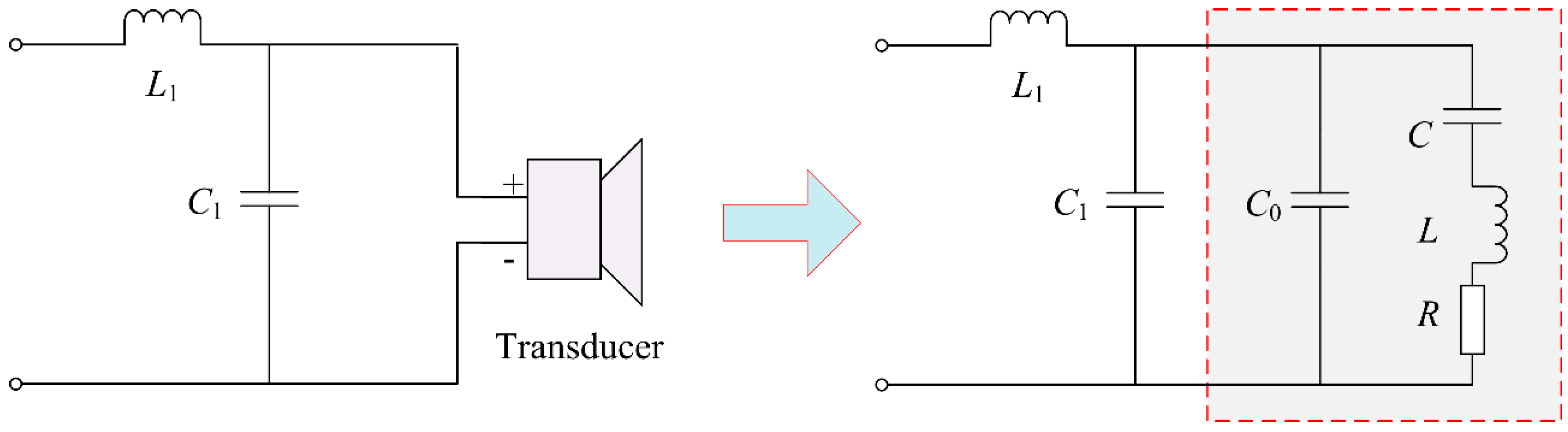
2. An Analysis of Ultrasonic Ranging Sensors and Their Impedance Matching Circuits
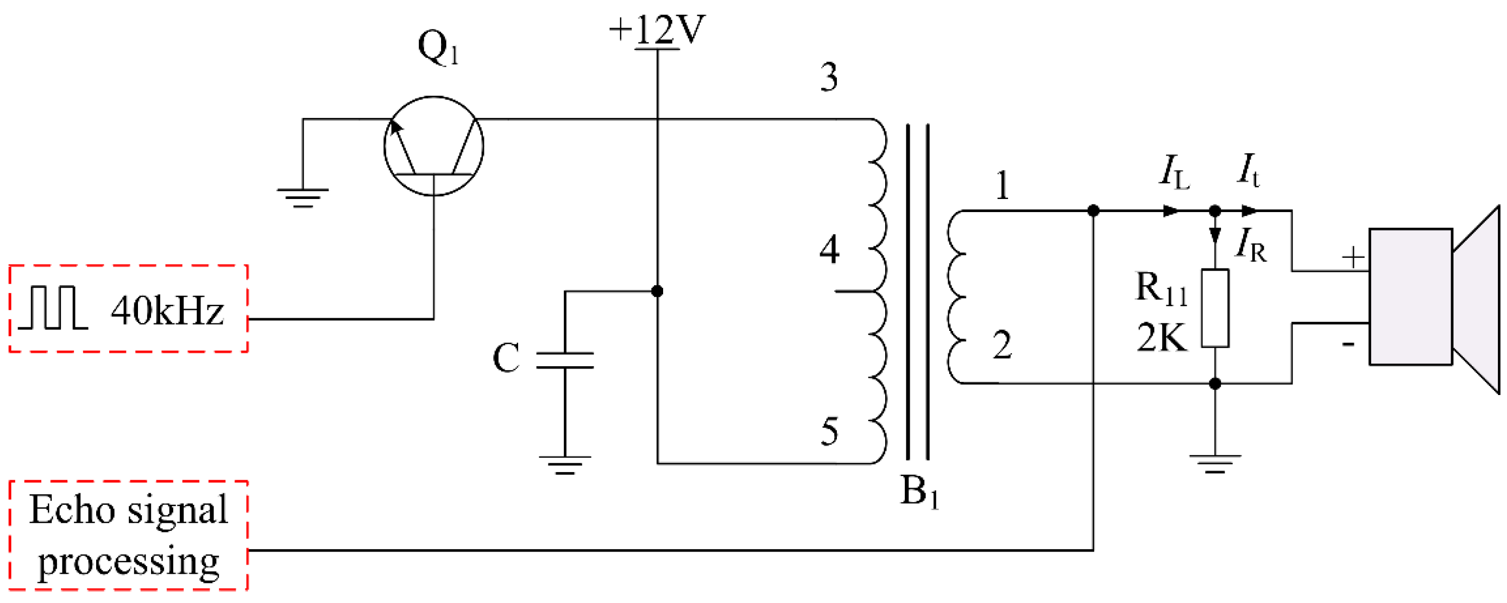
3. Analysis of Non-Intrinsically Safe Ultrasonic Driving Circuit
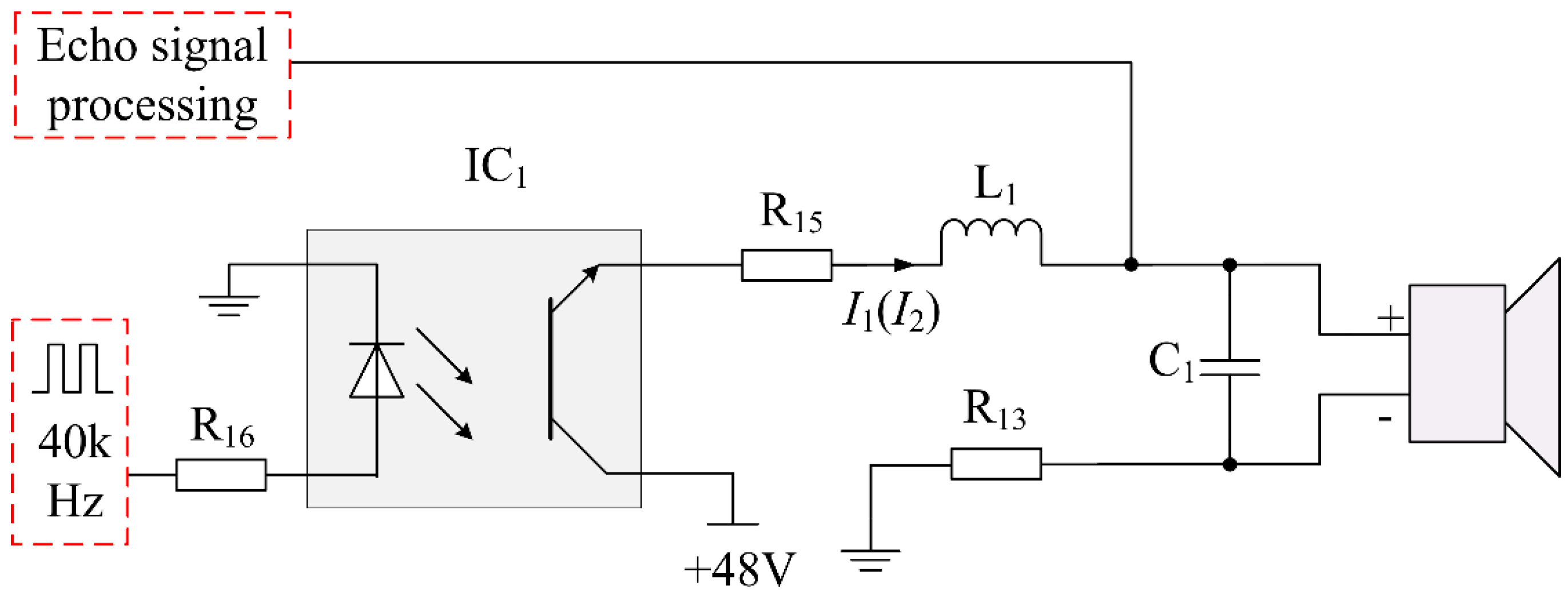
4. Analysis of Intrinsically Safe Ultrasonic Driving Circuit
4.1. Energy Limiting Circuit
Over-Voltage Protection
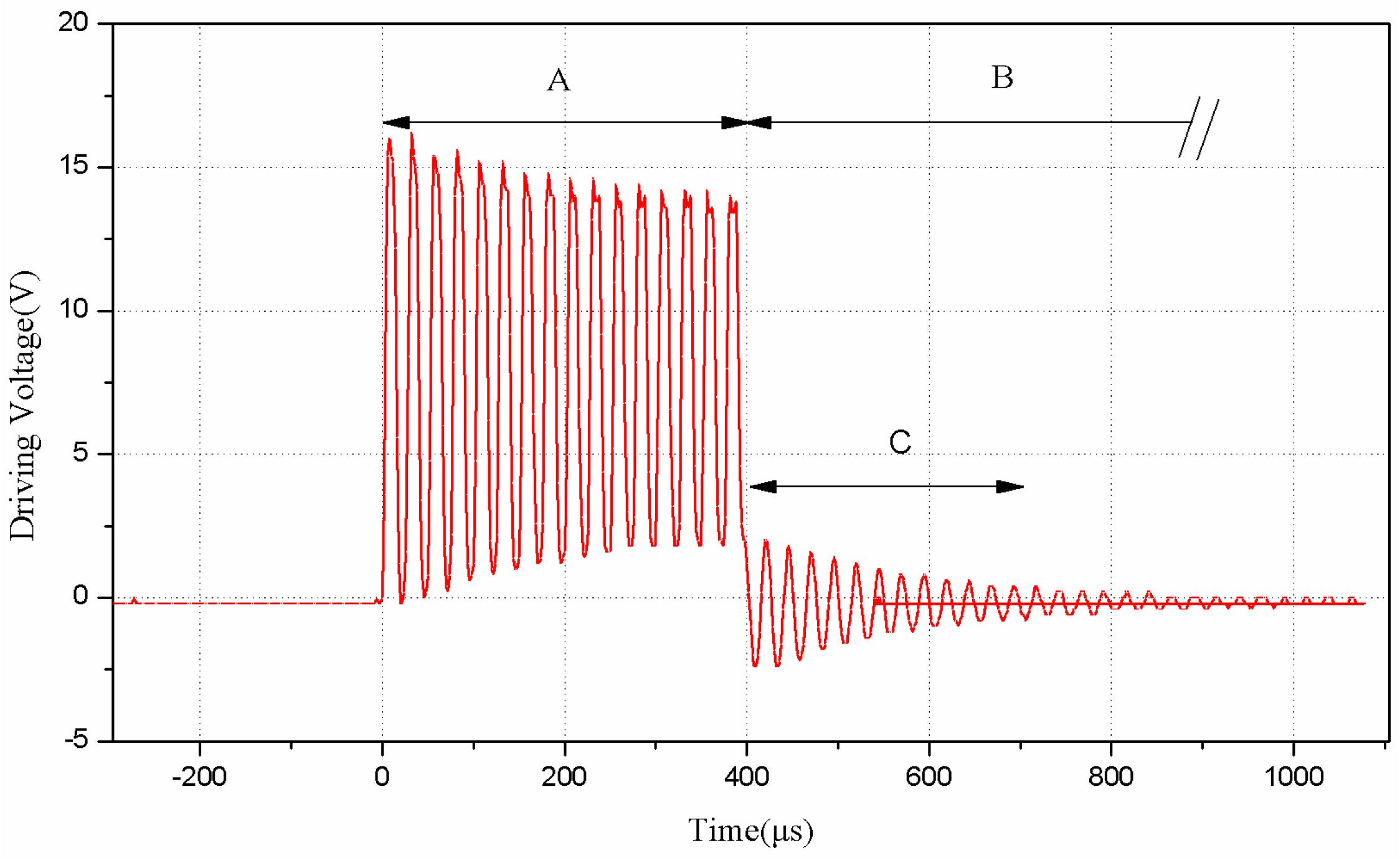
4.2. Design and Evaluation of an Intrinsically Safe Driving Circuit
5. Experimental Demonstration and Discussion
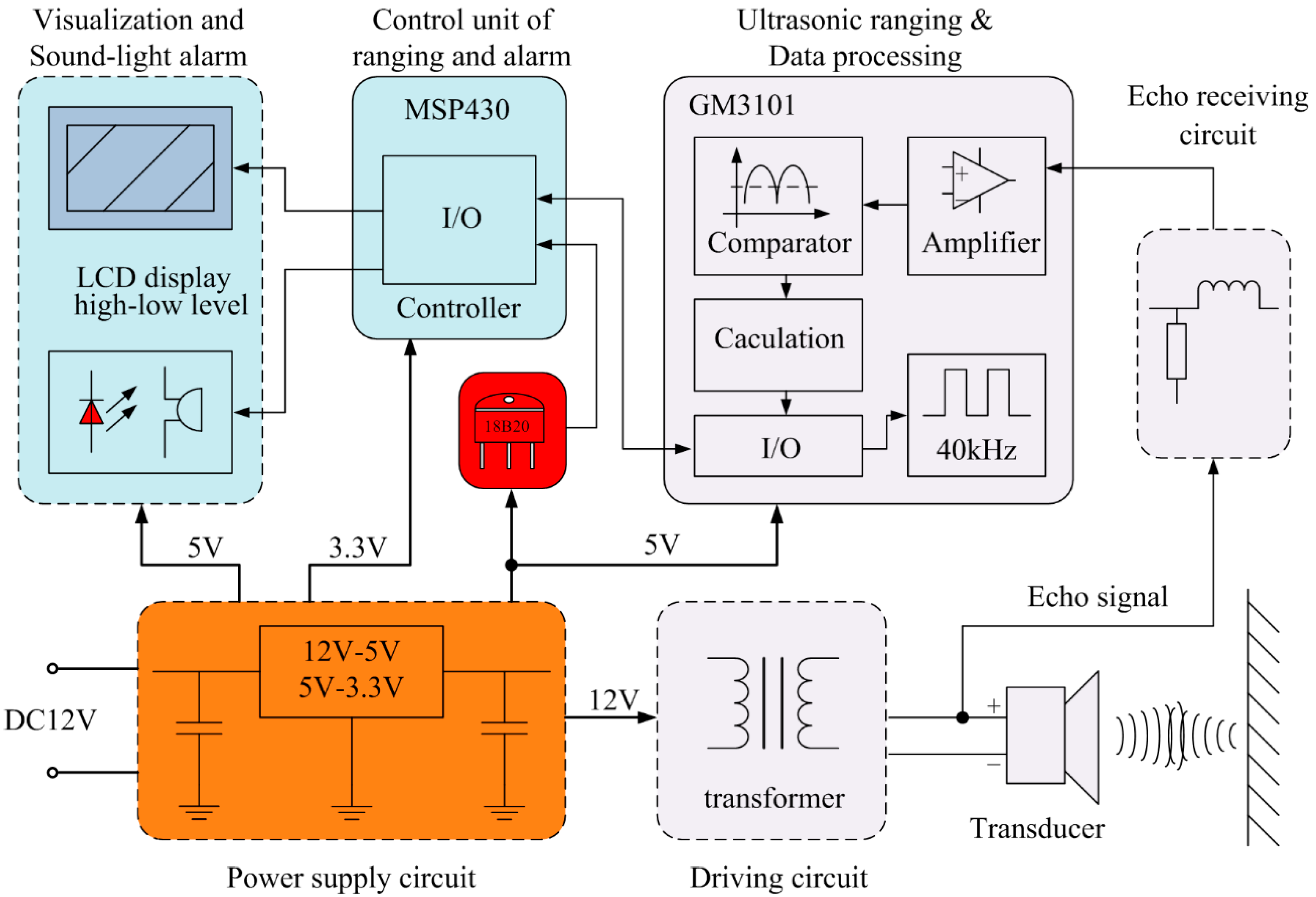
5.1. The Realization of the Distance Measurement Sensor
5.2. Experimental Setup and System Errors
5.3. Resolution and Blind Area
5.4. Linearity
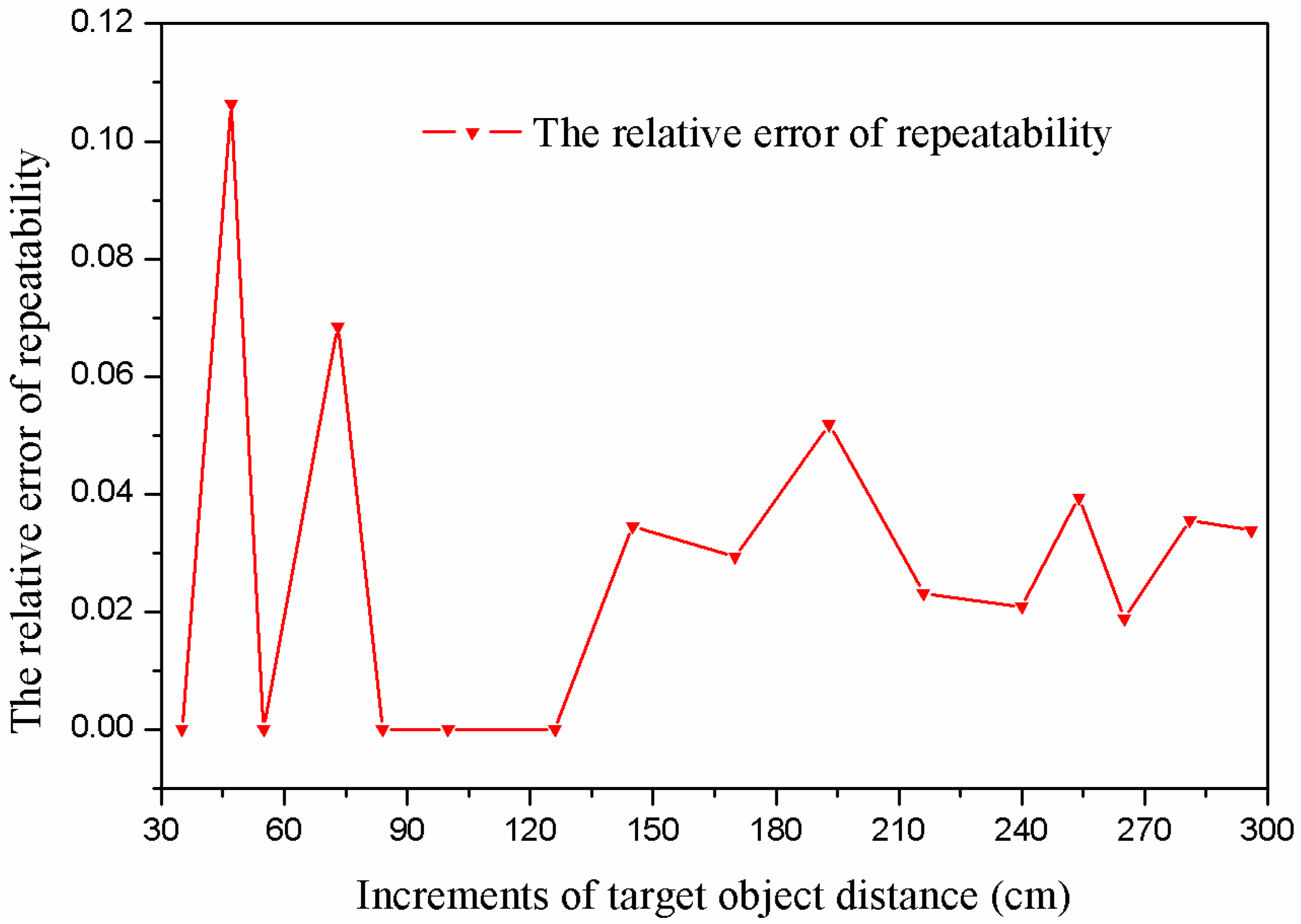
5.5. Repeatability
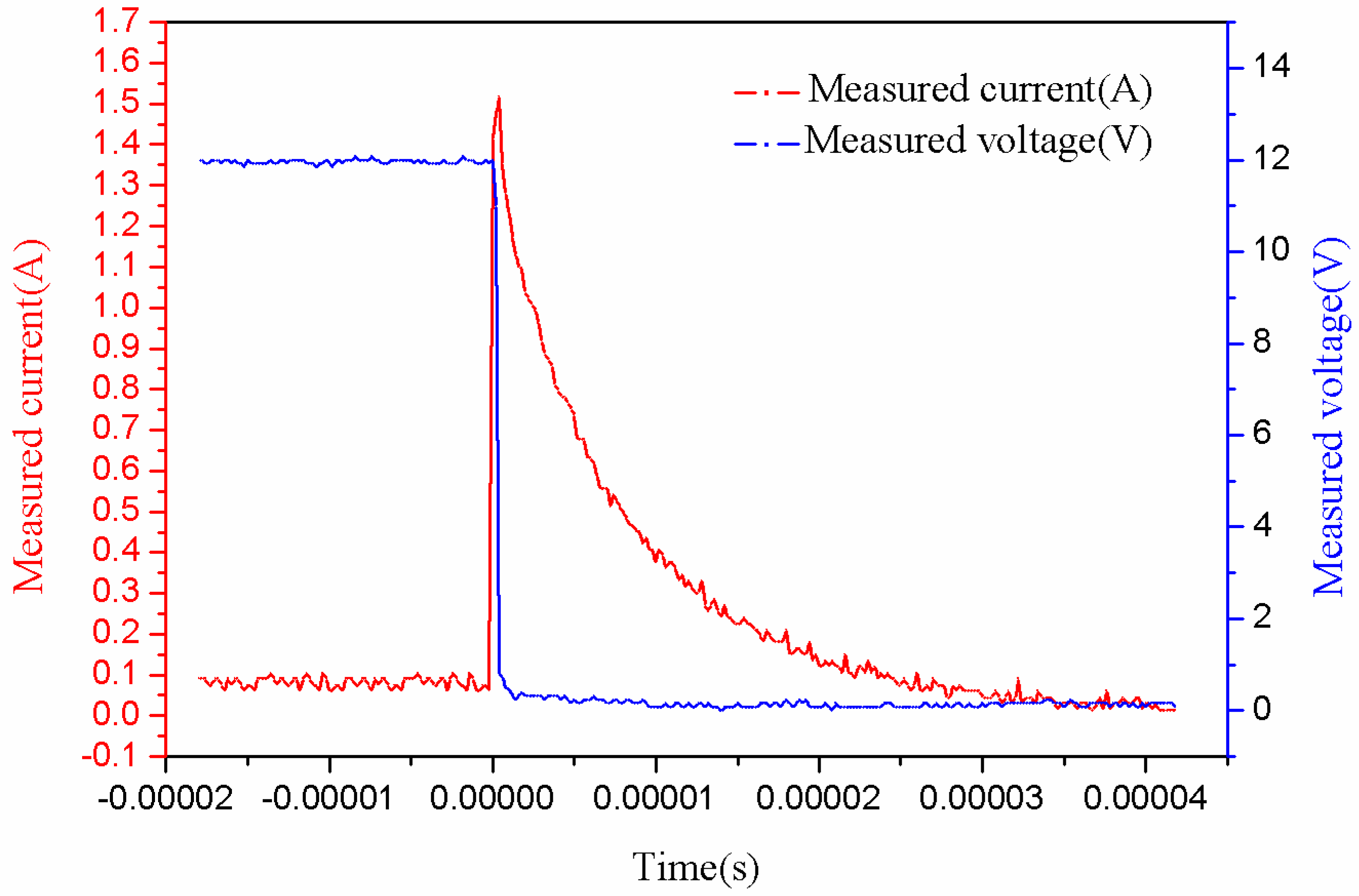
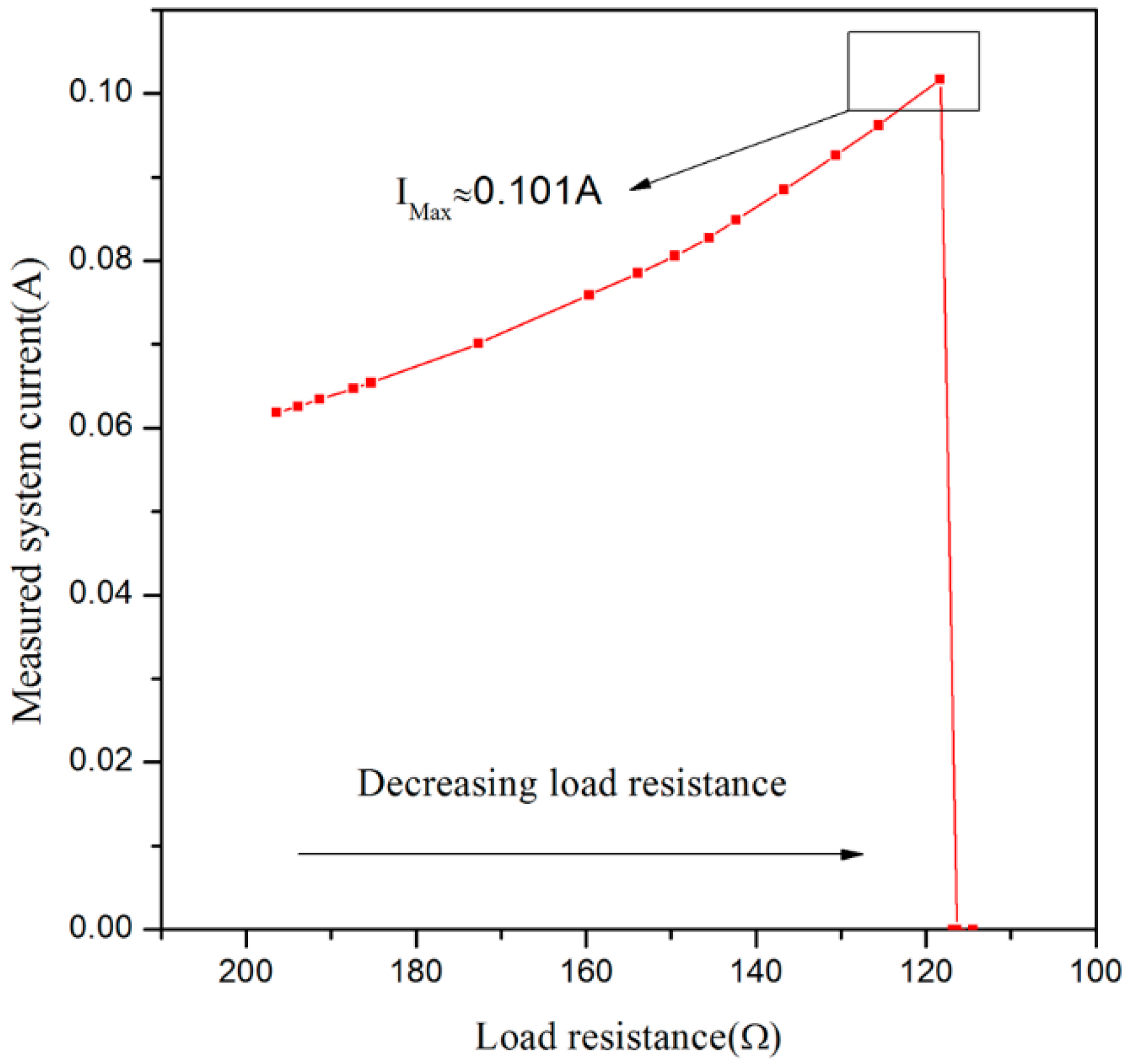
5.6. Short-Circuit Test
6. Conclusions
Acknowledgments
Author Contributions
Conflicts of Interest
References
- Lee, H.K.; Chang, S.I.; Yoon, E. Dual-Mode Capacitive Proximity Sensor for Robot Application: Implementation of Tactile and Proximity Sensing Capability on a Single Polymer Platform Using Shared Electrodes. IEEE Sens. J. 2010, 9, 1748–1755. [Google Scholar] [CrossRef]
- Norgia, M.; Magnani, A.; Pesatori, A. Absolute distance measurement system using a coherent optical sensor. In Proceedings of the 2012 IEEE International Instrumentation and Measurement Technology Conference (I2MTC), Graz, Austria, 13–16 May 2012.
- Azouigui, S.; Badr, T.; Wallerand, J.P.; Himbert, M.; Salgado, J.A.; Senelaer, J.P.; Kwasnik, F.; Juncar, P. Transportable Distance Measurement System for Long-Range Applications. IEEE Trans. Instrum. Meas. 2011, 60, 2678–2683. [Google Scholar] [CrossRef]
- Yang, M. Feedback controlled infrared proximity sensing system. Measurement 2015, 69, 81–86. [Google Scholar] [CrossRef]
- Benet, G.; Blanes, F.; Simó, J.E.; Pérez, P. Using infrared sensors for distance measurement in mobile robots. Robot. Auton. Syst. 2002, 40, 255–266. [Google Scholar] [CrossRef]
- Gądek, K.; Dudzik, M.; Stręk, A. A Novel Three-Head Ultrasonic System for Distance Measurements Based on the Correlation Method. Meas. Sci. Rev. 2014, 14, 331–336. [Google Scholar] [CrossRef]
- Alexandre, E.; Santiago, P.; Joan Ramon, R.; Jesús, P.; Ferran, C.; Francesc, S.; Felip, G.; Jordi, L.; Emilio, G. Performance of an ultrasonic ranging sensor in apple tree canopies. Sensors 2011, 11, 2459–2477. [Google Scholar]
- Schlegl, T.; Bretterklieber, T.; Neumayer, M.; Zangl, H. Combined Capacitive and Ultrasonic Distance Measurement for Automotive Applications. Sens. J. IEEE. 2011, 11, 2636–2642. [Google Scholar] [CrossRef]
- Yao, Z.J.; Meng, Q.H.; Zeng, M. Improvement in the accuracy of estimating the time-of-flight in an ultrasonic ranging system using multiple square-root unscented Kalman filters. Rev. Sci. Instrum. 2010, 81, 104901. [Google Scholar] [CrossRef] [PubMed]
- Jackson, J.C.; Summan, R.; Dobie, G.I.; Whiteley, S.M.; Pierce, S.G.; Hayward, G. Time-of-flight measurement techniques for airborne ultrasonic ranging. IEEE Trans. Ultrason. Ferroelectr. Freq. Control 2013, 60, 343–355. [Google Scholar] [CrossRef] [PubMed]
- Segers, L.; Tiete, J.; Braeken, A.; Touhafi, A. Ultrasonic Multiple-Access Ranging System Using Spread Spectrum and MEMS Technology for Indoor Localization. Sensors 2014, 14, 3172–3187. [Google Scholar] [CrossRef] [PubMed]
- Wan, D.Z.; Cheng, S.C. Simulation and prototype testing of a low-cost ultrasonic distance measurement device in underwater. J. Mar. Sci. Technol. 2014, 20, 142–154. [Google Scholar] [CrossRef]
- Huang, J.D.; Lee, C.K.; Yeh, C.S.; Wu, W.J.; Lin, C.T. High-Precision Ultrasonic Ranging System Platform Based on Peak-Detected Self-Interference Technique. IEEE Trans. Instrum. Meas. 2011, 60, 3775–3780. [Google Scholar] [CrossRef]
- Luis, G.D.J.; Antonio, M.F.; Jordi, L.; Andrés, C.; Blanco-Roldán, G.L.; Antonio, R.L. Testing accuracy of long-range ultrasonic sensors for olive tree canopy measurements. Sensors 2015, 15, 2902–2919. [Google Scholar]
- Bershadskii, I.A. A calculation method of chamberless thermal determination of intrinsic safety for electrical circuits. Russian Electr. Eng. 2013, 84, 422–430. [Google Scholar] [CrossRef]
- Kryca, M. Hardware Aspects of Data Transmission in Coal Mines with Explosion Hazard; Springer Berlin Heidelberg: Berlin, Germany, 2013; pp. 517–530. [Google Scholar]
- Jin, B.; Liu, X.; Bai, Q.; Wang, D.; Wang, Y. Design and Implementation of an Intrinsically Safe Liquid-Level Sensor Using Coaxial Cable. Sensors 2015, 15, 12613–12634. [Google Scholar] [CrossRef] [PubMed]
- Walpole, M.E. Intrinsically Safe (IS) Active Power Supplies. Master’s Thesis, Queensland University of Technology, Australia, March 2003. [Google Scholar]
- IEC/TC31: Explosive Atmospheres-Part 0: Equipment-General Requirements; IEC 60079-0-2007; International Electrotechnical Commission: Geneva, Switzerland, October 2007.
- Vazquez, C.; Gonzalo, A.; Vargas, S.; Montalvo, J. Multi-sensor system using plastic optical fibers for intrinsically safe level measurements. Sens. Actuators A Phys. 2004, 116, 22–32. [Google Scholar] [CrossRef] [Green Version]
- IEC/SC31G: Explosive Atmospheres-Part 11: Equipment Protection by Intrinsic Safety “i”; IEC 60079-11-2006; International Electrotechnical Commission: Geneva, Switzerland, July 2006.
- Peng, T.J.; Chang, Y.; Yang, Z.G.; Wu, B.D. Experiment Study on Inductance Match of Damping Ultrasonic Transducer. Piezoelectr. Acoustoopt. 2004, 26, 65–68. [Google Scholar]
- Licznerskia, T.J. Ultrasonic system for accurate distance measurement in the air. Ultrasonics 2011, 51, 960–965. [Google Scholar] [CrossRef] [PubMed]


| Parameter | Value | Uint |
|---|---|---|
| R | 200.00 | Ω |
| L | 166.64 | mH |
| L1 | 0.66 | mH |
| C | 0.10 | nF |
| C0 | 1.90 | nF |
| C1 | 22.0 | nF |
| Number | Designation | Version | Function |
|---|---|---|---|
| 1 | Distance measurement chip | GM3101 |
|
| 2 | Microprocessor | MSP430F149 |
|
| 3 | Display | LCD12864 |
|
| 4 | Sound and light alarm | Active buzzer and LED light-emitting diode |
|
| Specification | Value | Unit |
|---|---|---|
| Resolution | 5 | cm |
| Measuring range | 300 | cm |
| Maximum nonlinearity error | 2.22 | % FSS |
| Maximum repeatability error | 10 | cm |
| Critical value of over-voltage protection | 12.45 | V |
| Critical value of over-current protection | 0.101 | A |
| Short-circuit response time | 0.4 | μs |
© 2016 by the authors; licensee MDPI, Basel, Switzerland. This article is an open access article distributed under the terms and conditions of the Creative Commons Attribution (CC-BY) license (http://creativecommons.org/licenses/by/4.0/).
Share and Cite
Zhang, H.; Wang, Y.; Zhang, X.; Wang, D.; Jin, B. Design and Performance Analysis of an Intrinsically Safe Ultrasonic Ranging Sensor. Sensors 2016, 16, 867. https://doi.org/10.3390/s16060867
Zhang H, Wang Y, Zhang X, Wang D, Jin B. Design and Performance Analysis of an Intrinsically Safe Ultrasonic Ranging Sensor. Sensors. 2016; 16(6):867. https://doi.org/10.3390/s16060867
Chicago/Turabian StyleZhang, Hongjuan, Yu Wang, Xu Zhang, Dong Wang, and Baoquan Jin. 2016. "Design and Performance Analysis of an Intrinsically Safe Ultrasonic Ranging Sensor" Sensors 16, no. 6: 867. https://doi.org/10.3390/s16060867