
Domotics Project Housing Block


Grupo de Sensores y Actuadores, Dpto. Tecnología de la Edificación, Universidad Politécnica de Madrid, 28040 Madrid, Spain
*
Author to whom correspondence should be addressed.
Sensors 2016, 16(5), 741; https://doi.org/10.3390/s16050741
Submission received: 15 March 2016
/
Revised: 10 May 2016
/
Accepted: 17 May 2016
/
Published: 23 May 2016
(This article belongs to the Special Issue Selected Papers from the 2nd International Electronic Conference on Sensors and Applications)
Abstract
:This document develops the study of an implementation project of a home automation system in a housing placed in the town of Galapagar, Madrid. This house, which is going to be occupied by a four-member family, consists of 67 constructed square meters distributed in lounge, kitchen, three bedrooms, bath, bathroom and terrace, this being a common arrangement in Spain. Thus, this study will allow extracting conclusions about the adequacy of the home automation in a wide percentage of housing in Spain. In this document, three house automation proposals are developed based on the requirements of the client and the different home automation levels that the Spanish House and Building Automation Association has established, besides two parallel proposals relating to the safety and the technical alarms. The mentioned proposed systems are described by means of product datasheets and descriptions, distribution plans, measurements, budgets and flow charts that describe the functioning of the system in every case. An evaluation of each system is included, based on other studies conclusions on this matter, where expected energy savings from each design, depending on the current cost of lighting, water and gas, as well as the expected economic amortization period is evaluated.
1. Introduction
Usually, in the building sector, it is forgotten that the right functioning of a building does not exclusively depend on its distribution, constructive features or facilities. Actually, the most important factor is the way the building is used.
In this field, domotics play a vital role, getting the most of its facilities and constructive features. The domotics concept, as home automation, develops new systems that are able to automatize common functions in households from developed countries, like electrical facilities management, audiovisual systems, etc. However, currently, there is another concept related to domotics, considered the next step in this area. Smart house concept, apart from home automation, includes central data control of the elements of the system [1].
Domotics is an essential part of the future of building sector, in which some new services and comforts will be integrated in households. Nowadays, this automation is becoming very important for building energy efficiency, and reducing energy consumption [2] and CO2 emissions. These facts are demonstrated in the study of Ippolito [3], in which the certification level is improved, according to EN15217 standard [4].
One of the cornerstones in which more efforts are being carried out, is energy efficiency, including making passive systems into active systems, regulating demand, and adapting these systems to the usage of the building [5]. In fact, in some cases, consumption peaks have been decreased by 46% [6]. There is hope that these systems will be more affordable, while maintaining their efficiency [7].
Furthermore, we should not forget that these systems produce intangible benefits for the user. Feeling protected against theft, preventing installation failures, and increased comfort level because of the control of environmental variables are added to energy efficiency benefit with the consequent economic savings.
These systems are objects of continuous improvement, making Home Building Automation System (HBAS) or Building Automation System (BAS) more reliable and robust. In addition, model-based and interactive simulations have been developed [8]. Another example is the inclusion of wireless technologies like ZigBee or 6LoWPAN, favoring their interoperability [9].
The inclusion of more and better sensors improves the ability of the system to adapt to the environment and promote the requirements for keeping desired conditions, using a minimum of energy for that performance. Examples might include the inclusion of rain, solar radiation (direct or diffuse), and humidity or wind sensors, among others [10].
On the other hand, from the user´s point of view, many different services have been created. Internet Protocol Television (IPTV) services [11] or Android supported scalable home automation systems [12] are two examples. Moreover, some studies are focused on creating systems that help dependent people, including elderly people, such as the low-cost system by Dasios et al. [13] or the security and comfort system from Carpio et al. [14]. Other systems are capable of gathering data via the Internet from public Application Programming Interfaces (APIs) [15]. It is also important to include multi-agent platforms such as PANGEA, used in the work of Villarubia et al. [16].
More in general, greenhouses are a good example. In them, climatic conditions control is essential for the installation’s function and automatic devices are proving to be very useful [17].
Many technologies are used in domotics area, creating a worrying heterogeneity in this area [18]. Among the various domotics technologies, there are two manufacturers that are more representative because of their major contribution to the area, LonWorks, prevailing in North America, and Konnex (KNX) in Europe. There are a great number of works based on KNX technology that demonstrate its great utility in home data gathering [19]. Moreover, a KNX system can link the city in which it is situated to its resources management system [20].
In this work, a domotics system implementation in a flat located in Galapagar (Spain) based on KNX technology is studied [21].
To create a more detailed study, three systems have been implemented to achieve each level of home automation specified in UNE-CLC/TR 50491-6-3:2013 IN [22]. Furthermore, we also designed and installed two independent modules compatible with the above-mentioned systems, a security subsystem and a system related to technical alarms.
The aim of this work is to carry out a viability study of each KNX system level for small apartments. This viability is studied in regard to economic, environmental and energy decisions. Moreover, we have gathered data about energy savings of each system and they have been compared according to the three mentioned areas. We have also simulated with SeeTool® software the results of two more real small apartments (Barcelona and A Coruña) with the same orientation located in different climate zones.
For this purpose, and after implementation of these systems in the flat, a quantitative analysis of energy and economic variables has been carried out as well as a second qualitative study made by means of satisfaction surveys that contain comfort and security questions, after the user had been living together with the systems.
Based on these two analyses, we present several conclusions about the influence of each system in user’s life and the energy and economic savings these systems have resulted in.
2. Materials and Methods
2.1. Subject of Research
We have designed and installed a home automation in a flat located in Galapagar (Spain). This flat has a north orientation and consists of 67 m2 usable space over a 79 m2 constructed area, distributed in several rooms: a living room-kitchen-hall (26.80 m2), a master bedroom (12.29 m2), two additional bedrooms (10.24 and 8.34 m2), a bathroom (3.72 m2), a toilet (1.61 m2), one corridor (3.40 m2) and a terrace (12.24 m2).
2.2. General Features of the Home Automation System
- Physical level: In this case, a TP1 wiring type for data transmission was chosen. The choice of a wired system instead of a wireless solution, which is a rising technology, is due to the fact that this flat was to be integrally rehabilitated. This makes the added costs of wiring not so high. Apart from that, wiring solutions are highly reliable and using them, we can eliminate added electromagnetic contamination [23], which has been increasing for the last years because of the uncontrolled advance of technology. It makes wiring solutions a solution to take into consideration.
- Topology: We have chosen a data bus composed of lines and areas joined by line-couplers (LC) and backbone/area couplers. Each line can host 64 devices, and each area can be formed for up to 15 lines. Each line is powered by a 24 V DC power supply, and each one supports 640 mA with a cushioning time of 100 ms.
- Network design: Each device in this system consists of a microcontroller with memory. This way, we have achieved a distributed architecture, in which if one device fails, it will not affect the functioning of the whole system. Furthermore, it facilitates possible future expansions of the system. Each device is individually programmed.
- Protocol: This system is based on KNX standard because it is an already-tested system and because of its reliability and compatibility with many products from different manufacturers. The information is symmetrically sent by both conductors as an alternating signal superimposed on a 24 V dc current. Likewise, KNX use Carrier sense multiple access with collision avoidance (CSMA/CA) network multiple access method in which carrier sensing is used, but nodes attempt to avoid collisions by only transmitting when the channel is sensed to be clear.
- Devices: Each device consists of three elements, bus coupler, which is composed of three memory chips (EPROM, ROM and RAM); an external-physical interface; and an application module.
2.3. Common Elements
Regardless of the home automation level, there are some elements that are common to all systems being implemented in them. The first one is the power supply; it is necessary to generate the needed voltage in each line. The power supplies we have chosen are suitable with uninterruptible supply systems (UPS) in order to meet the line needs. An uninterruptible power supply that consist of a lead-gel battery is also part of our system.
To control our system, we have used a control panel. It consists of a touchscreen with which the user can interact. It is fed from the 230 V mains, allows for updating via USB, and has password protection and remote-LAN programming. Furthermore, it includes the needed coupler for its integration in the system.
A KNX-IP gateway is necessary for providing external communication to the intermediate and advanced level, which allow for accessing the bus remotely. By this access, we have been able to carry out the programming of the system through a Virtual Private Network (VPN) configuration. System maintenance and diagnosis during full operation, and device management, have been carried out by means of InSideControl® software. It requires a 24 V DC power supply and a modem/router Internet connection by RJ45 wire.
For line-main line connections or union of new areas with prior areas, we have installed line couplers. This device allows us to set up, according to some parameters, its behavior as a coupler or booster. This eases the effective range expansion of the bus. This also allows for void filter option to test the system. It has two connection terminals.
Finally, apart from the above-mentioned wire, connection terminals have been used to create branch lines or to connect some devices. To this aim, a product that allows the connection of four pairs with a single 0.6–0.8 diameter connection terminal was chosen.
In the following lines, we have described technical features of each implemented systems by means of tables and flow charts in order to ease the understanding of its function.
2.4. Data Acquisition (DAQ) System
A Data Acquisition (DAQ) system with several data loggers (MICROLITE 8/16), which allow us to capture lots of measures, has been implemented. These data loggers were integrated in all systems installed. The data were gathered every 20 min and once a month, there data are sent to a PC. Later, data are analyzed using several specialized software packages to obtain all the results presented in this paper.
3. Home Building Automation Systems
3.1. Basic Home Automation System
The basic system (home automation level 1) permits an automatic and efficient control over the lighting and air conditioning subsystem by means of several types of sensors and actuators, which are summarized in Table 1 and Table 2.
For the purpose of offering the user the possibility of managing the room’s temperature, a thermostat has been installed next to each bed. With it, the user can control the environment based on four stages, two hot/cold stages and two other auxiliary stages. In the event of voltage loss, the program saves itself and recovers automatically.
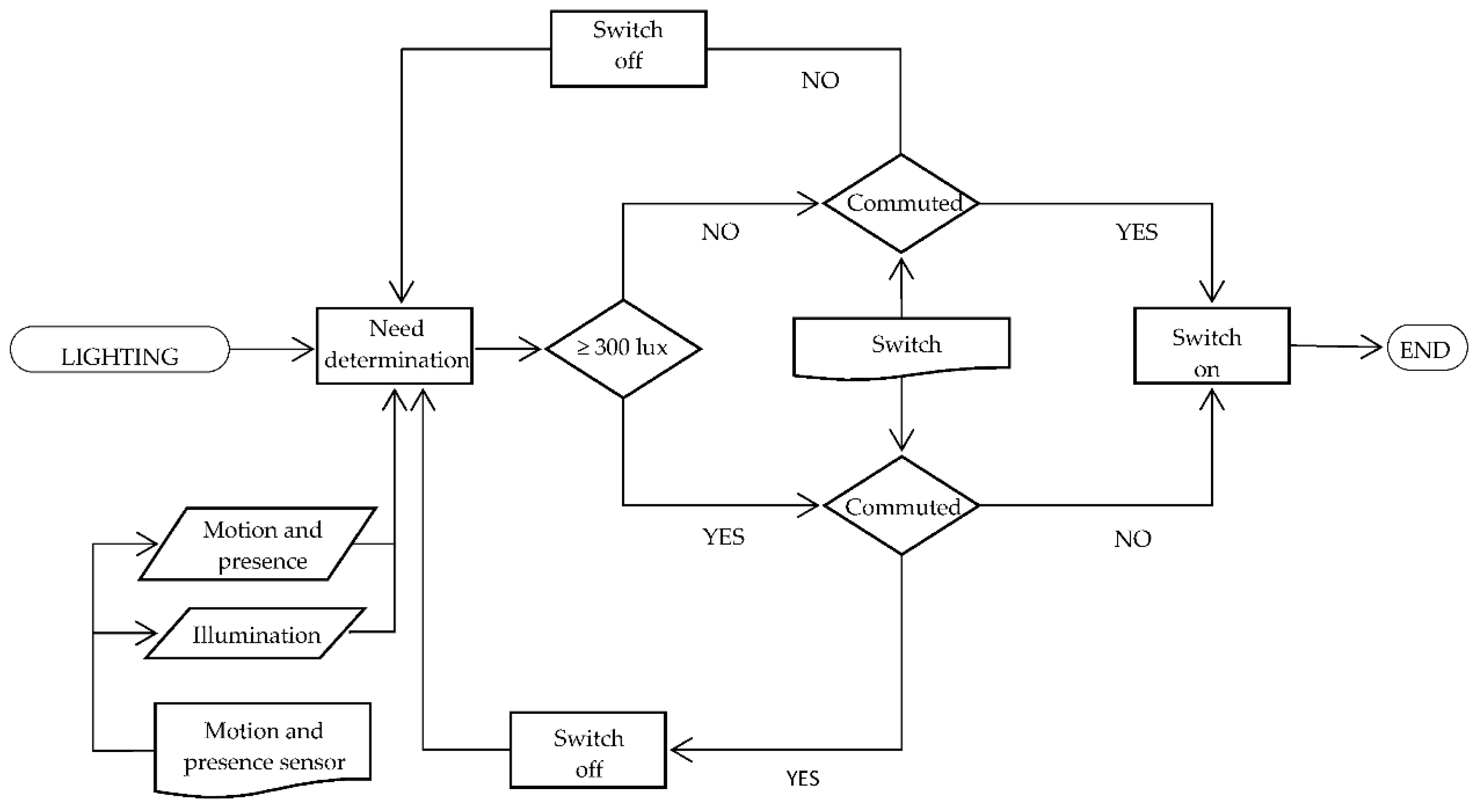
In addition, we have installed a split control interface to establish a link between KNX system and air conditioners. It enables user control over devices by means of thermostats, avoiding remote control use. Figure 1 and Figure 2 are the air conditioning and lighting functioning flow charts, respectively.
Lastly, general features of our basic-level system are presented in Table 3.
Because the number of devices is less than 64, it is possible to use only one line. However, the user will be limited if he wants to make enhancements. For this reason, we have installed lines in accordance with advanced system requirements. Our components (sensors, actuators, etc.) and line distribution all over the flat is reflected in Figure 3.
3.2. Intermediate Home Automation System
This system (home automation level 2) permits an automatic and efficient control over the lighting, air conditioning, water resources and the electrical power demand of the house. This system consists of the above-mentioned sensors and actuators in Table 1 plus the sensors and actuators in Table 4.
Five switches were also installed, each one situated next to each window. Finally, general features of our intermediate-level system are presented in Table 5.
3.3. Advanced Home Automation System
In this case, this system reaches a home automation level of 3. Apart from the functions that the intermediate system provides (automatic control over air conditioning, lighting, water resources and electrical power demand), it manages automatically dimmable lights and a multimedia system that is able to play sounds from several points of the flat. In addition, it can reproduce pre-recorded messages. What is more, it senses the presence and manages the dimmable lights situated in the terrace. Finally, it accurately senses the temperature gradient, and regulates the actuators, avoiding unpleasant currents. All of this is thanks to the sensors and actuators presented in Table 6.
To finish the description of the advanced home automation system, we present in Table 7 the general features of the system.
3.4. Technical Alarms Subsystem
This subsystem is attachable to the above-mentioned systems and it has the function of reporting to the user possible home disasters that might arise from facilities’ breakdowns such as fire, gas leakage or flooding. The installation of this subsystem means that an additional line and its respective area configuration, a power supply and an additional line coupler have to be added.
In order to avoid any unnecessary duplicity of elements, common elements between the systems and this subsystem are summarized below in Table 8.
Data are gathered from the sensors according to the table below (Table 9) and installed actuators are summarized in the same table.
3.5. Security Subsystem
Similar to the technical alarm subsystem, the security subsystem is attachable to the above-mentioned home automation systems. Its main functions are to detect intrusions and potential failures that may ease them. It has direct external contact with the user and it can be installed in as an independent system. Its common elements with the main home automation systems are presented in Table 11.
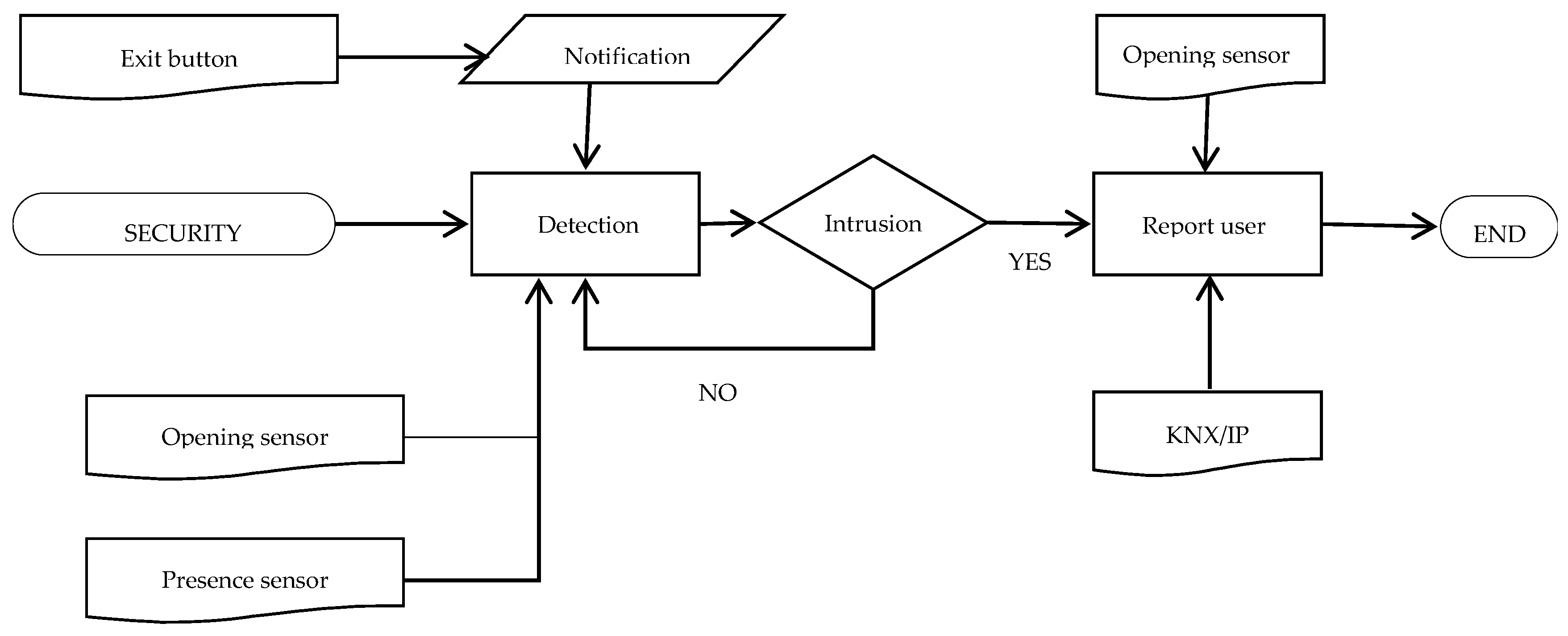
Data gathered by the sensors (Table 12) are sent to a central security unit where the data are processed and, if needed, this central reports the user the information by means of InsideControl®. A button has also been installed to communicate with the subsystem an “Out of the house” or “In the house” state. A LED light changes color according to the state previously communicated. In Figure 5, a flow chart describes the working of this subsystem.
4. Results
After home automation systems implementation, several studies have been carried out, separated according to different variables.
In the following tables, the results are shown divided into subsections according to the same previous variables. These results are based on the coexistence of a family comprised of four people and the systems described.
4.1. Energy Study
4.2. Economic Study
4.3. Environmental Impact Study
We have studied CO2 emissions of the systems with the following results summarized in Table 17. In Table 18, percentages of savings depending on the areas in study and different locations [25] are summarized. These percentages have been obtained using SeeTool® software introducing similar and real flats with the same orientation.
4.4. Non-Quantifiable Study
Apart from quantifiable variables, there are other system properties that the users appreciate when the system is implemented in their home. During the implementation phase and after the user–system coexistence phase, some questions were asked to the users.
Most of them, noted as the main benefit, the comfort the system provides to the user. The next most appreciated property was the remote control of their homes.
Finally, but still important, the users emphasize the calm feeling from technical alarms and security subsystems.
5. Discussion
Two main comparisons have been carried out. The first one (Figure 6) compares the energy savings produced by the three domotics levels grouping lighting and conditioning consumptions.
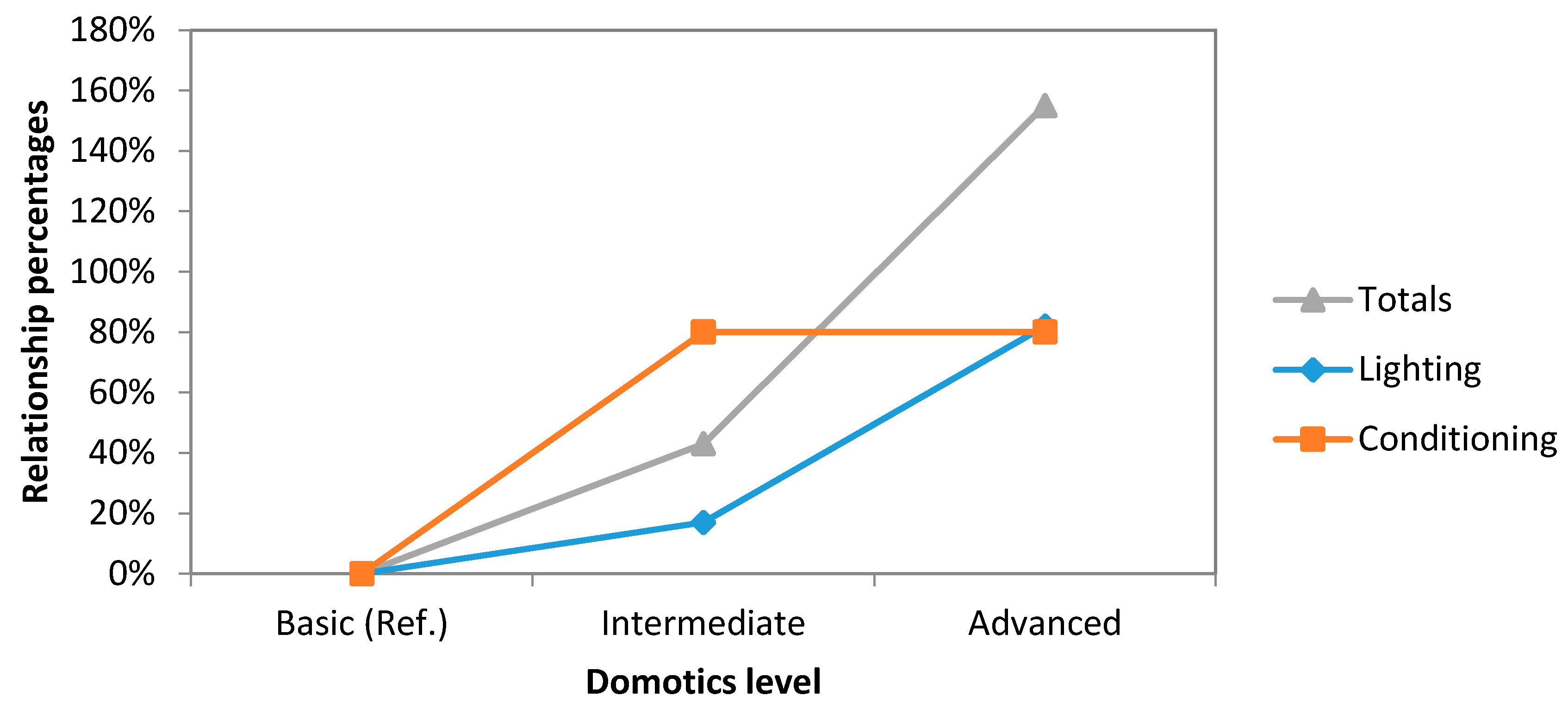
Furthermore, in the second (Figure 7), with the same groups, the relationship percentages between our systems has been compared.
Analyzing these two graphs, it can be noticed that the savings on lighting area have a linear trend while new improvements are made to our system, increasing the level of automation. However, this trend changes in economic area. There exists a higher increase in costs when the system levels up to advanced level from the intermediate one.
With regard to conditioning, its behavior is the same as the previous relation, no change existing between advanced and intermediate level but producing great savings. If we compare the intermediate system with respect to the basic one, the savings are improved by 123%.
As we can see in Figure 7, investments in installing the intermediate system only increase by 43% when the system levels up from basic system. However, this increase is multiplied by a factor of three if we compare it with the advanced system investment.
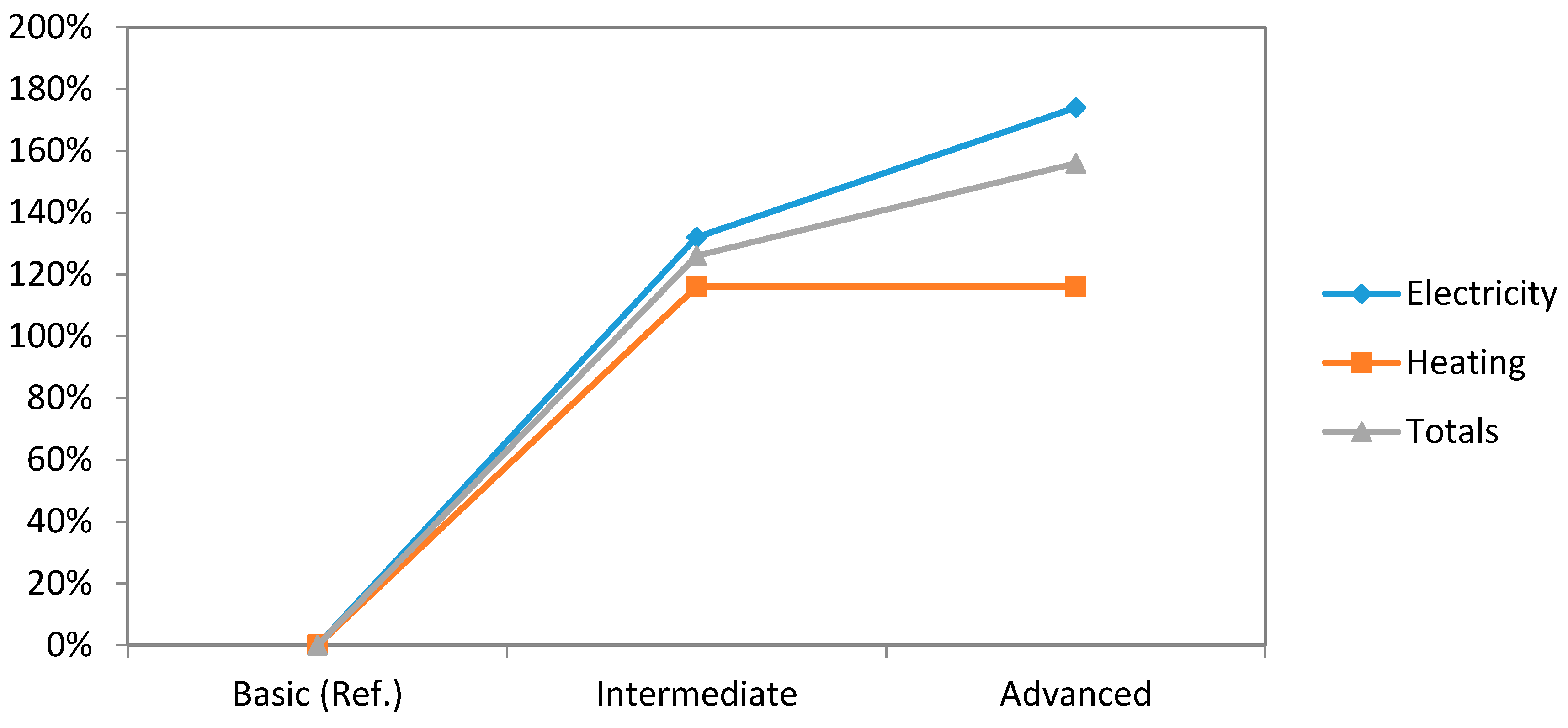
In Figure 8, the comparative graph concerning to energy savings of our three levels of automation related to electricity and heating areas can be found. Electricity area greatly increases on the passage from basic system to the intermediate one. This increase is stopped in intermediate-to-advanced step, reducing the relationship percentage of energy savings by 18%. Heating becomes stagnant at the same step.
If we compare these data and CO2 emissions (Figure 9), it is noticed that CO2 reduction comes from the savings done in electricity area and, especially, in the step from basic to intermediate level.
After we installed the home automation system, several surveys about its energy, economic and environmental impact have been done based on the four people who live in this flat. The results of these surveys show that our system achieves energy savings of 19.88% in lighting and 16.09% in air conditioning per year, as well as a reduction of CO2 emissions of 76.03 Kg/month (basic system). All of this implies economical savings of 300 €/year (basic system), and an amortization of the investment that has been made of 20 years (intermediate system).
It is important to notice that advanced system is not as good as expected. Its results are not much better than intermediate system results, being its implementation costs are 78% higher. Probably, its influence only in lighting area is not worthwhile. In the future, in order to get more economic savings, advanced system should take into consideration new tools in air conditioning area or some others that increase, significantly, these savings.
Apart from measurable factors, there are other not-measurable benefits that the user consider when implementing home automation systems. These are the acquired comfort and security feeling because of the security and technical alarms subsystems.
6. Conclusions
The implemented system in this dwelling offers a great number of objective advantages, having as its mainstay the energy savings, which also lead to economic savings and to a reduction of CO2 emissions, which is, nowadays, so valuable. It is also important to appreciate positively the increase in comfort and security that this system provides to the user.
Intermediate-to-advanced level up increases the costs of the system but there is little added economic savings; thus, the intermediate level is the most adequate for a small apartment typology.
Climatic zones also influence on these savings; thus, apartment location is very important when choosing the best level of the home automation system.
The 20-year amortization, at best, is insufficient to conclude that the system is economically viable. This fact becomes a pending task that we will have to improve in the future to enter individual user market.
Acknowledgments
This work has been supported by Universidad Politécnica de Madrid and PROIESCON company.
Author Contributions
All the authors conceived, designed and performed the experiments. Additionally, all the authors analyzed the data and participated in writing the paper.
Conflicts of Interest
The authors declare no conflict of interest.
Abbreviations
| HBAS | Home Building Automation System |
| BAS | Building Automation System |
| IPTV | Internet Protocol Television |
| API | Application Programming Interface |
| KNX | Konnex |
| CSMA/CA | Carrier sense multiple access with collision avoidance |
| EPROM | Erasable Programmable Read-Only Memory |
| ROM | Read-Only Memory |
| RAM | Random Access Memory |
| VPN | Virtual Private Network |
| DAQ | Data Acquisition |
| UPS | Uninterruptible power supply |
References
- Flórez, M. Smart houses, towards a definition. Inf. Constr. 2004, 56, 11–17. [Google Scholar]
- Missaoui, R.; Joumaa, H.; Ploix, S.; Bacha, S. Managing energy smart homes according to energy prices: Analysis of a building energy management system. Energy Build 2014, 71, 155–167. [Google Scholar] [CrossRef]
- Ippolito, M.G.; Sanseverino, E.R.; Zizzo, G. Impact of building automation control systems and technical building management systems on the energy performance class of residential buildings: An Italian case study. Energy Build. 2014, 69, 33–40. [Google Scholar] [CrossRef]
- EN 15217:2007. Energy performance of buildings. Methods for expressing energy performance and for energy certification of buildings. June 2007. Available online: http://www.aenor.es/aenor/normas/normas/fichanorma.asp?tipo=N&codigo=N0049346#.Vz7Jcnu3zCR (accessed on 20 May 2016).
- Teich, T.; Wolf, S.; Neumann, T.; Junghans, S.; Franke, S. Concept for a Service-Oriented Architecture in Building Automation Systems. Proc. Eng. 2014, 69, 597–602. [Google Scholar] [CrossRef]
- Caprino, D.; Della Vedova, M.; Facchinetti, T. Peak shaving through real-time scheduling of household appliances. Energy Build. 2014, 75, 133–148. [Google Scholar] [CrossRef]
- Shafik, A. Smart metering and home automation solutions for the next decade. In Proceedings of the 2011 International Conference on Emerging Trends in Networks and Computer Communications (ETNCC), Udaipur, India, 22–24 April 2011; pp. 200–204.
- Synnott, J.; Nugent, C.; Jeffers, P. Simulation of Smart Home Activity Datasets. Sensors 2015, 15, 14162–14179. [Google Scholar] [CrossRef] [PubMed]
- Gomez, C.; Paradells, J. Wireless Home Automation Networks: A Survey of Architectures and Technologies. IEEE Commun. Mag. 2010, 48, 92–101. [Google Scholar] [CrossRef]
- Vähä, P.; Heikkilä, T.; Kilpeläinen, P.; Järviluoma, M.; Gambao, E. Extending automation of building construction—Survey on potential sensor technologies and robotic applications. Autom. Constr. 2013, 36, 168–178. [Google Scholar] [CrossRef]
- Umberger, M.; Humar, I.; Kos, A.; Guna, J.; Žemva, A.; Bešter, J. The integration of home-automation and IPTV system and services. Comput. Stand. Interfaces 2009, 31, 675–684. [Google Scholar] [CrossRef]
- Korkmaz, I.; Metin, S.K.; Gurek, A.; Gur, C.; Gurakin, C.; Akdeniz, M. A cloud based and Android supported scalable home automation system. Comput. Electr. Eng. 2015, 43, 112–128. [Google Scholar] [CrossRef]
- Dasios, A.; Gavalas, D.; Pantziou, G.; Konstantopoulos, C. Hands-On Experiences in Deploying Cost-Effective Ambient-Assisted Living Systems. Sensors 2015, 15, 14487–14512. [Google Scholar] [CrossRef] [PubMed]
- Cárdenas Sanchez, T.A.; Chavez Burbano, P.X.; Carpio Miranda, M.E. Desarrollo e Implementación de un Sistema de Seguridad y Confort para Hogares Monitoreado y Administrado a través de una Aplicación web; Resumen, Escuela Superior Politécnica del Litoral (ESPOL): Guayaquil, Ecuador, 2014. [Google Scholar]
- Oliveira-Lima, J.A.; Delgado-Gomes, V.; Martins, J.F.; Lima, C. Standard-based service-oriented infrastructure to integrate intelligent buildings in distributed generation and smart grids. Energy Build. 2014, 76, 450–458. [Google Scholar] [CrossRef]
- Villarrubia, G.; De Paz, J.F.; Bajo, J.; Corchado, J.M. Ambient agents: Embedded agents for remote control and monitoring using the PANGEA platform. Sensors 2014, 14, 13955–13979. [Google Scholar] [CrossRef] [PubMed]
- Kolokotsa, G.; Saridakis, G.; Dalamagkidis, K.; Dolianitis, S.; Kaliakatsos, I. Development of an intelligent indoor environment and energy management system for greenhouses. Energy Conver. Manag. 2010, 51, 155–168. [Google Scholar] [CrossRef]
- Bernheim Brush, A.J.; Lee, B.; Mahajan, R.; Saroiu, S.; Dixon, C. Home Automation in the Wild: Challenges and Opportunities. In Proceedings of the CHI, Vancouver, BC, Canada, 7–12 May 2011.
- Matijevics, E. Measurement Data Collecting into Databases from KNX Systems. In Proceedings of Intelligent Systems and Informatics (SISY), Subotica, Serbia, 8–10 September 2011; pp. 315–321.
- Sita, I.V.; Dobra, P. KNX Building Automations Interaction with City Resources Management System. Proc. Technol. 2014, 12, 212–219. [Google Scholar] [CrossRef]
- KNX Association Official Website. Available online: http://www.knx.org (accessed on 21 September 2015).
- UNE-CLC/TR 50491-6-3:2013 IN. General Requirements for Home and Building Electronic Systems (HBES) and Building Automation and Control Systems (BACS)—Part 6–3: HBES Installations-Assessment and Definition of Levels. 24 July 2013. Available online: http://www.aenor.es/aenor/normas/normas/fichanorma.asp?tipo=N&codigo=N0051508#.Vz0isXu3zCQ (accessed on 19 May 2016).
- Méndez, A.; Román, F.; Ramírez, A. Alteraciones fisiológicas por exposición crónica a intensos campos electromagnéticos. Acta Méd. Colomb. 1995, 20, 214–221. [Google Scholar]
- Gómez, A.; García, A.; Morón, C.; Tremps, E. Sistema Automático de Recirculación de Agua Potable y Método de Funcionamiento. ES 2 482 941 A1, 30 October 2014. [Google Scholar]
- Graditi, G.; Ippolito, M.G.; Lamedica, R.; Piccol, A.; Ruvio, A.; Santini, E.; Siano, P.; Zizzo, G. Innovative control logics for a rational utilization of electric loads and air-conditioning systems in a residential building. Energy Build. 2015, 102, 1–17. [Google Scholar] [CrossRef]
Figure 1.
Air conditioning functioning flow chart.
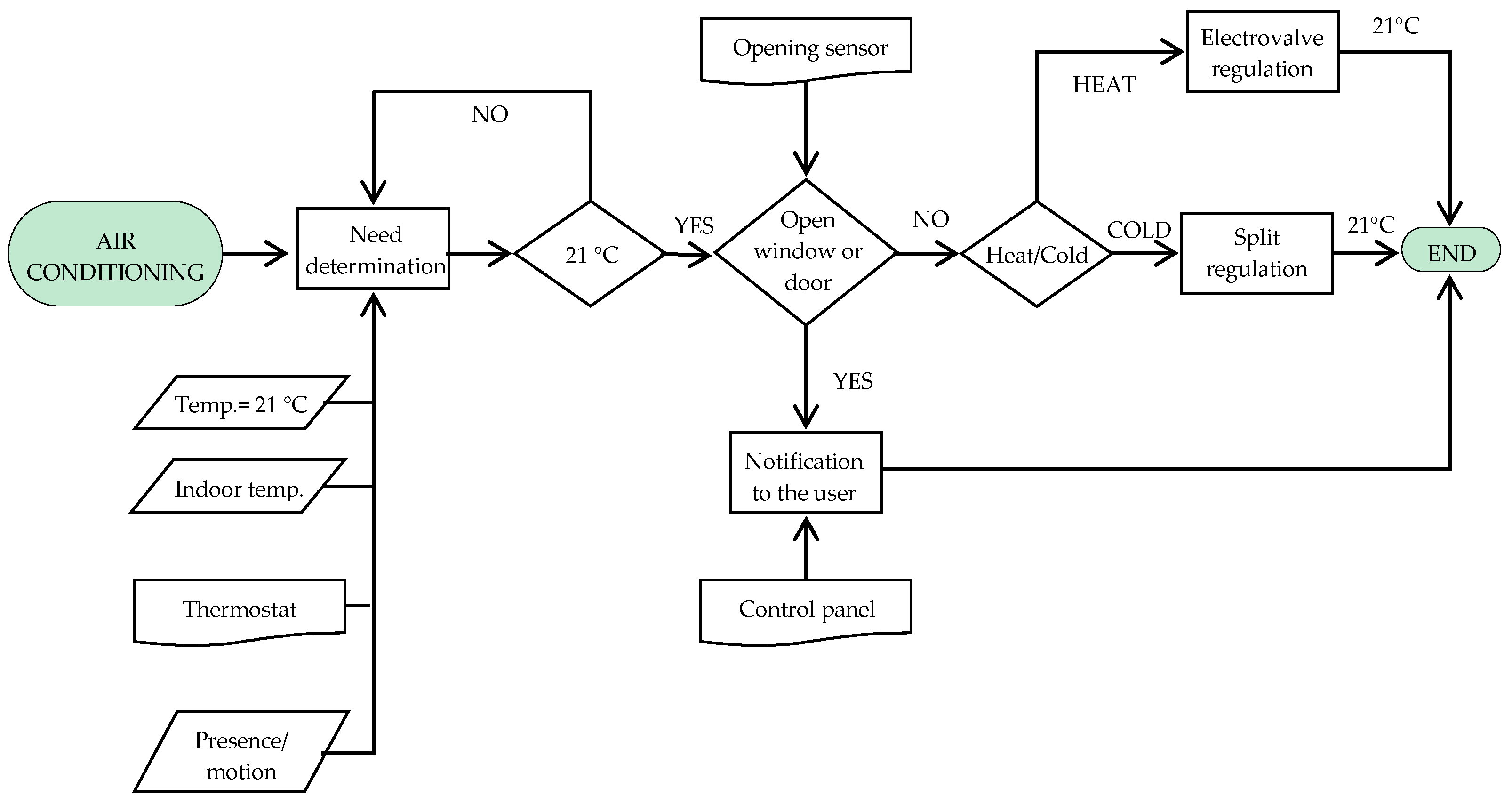
Figure 2.
Lighting functioning flow chart.

Figure 3.
Components distribution for basic home automation system.
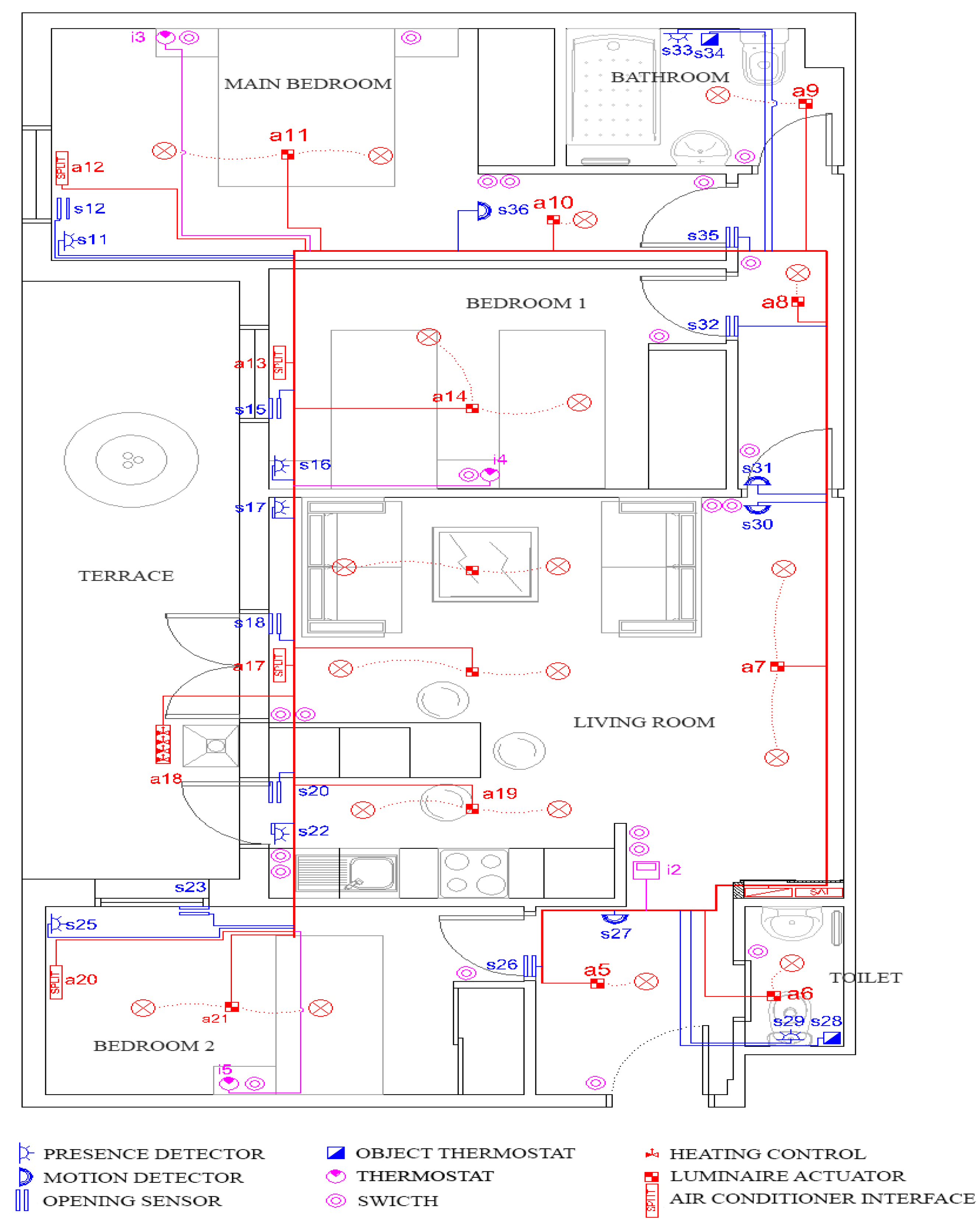
Figure 4.
Flow chart of technical alarms subsystem functioning in case of fire emergency.
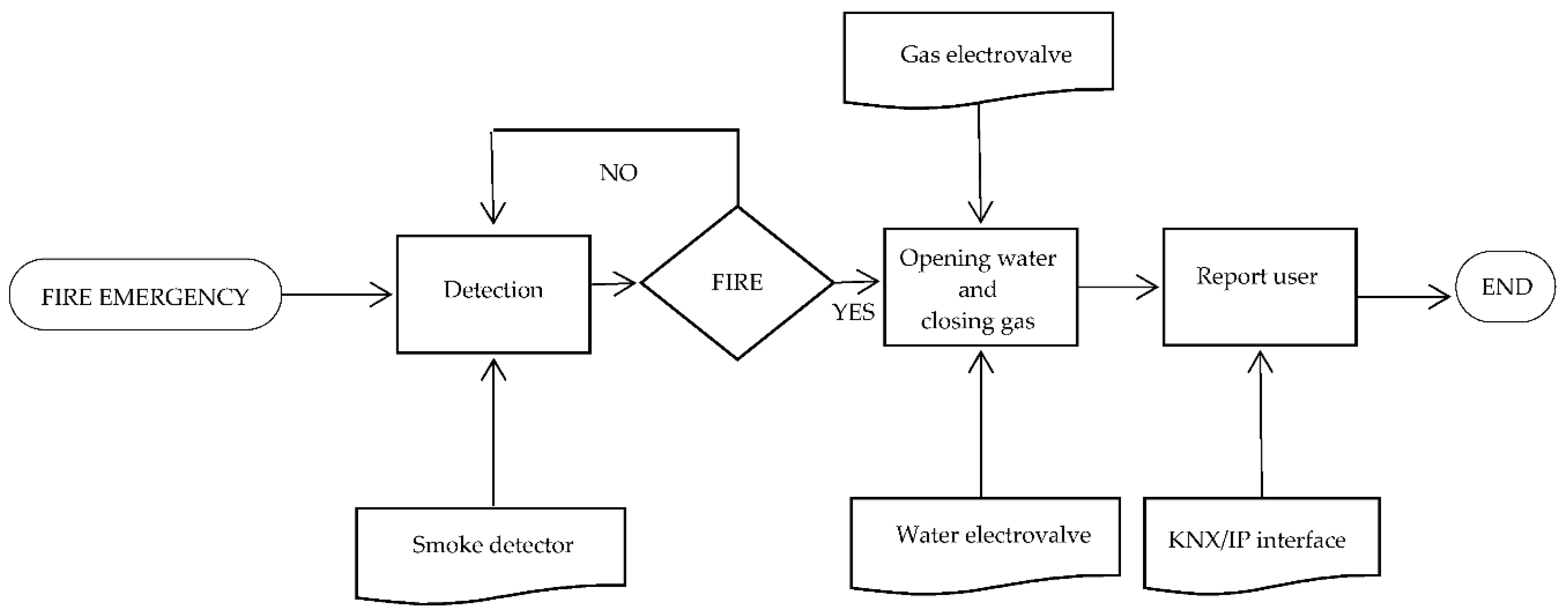
Figure 5.
Security subsystem functioning flow chart.

Figure 6.
Comparative study graph concerning to energy savings (lighting and conditioning).
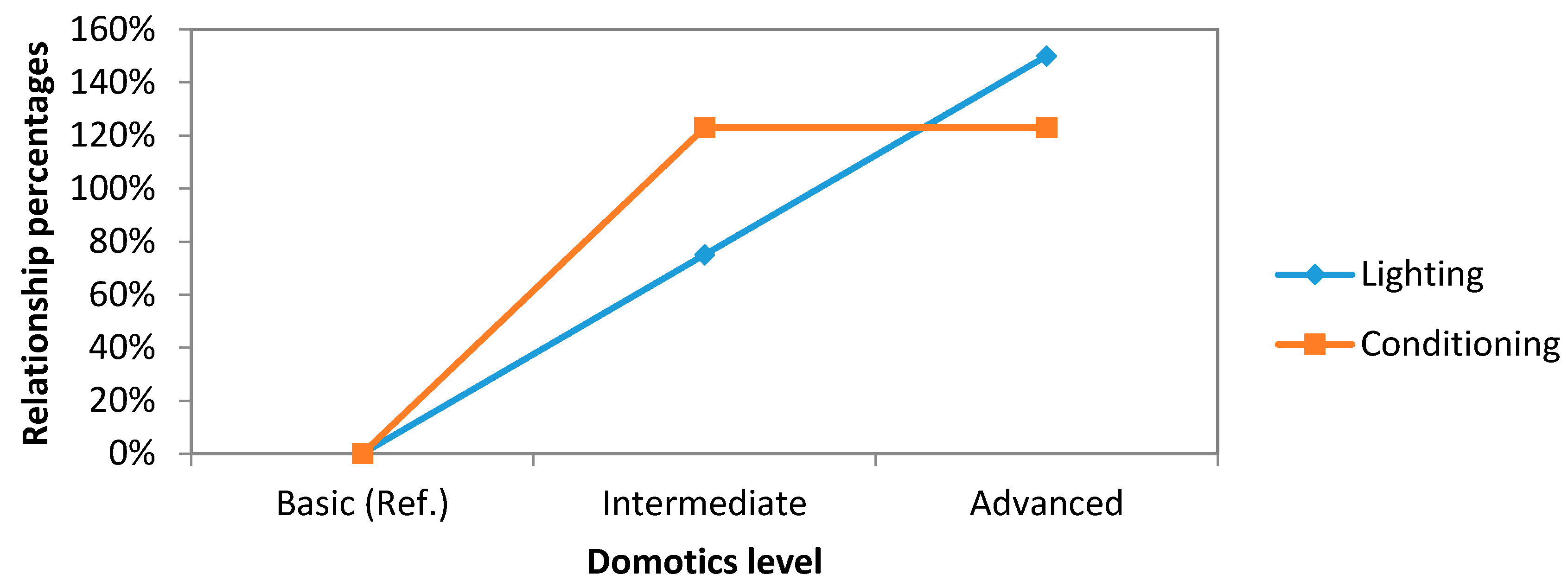
Figure 7.
Comparative study graph concerning to economical savings (lighting and conditioning).

Figure 8.
Comparative study graph concerning to energy savings (electricity and heating).
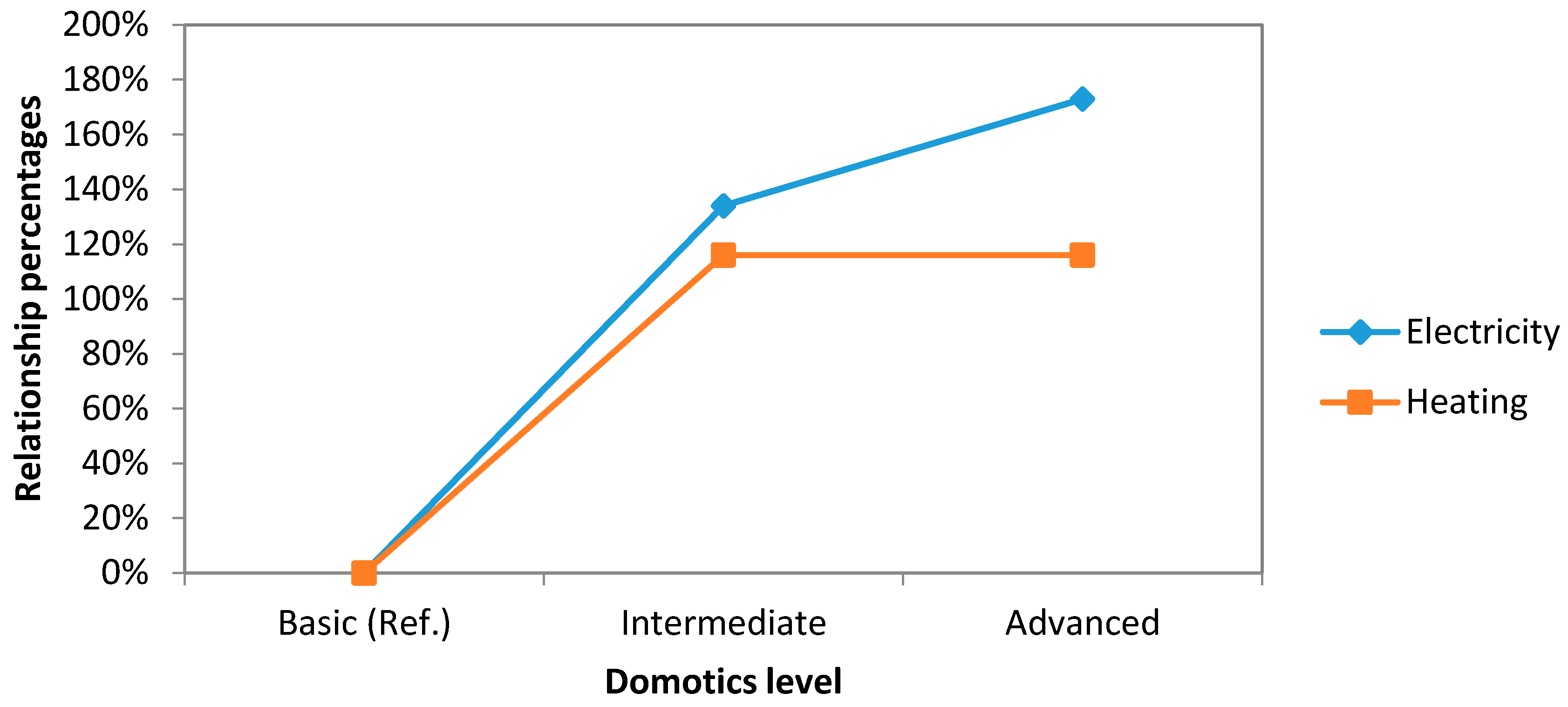
Figure 9.
Comparative study graph concerning to CO2 emissions (electricity and heating).

| Type | Number | Placement Criteria | Total Consumption (mA) | Comments |
|---|---|---|---|---|
| Opening sensor | 8 | 1/window 1/airflow door | - | It requires KNX interface |
| Presence detector | 7 | 1/room | 56 | Installation height = 2.20 m |
| Motion detector | 4 | 1/passing area | 16 | It includes bus coupler and connection terminal |
| Temperature sensor | 6 | 1/room | - | |
| Luminaires actuator | 12 | It depends on the luminaires number | 75 | Binary input to dry contacts connection or conventional push button |
| Heating electrovalve | 6 | 1/room | 5.2 | |
| Split control interface | 4 | 1/split | - | Bidirectional KNX gateway—Air conditioners |
| Type | Comments |
|---|---|
| Opening sensor: KNX.CAGS142 | When detecting the opening or closing of a window or door, a notification is sent to the control panel, which disables or activates air conditioning systems. |
| Presence detector: MTN630819 | It covers an 8-m perimeter and is installed at a height of 2.2 m. It has a detection angle of 360 degrees. |
| Motion detector: MTN631719 | It incorporates a light meter, a bus coupler and a terminal connection. It sends a signal to the control panel to turn the lights on or off depending on whether it detects the presence of someone or not. |
| Indoor temperature sensor: MTN6221-0319 | It determines the temperature and sends it via bus to the logic module by activating the air conditioning until the temperature reaches 21 degrees (temperature setpoint). This activation also depends on the presence of users in the room. |
| Power Meter: MTN6600-0603 | It can monitor up to three channels up to 3680 kW (total 3 × 3680 = 11,040 kW). Transmits data over the bus to the data logger. For its channels, it was reserved: one for air conditioning, one for lights and outlets and the last one for kitchen items. |
| External light sensor: MTN663991 | Brightness and temperature are recorded by it. It communicates with the blind actuator, upping them if it exceeds 300 lux outside. Taking advantage of its temperature meter, it also communicates with heating and air conditioning to get the temperature to the setpoint (21 degrees). |
| Outdoor motion detector: MTN632519 | It is prepared to be installed outside. Detecting the presence of people outside to control external lighting. |
| Temperature probes: MTN616790 | They have been connected to up to four probes to a thermostat to improve the reading. It is installed at different points and at different heights to observe the homogenization temperature on the rooms. |
| Number of Devices Connected to the Bus | 48 | Lines (Meters of Wire) | 1 (101) |
| Combined Consumption (mA) | 168.20 | Power Supply | 1 × 320 mA |
| Line Couplers | 0 (Only one line) | External Communication | No |
| Control Device | Control panel | UPS | No |
| UPS Battery | - | Energy Self-Sufficiency | - |
| Type | Number | Placement Criteria | Total Consumption (mA) | Comments |
|---|---|---|---|---|
| Electric meter | 1 | 1/flat | 12.5 | Max. 11,040 W (3 × 3680 W) |
| Light and temperature sensor | 1 | 1/terrace | 6.25 | Installation to measure light (specular reflection) |
| Binary-railed actuator for current measurement | 1 | 1/kitchen | 16 | Binary input for connection to dry contacts or traditional switches |
| Blinds | 5 | 1/window | 17.5 | |
| Automatic water recirculation system | 1/3 | 1 impulsion module and 1 return module/wet area | 8 | Patent [24] |
| Number of Devices Connected to the Bus | 60 | Lines (Meters of Wire) | 1 (101) |
| Combined Consumption (mA) | 262.45 | Power Supply | 1 × 320 mA |
| Line Couplers | 0 (Only one line) | External Communication | KNX/IP Gateway |
| Control Device | Control panel | UPS | No |
| UPS Battery | - | Energy Self-Sufficiency | - |
| Type | Number | Placement Criteria | Total Consumption (mA) | Comments |
|---|---|---|---|---|
| Outdoors motion detector | 1 | 1/terrace | 13 | |
| Temperature sensor | 16 | 4/room | - | Two sensors at each measuring point, at heights and just above the floor |
| Binary actuator for lights | 1 | 1/terrace | 13 | |
| KNX-DALI gateway | 1 | 1/flat | 5 | Inside a cabinet |
| Electronic ballast | 7 | 1/room with dimmable lights | 0 | Substitute the binary actuators |
| Background music/Communication system | 1 | 1/flat | 5 | Includes iPod Nano to save pre-recorded messages |
| Number of Devices Connected to the Bus | 73 | Lines (Meters of Wire) | 2 (101) |
| Combined Consumption (mA) | 277.45 | Power Supply | 1 × 640 mA 2 × 320 mA |
| Line Couplers | 2 | External Communication | KNX/IP Gateway |
| Control Device | Control panel | UPS | Yes |
| UPS Battery | 7.80 Ah | Energy Self-Sufficiency | 28 h |
| Basic | Intermediate | Advanced | |
|---|---|---|---|
| KNX/IP interface | No | Yes | Yes |
| UPS Battery | No | No | Yes |
| Area power supply | No | No | Yes |
| Line couplers | No | No | Yes |
| Type | Number | Placement Criteria | Total Consumption (mA) | Comments |
|---|---|---|---|---|
| Flood sensor | 1/3 | 1 central device and 1/wet area | 65 | |
| Optical smoke detector | 6 | 1/bedroom, 1 over each sofa and 1/kitchen | 2 | |
| Gas detector for detection of methane | 1 | 1 next to the boiler | 132 | |
| Binary electrovalve to water pipe | 3 | 1/wet area | 6 | Supply from mains. It requires KNX interface |
| Binary electrovalve to gas pipeline | 1 | 1 at the boiler | 2 | It requires KNX interface |
| Number of Devices Connected to the Bus | 18 | Lines (Meters of Wire) | 1 (45) |
| Combined Consumption (mA) | 265.58 | Power Supply | 1 × 320 mA |
| Line Couplers | 0 | External Communication | KNX/IP Gateway |
| Control Device | Logic module | UPS | Yes |
| UPS Battery | 7.80 Ah | Energy Self-Sufficiency | 29 h |
| Basic | Intermediate | Advanced | |
|---|---|---|---|
| KNX/IP interface | No | Yes | Yes |
| UPS Battery | No | No | Yes |
| Area power supply | No | No | Yes |
| Line couplers | No | No | Yes |
| Opening sensor | Yes | Yes | Yes |
| Presence sensor | Yes | Yes | Yes |
| Exit button | No | Yes | Yes |
| Type | Number | Placement Criteria | Total Consumption (mA) | Comments |
|---|---|---|---|---|
| Opening sensor | 5 | 1/outer door or outer window | 0 | |
| Break sensor | 5 | 1/outer door or outer window | 50 | |
| Presence sensor | 5 | 1/outer room | 0 | Synergy with basic system |
| System | Main features | Resource Savings | % Energy Savings | |||
|---|---|---|---|---|---|---|
| Lighting Management (kWh) | Basic |
| 6.80 | 19.88 | ||
| Intermediate |
| 11.90 | 34.79 | |||
| Advanced |
| 17.01 | 50 | |||
| Heating | Air Conditioning | Heating | Air Conditioning | |||
| Air Conditioning Management (kWh) | Basic |
| 147.02 | 64.58 | 17.82 | 14.35 |
| Intermediate |
| 317.05 | 154.17 | 38.43 | 34.26 | |
| Advanced |
| 317.05 | 154.17 | 38.43 | 34.26 | |
| System | Main Features | Resource Savings (L/Day) | % Energy Savings | |
|---|---|---|---|---|
| Water Resources Management | SARAP [24] | Automatic water recirculation system | 180 | 33.84 |
| System | Total | Lighting | Air Conditioning | Power Term | Water Resources | Monthly Savings | Annual Savings |
|---|---|---|---|---|---|---|---|
| Basic | 9613.86 | 1.25 | 23.78 | - | - | 25.03 | 300.40 |
| Intermediate | 13,737.46 | 1.46 | 42.72 | 4.56 | 7.40 | 56.14 | 673.68 |
| Advanced | 24,533.66 | 2.28 | 42.72 | 4.56 | 7.40 | 56.96 | 683.52 |
| Technical Alarms | 3871.83 | - | - | - | - | - | |
| Security | 3548.31 | - | - | - | - | - |
| Basic | Intermediate | Advanced | |
|---|---|---|---|
| Payback Period (Years and Months) | 32 years | 20 years and 5 months | 38 years and 4 months |
| System | Conversion Factor (gr CO2/kWh) | Energy Savings (kWh) | Reduction of CO2 Emissions (kg/Month) | |
|---|---|---|---|---|
| Electricity | Basic | 645 | 71.38 | 46.04 |
| Intermediate | 166.07 | 107.12 | ||
| Advanced | 195.4 | 126.03 | ||
| Gas | Basic | 204 | 147.02 | 29.99 |
| Intermediate | 317.05 | 64.68 | ||
| Advanced | 339.32 | 69.22 |
| System | Madrid (%) (Continental Zone) | Barcelona (%) (Mediterranean Zone) | A Coruña (%) (Atlantic Zone) | |
|---|---|---|---|---|
| Lighting management | Basic | 19.88 | 51.49 | 27.43 |
| Intermediate | 34.79 | 70.11 | 48.01 | |
| Advanced | 50.00 | 85.50 | 69.01 | |
| Heating | Basic | 17.82 | 9.91 | 9.02 |
| Intermediate | 38.43 | 21.35 | 19.41 | |
| Advanced | 38.43 | 21.35 | 19.41 | |
| Air conditioning | Basic | 14.35 | 15.78 | 5.35 |
| Intermediate | 34.26 | 37.69 | 12.77 | |
| Advanced | 34.26 | 37.69 | 12.77 | |
| Water resources | Basic | 33.84 | 30.21 | 31.05 |
| Intermediate | ||||
| Advanced |
© 2016 by the authors; licensee MDPI, Basel, Switzerland. This article is an open access article distributed under the terms and conditions of the Creative Commons Attribution (CC-BY) license (http://creativecommons.org/licenses/by/4.0/).
Share and Cite
MDPI and ACS Style
Morón, C.; Payán, A.; García, A.; Bosquet, F. Domotics Project Housing Block. Sensors 2016, 16, 741. https://doi.org/10.3390/s16050741
AMA Style
Morón C, Payán A, García A, Bosquet F. Domotics Project Housing Block. Sensors. 2016; 16(5):741. https://doi.org/10.3390/s16050741
Chicago/Turabian StyleMorón, Carlos, Alejandro Payán, Alfonso García, and Francisco Bosquet. 2016. "Domotics Project Housing Block" Sensors 16, no. 5: 741. https://doi.org/10.3390/s16050741
Note that from the first issue of 2016, this journal uses article numbers instead of page numbers. See further details here.