Article

Design and Sensitivity Analysis Simulation of a Novel 3D Force Sensor Based on a Parallel Mechanism

by
Eileen Chih-Ying Yang
Advanced Institute of Manufacturing with High-tech Innovations, and Department of Mechanical Engineering, National Chung Cheng University, Chia-Yi 621, Taiwan
Sensors 2016, 16(12), 2147; https://doi.org/10.3390/s16122147
Submission received: 16 September 2016 / Revised: 29 November 2016 / Accepted: 13 December 2016 / Published: 16 December 2016
(This article belongs to the Section Physical Sensors)

Abstract

:
Automated force measurement is one of the most important technologies in realizing intelligent automation systems. However, while many methods are available for micro-force sensing, measuring large three-dimensional (3D) forces and loads remains a significant challenge. Accordingly, the present study proposes a novel 3D force sensor based on a parallel mechanism. The transformation function and sensitivity index of the proposed sensor are analytically derived. The simulation results show that the sensor has a larger effective measuring capability than traditional force sensors. Moreover, the sensor has a greater measurement sensitivity for horizontal forces than for vertical forces over most of the measurable force region. In other words, compared to traditional force sensors, the proposed sensor is more sensitive to shear forces than normal forces.

1. Introduction

Automated force measurement is a critical requirement for intelligent automation systems. Many one-dimensional (1D) force sensors based on micro-electromechanical systems (MEMS) techniques have been developed in recent years, including strain gauge-based force sensors, piezoresistive force sensors, capacitive force sensors, piezomagnetic force sensors, optical force sensors, and electroactive force sensors [1]. Furthermore, various researchers have demonstrated multi-dimensional force/torque sensors using multi-component structures [2,3]. Vázsonyi et al. [4] presented a three-dimensional (3D) sensor for detecting normal and shear forces incorporating a rectangular rod and an etched membrane. Sieber et al. [5] proposed a triaxial force sensing device consisting of a MEMS sensor attached to a three degree-of-freedom (3DOF) nanomanipulator. Cappelleri et al. [6] developed a vision-based sensor for micro-robotic systems consisting of a CCD camera and an elastic mechanism with a known force-deflection response. Kim [7] constructed a 3D force sensor for intelligent grippers based on five parallel plate-beams.
In general, the methods described above are designed for micro-force detection. However, in many engineering fields, e.g., shipbuilding, aerospace, and aviation, the ability to measure heavy 3D forces and loads remains a significant challenge. This problem is generally addressed using some form of parallel sensing mechanism since such structures have the advantages of stability, a high loading capability, zero error accumulation, and a high accuracy [8,9,10,11,12,13,14,15,16]. Dwarakanath and Venkatesh [17] proposed a simple “joint-less” parallel mechanism for force-torque sensing, in which the degrees of freedom of the structure were constrained by linearly-independent line constraints. Ranganath et al. [18] designed a force/torque sensor based on a Stewart platform with a near-singular configuration and optimized the structure in such a way as to achieve a well-conditioned transformation between the input and output forces. Liu and Tzo [19] investigated the measurement isotropy and sensitivity of a six-component force sensor consisting of four identical T-shaped bars. Yao et al. [20] conducted a theoretical and experimental investigation into the isotropy performance of a pre-stressed force sensor based on a Stewart platform. In later studies, the same group proposed a spatially isotropic configuration for the sensor [21] and a task-oriented method for its design [22]. However, in force/torque sensors based on a Stewart platform, the sensing mechanisms attached to the limbs are easily damaged under heavy loads. Thus, Liang and Wang [23] developed a humanoid robot ankle and integrated a force/torque sensor based on an orientation parallel kinematic mechanism. Lu et al. [24] designed and analyzed a novel force/torque sensor for a hybrid hand with three fingers.
In many of the methods described above, the effective measuring capability, or resolution, is deliberately sacrificed to a certain extent in order to increase the number of measurable force/torque components. However, some applications require more sensitivity to shear forces than normal forces and high-resolution measurement of only the exerted force (i.e., not the torque). For example, those aimed at measuring the 3D ground reaction force (GRF) in a human’s gait, since shear forces of GRF will be the critical effect that makes the human move forward, fall laterally, or be unbalanced during walking or running motions [25]. For another example, capturing the exerted shear force with precision is even more important than the normal (axial) force in measuring with the force sensor of articulated arm coordinate measuring machines (AACMMs) [26] or coordinate-measuring arms (CMAs) [27]. Accordingly, the present study proposes a novel 3D force sensor which measures only the 3D force. The sensor is based on a parallel mechanism. Thus, the transformation between the exerted 3D force and the mechanism posture can be established from a position analysis and the principles of static equilibrium. However, in a parallel mechanism, a particular equilibrium position of the end effecter is not necessarily associated with a unique solution of the posture. Accordingly, in the proposed sensor, the parallel structure comprises three pairs of parallel links such that each equilibrium position of the end effecter is constrained to a unique posture solution. Moreover, the torque effect acting on the end effecter is eliminated through the use of ball-socket joints in the parallel links. Finally, a constraint is added to the position analysis to ensure that the solution is continuously transformed from the initial posture of the sensor. Consequently, the magnitude of the applied 3D force can be determined by measuring the associated rotational angles of the three parallel links using rotary encoders.
The remainder of this paper is organized as follows: Section 2 describes the basic structure of the proposed 3D force sensor; Section 3 derives the transformation function and sensitivity index of the sensor; Section 4 presents and discusses the simulation results for the measurement capability and sensitivity of the sensor; and, finally, Section 5 presents some brief concluding remarks.

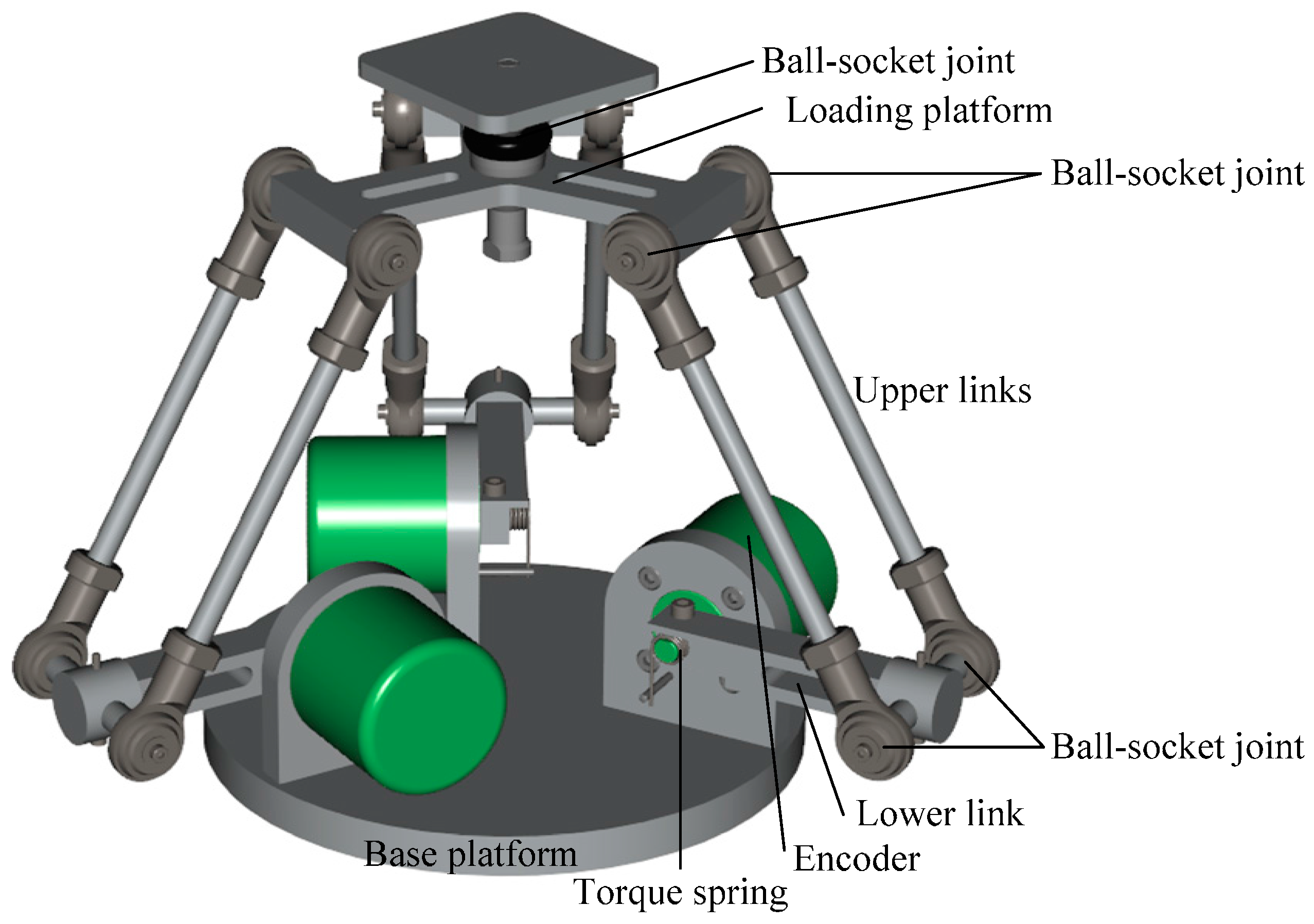
2. Mechanism of 3D Force Sensor

Figure 1 illustrates the novel 3D force sensor proposed in this study. As shown, the sensor consists mainly of a base platform, three linkages, and a loading platform. Each linkage comprises a pair of upper links and a single lower link, where the upper and lower links are connected by ball-socket joints. The two upper links are parallel to one another and are connected to the loading platform by a further set of ball-socket joints. One rotational degree of freedom exists between the lower link and the base platform, i.e., the torque spring and encoder are actuated by the rotational motion of the lower link. The torque spring is implemented using a leaf circular spring with a high and constant spring stiffness coefficient.
Let B0 and P0 be the center points of the base and loading platforms, respectively; and Bi, Ji, and Pi be the connection points between the platforms and links, where the suffix i denotes the i-th linkage, i = 1, 2, 3 (see Figure 2). In analyzing the position/posture of the sensor structure, the angular position of rotational joint Bi is denoted as θi, while the two rotational angles of the ball-socket joint Ji are denoted as αi and βi, respectively. Due to the configuration of the sensor, the rotational axes of αi and θi are parallel to one another and orthogonal to that of βi. As a result, the loading platform remains parallel to the base platform at all times and can move with three translational degrees of freedom.

3. Transformation Function and Sensitivity Index

Based on the definition of points B0, P0, Bi, Ji, and Pi for the i-th linkage, i = 1, 2, 3 (see Figure 2), let the following parameters be introduced: (1) γi: the angular position from X0 to vector B0Bi, where γi is equal to 0°, 120°, and −120° for i = 1, 2, 3, respectively, due to the triangular symmetrical arrangement of the three linkages; (2) rB and rP: the lengths of vectors B0Bi and P0Pi, respectively; and (3) LD and LU: the lengths of the lower and upper links, respectively. Based on the geometric relations between the links, and the constraints imposed by the parallel configuration of the sensor structure, the position of P0 can be determined mathematically as:
P 0 i = [ cos γ i ( r B + L D cos θ i + L U cos ( θ i + α i ) cos β i r P ) L U sin γ i sin β i sin γ i ( r B + L D cos θ i + L U cos ( θ i + α i ) cos β i r P ) + L U cos γ i sin β i L D sin θ i + L U sin ( θ i + α i ) cos β i ]
Due to the parallel configuration, the same solution is obtained for each position vector P0i, i = 1, 2, 3, i.e., P01 = P02 = P03 = [Px Py Pz]T. Thus, the nine variables (θi, αi and βi for i = 1, 2, 3) can be solved as:
θ i = cos 1 ( Μ i Κ i 2 + ρ i 2 ) + λ i
β i = sin 1 ( P x sin γ i + P y cos γ i L U )
α i = cos 1 ( ( P x cos γ i + P y sin γ i r B + r P ) 2 + ( P x sin γ i + P y cos γ i ) 2 + P z 2 L D 2 L U 2 2 L D L U cos β i )
where: Κ i Κ i 2 + ρ i 2 = cos λ i , Κ i = 2 ( r B r P ) L D + 2 P x cos γ i L D + 2 P y sin γ i L D , ρ i = 2 P z L D , Μ i = 2 P x cos γ i ( r B r P ) 2 P y sin γ i ( r B r P ) + P x 2 + P y 2 + P z 2 + L D 2 L U 2 + ( r B r P ) 2 .
To establish the relation between the input force and the sensor posture, let the following vectors be introduced for each linkage: ΔsP,Pi, ΔsU,Pi, ΔsU,Ji, ΔsD,Ji, and ΔsD,Bi, where each vector represents the vector from the mass center of the link to the connection point (see Figure 2), and can be formulated in terms of the link parameters and the posture variables, θi, αi, and βi. Assuming that the mass centers are located at the mid-point positions of the links, the five vectors can be derived as:
Δ s P , P i = r P [ cos γ i sin γ i 0 ]
Δ s U , P i = Δ s U , J i = L U 2 [ cos γ i cos ( θ i + α i ) cos β i sin γ i sin β i sin γ i cos ( θ i + α i ) cos β i + cos γ i sin β i sin ( θ i + α i ) cos β i ]
Δ s D , J i = Δ s D , B i = L D 2 [ cos γ i cos θ i sin γ i cos θ i sin θ i ]
In accordance with the principles of static equilibrium, the force acting on the loading platform can be derived as:
f x + i = 1 3 f P i , x = 0 ,   f y + i = 1 3 f P i , y = 0 ,   f z + i = 1 3 f P i , z + m P g 0 = 0
i = 1 3 ( r P sin γ i f P i , z ) = 0 ,   i = 1 3 ( r P cos γ i f P i , z ) = 0 ,   i = 1 3 ( r P ( cos γ i f P i , x + sin γ i f P i , y ) ) = 0
where mP is the mass of the loading platform; g is the gravity vector, i.e., g = [0 0 g0]T m/s2; fload is the 3 × 1 force vector applied to the loading platform along the X-, Y-, and Z-directions, respectively, i.e., fload = [fx fy fz]T; and fPi is the force acting at connection point Pi and is denoted as fPi = [fPi,x fPi,y fPi,z]T. The torque acting at point Bi, which causes rotational motion of the torque spring and encoder, can be derived as:
n B i = ( Δ s U , P i Δ s U , J i + Δ s D , J i Δ s D , B i ) × f P i ( Δ s U , J i + Δ s D , J i Δ s D , B i ) × m U i g + Δ s D , B i × m D i g
where mP, mUi, and mDi are the masses of the loading platform, upper links, and lower link of the i-th linkage, respectively. The torque along the rotational axis of θi is given by:
( n B i ) T Z D i = K T Δ θ i
where ZDi is the rotational axis of θi, KT is the stiffness coefficient of the torque spring, and Δθi is the rotational angle measured by the encoder. The rotational angles of the three encoders can be used to estimate the 3D loading force by solving Equations (8)–(11), and can be expressed as the following nonlinear function of the exerted force:
Δ θ i = G i ( f x , f y , f z )   for   1 i 3
In general, the sensitivity of a transducer is evaluated as the rate of variation of the output relative to the input. However, this traditional definition cannot be applied to the force sensor proposed in the present study since the transformation function of the proposed sensor has a nonlinear form and the system has multiple (rather than single) inputs and outputs (i.e., the system is a multi-input-multi-output (MIMO) system). Accordingly, the sensitivity of the proposed sensor is described instead using a Jacobian matrix J ^ , in which the net-force dependent problem is resolved by dividing the exerted forces by the respective Euclidean norms. In other words, the components of J ^ appearing in the i-th row are the derivatives of the nonlinear function Gi with respect to the exerted force, fload, i.e.,
J ^ i = G i f load   for   1 i 3
The measurement sensitivities of the sensor for exerted forces in the X-, Y-, and Z-directions (referred to as the X-, Y-, and Z-sensitivities, respectively, and denoted as νx, νy, and νz) are defined as the Euclidean norms of each column in J ^ , i.e.,
J ^ = [ J ^ x J ^ y J ^ z ]
ν y = J ^ y
Meanwhile, the variation of the sensor sensitivity for forces exerted in different directions is defined as the sensitivity diversity index (vd) and is derived in accordance with the spectral norm of the Jacobian matrix J ^ and its inverse J ^ 1 as follows:
ν d = J ^ 2 ( J ^ 1 2 ) 1 = λ max λ min
where λmax and λmin are the largest and smallest eigenvalues of ( J ^ * J ^ ) , respectively, and J ^ * is the conjugate transpose of J ^ .

4. Simulation Results and Discussion

The formulations presented in the previous section for the transfer function and sensitivity of the proposed 3D force sensor were implemented in a MATLAB (MathWorks, Inc., Natick, MA, USA) program. Simulations were then performed to investigate the force measuring capability of the proposed device and its measurement sensitivity with respect to the forces exerted in the X-, Y-, and Z-directions.

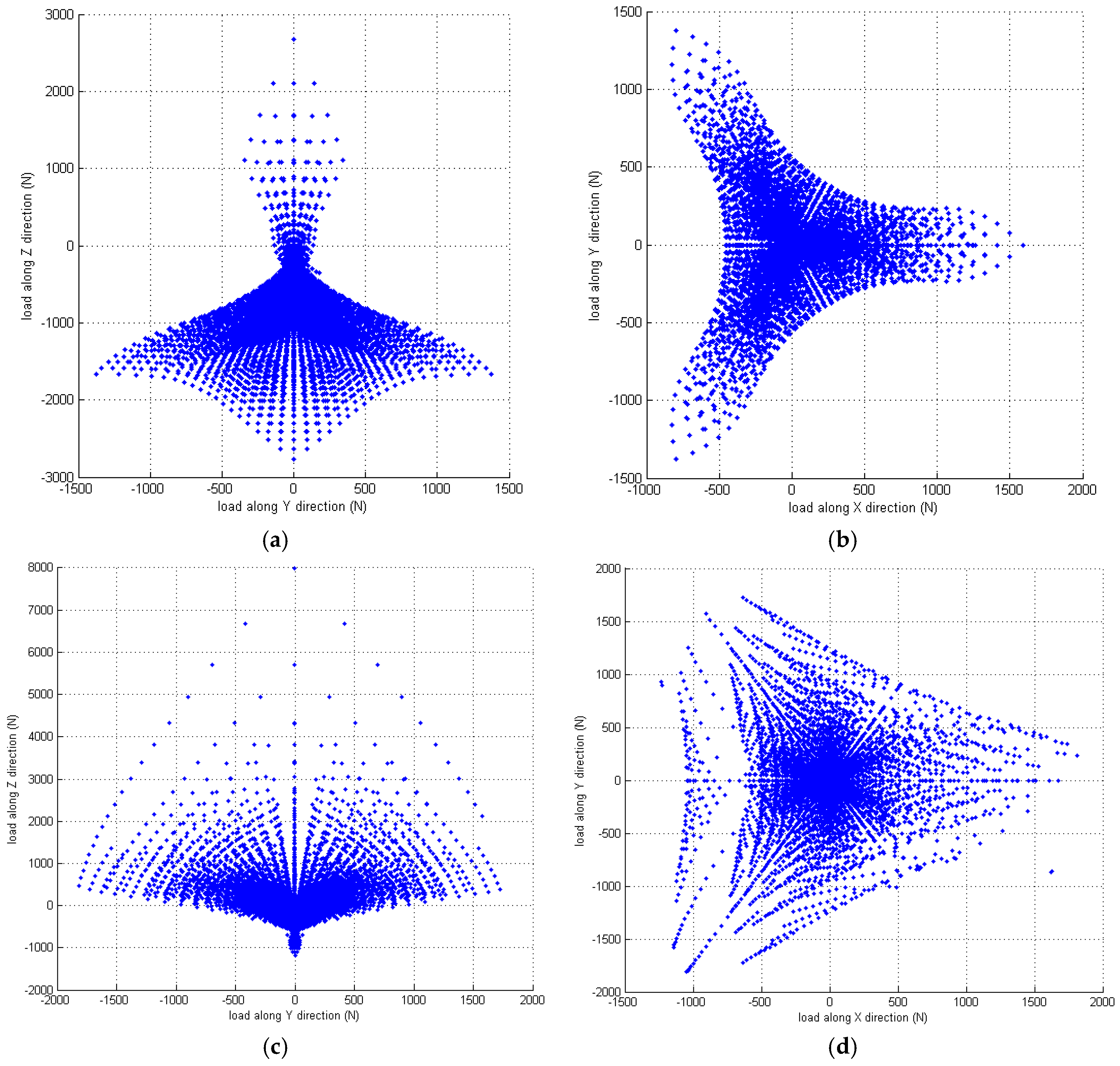
4.1. Effective Measuring Capability

From the previous investigation [28], the parallel mechanism will have the maximum workspace while the lengths of the upper links are twice as long as the lower links. Thus, in evaluating the measuring capability of the sensor, the link lengths were set as rB = rP = 45 mm, LD = 60 mm and LU = 120 mm, and these links are assumed as rigid bodies. In addition, the stiffness coefficient of the torque spring was set as Kspring = 0.7 Nm/deg, while the initial angular position of the rotational joint Bi in the absence of an applied torque was set as θi = 45°. Finally, the working range of the rotational angle, Δθi, was assumed to be 90°, i.e., from −55° to 35°.
Figure 3 shows the corresponding results obtained for the effective measuring capability of the sensor in the X-, Y-, and Z-directions. It is seen that the distribution of the measurable 3D force has a triangular symmetrical characteristic, which mimics that of the sensor mechanism configuration.

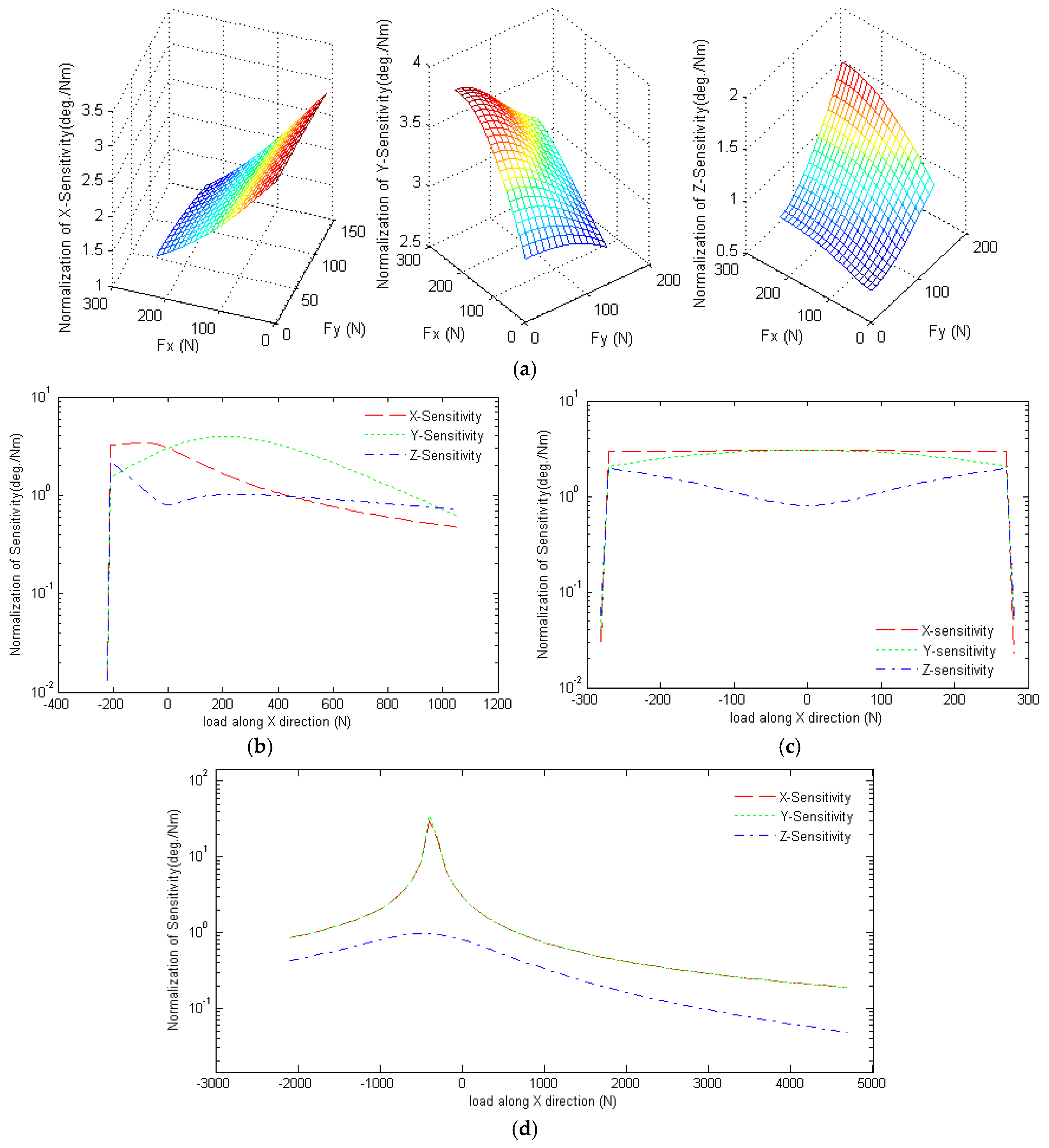
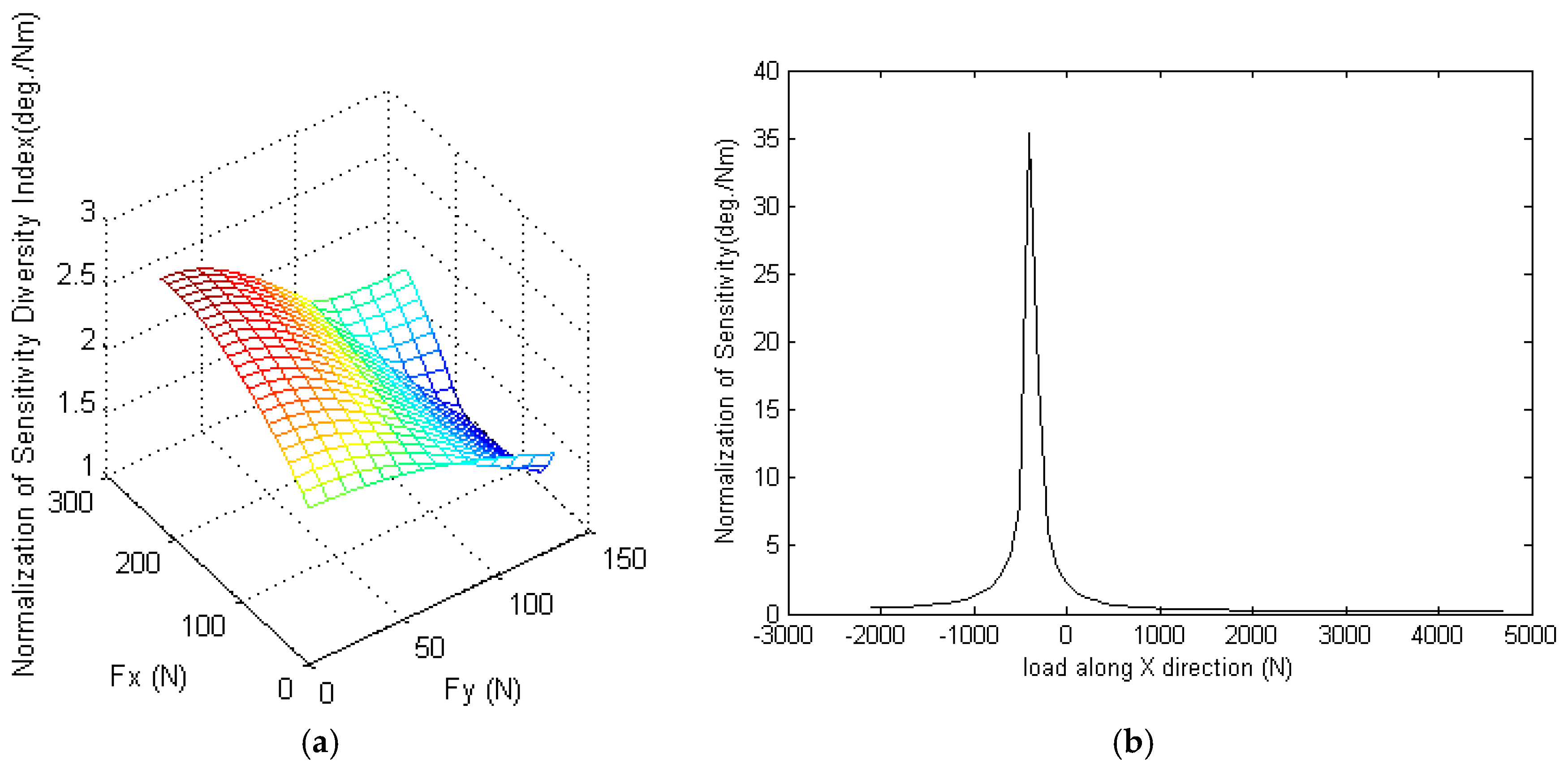
4.2. Sensitivity and Sensitivity Diversity Index

Since the sensitivities are directionally proportional to the lever arm, in accordance with the deriving formulation of sensitivities in Equations (10)–(15), we normalize the sensitivities by dividing the length of the lower link to decouple the size effect. Figure 4 shows the normalization of the X-, Y- and Z-sensitivities of the proposed sensor for various input load conditions. As described in Section 3, the inputs and outputs of the sensor are related via a nonlinear transfer function and, hence, the sensitivity depends on the static equilibrium posture. Based on the structure of the 3D force sensor, the equivalent lever arm of the horizontal force (i.e., the force acting along the X- or Y-direction) is approximately equal to the sum of the vertical components of vectors B i J i and J i P i . Similarly, the equivalent lever arm of the vertical force (i.e., the force acting along the Z-direction) is approximately equal to the difference in the horizontal components of the vector B i J i and J i P i . For most static equilibrium postures of the sensor, the equivalent lever arm of the horizontal exerted force is larger than that of the vertical exerted force. Moreover, the higher sensitivity is caused by the higher effective driving torque, which varies in proportion to the equivalent lever arm. Therefore, the device has a greater measuring sensitivity for horizontal forces than for vertical forces, other than in the central triangular region, i.e., fx > 450 N (see Figure 4). In other words, the sensor is more sensitive to shear forces than normal forces over most of the measurable force region. In this regard, the sensor differs from traditional force sensors, which generally exhibit greater a sensitivity toward forces acting in the normal direction.
The greater sensitivity of the proposed sensor to shear forces is due to the greater efficacy of horizontal forces in exciting the rotational angle of the encoders. When the force sensor is subject to a vertical force only, the postures of the three linkages are the same as those under static equilibrium conditions. Given such a symmetrical posture, the transmission angles of the horizontal force are greater than those of the vertical force. Therefore, the X- and Y-sensitivities of the sensor are greater than the Z-sensitivity (see Figure 4d).
Figure 5 shows the simulation results for the normalization of the sensitivity diversity index νd of the sensor. It is seen that normalization of νd has a value of less than 2.943 deg/Nm given the application of a horizontal force. However, the normalization of the sensitivity diversity index has a value of up to 35.3 deg/Nm under a vertical force due to the near-orthogonal transmission angles of the applied force along the X- and Y-directions.

4.3. Design Variable Analysis

In order to discuss the design variables, we define the same parameters as the above example, i.e., rB = rP = 45 mm, LD = 60 mm, LU = 120 mm, Kspring = 0.7 Nm/deg, and links are rigid bodies. However, the initial angular position and stiffness coefficient of the torque spring are separately changed to find their effect. For the effect of the angular position of the torque spring, it is assumed that the rotational angle of the links is limited to the range of −10° to 90° (i.e., −10 deg ≤ θi ≤ 90 deg) in designing the 3D force sensor. In addition, the rotational angles of the encoders, Δθi, are assumed to be positive under the effects of a tensile exerted force (i.e., fz > 0 N), and negative under a compressive exerted force (i.e., fz < 0 N). Figure 6 shows the effective 3D force measuring capability of the proposed sensor given initial angular positions of the torque spring equal to 60° and 20°, respectively. From the simulation results, we can find that the effective measuring capability of the sensor for a tensile force increases as the initial angular position of the torque spring decreases, while that for a compressive force varies proportionally with the initial angular position of the torque spring. In addition, there is an asymmetrical plot existing at the point of fx = 1628 N and fy = −863.2 N. This may be caused by a numerical analysis error since the point is close to the workspace boundary of the parallel mechanism. The solution of the nonlinear equations would be solved with a different configuration of the force sensor. Thus, it may appear that the measurement error is close to the measurable boundary. Furthermore, we define different stiffness coefficients of the torque spring to find its effect, and Table 1 shows the X-, Y-, and Z-sensitivities of the proposed sensor under horizontal and vertical forces, respectively, given different values of the torque spring stiffness coefficient. From the results, the sensitivities are inversely proportional to the stiffness coefficient, while the direction of the exerted forces are the same with the sensitivity, i.e., X- and Y-sensitivities for horizontal forces, and Z-sensitivity for vertical forces. This is because the larger stiffness would decrease the resolution of the transformation between the force and the angular position.

5. Conclusions

A novel force sensor has been proposed for measuring 3D forces only (i.e., not the torque). The sensor is based on a parallel structure. Analytical expressions have been derived for the transformation function and sensitivity index of the proposed device based on a position analysis and the principles of static equilibrium. The simulation results have shown that the sensor has a greater effective measuring capability than traditional force sensors. In addition, the sensitivity of the proposed device for exerted horizontal forces is greater than that for exerted vertical forces. In other words, the sensor is more sensitive to shear forces than normal forces and, thus, differs from traditional force sensors, for which the reverse is generally true. Notably, the effective measuring capability of the device for tensile or compressive forces can be tuned by modifying the initial angular position of the torque springs used to activate the encoders. In addition, the sensitivity of the device can be adjusted by using torque springs with a different stiffness coefficient.
The previous studies about force sensors are applied to the structural design to decouple the horizontal and vertical forces, and the forces and torques can be divided into component forces measured by the inserted force sensor. Nevertheless, in the proposed force sensor, we estimate the exerted force by measuring three angular positions caused by three torques which are equal to the exerted force multiplied by the lever arm. In addition, the equivalent lever arm of the horizontal force is approximately equal to the sum of the vertical components of two links, and the equivalent lever arm of the vertical force is approximately equal to the difference in the horizontal components of two links. The lever arm of the horizontal force is larger than that of the vertical force. Thus, the horizontal (shear) force will be more sensitive than the vertical (normal) force.
Furthermore, the critical factors which caused the different performances between simulations and the physical prototype are assumptions of rigid links and clearanceless joints. Nevertheless, the effect of the flexible links and joint clearance can be estimated via finite element analysis (FEM) [29], and the design of the non-spherical ball joint or the optimization links can be adopted to improve the loading performance [30]. In addition, it is rare for the spring to have a constant stiffness coefficient in all extension/compression ranges, and the relationship of the stiffness coefficient and extension/compression length needs to be distinguished. In further research, these effects will be considered in simulations to increase the accuracy compared with the actual force sensor prototype. In practice, it is very difficult to isolate the effects of the individual installation variables. However, according to the sensitivity analysis presented in [31], the positioning accuracy of the end effector in parallel manipulators is particularly sensitive to the link length, and the effect of the assembly defect (e.g., lack of parallelism, alignments, etc.) is less sensitive. Thus, the tolerance requirement of link dimension for manufacturing the actual prototype needs to be less than the maximum tolerance Δli/li = 10−3.

Acknowledgments

The authors gratefully acknowledge the financial support provided to this study by the National Science Council of Taiwan under Grant No. NSC 105-2221-E-194-019. In addition, the authors would like to thank the Advanced Institute of Manufacturing for High-Tech Innovations and the Department of Mechanical Engineering at National Chung Cheng University for providing the experimental equipment and facilities used in the course of the study.

Conflicts of Interest

The authors declare no conflict of interest.

References

  1. Wei, Y.; Xu, Q. An overview of micro-force sensing techniques. Sens. Actuators A Phys. 2015, 234, 359–374. [Google Scholar] [CrossRef]
  2. Li, Y.-J.; Zhang, J.; Jia, Z.-Y.; Qian, M.; Li, H. Research on force-sensing element’s spatial arrangement of piezoelectric six-component force/torque sensor. Mech. Syst. Signal Process. 2009, 23, 2687–2698. [Google Scholar] [CrossRef]
  3. Noda, K.; Matsumoto, K.; Shimoyama, I. Stretchable tri-axis force sensor using conductive liquid. Sens. Actuators A Phys. 2014, 215, 123–129. [Google Scholar] [CrossRef]
  4. Vázsonyi, É.; Ádám, M.; Dücső, Cs.; Vízváry, Z.; Tóth, A.L.; Bársony, I. Three-dimensional force sensor by novel alkaline etching technique. Sens. Actuators A Phys. 2005, 123, 620–626. [Google Scholar] [CrossRef]
  5. Sieber, A.; Valdastri, P.; Houston, K.; Eder, C.; Tonet, O.; Menciassi, A.; Dario, P. A novel haptic platform for real time bilateral biomanipulation with a MEMS sensor for triaxial force feedback. Sens. Actuators A Phys. 2008, 142, 19–27. [Google Scholar] [CrossRef]
  6. Cappelleri, D.J.; Pizaaz, G.; Kumar, V. A two dimensional vision-based force sensor for microrobotic applications. Sens. Actuators A Phys. 2011, 171, 340–351. [Google Scholar] [CrossRef]
  7. Kim, G.-S. Development of a three-axis gripper force sensor and the intelligent gripper using it. Sens. Actuators A Phys. 2007, 137, 213–222. [Google Scholar] [CrossRef]
  8. Gaillet, C.R. An isostatic six componenet force and torque sensor. In Proceedings of the 13th International Symposium on Industrial Robots, Chicago, IL, USA, 17–21 April 1983.
  9. Kerr, D.R. Analysis, properties and design of a Stewart-platform transducer. J. Mech. Transm. Autom. Des. 1989, 111, 25–28. [Google Scholar] [CrossRef]
  10. Nguyen, C.C.; Antrazi, S.S.; Zhou, Z.L.; Campbell, C.E. Analysis and experimentation of a Stewart platform-based force/torque sensor. Int. J. Robot. Autom. 1992, 7, 133–140. [Google Scholar]
  11. Ferraresi, C.; Pastorelli, S.; Sorli, N.; Zhmud, M. State and dynamic behavior of a high stiffness Stewart platform-based force/torque sensor. J. Robot. Syst. 1995, 12, 883–893. [Google Scholar] [CrossRef]
  12. Sorli, M.; Pastorelli, S. Six-axis reticulated structure force/torque sensor with adaptable performances. Mechatronics 1995, 5, 585–601. [Google Scholar] [CrossRef]
  13. Dai, J.S.; Kerr, D.R. A six-component contact force measurement device based on the Stewart platform. J. Mech. Eng. Sci. 2000, 214, 687–697. [Google Scholar] [CrossRef]
  14. Dwarakanath, T.A.; Dasgupta, B.; Mruthyunjaya, T.S. Design and development of a Stewart platform based force-torque sensor. Mechatronics 2001, 11, 793–809. [Google Scholar] [CrossRef]
  15. Kang, C.-G. Closed-form force sensing of a 6-axis force transducer based on the Stewart platform. Sens. Actuators A Phys. 2001, 90, 31–37. [Google Scholar] [CrossRef]
  16. Jia, Z.-Y.; Lin, S.; Liu, W. Measurement method of six-axis load sharing based on the Stewart platform. Measurement 2010, 43, 329–335. [Google Scholar] [CrossRef]
  17. Dwarakanath, T.A.; Venkatesh, D. Simply supported, ‘Joint less’ parallel mechanism based force-torque sensor. Mechatronics 2006, 16, 565–575. [Google Scholar] [CrossRef]
  18. Ranganath, R.; Nair, P.S.; Mruthyunjaya, T.S.; Ghosal, A. A force-torque sensor based on a Stewart platform in a near-singular configuration. Mech. Mach. Theory 2004, 39, 971–998. [Google Scholar] [CrossRef]
  19. Liu, S.A.; Tzo, H.L. A novel six-component force sensor of good measurement isotropy and sensitivities. Sens. Actuators A Phys. 2002, 100, 223–230. [Google Scholar] [CrossRef]
  20. Yao, J.T.; Hou, Y.L.; Chen, J.; Lu, L.; Zhao, Y.S. Theoretical analysis and experiment research of a statically indeterminate pre-stressed six-axis force sensor. Sens. Actuators A Phys. 2009, 150, 1–11. [Google Scholar] [CrossRef]
  21. Yao, J.T.; Hou, Y.L.; Wang, H.; Zhou, T.L.; Zhao, Y.S. Spatially isotropic configuration of Stewart platform-based force sensor. Mech. Mach. Theory 2011, 46, 142–155. [Google Scholar] [CrossRef]
  22. Yao, J.T.; Cai, D.; Zhang, H.; Wang, H.; Wu, D.; Zhao, Y.S. Task-oriented design method and research on force compliant experiment of six-axis wrist force sensor. Mechatronics 2016, 35, 109–121. [Google Scholar] [CrossRef]
  23. Liang, Q.; Wang, Y. Flexible ankle based on PKM with force/torque sensor for humanoid robot. IJE Trans. B Appl. 2011, 24, 377–385. [Google Scholar] [CrossRef]
  24. Lu, Y.; Wang, Y.; Ye, N.; Chen, L. Development of a novel sensor for hybrid hand with three fingers and analysis of its measure performances. Mech. Syst. Signal Process. 2017, 83, 116–129. [Google Scholar] [CrossRef]
  25. Yang, E.C.-Y. A novel measurement of intersegmental forces exerted on human lower limbs during forward falling and regaining balance motions. Measurement 2015, 60, 114–120. [Google Scholar] [CrossRef]
  26. González-Madruga, D.; Cuesta, E.; Barreiro, J.; Fernandez-Abia, A.I. Application of a force sensor to improve the reliability of measurement with articulated arm coordinate measuring machines. Sensors 2013, 13, 10430–10448. [Google Scholar] [CrossRef] [PubMed]
  27. Cuesta, E.; Telenti, A.; Patiño, H.; Gonzalez-Madruga, D.; Martinez-Pellitero, S. Sensor prototype to evaluate the contact force in measuring with coordinate Arms. Sensors 2015, 15, 13242–13257. [Google Scholar] [CrossRef] [PubMed]
  28. Miller, K. Maximization of Workspace Volume of 3-DOF Spatial Parallel Manipulators. J. Mech. Des. 2002, 124, 347–357. [Google Scholar] [CrossRef]
  29. Yang, E.C.-Y.; Yen, M.-H. Loading Deflection of a Delta-Type Parallel Robot Considered Link Flexibility and Joint Clearance. In Proceedings of the Annual Conference on Engineering & Information Technology (ACEAIT 2014), Tokyo, Japan, 28–30 March 2014.
  30. Huang, Z.-J.; Chou, M.-T.; Yang, E.C.-Y. Loading Deflection Optimization of Delta Robot. In Proceedings of the 10th International Symposium on Advanced Science and Technology in Experimental Mechanics, Matsue, Japan, 1–3 November 2015.
  31. Tannous, M.; Caro, S.; Goldsztejn, A. Sensitivity analysis of parallel manipulators using an interval linearization method. Mech. Mach. Theory 2014, 71, 93–114. [Google Scholar] [CrossRef] [Green Version]
Figure 1. Structure of proposed 3D force sensor.
Sensors 16 02147 g001
Figure 2. Definitions of points and vectors in proposed 3D force sensor.
Sensors 16 02147 g002
Figure 3. Effective measuring capability of the 3D force sensor: (a) overall view of the effective measuring distribution; (b) measuring distribution in cross-section fx = 0 N; and (c) measuring distribution in cross-section fz = 0 N.
Sensors 16 02147 g003
Figure 4. Normalization of X-, Y-, and Z-sensitivities of the proposed sensor under: (a) horizontal force; (b) horizontal force along the X-direction only; (c) horizontal force along the Y-direction only; and (d) vertical force.
Sensors 16 02147 g004
Figure 5. Normalization of the sensitivity diversity index under: (a) horizontal force; and (b) vertical force.
Sensors 16 02147 g005
Figure 6. Effective measuring capability of proposed sensor given the different initial angular positions of torque spring: (a) measuring distribution in cross-section fx = 0 N with the initial angular of 60°; (b) measuring distribution in cross-section fz = 0 N with the initial angular of 60°; (c) measuring distribution in cross-section fx = 0 N with the initial angular of 20°; (d) measuring distribution in cross-section fz = 0 N with the initial angular of 20°.
Sensors 16 02147 g006
Table 1. Sensitivity of the proposed sensor given different stiffness coefficient values of the torque spring.
Stiffness CoefficientHorizontal ForceVertical Force
νx, maxνy, maxνz, maxνx, maxνy, maxνz, max
0.3 (Nm/deg)0.4260.4270.2741.5591.6140.136
0.7 (Nm/deg)0.1810.1820.1201.8092.1320.058
1.5 (Nm/deg)0.0800.0840.0572.5013.7200.027

