4.1. Actual Signals from a Rocket Projectile Target
The major parameters of the radar system used in the experiment are given in
Table 3. This section focuses on analyzing the frequency spectrum variation features of the target echo signals throughout the entire flight stage.
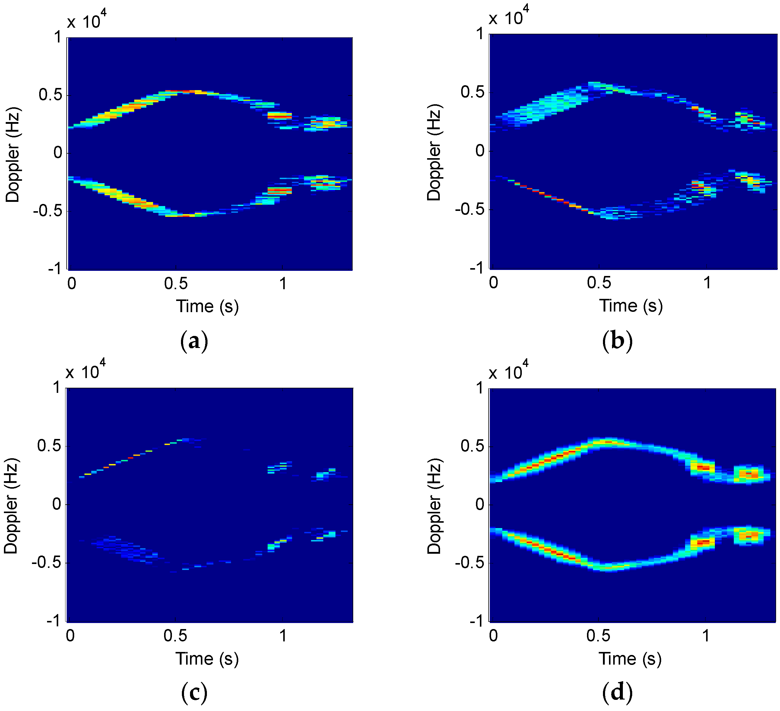
Figure 9 shows the analysis results of three time-frequency algorithms under different SNR backgrounds. A Gauss window is used as the window function. The window length is 4096 points and the order interval is 0.01.
As shown in
Figure 9b,c, STFRFT can obtain part signal of high time-frequency resolution when the order is 0.93 and 1.05. After comprehensive processing of all spectra, STFRFT (
Figure 9d) is found to have a better image than STFT (
Figure 9a).
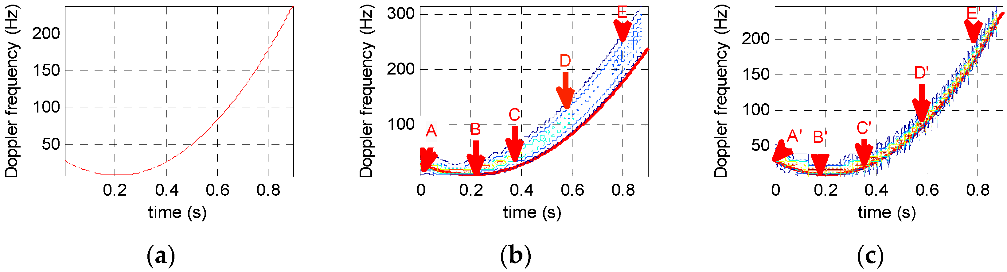
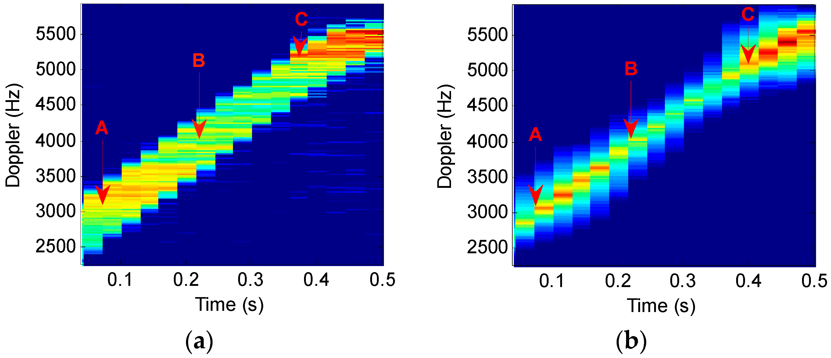
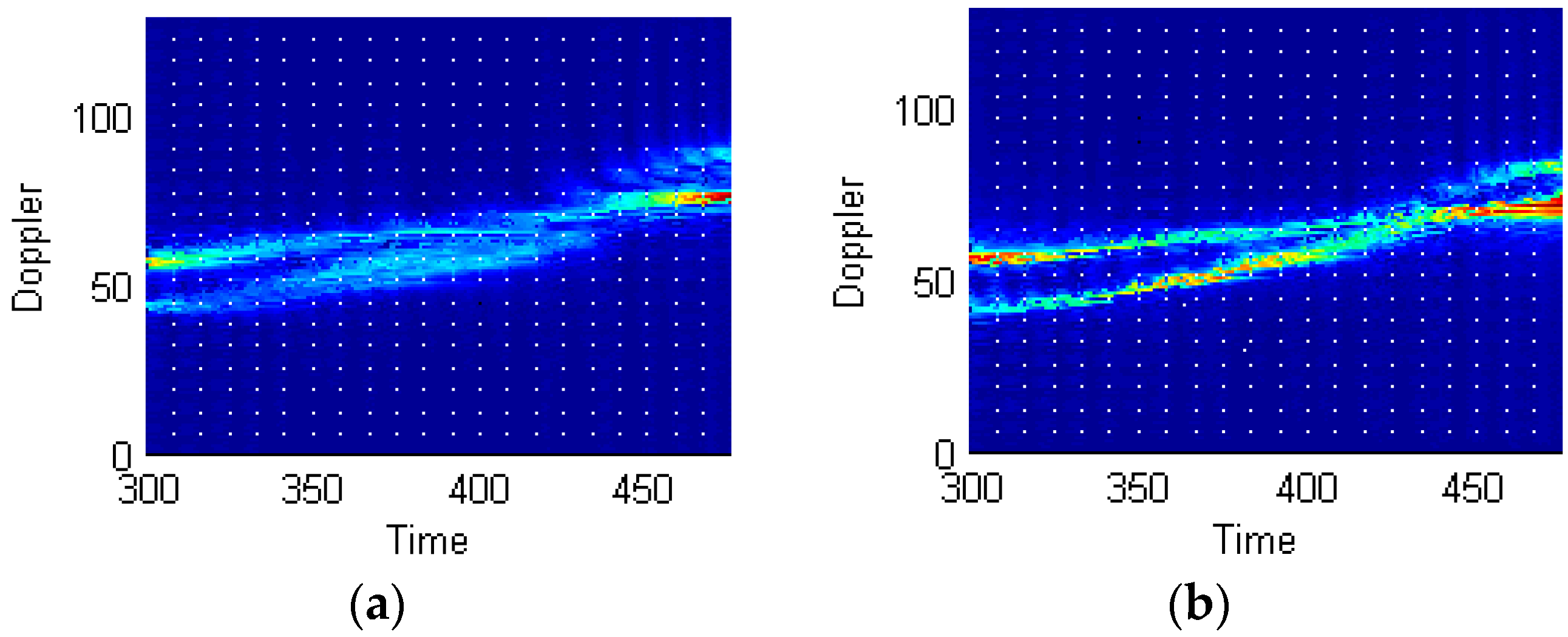
To underscore the meaningful improvement in time-frequency resolution performance,
Figure 10 compares, in an enlarged view, the portions of the STFT and STFRFT time-frequency images in
Figure 9a,d. Points A, B, and C in
Figure 10a,b are generated in the same time interval; the three points in
Figure 10a occupy 158, 189, and 235 frequency units respectively, while the three points in
Figure 10b occupy 124, 151, and 191 frequency units respectively. Drawing on [
13], we performed, by use of three-point method, Doppler frequency estimation of points A (0.1145, 3040), B (0.2577, 4468), C (0.4009, 4936) in
Figure 10a and points A (0.1145, 3028), B (0.2577, 4287), C (0.4009, 4926) in
Figure 10b, with the results being 0.52 Hz and 0.43 Hz respectively.
Table 4 compares the time-frequency resolutions achieved by STFT and STFRFT.
Table 4 suggests that STFRFT improves on STFT by about 25% on average in time-frequency resolution, good for improving time-frequency separation of multi-component signals and parameter estimation accuracy of Doppler frequency.
Relative to STFT, the proposed STFRFT is more effective in increasing the SNR of targets because for STFRFT the window contains signal of LFM form and for STFT sinusoidal form and, with the parameters being the same for both techniques, LFM signal is longer than a sinusoidal one, thus the energy is greater after accumulation, so is the SNR.
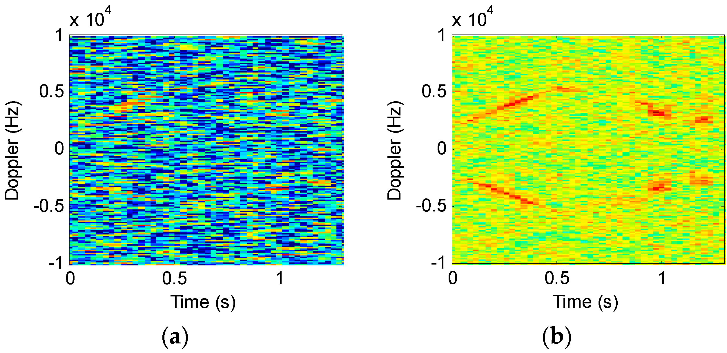
To demonstrate the effectiveness, we introduced −5 dB Gaussian noise while analyzing the original signal shown in
Figure 9;
Figure 11 compares the results of the two techniques, where STFT uses a window length of 2048 and STFRFT a length of 4096. It can be seen from
Figure 11 that—with a lower SNR—the detection effectiveness of STFT is degraded remarkably, as is evident in
Figure 11a, where the signal of the target is hardly discernible, whereas in the case of STFRFT the signal of the target remains discernible.
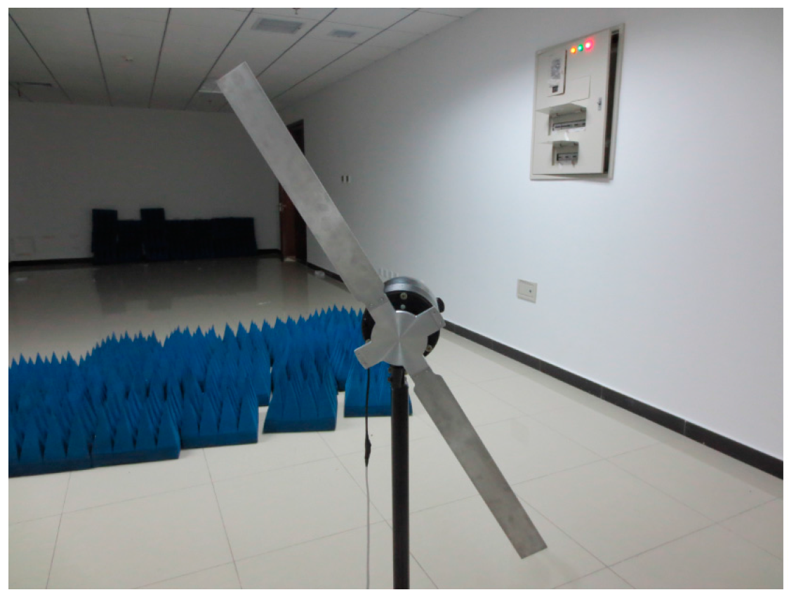
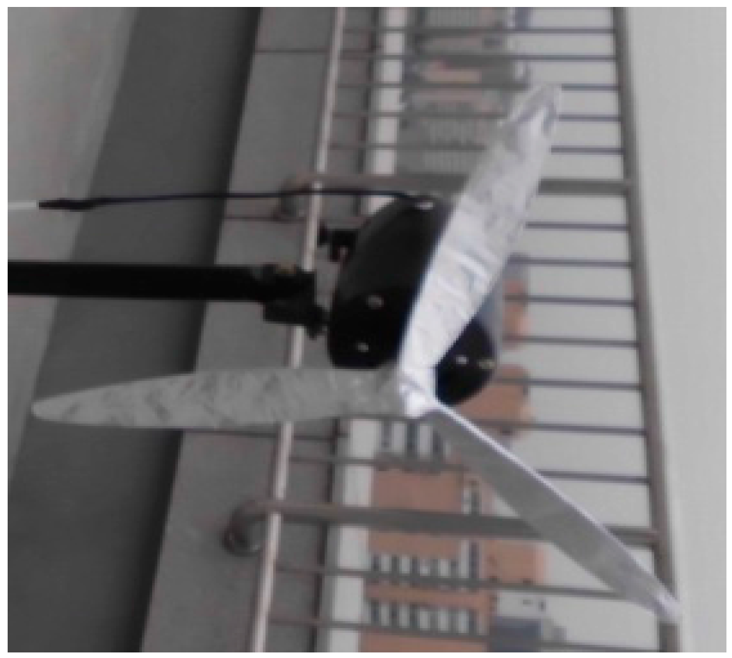
4.2. Signals from a Real Model Helicopter Target
In this experiment, a P-band radar system was used to acquire data on a model rotor helicopter for micro movement feature analysis. The model helicopter is Align 750e; its length, height, and width are 1343, 424 and 210 mm respectively. The main rotor is 700 mm long and the main rotor diameter is 1582 mm. The tail rotor wing is 281 mm in diameter and rotates at 26–42 r/s. The propeller is of co-axial single-blade type (two blades).
Table 5 lists the main parameters of the acquisition system used in this experiment.
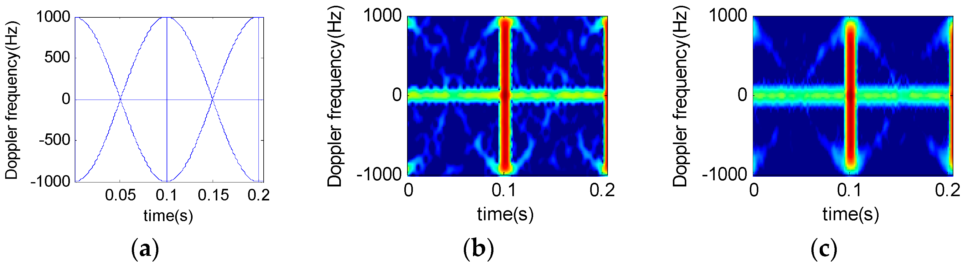
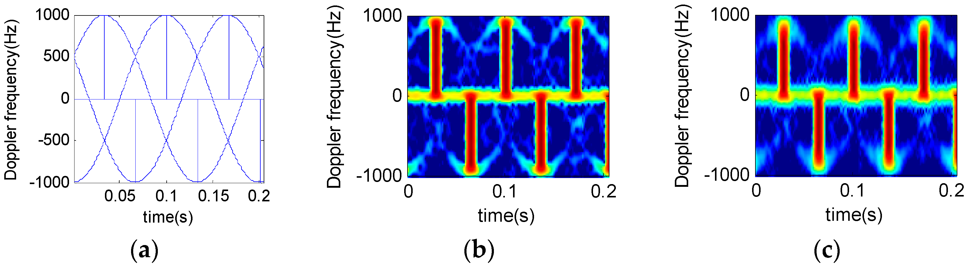
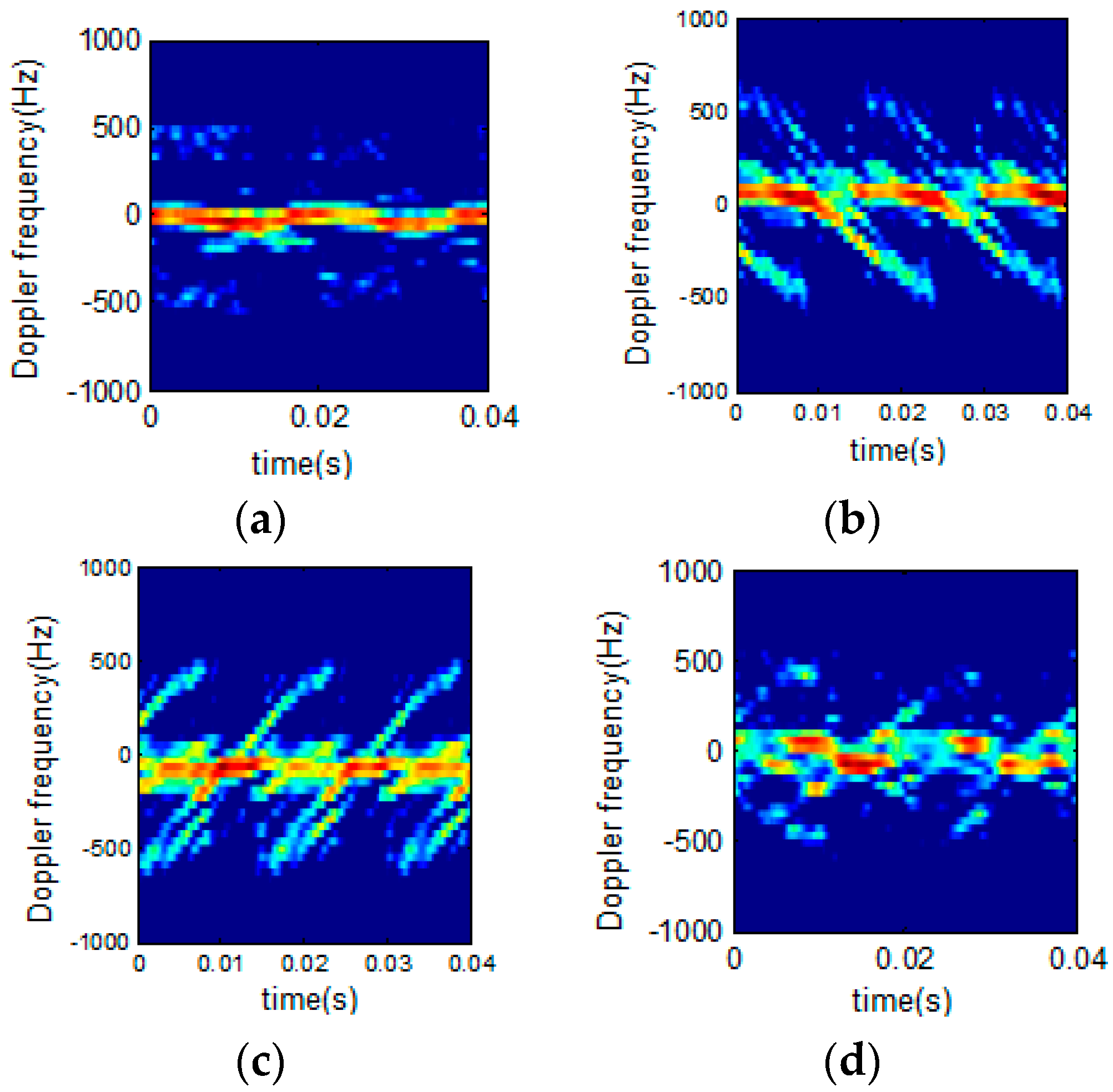
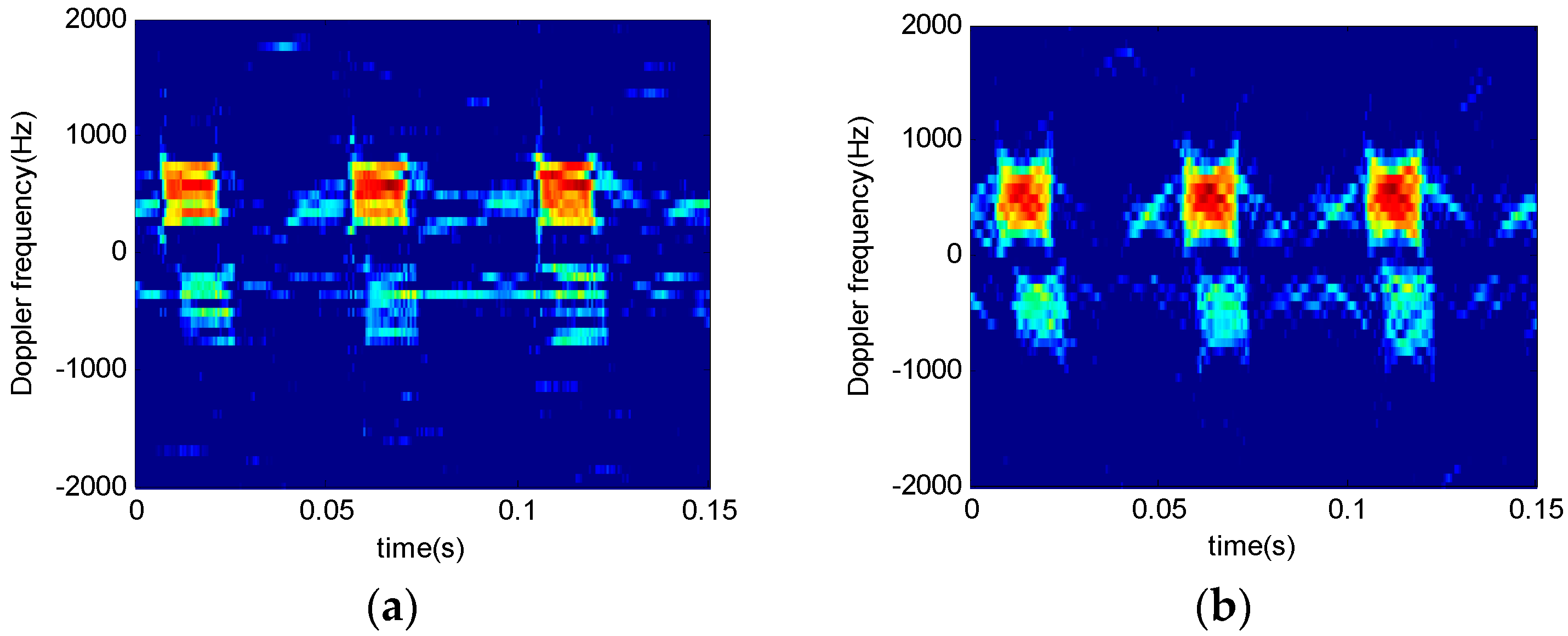
Figure 12 shows time-frequency analysis of
r echo signals from a two-blade rotor helicopter. The window length is 64 and the order interval is 0.1.
Figure 12a indicates that STFT algorithm works well only in the bottom and the top signal time-frequency analysis.
Figure 12b,c show the results when the order is not consistent. STFRFT performs better than STFT in both local signal detection and comprehensive frequency analysis. Finally, the rotation frequency of the propeller blade in
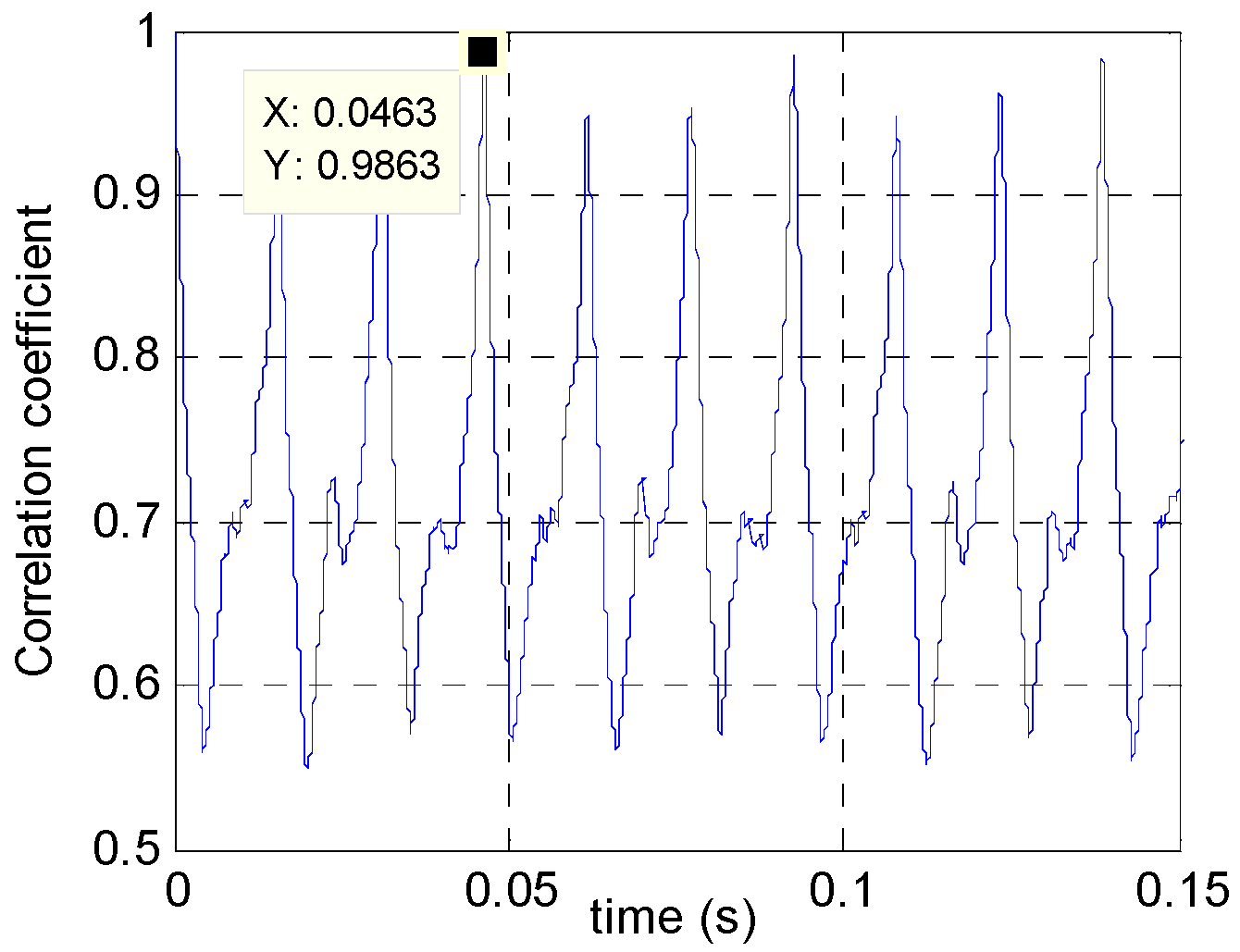
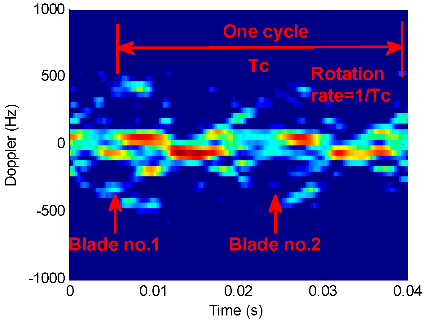
Figure 12d is 35 revolutions per second, which agrees with the theoretical value of the helicopter model. Please refer to the markings of the time-frequency curve parameters in
Figure 13 for the computation of the rotation rate of the propeller, where, Tc represents a rotational period of the propeller, the rotation frequency being the reciprocal of the period, i.e., 1/Tc.
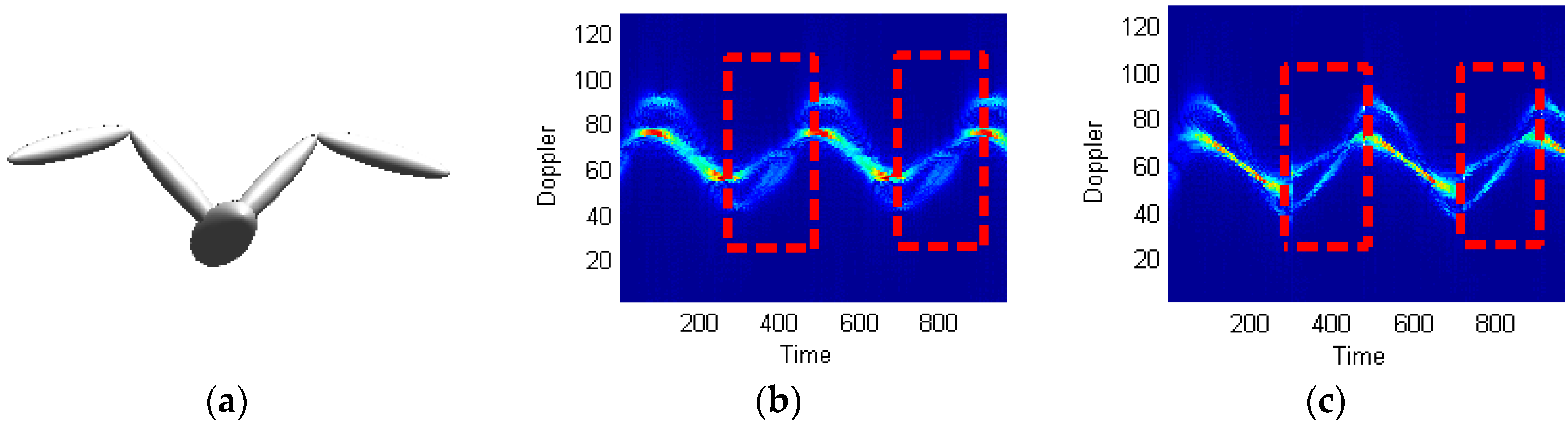
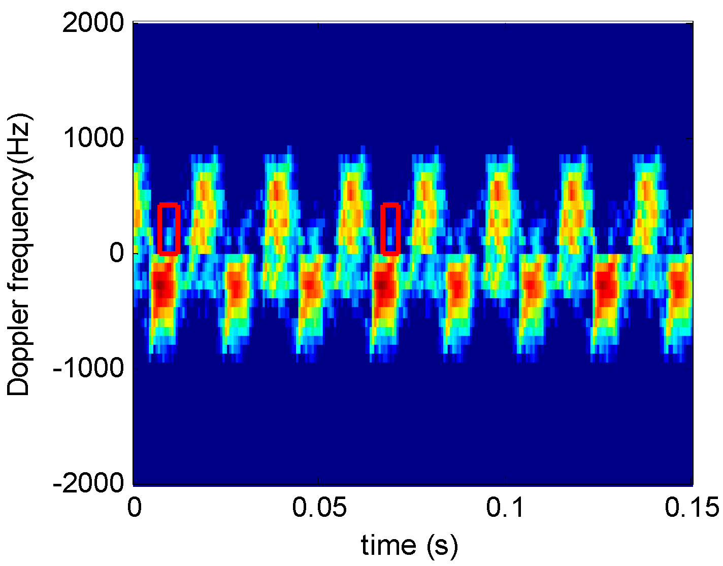
4.3. Signals from the Bird Target
Figure 14 shows the bird target model in [
35], the micro Doppler echo signal of which is analyzed using the proposed technique.
Supposing the radar wave length is 0.03 m, the time of accumulation is 10 s, the number of accumulated impulses is 8192, the bird wing length is 1 m (both the upper and lower arms being 0.5 m long), and the flapping frequency is 2 Hz.
Figure 14 shows the processing results using STFT and STFRFT and, for better revealing their differences,
Figure 15 provides enlarged views of the red box areas in
Figure 14. It is apparent that STFRFT performs appreciably better than STFT in time-frequency focusing.


